What do the Pilot fault codes mean? - B&G
What do the Pilot fault codes mean? - B&G
What do the Pilot fault codes mean? - B&G
- No tags were found...

Create successful ePaper yourself
Turn your PDF publications into a flip-book with our unique Google optimized e-Paper software.
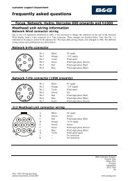
customer support departmentfrequently asked questionsH3000 <strong>Pilot</strong>“<strong>What</strong> <strong>do</strong> <strong>the</strong> <strong>Pilot</strong> <strong>fault</strong> <strong>codes</strong> <strong>mean</strong>?”Fault Cause Fault DescriptionFAULT 100FAULT 101FAULT 102FAULT 103FAULT 104FAULT 105FAULT 106FAULT 108FAULT 109FAULT 110FAULT 111FAULT 112FAULT 113FAULT 114FAULT 115NO PILOT<strong>Pilot</strong> not Commissioned<strong>Pilot</strong> Compass FailureRudder sensor out of RangeRudder DriveNo (or low) Boat SpeedSystem Compass FailureNo NMEA dataPoor Quality NMEA DataNo (or low) Wind SpeedNo Optimum Wind DataCurrent Trip (Drive or Clutch)Network Communication ErrorMemory Card ChangedMemory Card ErrorDrive Power FailureRudder not commissioned or memory corrupted.The signal from <strong>the</strong> <strong>Pilot</strong> compass is too big or too small.The signal from <strong>the</strong> rudder reference unit is outside <strong>the</strong> limitsset during commissioning.The <strong>Pilot</strong> attempted to move <strong>the</strong> rudder but did not sense anychange in rudder position.The boat is stationary or <strong>the</strong> speed sensor has stoppedtransmitting data.Compass data from Super Halcyon 3 via Instrument Systemnetwork has stopped.XTE data from position fixer via Instrument System networkhas stopped.The value of XTE data being received has suddenly changedby more than 0.3 nautical miles.There is no valid wind data being received via <strong>the</strong> InstrumentSystem network, or <strong>the</strong> wind speed is less than 1knot.There is no optimum wind angle data being received via <strong>the</strong>Instrument System network.The current limit circuit for <strong>the</strong> drive motor (25 amps) or <strong>the</strong>clutch (2 amps) has tripped.No regular messages being received by pilot control from pilotdisplay via instrument system network, i.e. ei<strong>the</strong>r <strong>the</strong> displayis not transmitting or <strong>the</strong> <strong>Pilot</strong> computer is not receiving.The memory card fitted is new or from ano<strong>the</strong>r <strong>Pilot</strong> and <strong>the</strong>rudder end-stopsare no longer valid.Ei<strong>the</strong>r <strong>the</strong> contents of <strong>the</strong> memory card fitted are notcompatible with <strong>the</strong><strong>Pilot</strong>, <strong>the</strong> memory card is <strong>fault</strong>y or no card is present.The <strong>Pilot</strong> processor PCB is unable to communicate with <strong>the</strong>drive PCB.No regular messages being received by pilot display frompilot control via instrument system network, i.e. ei<strong>the</strong>r <strong>the</strong>display is not receiving or <strong>the</strong> <strong>Pilot</strong> computer is nottransmitting.FAULT DIAGNOSISFault 100 – <strong>Pilot</strong> not CommissionedRemedial Action1. Has <strong>the</strong> <strong>Pilot</strong> ever been successfully commissioned?B&G Customer SupportPremier WayAbbey ParkROMSEYSO51 9DHUKRobert Langford-Wood Page 1FAQ - <strong>Pilot</strong> Fault Codeswww.bandg.com
customer support departmentfrequently asked questionsYes go to step (4)No go to step (2)2. Carry out <strong>the</strong> Dockside commissioning procedure (see <strong>Pilot</strong> manual page 56).Display <strong>the</strong> <strong>Pilot</strong> screen, move <strong>the</strong> helm, <strong>do</strong>es <strong>the</strong> rudder indicator function?Yes go to step (4)No go to step (3)3. The rudder indicator on <strong>the</strong> <strong>Pilot</strong> screen will not function if invalid rudder end and mid pointshave been entered. Check <strong>the</strong> rudder reference unit installation (see page 91) is such that <strong>the</strong>voltage difference between <strong>the</strong> port and starboard end stops is a minimum of 1.0 volt. Afterchecking repeat step (2).4. If <strong>the</strong> rudder has previously been successfully commissioned <strong>the</strong>n <strong>the</strong> <strong>fault</strong> is likely to be dueto memory corruption. This may be due to a recent change of software version or severeinterference (e.g. lightning). We recommend that you reset <strong>the</strong> <strong>Pilot</strong> computer (node 18) andattempt to re-commission <strong>the</strong> <strong>Pilot</strong>. If this fails contact your local specialist dealer.Fault 101 – <strong>Pilot</strong> Compass FailureRemedial Action1. Is an HGSC sensor in use?Yes go to step (3)No go to step (2)2. Ensure that <strong>the</strong> Heading Source (SETUP X COMMISSIONING X HEADING SOURCE to<strong>the</strong> correct value for <strong>the</strong> compass sensor in use.3. Check all wiring connections to <strong>the</strong> compass unit. There should be both a sensor cable AND a12V supply cable, see page 87 or 88Fault 102 - Rudder Sensor out of RangeRemedial Action1. Check installation of rudder reference unit for slack or loose fittings.Replace any worn parts and secure any loose items. If <strong>the</strong> position of any part has beenchanged it is necessary to follow <strong>the</strong> DocksideCommissioning procedure.2. Display <strong>the</strong> <strong>Pilot</strong> screen on a GPD, watch <strong>the</strong> rudder indicator carefully whilst turning <strong>the</strong>helm slowly from hard-over port to hard-over starboard. The indicated angle should changesmoothly as <strong>the</strong> wheel is turned.If <strong>the</strong> indicator <strong>do</strong>es not move at all follow <strong>the</strong> Dockside Commissioning procedureIf <strong>the</strong> indicator is erratic move to step (3)3. Check <strong>the</strong> voltage supply to <strong>the</strong> rudder reference is 4.5 to 5.0 volts.4. Check <strong>the</strong> signal from <strong>the</strong> rudder reference with a voltmeter at <strong>the</strong> <strong>Pilot</strong> computer.With someone moving <strong>the</strong> helm slowly port to starboard (as in step 2) <strong>the</strong> voltage shouldchange smoothly. If <strong>the</strong> signal is incorrect suspect a <strong>fault</strong>y rudder reference unit. Note: Thedifference between <strong>the</strong> signal voltages measured at <strong>the</strong> two end stops must be at least 1V dc.If <strong>the</strong> <strong>fault</strong> always occurs at <strong>the</strong> same rudder angle, suspect a <strong>fault</strong>y rudder reference unit.If <strong>the</strong> <strong>fault</strong> occurs at different rudder angles suspect a <strong>fault</strong> in <strong>the</strong> wiring connections to <strong>the</strong> <strong>Pilot</strong>computer or a <strong>fault</strong> with <strong>the</strong> <strong>Pilot</strong> computer electronics.B&G Customer SupportPremier WayAbbey ParkROMSEYSO51 9DHUKRobert Langford-Wood Page 2FAQ - <strong>Pilot</strong> Fault Codeswww.bandg.com
customer support departmentfrequently asked questionsFault 103 - Rudder DriveRemedial ActionIf <strong>the</strong> <strong>fault</strong> occurs all <strong>the</strong> time when <strong>the</strong> <strong>Pilot</strong> is engaged:1. Is <strong>the</strong> heavy-duty power supply circuit breaker for <strong>the</strong> <strong>Pilot</strong> drive switched on? If not <strong>the</strong> <strong>fault</strong>103 message may be triggered alongside a <strong>fault</strong> 115 message (see below).2. Move <strong>the</strong> helm. Does <strong>the</strong> rudder indicator work? if not check physical installation of <strong>the</strong>rudder reference unit as detailed above.3. Select Power mode. If drive system includes a clutch or solenoid valve (normal ram drivesand most mechanical rotary drives), engage <strong>the</strong> pilot and check <strong>the</strong> operation of <strong>the</strong> clutch orsolenoid valve. It should not be possible to move <strong>the</strong> helm with <strong>the</strong> <strong>Pilot</strong> engaged. If <strong>the</strong> helmcan be moved (i.e. <strong>the</strong> clutch fails to operate) disconnect <strong>the</strong> clutch from <strong>the</strong> <strong>Pilot</strong> electronicsand test its operation when connected directly to <strong>the</strong> drive power supply.4. With <strong>Pilot</strong> engaged in "Power Steer" mode use <strong>the</strong> 10º and 1º port and starboard keys to move<strong>the</strong> rudder. If <strong>the</strong> motor fails to run disconnect <strong>the</strong> motor from <strong>Pilot</strong> electronics and test <strong>the</strong>operation when connected directly to power supply.If <strong>the</strong> <strong>fault</strong> occurs intermittently or under heavy loads:1. Use power steer mode to move rudder while restricting movement by holding wheel. If <strong>the</strong><strong>fault</strong> occurs under <strong>the</strong>se conditions it could be due to:Excessive motor currentToo much slack or backlash in drive or fixing to tillerAir in hydraulic system2. Check <strong>the</strong> physical installation of <strong>the</strong> drive system for <strong>the</strong>se points.Fault 104 - No (or Low) Boat SpeedRemedial Action1. If <strong>the</strong> <strong>Pilot</strong> is taking boat speed from an instrument system check <strong>the</strong> speed shown on <strong>the</strong>instrument system display, if <strong>the</strong> instruments are showing an erroneous value <strong>the</strong>n investigate<strong>the</strong> cause on <strong>the</strong> instrument system (fouled sensor etc.)2. If <strong>the</strong> boat speed sensor is connected directly to <strong>Pilot</strong> check <strong>the</strong> wiring connections.3. Check <strong>the</strong> functionality of <strong>the</strong> speed sensor, change <strong>the</strong> Speed Source from Boat Speed toSOG or Manual Speed if <strong>the</strong> paddle wheel sensor is inoperative.Fault 105 - System Compass FailureRemedial Action1. Check <strong>the</strong> Heading Source is set correctly for <strong>the</strong> compass in use, see page 412. Check <strong>the</strong> heading data on <strong>the</strong> instrument system updates normally as <strong>the</strong> boat changescourse.3. Check <strong>the</strong> wiring connections for <strong>the</strong> compass sensor in use and <strong>the</strong> connection of <strong>the</strong> <strong>Pilot</strong>ACP to <strong>the</strong> Fastnet network.Fault 106 - No NMEA DataRemedial Action1. Check that <strong>the</strong> XTE data displayed on <strong>the</strong> instrument system is accurate and updatingregularly.B&G Customer SupportPremier WayAbbey ParkROMSEYSO51 9DHUKRobert Langford-Wood Page 3FAQ - <strong>Pilot</strong> Fault Codeswww.bandg.com
customer support departmentfrequently asked questions2. Check <strong>the</strong> operation of <strong>the</strong> position fixer, if <strong>the</strong> device no longer has a position fix it is likelythat <strong>the</strong> NMEA output has stopped. Refer to <strong>the</strong> troubleshooting guide in your position fixer<strong>do</strong>cumentation for fur<strong>the</strong>r information.Fault 108 - Poor Quality NMEA DataRemedial Action1. Check that <strong>the</strong> XTE data displayed on <strong>the</strong> instrument system is stable, accurate and updatingregularly.2. Check <strong>the</strong> operation of <strong>the</strong> position fixer, if <strong>the</strong> device no longer has a position fix it is likelythat <strong>the</strong> NMEA output has stopped. Refer to <strong>the</strong> troubleshooting guide in your position fixer<strong>do</strong>cumentation for fur<strong>the</strong>r information.Fault 109 - No (or Low) Wind SpeedRemedial Action1. Check <strong>the</strong> Measured Wind Speed (MWS) data displayed on <strong>the</strong> instrument system, if this isvery low, and <strong>the</strong>re is obviously a significant amount of wind, investigate <strong>the</strong> wind instrumentwiring connections.2. Check connections to instrument system.Fault 110 - No Optimum Wind DataRemedial Action1. Check <strong>the</strong> Optimum Wind Angle (OPT W/A) data displayed on <strong>the</strong> instrument system.2. Check connections to instrument system.Fault 111 - Current Trip: Drive or ClutchRemedial Action1. Check <strong>the</strong> installation and wiring for short circuits or loose connections.2. Check <strong>the</strong> current to <strong>the</strong> clutch, if this exceeds <strong>the</strong> maximum value <strong>the</strong> <strong>fault</strong> will occurimmediately.3. Check <strong>the</strong> current to <strong>the</strong> drive motor, if this exceeds <strong>the</strong> maximum value <strong>the</strong> <strong>fault</strong> will occurimmediately.Fault 112 - Network Communication ErrorRemedial Action1. Check <strong>the</strong> installation and operation of <strong>the</strong> <strong>Pilot</strong> display.2. If <strong>Pilot</strong> responds to commands from o<strong>the</strong>r displays <strong>the</strong>n <strong>the</strong> <strong>Pilot</strong> computer is operatingcorrectly. Check installation of Fastnet network cable.Fault 113 – Memory Card Changed: Reset End StopsRemedial ActionEi<strong>the</strong>r reset and re-commission <strong>the</strong> <strong>Pilot</strong> or, if you are certain <strong>the</strong> memory card has come from a <strong>Pilot</strong>of <strong>the</strong> same software version, carry out <strong>the</strong> Dockside Commissioning procedure to set <strong>the</strong> new rudderend stops.B&G Customer SupportPremier WayAbbey ParkROMSEYSO51 9DHUKRobert Langford-Wood Page 4FAQ - <strong>Pilot</strong> Fault Codeswww.bandg.com
customer support departmentfrequently asked questionsFault 114 – Memory Card ErrorRemedial Action1. Reset and re-commission <strong>the</strong> <strong>Pilot</strong>.2. If a reset is unsuccessful it may be necessary to replace <strong>the</strong> <strong>Pilot</strong> memory card, consult yourlocal dealer.Fault 115 – Drive Power Failure: Check SupplyRemedial ActionCheck to ensure <strong>the</strong> high current drive supply is present and is of <strong>the</strong> correct voltage. It is normal for<strong>the</strong> drive supply to be on a separate circuit breaker to <strong>the</strong> rest of <strong>the</strong> <strong>Pilot</strong> electronics, ensure thisbreaker (if present) is switched on.<strong>Pilot</strong> Display Shows "No <strong>Pilot</strong>"Remedial Action1. If o<strong>the</strong>r displays show <strong>Pilot</strong> data, check <strong>the</strong> Fastnet network installation of <strong>the</strong> affected <strong>Pilot</strong>display. If <strong>the</strong> installation is correct suspect a <strong>fault</strong> with <strong>the</strong> <strong>Pilot</strong> display unit.2. If no <strong>Pilot</strong> data is available on any display check <strong>the</strong> installation of <strong>the</strong> whole Fastnet network,if <strong>the</strong>re is an instrument system operating on <strong>the</strong> same network is that data available ondisplays? If <strong>the</strong> installation is correct, and <strong>the</strong> instrument system displays are functioning on<strong>the</strong> same network, suspect a <strong>fault</strong> with <strong>the</strong> <strong>Pilot</strong> computer.--ends--B&G Customer SupportPremier WayAbbey ParkROMSEYSO51 9DHUKRobert Langford-Wood Page 5FAQ - <strong>Pilot</strong> Fault Codeswww.bandg.com