H1000 NMEA Interface Installation Manual - B&G
H1000 NMEA Interface Installation Manual - B&G
H1000 NMEA Interface Installation Manual - B&G

Create successful ePaper yourself
Turn your PDF publications into a flip-book with our unique Google optimized e-Paper software.
universal interface boxinstallationIS-2509-02
CE Certification:This equipment generates, uses, and can radiate radio frequency energy and, if not installed and used inaccordance with the instructions, may cause harmful interference to radio communications. However, there is noguarantee that interference will not occur in a particular installation. If this equipment does cause harmfulinterference, the user is encouraged to try to correct the interference by relocating the equipment or connectingthe equipment to a different circuit. Consult an authorised dealer or other qualified technician for additional helpif these remedies do not correct the problem.This device meets requirements for CFR47 Part 15 of the FCC limits for Class B equipment.The h1000 meets the standards set out in European Standard EN 60945: 1997 IEC 945: 1996 for maritimenavigation and radiocommunication equipment and systems.
trademarkAll rights reserved. No part of this manual may be reproduced or transmitted in any form or by any meansincluding photocopying and recording, without the express written permission of B&G.Information in this document is subject to change without notice. B&G reserves the right to change or improve itsproducts and to make changes in the content without obligation to notify any person or organisation of suchchanges.technical specificationsDimensions:70mm x 135mm x 35mmPower Supply: 12V dc nominal (10V to 16V) via Fastnet 2Current Consumption:Operating Temperature range:Storage Temperature range:Humidity:50mA typical0°C to +55°C-25°C to +70°CUp to 95% RH
system connectionsFastnet 2CableFastnet 2CableHUB12V PowerCableFastnet 2CableconnectionsSystem components share data together via a common Fastnet 2databus and are supplied with bayonet connectors for ease ofinstallation. A selection of cable lengths are available with options forstraight and right angle connectors to suit most requirements.To prevent the occurrence of voltage drops on larger systems, thepower supply to the system should either be placed mid-way or at bothends of the Fastnet 2 databus. To connect power to the mid-point of thesystem, it is recommended that the 4-Way Hub be used. The 4-WayHub offers two advantages. The first advantage is that it offers aconvenient entry point for power onto the system. The secondadvantage is that it conveniently allows the system to be branched toreduce the overall length of the system. The correct selection ofFastnet 2 cable will negate the need for any plugs to be removed fromthe system and ensure years of faultless operation.<strong>NMEA</strong> interfaceThe National Marine Electronics Association (<strong>NMEA</strong>) is an organisation that has defined a number of standardspecifications for the interconnection of marine electronic instruments. These standards specify the electricalsignals and the format of the data that is transferred. This allows equipment such as the h1000 to communicatewith other manufacturers’ equipment.The Universal <strong>Interface</strong> is an <strong>NMEA</strong> interface specifically designed to allow the h1000 system to “talk” with othermanufacturers’ equipment. The most likely devices that will be connected to the Universal <strong>Interface</strong> are positionfixers such as GPS’s and Chart Plotters. The connection of navigational data to the h1000 Instrument allows thisdata to be displayed on the system and creates new calculated functions such as tide rate and direction.The Universal <strong>Interface</strong> has one <strong>NMEA</strong> Input Port (receive) and one <strong>NMEA</strong> Output Port (transmit) and isdesigned to comply with the latest <strong>NMEA</strong> 0183 standards. The Universal <strong>Interface</strong> also contains the connectionsfor an external alarm output. The individual <strong>NMEA</strong> sentences may be ‘Enabled’* or ‘Disabled’* as required fromthe ‘Remote unit setup’ options in the ‘System’ menu of any h1000 Digital display connected to the system.*Minimum software required: h1000-DSP – r2.05h1000-UNI – r2.04
supported <strong>NMEA</strong> sentences (v2.40)<strong>NMEA</strong> input (received) summary<strong>NMEA</strong> SentenceMessage DescriptionAPBHeading/Track Controller (Autopilot) Sentence “B”DBTDepth Below TransducerDPTTransducer Depth and OffsetGGA Global Positioning System Fix DataGLLGeographic Position, Latitude and LongitudeGSAGNSS DOP and Active SatellitesGSVGNSS Satellites in ViewHDGHeading Magnetic, Deviation and VariationMWDWind Direction and Speed (TWD °M / °T and TWS)MWV Wind Speed and Angle (AWS and AWA, flag set to R)RMBRecommended minimum navigation informationRMCRecommended minimum specific GNSS dataVHWWater Speed and Heading (°M / °T)VTGCourse Over Ground and Speed Over GroundZDATime and DateZTGUTC and Time to Destination Waypoint
supported <strong>NMEA</strong> sentences (v2.40), continuedB&G proprietary <strong>NMEA</strong> input (received) summary<strong>NMEA</strong> SentencePBGTTBSPBGTLAYPBGTVMGMessage DescriptionPolar speed (knots)Distance and Time to Lay-LineAngle for best VMG upwind (polar)Upwind heading for best VMG (polar)Downwind heading for best VMG (polar)<strong>NMEA</strong> output (transmitted) summary<strong>NMEA</strong> SentenceMessage DescriptionDPTTransducer Depth and OffsetGGAGlobal Positioning System Fix DataGLLGeographic Position, Latitude and LongitudeHDGHeading Magnetic, Deviation and VariationHDMHeading, MagneticHDTHeading, TrueMTW Water Temperature, °CMWDWind Direction and Speed (TWD °M / °T and TWS)MWV Wind Speed and Angle (AWS and AWA, flag set to R)RMBRecommended minimum navigation informationRMCRecommended minimum specific GNSS dataVHWWater Speed and Heading (°M / °T)VLWDistance Travelled through the WaterVTGCourse Over Ground and Speed Over Ground
selectable <strong>NMEA</strong>The Selectable <strong>NMEA</strong> feature allows control over which sentences are received and transmitted by the h1000Universal <strong>Interface</strong>. This gives flexibility when interfacing to other manufacturers’ products such as radars andchart-plotters. Selectable <strong>NMEA</strong> allows you to filter out unwanted <strong>NMEA</strong> messages and prevents duplicated dataon the system.3rd PartyGPSGPS <strong>NMEA</strong>Sentences3rd PartyPiloth1000-UNIh1000SystemGPS + Instrument<strong>NMEA</strong> Sentencesh1000-UNI3rd Party RadarPlotter/GPSInstrument<strong>NMEA</strong>SentencesConfiguring Selectable <strong>NMEA</strong>Identify the Universal <strong>Interface</strong> Box you wish to configure, this is identified by the first three digits of the serialnumber found on the printed label located inside the lid of the interface box. Select the chosen box from the listdisplayed, select either <strong>NMEA</strong> In or <strong>NMEA</strong> Out. The options available are detailed as follows:Selecting <strong>NMEA</strong> Input sentences – ‘Current Input’ - Press ENTER to select, press ENTER again and scrollthrough the listed sentences, press ENTER to view the options. Press ENTER and scroll to either On or Off,press ENTER to make your selection. Scroll to OK to return to the listed sentences. Repeat the operation untilyou have made all your selections.Selecting <strong>NMEA</strong> Output sentences – ‘Current Output’ - Follow the same procedure as detailed above.Renaming the interface box – ‘Name’ - Press ENTER to re-name the interface box (if required), use theUP/DOWN arrow keys to select the number or letter required (maximum 10 characters), once you havecompleted your name change scroll to, and highlight OK, press ENTER to return to the Remote units screen.
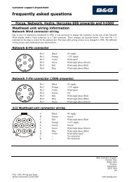
electrical connections2 35external connectionsTwo Fastnet² connectors are provided on the top ofthe unit. These connectors allow connection to therest of the system for the supply of power and data.14The table below shows pin functions.Front view ofmale connector pinsPinNumberSignal1 12V2 Busy3 Fastnet²-4 Fastnet²+5 0VGROMMETCABLE TIEPush the cable(s) through the grommet so that theouter insulation shows beyond the grommet andsecure using a cable tie as shown in the diagramopposite
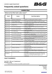
electrical connections<strong>NMEA</strong>ALARM<strong>NMEA</strong> TX+<strong>NMEA</strong> TX-<strong>NMEA</strong> SCN<strong>NMEA</strong> RX-<strong>NMEA</strong> RX+SCREENRED +No CONN.No CONN.BLUE -1 2 3 4 5 6 7 8 9 10UNIVERSALinternal connectionsWire the cables into the interface box as shown in thediagram opposite.methodTo open the connector, carefully push a small flatheaded terminal screwdriver into the slot directly abovethe relevant terminal number.Push the bare end of the wire into the terminalconnector and withdraw the screwdriver.Note: The maximum sink current for any alarmconnected to this interface box is 18mA.
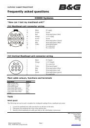
installation113.1mmDrill 4 off holes(2.9mmØ)forNo.6 x 3/4" selftapping screws53mmBGM01406248mmORIENTATIONBOX BASE OUTLINEWARNING: THIS DRAWING IS NOT TO SCALEUse the <strong>Installation</strong> instructions and the template provided with the unit packaging to install the <strong>Interface</strong> Box.