I-Series Universal Motor Mount Roller Screw Actuators ... - Exlar
I-Series Universal Motor Mount Roller Screw Actuators ... - Exlar
I-Series Universal Motor Mount Roller Screw Actuators ... - Exlar

Create successful ePaper yourself
Turn your PDF publications into a flip-book with our unique Google optimized e-Paper software.
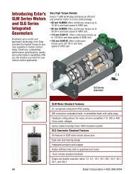
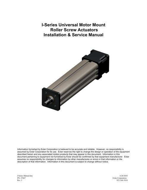
I-<strong>Series</strong> <strong>Universal</strong> <strong>Motor</strong> <strong>Mount</strong><strong>Roller</strong> <strong>Screw</strong> <strong>Actuators</strong>Installation & Service ManualInformation furnished by <strong>Exlar</strong> Corporation is believed to be accurate and reliable. However, no responsibility isassumed by <strong>Exlar</strong> Corporation for its use. <strong>Exlar</strong> reserves the right to change the design or operation of the equipmentdescribed herein and any associated motion products that may appear in this document. Information in thisdocument pertaining to equipment not furnished by <strong>Exlar</strong> should be confirmed by that equipment manufacturer. <strong>Exlar</strong>assumes no responsibility for changes to information by other manufactures or errors in that information or thedescription of that information. Information in this document is subject to change without notice.I <strong>Series</strong> Manual.doc 6/24/2010PN: 27667<strong>Exlar</strong> CorporationRev. I 952-368-3434
Table of Contents1.0 Introduction1.1 Warranty and Limitations of Liability1.2 Safety Considerations1.3 I <strong>Series</strong> <strong>Roller</strong> <strong>Screw</strong> Based Linear <strong>Actuators</strong> Overview1.4 Basic Actuator Construction1.5 Actuator Drive Train Configurations2.0 Installation2.1 <strong>Mount</strong>ing Configurations2.2 <strong>Mount</strong>ing Considerations2.3 Lubrication2.4 Anti-Rotate System3.0 Maintenance & Service3.1 Seals3.2 Thrust Bearings3.3 Drive Train3.4 <strong>Roller</strong> <strong>Screw</strong>3.5 End of Stroke Cushions3.6 Inspection and Lubrication Procedure3.7 Fastener Torque Values3.8 Pulley Set <strong>Screw</strong> Torque Values4.0 Optional Equipment4.1 <strong>Mount</strong>ing Options4.2 Standard <strong>Motor</strong> <strong>Mount</strong>ing Configurations4.3 Limit Switches4.4 Rod Ends4.5 <strong>Motor</strong>s4.6 Electronics5.0 Specifications5.1 Travel Life Calculations5.2 Load, Torque, and Linear Speed Calculations5.3 Load and Speed Ratings6.0 Troubleshooting6.1 Mechanical Problems6.2 Electrical ProblemsI <strong>Series</strong> Manual.doc 6/24/10PN: 27667 Page 2 <strong>Exlar</strong> CorporationRev. I 952-368-3434
1.0 Introduction1.1 Warranty and Limitations of LiabilityEXLAR warrants its product(s) to the original purchaser and in the case of original customer equipmentmanufacturers, to their original customer to be free from defects in material and workmanship and to bemade in accordance with the Buyer’s specifications which have been accepted in writing by EXLAR. Inno event, however, shall EXLAR be liable or have any responsibility under such warranty if theproduct(s) has been improperly stored, installed, used or maintained, or if Buyer has permitted anyunauthorized modifications, adjustments and/or repairs to such product(s).Seller’s obligation hereunder is limited solely to repairing or replacing (at its option), at the factory anyproduct(s), or parts thereof, which prove to Seller’s satisfaction to be defective as a result of defectivematerials or workmanship, and within the period of time, in accordance with the Seller’s stated productwarranty (see terms and conditions), provided, however, that written notice of claimed defects shall havebeen given to EXLAR within thirty (30) days from the date any such defect is first discovered. Theproduct(s) or part(s) claimed to be defective must be returned to EXLAR, transportation prepaid byBuyer, with written specification of the claimed defect.Components such as seals, wipers, bearings, bushings, splines, and roller screws are considered wearparts and must be inspected and serviced on a regular basis. Any damage caused by failure to properlylubricate EXLAR products and/or to replace wear parts at appropriate times, are not covered by thiswarranty.THE FOREGOING WARRANTY IS IN LIEU OF ALL OTHER WARRANTIES (EXCEPT AS TITLE),WHETHER EXPRESSED OR IMPLIED, INCLUDING WITHOUT LIMITATION, ANY WARRANTYOF MERCHANTABILITY, OR OF FITNESS FOR ANY PARTICULAR PURPOSE, OTHER THANAS EXPRESSLY SET FORTH AND TO THE EXTENT SPECIFIED HEREIN, AND IS IN LIEU OFALL OTHER OBLIGATIONS OR LIABILITIES ON THE PART OF EXLAR.SELLER’S MAXIMUM LIABILITY WITH RESPECT TO THESE TERMS AND CONDITIONS ANDANY RESULTING SALE, ARISING FROM ANY CAUSE WHATSOEVER, INCLUDING WITHOUTLIMITATION, BREACH OF CONTRACT OR NEGLIGENCE, SHALL NOT EXCEED THE PRICESPECIFIED HEREIN OF THE PRODUCT(S) GIVING RISE TO THE CLAIM, AND IN NO EVENTSHALL EXLAR BE LIABLE UNDER THIS WARRANTY OTHERWISE FOR SPECIAL,INCIDENTAL OR CONSEQUENTIAL DAMAGES, INCLUDING WITHOUT LIMITATION,DAMAGE OR LOSS RESULTING FROM INABILITY TO USE THE PRODUCT(S), INCREASEDOPERATING COST, LOSS OF PRODUCTION, LOSS OF SPECIAL INCIDENTAL ORCONSEQUENTIAL DAMAGES, WHETHER SIMILAR OR DISSIMILAR, OF ANY NATUREARISING OR RESULTING FROM THE PURCHASE, INSTALLATION, REMOVAL, REPAIR,OPERATION, USE OR BREAKDOWN OF THE PRODUCT(S), OR ANY OTHER CAUSEWHATSOEVER, INCLUDING NEGLIGENCE.The foregoing warranty shall also apply to products or parts which have been repaired or replacedpursuant to such warranty, and within the period of time, in accordance with Seller’s stated warranty.No person including any agent or representative of EXLAR, is authorized to make any representation ofwarranty on behalf of EXLAR concerning any products manufactured by EXLAR, except to referpurchasers to this warranty.I <strong>Series</strong> Manual.doc 6/24/10PN: 27667 Page 3 <strong>Exlar</strong> CorporationRev. I 952-368-3434
1.2 Safety ConsiderationsAs with any electro-mechanical device, safety should be considered during installation and operation ofyour I <strong>Series</strong> actuator. Throughout this manual you will see paragraphs marked with WARNING orCAUTION signs as shown below.CAUTIONWARNINGPay particular attention to these paragraphs. They are intended to provide you with helpful information toensure a safe and trouble free installation and operation.Care should be taken not to exceed the physical travel limits of I <strong>Series</strong> actuators.Doing so will cause the actuator to impact its end of travel bumpers. Repeatedend of travel crashes can physically damage the roller screw and the internalcomponents of the actuator.Care should be taken to avoid high speed impact with objects of high rigidity thatimmediately stop the travel of the actuator with no deceleration or energyabsorption. An example would be a high speed impact of two solid steel parts.The resulting impact will create a very short effective deceleration time. Kineticenergy contained in the rotating inertia of the actuator and motor can possiblygenerate extremely high impact forces that exceed the mechanical capacities ofthe actuator and cause physical damage to the actuator. For applicationsrequiring this type of impact, contact <strong>Exlar</strong> application engineering to insure thatthe actuator is properly sized or provisions are made to absorb the inducedenergy.I <strong>Series</strong> Manual.doc 6/24/10PN: 27667 Page 4 <strong>Exlar</strong> CorporationRev. I 952-368-3434
1.3 I <strong>Series</strong> Linear <strong>Actuators</strong> Overview<strong>Exlar</strong> I <strong>Series</strong> actuators are offered in three standard nominal frame sizes of 2, 3 and 4 inches.Continuous duty thrust load ratings for the I <strong>Series</strong> product range from 145 lbf to 3966 lbf. (644-17642 N)Intermittent load ratings for each actuator are twice the respective continuous duty load rating.<strong>Exlar</strong> I <strong>Series</strong> actuators utilize a planetary roller screw mechanism to converts rotary to linear motion.The planetary roller screw offers superior travel life, rigidity, and resistance to shock load than the ballscrews commonly found in electromechanical actuators. The planetary roller screw is mounted within asealed, extending tube package. The main rod extends or retracts as the input drive shaft is rotated. Thegeneral operating principle is illustrated below.CCW Shaft rotation looking at input shaft of base unit = Extending motionCW Shaft rotation looking at input shaft of base unit = Retracting motionThe I <strong>Series</strong> actuator designs offer contamination protection to IP54 or IP65 levels depending on thespecific series or options selected. All rotary to linear conversion components are mounted within an IP65or IP54 sealed housing. These levels of sealing protect the actuators internal components from particulatecontamination or from corrosive agents.1.4 Basic Actuator ConstructionThe IP65 I <strong>Series</strong> designs offer o-ring seals at each housing joint, and a rod wiper to seal out liquid andparticulate contaminates. Table of rod wiper manufacturer and PN can be found on page 27.The IP54 I <strong>Series</strong> designs offer protection from particulate contaminates, but are not sealed against liquidpenetration.The aluminum actuator case and housing parts are anodized. All steel mounting parts (flange mounts,side lug plates, trunnions, etc.) offer a black oxide finish. Corrosion resistant options offer thesemounting parts in stainless steel or with QPQ corrosion resistance heat treatment. Electroless Nickel andhard coat anodizing are available corrosion resistant options for the actuator housing and case parts.These finishes are intended to retard corrosion. The specific environment of the customer’s applicationshould be discussed with <strong>Exlar</strong> Corporation application engineers.I <strong>Series</strong> Manual.doc 6/24/10PN: 27667 Page 5 <strong>Exlar</strong> CorporationRev. I 952-368-3434
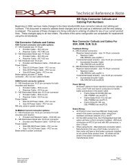
If the environment in which the I <strong>Series</strong> actuator will be commissioned involvescontact with corrosive substances, contact <strong>Exlar</strong> for application assistance.The standard I <strong>Series</strong> output rod is manufactured from 4100 <strong>Series</strong> steel and is heat treated with acorrosion resistance QPQ process that provides corrosion resistance and wear resistance.If the extending rod of the I <strong>Series</strong> actuator is subject to abrasions, scratches anddents, this will allow contaminants to be carried past the actuators or wiper andwill cause the wiper to wear prematurely allowing contamination to the internalcomponents of the actuator.1.5 Actuator ConfigurationsThe I <strong>Series</strong> base unit actuator includes a high performance planetary roller screw assembly, bearingsupport, anodized extruded aluminum housing, precision internal anti-rotate sliders, extending rod, and aninput shaft for attachment to your drive system. An I <strong>Series</strong> base unit is shown below.Input ShaftFigure 2: I <strong>Series</strong> Base Model ActuatorI <strong>Series</strong> Manual.doc 6/24/10PN: 27667 Page 6 <strong>Exlar</strong> CorporationRev. I 952-368-3434
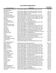
The I <strong>Series</strong> actuators are also available with provisions for mounting various motors. Standard motormountings include parallel with belt drive, inline direct drive, and inline with planetary gearing.The parallel motor mounting configuration utilizes a high performance belt drive system, which whileproviding quiet operation, requires no re-tensioning for the life of the actuator as long as the motor is notremoved or adjusted.Drive speed reduction ratios between 1:1 and 2:1 are available, with 1:1 and 2:1 being standard. Speedincreasing ratios are available also.Figure 3: I <strong>Series</strong> with Parallel <strong>Motor</strong> <strong>Mount</strong>I <strong>Series</strong> Manual.doc 6/24/10PN: 27667 Page 7 <strong>Exlar</strong> CorporationRev. I 952-368-3434
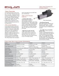
The inline motor mounting configuration uses a zero backlash coupling attaching the motors output shaftto the actuators drive shaft.Figure 4: I <strong>Series</strong> with Inline <strong>Motor</strong> <strong>Mount</strong>The inline planetary gearing option offers 5:1 or 10:1 planetary gear reduction. The planetary gearing isintegral to the input of the actuator and an inline coupling is included to attach the motor’s output shaft tothe input of the planetary gear stage.Figure 5: I <strong>Series</strong> with Inline Gearset <strong>Motor</strong> <strong>Mount</strong>I <strong>Series</strong> Manual.doc 6/24/10PN: 27667 Page 8 <strong>Exlar</strong> CorporationRev. I 952-368-3434
2.0 Installation2.1 <strong>Mount</strong>ing ConfigurationsThe I <strong>Series</strong> actuators offer a wide variety of mounting accessories. The standard mounting accessoriesare; side lug or foot mounts, side mounted flange attachments and side mounted trunnions. Each of thesemounting components utilize the T-Slot tracks on the sides of the case for attachment. Also available is afront flange mount that is integral to the actuator housing and does not attach via the T slots.2.2 <strong>Mount</strong>ing ConsiderationsCare should be taken to mount the I <strong>Series</strong> actuator such that its linear travel is well aligned with theallowable travel of its load. Misalignment imparts direct side load on the actuator’s extending rod. Sideloading of the actuators extending rod leads to accelerated seal wear, bearing wear and roller screw wear,and should be avoided.Excessive side load on the output rod of the actuator may reduce the travel andseal life of the actuator.T Slot mounting hardware should be attached perpendicular to the axis of linearmotion. All T-Nuts and associated flathead cap screws should be tightened to theappropriate torque level indicated in section 3.7 Fastener Torque Values.I <strong>Series</strong> Manual.doc 6/24/10PN: 27667 Page 9 <strong>Exlar</strong> CorporationRev. I 952-368-3434
<strong>Mount</strong>ing hardware installation:Step 1: Remove faceplate screwsStep 2: Remove faceplate and rod wiper. If O-Ringdoes not stay in place, remove that as well(IP65 units only)Step 3: You may preassemble the T-nuts, with mounting attachments and appropriate Flat Head Cap<strong>Screw</strong>s to be held loosely together as you guide the T-nuts into the slots. Alternatively, you can slip theT-Nuts into the slots, then assemble the mounting components and screws to the captive T-Nuts. Oncethe components are fully engaged in the T-nuts, it is advised that you lightly tighten one screw on eachmounting component to prevent it from sliding back and forth as you reassemble the actuator.I <strong>Series</strong> Manual.doc 6/24/10PN: 27667 Page 10 <strong>Exlar</strong> CorporationRev. I 952-368-3434
I <strong>Series</strong> <strong>Mount</strong>ing Hardware Torque SpecificationsActuator Component in-lbs ft-lb N-mIM/X20 <strong>Mount</strong>ing Component T Nut/bolt, Black Oxide 252 21 28.5IM/X20<strong>Mount</strong>ing Component T Nut/bolt, StainlessSteel 169 14 19.1IM/X30 <strong>Mount</strong>ing Component T Nut/bolt, Black Oxide 252 21 28.5IM/X30<strong>Mount</strong>ing Component T Nut/bolt, StainlessSteel 169 14 19.1IM/X40 <strong>Mount</strong>ing Component T Nut/bolt, Black Oxide 252 21 28.5IM/X40<strong>Mount</strong>ing Component T Nut/bolt, StainlessSteel 169 14 19.1All values are assuming dry (not oily or plated components)Step 4: Rotate the drive shaft to extend the main rod about 2” from the fully retracted position. If the O-Ring has been removed, place O-Ring grease in the groove and fit the O-Ring back into the groove. Slidethe wiper onto the main rod, leaving enough space for your fingers between the wiper and the front of thecase. The flange on the wiper points towards the rod end as shown. Put the face Plate over the rod (withthe counter bore for the wiper facing the wiper) and with your fingers press the wiper into the faceplatecounter bore, while keeping it on the main rod cylinder. Then press the faceplate down onto the O-Ringand rotate it so the holes line up.I <strong>Series</strong> Manual.doc 6/24/10PN: 27667 Page 11 <strong>Exlar</strong> CorporationRev. I 952-368-3434
Step 5: Torque faceplate screws to recommended value (see Section 3.4) Position mounting hardware tothe same distance from the face plate and torque Flathead Cap <strong>Screw</strong>s to their recommended value.2.3 Lubrication<strong>Exlar</strong>’s I <strong>Series</strong> actuators are shipped from the factory fully lubricated with a high temperature grease.Periodic inspection and renewal of the bearing and roller screw grease is recommended according to theperiods shown in the table below. Follow the procedure in section 3.6 for renewing grease.RMS Rotational Speed (rpm) Recommended Grease Renewal Period (hours)250 10,000500 10,0001000 80001500 70002000 58002500 50003000 4000For duty cycles of varying speeds use RMS rotational speed to determine grease renewal period. Todetermine this value follow the equation below:V rms = [(V 1 2 t 1 + V 2 2 t 2 +V 3 2 t 3 +…)/(t 1 +t 2 +t 3 +…)] 1/2Where:V rms = RMS Rotational speed (rpm)V 1,2,3… = Rotational speed of roller screw shaft for corresponding t 1,2,3… time (rpm)t 1,2,3… = Time at corresponding V 1,2,3… rotational speed (minutes)Over greasing or cold grease may cause elevated motor torque.<strong>Exlar</strong> recommends using Mobilith SHC 220, a high performance, extreme-pressure grease. The uniquephysical properties of the synthetic base oil provides outstanding protection against wear, rust, corrosionand high or low-temperature degradation. Mobilith SHC allows for very low starting and running torquevalues. Its operating range is -40 degrees C to 177 degrees C (-40 degrees F to 350 degrees F).For lubrication of seals see section 3.1.For inspection and lubrication procedure see section 3.6.2.4 Anti-Rotate Mechanism<strong>Exlar</strong>’s I <strong>Series</strong> actuators have an internal anti-rotate mechanism. Internal anti-rotation sliders travel inchannels integral to the actuator case. The anti-rotate mechanism limits angular motion to 0.35 degreesrotation and is designed to withstand the maximum rated input torque for each respective actuator size.Care should be taken when applying torque to the actuators main rod during rod end or load attachment tonot damage the anti-rotate mechanism. The I <strong>Series</strong> standard main rod designs offer wrench flats thatI <strong>Series</strong> Manual.doc 6/24/10PN: 27667 Page 12 <strong>Exlar</strong> CorporationRev. I 952-368-3434
should be used to resist the torque applied when attaching rod end accessories or load attachments. Theanti-rotate mechanism should not be used to resist this assembly torque. The anti-rotate mechanism isalso the housing for the magnet sensed by the optional limit switches.(See Part Numbersin table below)Figure 6: Anti-Rotate MechanismAnti-Rotation PartsI 2042901 Anti-Rotate Bearing 2 per actuator25935 Magnet, Ø1/8X ¼” , Neo-35 2 per actuatorI 3042902 Anti-Rotate Bearing 2 per actuator25935 Magnet, Ø1/8X ¼” , Neo-35 2 per actuatorI 4027523 Anti-Rotate Bearing 2 per actuator25935 Magnet, Ø1/8X ¼” , Neo-35 2 per actuatorTo avoid damage to the anti-rotate mechanism, care should be taken duringassembly to avoid applying more torque to the main rod than shown below.I 20----5 FT*LBF (6.8Nm)I 30----10 FT*LBF (13.6 Nm)I 40----25 FT*LBF (33.9 Nm)I <strong>Series</strong> Manual.doc 6/24/10PN: 27667 Page 13 <strong>Exlar</strong> CorporationRev. I 952-368-3434
3.0 Maintenance & Service3.1 SealsI <strong>Series</strong> actuators provided with IP65 sealing have Buna-n o-rings at the joints of the actuator housingcomponents. The extending rod is sealed with a wiper seal. The input shaft of an IP65 unit is sealed usinga spring loaded nitrile shaft seal that is contained within the back end plate of the actuator. These sealsare lubricated on initial assembly with a teflon seal lubricant. The front wiper should have a small amountof mineral oil applied to it periodically depending on amount of actuator use or storage to keep the wiperoperating smoothly and to prolong life. The o-rings are treated with a o-ring lubricant designed toslightly swell the o-ring to assure proper sealing.IP65 versions of the inline motor mount and inline gear set actuators have additional o-rings (or gasketson I 40) between the actuator base unit and the motor mounting plate or gear set housing section. Inparallel mounted units the pulley housing is not sealed but may be equipped with drain holes. Contact<strong>Exlar</strong> application engineers for details about custom sealing options.Figure 7-1: IP65 Base Unit Sealing DetailsFigure 7-2: IP65 Integrated <strong>Motor</strong> <strong>Mount</strong> Unit Sealing DetailsI <strong>Series</strong> Manual.doc 6/24/10PN: 27667 Page 14 <strong>Exlar</strong> CorporationRev. I 952-368-3434
Figure 7-3: IP65 Gear set/Integrated <strong>Motor</strong> <strong>Mount</strong> Unit Sealing Details3.2 Thrust BearingsIM <strong>Series</strong> actuators offer two deep groove ball bearings. IX series actuators provide two angular contactbearings mounted in duplex arrangement. These bearings support the drive shaft within the I <strong>Series</strong>actuator. The inner races of the angular contact bearings are pre-loaded using a bearing jam nut and lockwasher to ensure that the pre-loaded condition is not lost. The outer races are pre-loaded by the end platescrews as shown in figure 8.Figure 8: <strong>Roller</strong> <strong>Screw</strong> Support Bearing Detail3.3 Drive TrainThe parallel motor mount option for the I <strong>Series</strong> actuators provides a fiberglass reinforced belt and pulleydrive train to transmit the motors rotation and torque to the actuators roller screw mechanism. The drivetrain does not require lubrication. The belt and pulley transmission is housed in a protective housing tohelp prevent contamination by dirt and debris. The belt housing and cover should be kept in place at alltimes during operation and should only be removed for motor mounting and drive train inspection. Thebelt and pulley system should be inspected periodically for wear and proper tensioning.I <strong>Series</strong> Manual.doc 6/24/10PN: 27667 Page 15 <strong>Exlar</strong> CorporationRev. I 952-368-3434
Removing the protective housing from the belt and pulley drive train duringoperation of the actuator may cause damage to the actuator components orsevere injury. Power should be removed and locked out from the actuators motorat any time the the protective drive train cover is removed. Failure to do so canresult in damage to the actuator or cause serious injury.Improper belt tension can cause premature belt wear and failure, belt noise and slippage. The followingpicture is an example of a typical belt and pulley drive train in an I <strong>Series</strong> actuator. Actual drive trainswill vary in configuration depending on exact actuator and motor configuration. Contact <strong>Exlar</strong>application engineers with any questions regarding the installation or maintenance of the belt and pulleydrive train on your I <strong>Series</strong> Actuator.Figure 9: Parallel <strong>Motor</strong> <strong>Mount</strong> Drive Train AssemblyI <strong>Series</strong> Manual.doc 6/24/10PN: 27667 Page 16 <strong>Exlar</strong> CorporationRev. I 952-368-3434
Proper Belt TensionParallel <strong>Motor</strong> <strong>Mount</strong>ingThe motor plate slots allow dropping of the motor so the belt can be placed, followed by raising the motorto tighten the belt.IM/X20 and IM/X30 Belt TensioningThe standard Size 20 and 30 I <strong>Series</strong> belts are GT2 belts, 5mm pitch, 9mm width.The proper tension for these belts is 1.5 lbs deflection tension for 1/64” deflection per inch of span.The standard center to center distances of the pulleys are:1:1 Ratio: t = 3.642 inches (92.51 mm)1:2 or 2:1 Ratio: t = 3.519 inches (89.38 mm)Non-standard configurations may have varying center to center distances.For standard units, the deflection should be:1:1 Ratio: 1.5 lbs @ 0.057” deflection (0.68 kg @ 1.45 mm)1:2 or 2:1 ratio: 1.5 lbs @ 0.055” deflection (0.68 kg @ 1.40 mm)IM/X40 Belt TensioningThe I 40 uses a 5mm pitch by 9mm wide belt for lower torque applications and an 8 mm pitch by 22 mmwide belt for higher torque applications.I <strong>Series</strong> Manual.doc 6/24/10PN: 27667 Page 17 <strong>Exlar</strong> CorporationRev. I 952-368-3434
For the 9 mm wide belt, the proper tension is 1.5 pounds force to obtain 1/8 inches of deflection at thecenter of the belt between the two pulleys.For the 22 mm wide belt, the proper tension is at 4.5 pounds force to get 1/8 inch of deflection at thecenter of the belt between the two pulleys.These tensioning values apply to all pulley ratios used I the I 40.To identify which belt is used, a 9 mm wide belt = .35 inches wide, or approximately 3/8 of an inch, and a22 mm wide belt = .866 inches or approximately 7/8 of an inch wide.Inline <strong>Motor</strong> <strong>Mount</strong>ing (motor adapter or gear set motor adapter)1.) Remove the clamp access plug by levering under the cap with a flat bladed screwdriver.2.) Loosen the collar clamp screw so the motor shaft can slide into the shaft adapter/coupler shaft, butmaintain enough pressure so the clamp screw stays aligned with the access hole.3.) Position the splits in the clamp collar, motor coupler, and shaft adapter so they are not lined up witheach other.4.) Place the actuator vertically with the motor mount facing up. Assembling in a vertical orientation willprevent unwanted side load being applied by the motor’s weight.5.) IP65 UNITS: Place appropriate o-ring around the motor pilot.6.) Insert the shaft of the motor into the shaft adapter/ motor coupler. Slide the motor down so the motorflange is flush with the motor adapter plate.7.) Rotate the motor so the mounting holes line up with the holes in the actuator’s motor adapter plate.8.) Lightly tighten the motor mounting bolts, taking care to maintain alignment without imparting anyside loading on the motor shaft.9.) Tighten motor bolts to the designated torque value. (See table in Section 3.7)10.) Tighten the collar clamp screw to 100 in-lbs using a hex key wrench.I 20 : Depending on size of clamp, either 1/8” or ¼” hex key wrenchI 30: ¼” hex key wrenchI 40: 3/16 inch hex key wrench11.) Replace the clamp access plug.Do not tighten the collar clamp before tightening the motor mounting bolts. Thiswill introduce compression loads into the motor and actuator bearings that mayreduce the life of each.I <strong>Series</strong> Manual.doc 6/24/10PN: 27667 Page 18 <strong>Exlar</strong> CorporationRev. I 952-368-3434
3.4 <strong>Roller</strong> <strong>Screw</strong>The planetary roller screw used within the I <strong>Series</strong> actuators is a precision mechanism. The standardactuator will be supplied lubricated and sealed from the factory. Lubrication of the roller screw should bemaintained in accordance with section 2.3. Shock load and radial load should be avoided to providemaximum life from the actuator.Extending or retracting the roller screw into the ends of travel may cause damageto the actuator or the other components of the application.For roller screw life calculations and specifications see section 5.0.3.5 End Of Stroke CushionsEvery standard I <strong>Series</strong> actuator is equipped with nitrile rubber impact bumpers, which aredesigned to protect the actuator from accidental over extension or retraction.End of stroke cushions are provided for fail safe only and should not be used asan application limit of stroke.I-<strong>Series</strong> <strong>Actuators</strong> are designed with an additional 0.4” (10.16 mm) of length over nominal stroke. This isto allow users to utilize the full nominal stroke without causing damage by end crashing. See figures 10-1to 10-3 for information on stroke limits and how to position limit switches.Figure 10-1: Actuator Shown in fully retracted “crash” position, with contact on forwardimpact bumperI <strong>Series</strong> Manual.doc 6/24/10PN: 27667 Page 19 <strong>Exlar</strong> CorporationRev. I 952-368-3434
AAFigure 10-2: Actuator Shown in maximum recommended retract position, with 0.2” (5.08mm) of clearance on forward impact bumper.BFigure 10-3: Actuator Shown in maximum recommended extension position, with 0.2”(5.08 mm) of clearance on aft impact bumper.Recommended Limit Switch Positions for Magnet Sensing in I <strong>Series</strong>Dim ADim BI 20 2.47 in (62.7 mm) 1.29 in (32.8 mm)I 30 3.40 in (86.4 mm) 2.15 in (54.6 mm)I 40 5.20 in (132.1 mm) 2.54 in (64.5 mm)Care should be taken not to exceed the physical travel limits of I <strong>Series</strong> actuators.Doing so will cause the actuator to end-crash internally. End crashes canphysically damage the roller screw and the internal components of the actuator.I <strong>Series</strong> Manual.doc 6/24/10PN: 27667 Page 20 <strong>Exlar</strong> CorporationRev. I 952-368-3434
3.6 Inspection and Lubrication ProcedureThe following disassembly and reassembly procedures are general guidelines. Individual designs maydiffer from these procedures and any questions should be verified with <strong>Exlar</strong> before reassembling andreinstalling the actuator into your machine or application. For both procedures refer to the drawingsincluded in the disassembly procedure for reference only. For torque values see chart in Section 3.7.Parallel <strong>Mount</strong> Disassembly:Figure 11: Parallel <strong>Motor</strong> <strong>Mount</strong> Drive Train Assembly1. Remove power and dismount the actuator from the application2. Remove pulley cover and cover plate by removing cover screws and pulling cover and plate awayfrom the motor plate.3. Loosen motor mounting screws and slide motor down to relieve tension on belt. Once the belt canclear the pulley flange, remove the belt. Mark the position of the pulleys on the shafts—this will aidpositioning in reassembly and ensure that the pulleys are parallel when reassembled.4a. Loosen the set screws on motor and actuator shaft pulleys and slide the pulleys off the shafts. Takecare not to damage the flanges on the flanged pulley, as these are made of aluminum and can be bent ifsubjected to prying forces.4b. Loosen the bolts on the pulley taper couplings and slide pulleys off the shafts.I <strong>Series</strong> Manual.doc 6/24/10PN: 27667 Page 21 <strong>Exlar</strong> CorporationRev. I 952-368-3434
5. Support the motor, and remove the motor screws, washers, and nuts from the motor plate. Remove themotor.6. Loosen and remove the four motor mounting screws. (I20 and I30 use ¼-20 and I40 uses 5/16-18).Remove the motor plate. If the unit is IP65 sealed, there will be O rings and shaft seals to be removedalso. Remove the aluminum bearing spacer ring if possible, but if this is difficult it can be popped outwhen the actuator is pressed out of the case.7. Proceed to the section on Actuator Disassembly.Inline <strong>Motor</strong> <strong>Mount</strong> Disassembly:Figure 12: Inline <strong>Motor</strong> <strong>Mount</strong> Disassembly1. Remove the actuator assembly from the application or machine by removing power from the motor,disconnecting main rod coupling and actuator mounting bolts or fasteners.2. Pry access cap from access hole on motor plate.3. Using a (1/4” for I30 or larger motor I20); (1/8” for smaller motor I20) hex key wrench, reach into theaccess hole and turn the collar clamp until the cap screw socket is accessible. Then loosen the collarclamp. (Note: if the motor is equipped with an electronic brake, you may have to disable the brake toturn the motor shaft.)4. Support the motor so it will not fall, and remove the motor screws, washers, and nuts from the motorplate. Remove the motor. If the unit is IP65 sealed, remove the motor pilot O-Ring.I <strong>Series</strong> Manual.doc 6/24/10PN: 27667 Page 22 <strong>Exlar</strong> CorporationRev. I 952-368-3434
5. Remove the motor adapter mounting screws. Remove the inline motor adapter. Some models willhave a two-part motor adapter/end plate, which will require removal of two components and associatedscrews sequentially. The collar clamp can be slipped off as the motor adapter is removed, by pulling onthe adapter as you twist it back and forth. If the unit is IP65 sealed, the shaft seal and ORings will need tobe removed.6. Some motors will require a slotted shaft adapter inside the motor coupler. If present, remove this toprevent it from falling out and getting lost.7. Proceed to the section on Actuator Disassembly.Inline gear set/motor mount disassembly:Figure 13: Inline gear set/<strong>Motor</strong> <strong>Mount</strong> Disassembly1. Remove the actuator assembly from the application or machine by removing power from the motor,disconnecting main rod coupling and actuator mounting bolts or fasteners.2. Pry access cap from access hole on motor plate.3. Using a (1/4” for I30 or larger motor I20); (1/8” for smaller motor I20) hex key wrench, reach into theaccess hole and turn the collar clamp until the cap screw socket is accessible. Then loosen the collarclamp. (Note: if the motor is equipped with an electronic brake, you may have to disable the brake to turnthe motor shaft.)4. Support the motor so it will not fall, and remove the motor screws, washers, and nuts from the motorplate. Remove the motor. If the unit is IP65 sealed, remove the motor pilot O-Ring.I <strong>Series</strong> Manual.doc 6/24/10PN: 27667 Page 23 <strong>Exlar</strong> CorporationRev. I 952-368-3434
5. Remove the motor adapter mounting screws. Remove the inline motor adapter. If the unit is IP65sealed, remove the o-ring.6. Remove the gear housing and collar clamp. The collar clamp can be slipped off as the gear housing isremoved, by pulling on the housing as you twist it back and forth. If the unit is IP65 sealed, the shaft sealand o-ring will need to be removed.7. Some motors will require a slotted shaft adapter inside the motor coupler. Remove the slotted shaftadapter if present.8. Remove the planetary gear set’s sun gear assembly by pulling it away from the actuator. A slight sideto side motion may assist in removing it. If the unit is IP65 sealed, remove the case o-ring.9. The ring gear with its centering o-rings and the Spacer ring may have to be pushed out of the case withthe main actuator mechanism. Take care to retain these components during disassembly.10. Proceed to the section on Actuator Disassembly.If the actuator with which you are working has a preloaded follower, do not remove thenut or screw. Contact <strong>Exlar</strong> Corporation and arrange to have maintenance and/orrelubrication performed on the actuator by an authorized <strong>Exlar</strong> repair facility.I <strong>Series</strong> Manual.doc 6/24/10PN: 27667 Page 24 <strong>Exlar</strong> CorporationRev. I 952-368-3434
Actuator DisassemblyFigure 14: Actuator Disassembly1. Extend the main rod a few inches by turning the exposed drive shaft. Place the actuator rod side up inan arbor press, with the aft end of the case supported but with nothing interfering with the bearings asthey are pushed out. Push down on the rod end until the bearings are pushed out of the case, taking careto prevent the inner mechanism from dropping and being damaged as the bearings clear the bore.2. Remove the four (1/4-20 in I30; 10-32 in I20) screws and the front face plate. Remove the rod wiperfrom the face plate. Remove the aluminum front bearing housing (containing the linear bearings) fromthe case.3. Pull the anti-rotate assemblies from the main rod.Do not attempt to remove or reinsert the drive shaft/roller screw without firstremoving the anti-rotate assembly.4. Rotate the drive shaft counter-clockwise to remove it from the threaded cylinder.5. Using a round brush and degreasing agent, remove all old grease from the roller screw, bearings andanti-rotate mechanism.I <strong>Series</strong> Manual.doc 6/24/10PN: 27667 Page 25 <strong>Exlar</strong> CorporationRev. I 952-368-3434
Regreasing:1. Apply a line of grease between each of the rollers on the roller screw. Apply two thin lines of greaseto the inside of the threaded cylinder, at 180 o to each other.Take care to prevent foreign objects from entering the actuator or contaminatingthe grease.Apply new grease with a brush or grease gun. Excessive grease is unnecessary and will increase thetorque required to rotate the actuators roller screw. Insert the roller screw into the threaded cylinder androtate the drive shaft clockwise until the roller screw assembly is beyond the holes for the anti-rotatemechanism screws. Replace the anti-rotate devices so they fully engage the cylinder wall.Failure to fully engage the anti-rotate channels will result in loss of anti-rotatecapability, with resulting loss of position and/or force from the actuator.Take care that the impact cushion o-ring is not twisted and is flush against the anti- rotate assemblies. Besure that the anti-rotate assemblies are flush against the cylinder wall, so they will fit into the extrusionchannels.2. Grease the bearings from both sides so the ball bearings are thoroughly coated. Excessive grease isunnecessary and will require higher motor torque to rotate the bearings.3. Apply thin beads of grease to the anti-rotate channels in the case. There are four channels. TheChannel closest to the limit switch grooves are the anti-rotate channels. Extend the beads as far into thecase as possible, and work from both ends of the case if necessary. If the actuator is too long to obtaincontinuous beads along the entire channel length, the anti rotate slider will distribute some of the greaseas it travels through the first few cycles after reassembly.Reassemble the Actuator:1. Have the cylinder extended from the complete retract position by 3 to 4 inches (76 – 102 mm). Thecase ends are identical in diameter and depth, so there isn’t a wrong way to assemble the actuatormechanism into the case. Insert the actuator mechanism (rod end first) into the case until the anti-rotatemechanisms come up to the bearing shoulder in the case. The magnets for position sensing are carried inthe anti-rotate track sliders, so these must be positioned beside the limit switch grooves not in the groovesby the T-slot features in the case. Using the rod end and bearing end to position the anti-rotates to fit intothe case channels, apply some pressure on the bearing end to get the anti-rotate mechanisms past theshoulder and into the channels. Continue pushing until bearings are seated at the entrance to the bore.You may need to use an arbor press to continue pushing the bearings into the housing until they seatagainst the shoulder in the case.2. Replace the front bushing by sliding it over the rod end and cylinder, continuing into the front boreuntil it stops at the front shoulder.I <strong>Series</strong> Manual.doc 6/24/10PN: 27667 Page 26 <strong>Exlar</strong> CorporationRev. I 952-368-3434
3. Replace the O Ring if the unit is IP65 sealed.4. Lubricate the rod wiper and push it onto the cylinder, with the wiping flange facing out. Push it downfar enough that there is room for the face plate, but so the wiper is not against the front of the case. Placethe face plate onto the cylinder, with the wiper countersink facing aft. Holding the face plate, push thewiper into the faceplate countersink, and then push the faceplate against the case front. Rotate thefaceplate until the countersunk holes line up with the threaded case holes. Insert and tighten the fourfaceplate cap screws.5. The motor and drive train can now be reassembled. On I <strong>Series</strong> that have a belt and pulley drive train(parallel motor mount) check the belt for wear. If the belt has excessive wear it may be necessary toreplace it. Reverse the sequence followed in the disassembly section for reassembly, and use the torquevalues provided in Section 3.7 for tightening.3.7 Fastener Torque ValuesFastener Torque Values Torque Torque Torquein-lbs ft-lbs N-mI-20 Torque Values1/4-20 Face Plate <strong>Screw</strong>s (8X) 96 8 111/4-28 Tapered Shaft <strong>Screw</strong> 168 8 1915 mm Bearing Locknut 180 15 20Split Collar Clamp <strong>Screw</strong> 50 4 6T Slot <strong>Mount</strong>ing <strong>Screw</strong>, Grade 8 (Black) 252 21 28T Slot <strong>Mount</strong>ing <strong>Screw</strong>, Stainless Steel 204 17 23Pulley Cover <strong>Mount</strong>ing <strong>Screw</strong>s, 1/4-20 (6X) 96 8 11I-30 Torque Values1/4-20 Face Plate <strong>Screw</strong>s (8X) 96 8 115/16-24 Tapered Shaft <strong>Screw</strong> 300 25 3420 mm Bearing Locknut 360 30 41Split Collar Clamp <strong>Screw</strong> 100 8 11T Slot <strong>Mount</strong>ing <strong>Screw</strong>, Grade 8 (Black) 252 21 28T Slot <strong>Mount</strong>ing <strong>Screw</strong>, Stainless 204 17 23Pulley Cover <strong>Mount</strong>ing <strong>Screw</strong>s, 1/4-20 (6X) 96 8 11I-40 Torque Values5/16-18 Face Plate <strong>Screw</strong>s (8X) 170 14 197/16-18 Tapered Shaft <strong>Screw</strong> 670 56 76N-06 Bearing Locknut 600 50 68Split Collar Clamp <strong>Screw</strong> 100 8 11T Slot <strong>Mount</strong>ing <strong>Screw</strong>, Grade 8 (Black) 300 25 34T Slot <strong>Mount</strong>ing <strong>Screw</strong>, Stainless 170 14 19Pulley Cover <strong>Mount</strong>ing <strong>Screw</strong>s 1/4-20 (6X) 96 8 11I <strong>Series</strong> Manual.doc 6/24/10PN: 27667 Page 27 <strong>Exlar</strong> CorporationRev. I 952-368-3434
<strong>Motor</strong> <strong>Mount</strong>ing Torques For Stainless Steel <strong>Screw</strong>sImperial <strong>Screw</strong> Size Torque (lbf-in) Torque (ft-lbf) Torque N-m10-28 UNC 40 3 51/4-20 UNC 95 8 115/16-18 UNC 170 14 193/8-16 UNC 300 25 347/16-14 UNC 485 40 551/2-13 UNC 750 63 859/16-12 UNC 920 77 1045/8-11 UNC 1270 106 1443/4-10 UNC 2260 188 255Metric <strong>Screw</strong> SizeM5 x .8 50 4 6M6 x 1 85 7 10M8 x 1.25 210 18 24M10 x 1.5 410 34 46M12 x 1.75 750 63 85M16 x 2.0 1760 147 199M20 x 2.5 3500 292 3963.8 Pulley Set <strong>Screw</strong> Torque ValuesPulley Set <strong>Screw</strong> Torque Values<strong>Screw</strong> Size Inch Pounds NmM3 19 2.1M4 41 4.6M5 85 9.5M6 140 16I <strong>Series</strong> Manual.doc 6/24/10PN: 27667 Page 28 <strong>Exlar</strong> CorporationRev. I 952-368-3434
4.0 Optional Equipment4.1 <strong>Mount</strong>ing OptionsAs mentioned in section 2.1, standard mounting configurations on most models are Adjustable side lugs,adjustable side trunnions, and adjustable side flange mount. These options utilize the T-Slot groovesintegrated into the case, offering a high degree of flexibility and adjustability. A fixed front flange mountis also available.4.2 Standard <strong>Motor</strong> <strong>Mount</strong>ing ConfigurationsThe I <strong>Series</strong> actuators are offered in two standard motor mounting configurations, parallel and inline.Each standard motor mounting is designed to accommodate any standard servo, DC or AC motor orplanetary. <strong>Exlar</strong> recommends that the motor be sent to our facility for mounting on the actuator to insuresuccessful mounting of the belt drive or inline coupling system. See section 1.5 for more details.4.3 Limit SwitchesThe I <strong>Series</strong> actuator is equipped for adjustable externally mounted limit switches. <strong>Exlar</strong> offers magneticinductive proximity switches that are triggered by a target magnet that is located in the anti-rotatemechanisms inside of the actuator housing. The switches are available with normally open or normallyclosed PNP output. The logic configuration of the 3 standard options are indicated below:L1 option: 1 N.O. switchL2 option: 2 N.C. switchesL3 options: 1 N.O. and 2 N.C. switches.For custom logic combinations, contact <strong>Exlar</strong> applications engineering.The magnetic inductive switch power is 10-30 VDC with a no-load operating current of
4.5 <strong>Motor</strong>sI <strong>Series</strong> actuators are designed to accept any type of standard electric servo, AC or DC motor or planetarygear reducer .Due to motor size, torque or speed, not all motors or reducers can be mounted to eachstandard actuator. Custom motor mounting may be required. See section 5.0 for torque specificationsrequired to drive application load levels.4.6 ElectronicsElectronics and drive amplifiers to match the appropriate motors are available from <strong>Exlar</strong> or from thesame manufactures of the motors. All maintenance and service guidelines contained within the amplifierand motor manufacturer’s installation and maintenance manuals should be followed.I <strong>Series</strong> Manual.doc 6/24/10PN: 27667 Page 30 <strong>Exlar</strong> CorporationRev. I 952-368-3434
5.0 Specifications5.1 Travel Life CalculationsThe expected life of the roller screw in an I <strong>Series</strong> actuator is expressed as the linear travel distance that90% of the screws are expected to meet or exceed before experiencing metal fatigue. This is not aguarantee. For higher than 90% reliability, the estimated travel life should be multiplied by the followingfactors:Reliability % Factor90 1.095 0.6296 0.5397 0.4498 0.3399 0.21For accurate travel life estimates of a roller screw in a linear application, cubic mean load should be used.The mathematical formulas that define these values follow the chart below.Dynamic Load Rating lbf (kN)Lead of <strong>Roller</strong><strong>Screw</strong> in (mm) IM20 IX20 IM30 IX30 IM40 IX400.1(2.54 1568 (6.97) 2075 (9.23) 3310 (14.7) 5516 (24.5) 4736 (21.1) 7900 (35.1)0.2 (5.08) 1219 (5.42) 1540 (6.85) 3570 (15.9) 5800 (25.8) 4890 (21.7) 8300 (36.9)0.4 (10.16) 738 (3.28) 1230 (5.47)0.5 (12.7) 3016 (13.4) 4900 (21.8) 4218 (18.7) 7030 (31.2)0.75 (19.05) 3328 (14.8) 6335 (28.2)Standard non-preloaded follower:L 10 = (C/F) 3 SF = [(F 3 1 s 1 + F 3 2 s 2 + F 3 3 s 3 +…)/(s 1 +s 2 +s 3 +…)] 1/3Where:L 10 = Travel life in millions of inches (mm)C = Dynamic load rating of roller screw, lbf (N)F = Cubic mean load applied, lbf (N)S = <strong>Roller</strong> screw lead, in (mm)F 1,2,3… = Force applied for corresponding s 1,2,3… length of travel distance, lbf (N)s 1,2,3… = Length of travel distance for corresponding F 1,2,3… applied force, in (mm)5.2 Load, Torque, and Linear Speed CalculationsThe thrust load applied by the I <strong>Series</strong> actuator is dependent on the torque applied to the roller screwinput shaft and the lead of the roller screw. Any belt and pulley or gear reduction that increases motortorque should be factored into the calculation below.I <strong>Series</strong> Manual.doc 6/24/10PN: 27667 Page 31 <strong>Exlar</strong> CorporationRev. I 952-368-3434
The equation below defines the amount of torque required for a corresponding thrust force.T = SF2πηWhere:T = Torque applied to roller screw shaft, in-lbf (N-m)S = <strong>Roller</strong> screw lead, inches (mm)F = Thrust force required, lbf (N)η = Efficiency of system (0.8 for standard I <strong>Series</strong> actuator assemblies, unitless)<strong>Motor</strong> torque will be required to accelerate the inertial components of the system in addition to thethrust. Consult <strong>Exlar</strong>’s sizing guidelines for further details.The resultant linear speed of the I <strong>Series</strong> actuator’s output rod is a function of rotational speed of theroller screw input shaft and roller screw lead. Any gearbox reduction or belt and pulley speedreduction should be factored into the equation below. The equation below defines the linear speedproduced by an I <strong>Series</strong> actuator.V = nSWhere:V = Linear speed, in/s (mm/s)n = Rotational speed of roller screw shaft, rev/sS = <strong>Roller</strong> screw Lead, in (mm)I <strong>Series</strong> Manual.doc 6/24/10PN: 27667 Page 32 <strong>Exlar</strong> CorporationRev. I 952-368-3434
5.3 Load and Speed RatingsThe following table gives the continuous force, linear speed and travel life ratings for the I <strong>Series</strong>actuators.Approx.FrameSize in(mm)Speed atrated RPMin/sec(mm/sec)Life at RatedContinuousForce inch x10 6(mm x 10 6 )DynamicLoad Ratinglbf (N)Allowableinputtorque* lbfin(Nm)RatedinputRPMContinuous<strong>Screw</strong> leadPRODUCTForce lbf (N)in (mm)IM20-xx01 2 (51) 578 (2571) 8.33 (212) 2.9 (73.7) 1782 (7927) 0.1 (2.54) 11.5 (1.3) 5000IM20-xx02 2 (51) 289 (1286) 16.67 (423) 13.1 (332.7) 1165 (5182) 0.2 (5.08) 11.5 (1.3) 5000IM20-xx04 2 (51) 145 (645) 33.33 (847) 44.7 (1135.4) 696 (3096) 0.4 (10.16) 11.5 (1.3) 5000IX20-xx01 2 (51) 578 (2571) 8.33 (212) 7.8 (198.2) 2470 (10987) 0.1 (2.54) 11.5 (1.3) 5000IX20-xx02 2 (51) 385 (1713) 16.67 (423) 41.3 (1049) 2273 (10111) 0.2 (5.08) 15.3 (1.73) 5000IX20-xx04 2 (51) 192 (854) 33.33 (847) 140.6 (3571.2) 1357 (6036) 0.4 (10.16) 15.3 (1.73) 5000IM30-xx01 3 (76) 1347 (5992) 6.67 (169) 2.1 (53.3) 3697 (16445) 0.1 (2.54) 26.8 (3.03) 4000IM30-xx02 3 (76) 674 (2998) 13.33 (339) 7.0 (177.6) 2204 (9804) 0.2 (5.08) 26.8 (3.03) 4000IM30-xx05 3 (76) 269 (1197) 33.33 (847) 346.0 (8788.4) 2383 (10600) 0.5 (12.7) 26.8 (3.03) 4000IX30-xx01 3 (76) 1347 (5992) 6.67 (169) 5.5 (139.8) 5124 (22793) 0.1 (2.54) 26.8 (3.03) 4000IX30-xx02 3 (76) 905 (4026) 13.33 (339) 21.5 (546.1) 4300 (19127) 0.2 (5.08) 36.0 (4.07) 4000IX30-xx05 3 (76) 362 (1610) 33.33 (847) 1059.8 (26918.2) 4649 (20680) 0.5 (12.7) 36.0 (4.07) 4000IM40-xx01 4 (102) 3966 (17642) 5 (127) 0.4 (10.16) 6124 (27241) 0.1 (2.54) 78.9 (8.91) 3000IM40-xx02 4 (102) 1983 (8821) 10 (254) 2.1 (53.3) 4353 (19363) 0.2 (5.08) 78.9 (8.91) 3000IM40-xx05 4 (102) 793 (3527) 25 (635) 32.6 (829) 3193 (14203) 0.5 (12.7) 78.9 (8.91) 3000IM40-xx08 4 (102) 529 (2353) 37.5 (952) 174.3 (4427.2) 3251 (14461) 0.75 (19.05) 78.9 (8.91) 3000IX40-xx01 4 (102) 3966 (17642) 5 (127) 1.0 (25.4) 8488 (37757) 0.1 (2.54) 78.9 (8.91) 3000IX40-xx02 4 (102) 2692 (11975) 10 (254) 6.3 (160) 8492 (37774) 0.2 (5.08) 107.1 (12.1) 3000IX40-xx05 4 (102) 1077 (4791) 25 (635) 96.9 (2461.2) 6230 (27712) 0.5 (12.7) 107.1 (12.1) 3000IX40-xx08 4 (102) 718 (3193) 37.5 (952) 517.5 (13144.5) 6343 (28215) 0.75 (19.05) 107.1 (12.1) 3000Peak force rating = 2X continuous force ratingDo not exceed the peak force rating. Doing so may cause damage to the actuatoror injury.I <strong>Series</strong> WeightsI 20 Actuator lb kgBase Unit – zero stroke 2.32 1.1Adder per inch of stroke 0.33 .15Adder for inline (excluding motor) 0.73 .33Adder for gearset 1.63 .74Adder for front flange option 0.44 .2Adder for parallel drive (excluding motor) 2.53 1.15Adder for 2 trunnions 2.12 .96Adder for 2 side mounts 1.75 .79Adder for 2 adjustable flanges 1.46 .66I <strong>Series</strong> Weights continued next pageI <strong>Series</strong> Manual.doc 6/24/10PN: 27667 Page 33 <strong>Exlar</strong> CorporationRev. I 952-368-3434
I 30 Actuator lb kgBase Unit – zero stroke 5.29 2.4Adder per inch of stroke 0.63 .3Adder for inline (excluding motor) 0.98 .44Adder for gearset 3.32 1.5Adder for front flange option 1.74 .79Adder for parallel drive (excluding motor) 2.51 1.14Adder for 2 trunnions 2.12 .96Adder for 2 side mounts 1.75 .79Adder for 2 adjustable flanges 2.24 1.02I 40 ActuatorBase Unit – zero stroke 14.6 6.6Adder per inch of stroke 1.31 .6Adder for inline (excluding motor) 0.2* .09Adder for gearset 9.91 4.5Adder for front flange option 2.6 1.2Adder for parallel drive (excluding motor) 11.7** 5.3Adder for 2 trunnions 2.0 .9Adder for 2 side mounts 2.69 1.2Adder for 2 adjustable flanges 4.28 1.94*For NEMA motor size matching actuator size**For NEMA motor size matching actuator size (I40 adder for NEMA 34 = 7.3)I <strong>Series</strong> Manual.doc 6/24/10PN: 27667 Page 34 <strong>Exlar</strong> CorporationRev. I 952-368-3434
6.0 Troubleshooting6.1 Mechanical ProblemsThe following table offers suggestions to answer questions and offer solutions to issues that may ariseduring the installation or operation of your I <strong>Series</strong> actuator.Symptom/ Problem Possible Cause Problem SolutionSeemingly excessive audible noiseSeemingly excessive audible noiseActuator motor rotates but outputrod does not extend or retract.Misalignment or Side LoadImproper servo tuningBelt or inline coupling failureCheck alignment with application, remountactuator if necessary. Remove side load.Consult tuning guidelines for servo motor anddrive.Disconnect power to motor, remove belt cover andinspect belt or inline coupling. Replace ifnecessary.<strong>Motor</strong> does not operate. <strong>Motor</strong> electrical problem Consult motor manufacturer.Output rod has excessive rotation,or rotates but does not extend.Anti-rotate failureReplace anti-rotate mechanismExcessive motor current to operateactuator.An internal mechanismbinding, application binding,roller screw failure. Operationover peak load rating.Consult <strong>Exlar</strong>6.2 Electrical ProblemsAll electrical problems associated with the motor used to drive the roller screw in an I <strong>Series</strong>actuator should be taken up with that motor manufacturer. Contact <strong>Exlar</strong> Corporationapplication engineers or the motor and amplifier manufacturer for assistance with electricalproblems.If an externally mounted limit switch is not operating properly, check all power connections tothe switch and make sure that the switch is wired properly. If the actuator has beendisassembled, check to make sure that the switch groove in the case was lined up with the target.I <strong>Series</strong> Manual.doc 6/24/10PN: 27667 Page 35 <strong>Exlar</strong> CorporationRev. I 952-368-3434