
Create successful ePaper yourself
Turn your PDF publications into a flip-book with our unique Google optimized e-Paper software.
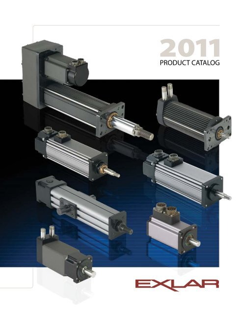
2011<br />
<strong>PRODUCT</strong> <strong>CATALOG</strong>
The Global Leader in Actuator Technology<br />
For over a decade <strong>Exlar</strong> has been the global leader in actuator technology. Our patented<br />
roller screw linear actuators have always offered the most compact, robust and durable<br />
designs – lasting up to 15 times longer than similar sized ball screws. Our T-LAM brushless<br />
motor technology provides the industry’s highest torque density which results in very<br />
compact actuators with high force and speed capabilities. We continue to expand our<br />
product lines through the use of these powerful technologies.<br />
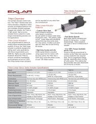
We offer three additional product families not included in this catalog. The newest, the<br />
Tritex II DC actuators, integrate a DC powered servo drive, digital position controller,<br />
brushless motor and linear or rotary actuator in one compact, sealed package. Tritex II<br />
actuators offer the ideal solution for customers needing 12-48 VDC power input.<br />
The Tritex II AC actuators integrate an AC powered servo drive, digital position controller,<br />
brushless motor and linear or rotary actuator, also in one compact, sealed package. Simply<br />
connect pwer, I/O, communications and solve your application with one integrated device.<br />
Our Extrak actuators consist of a precision aluminum frame with a movable platen.<br />
Designed for heavy duty, continuous motion applications, the Extrak products with their<br />
high speed and long stroke length capabilities make them ideal for industrial positioning or<br />
material handling applications. Please contact <strong>Exlar</strong> to receive these separate brochures. You<br />
may also visit www.exlar.com to download the brochures and view complete specifications.<br />
We invite you to review both our new and field-proven actuators to see how <strong>Exlar</strong>’s<br />
unique products will give you the most effective rotary and linear actuation for your<br />
applications. We would welcome the opportunity to discuss your requirements and make<br />
a recommendation.
Table of Contents<br />
page<br />
Roller Screw Technology.....................................................................................2<br />
Integrated Actuator Technology...............................................................3<br />
GSX Series Linear Actuators................................................................................4<br />
Performance Specifications.................................................................................. 11<br />
Drawings........................................................................................................................... 28<br />
Ordering Guide............................................................................................................. 36<br />
GSM Series Linear Actuators............................................................................ 38<br />
Performance Specifications.................................................................................. 40<br />
Drawings........................................................................................................................... 49.<br />
Ordering Guide............................................................................................................. 54<br />
I Series Linear Actuators...................................................................................... 56<br />
Performance Specifications.................................................................................. 59.<br />
Drawings........................................................................................................................... 62<br />
Ordering Guide............................................................................................................. 72<br />
FT Series Linear Actuators.................................................................................. 74<br />
Performance Specifications.................................................................................. 78<br />
Drawings........................................................................................................................... 80<br />
Ordering Guide............................................................................................................. 88<br />
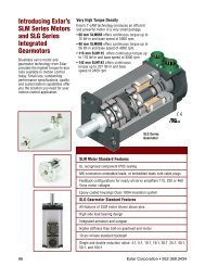
SLM and SLG Series Rotary Motors and Gearmotors......... 88<br />
Performance Specifications.................................................................................. 9.2<br />
Drawings........................................................................................................................... 9.8<br />
Ordering Guide.......................................................................................................... 106<br />
Cable selection guide........................................................................................... 108<br />
Hazardous Location EL Series Linear Actuators................ 112<br />
Performance Specifications............................................................................... 114<br />
Drawings........................................................................................................................ 117<br />
Ordering Guide.......................................................................................................... 120<br />
Hazardous Location ER Series Rotary Actuators.............. 122<br />
Performance Specifications............................................................................... 124<br />
Drawings........................................................................................................................ 126<br />
Ordering Guide.......................................................................................................... 127<br />
Hazardous Location Class I Division 2 Products<br />
GSX/GSM Series................................................................................................................. 128<br />
Drawings for GSX...................................................................................................... 130<br />
Ordering Guide for GSX........................................................................................ 134<br />
Drawings for GSM.................................................................................................... 135<br />
Ordering Guide for GSM...................................................................................... 137<br />
Hazardous Location Class I Division 2 Products<br />
SLM/SLG Series.................................................................................................................. 138<br />
Drawings for SLM..................................................................................................... 140<br />
Drawings for SLG...................................................................................................... 143<br />
Ordering Guide for SLM/SLG............................................................................. 145<br />
Engineering Reference......................................................................................... 146<br />
GSX Series<br />
GSM Series<br />
I Series<br />
FT Series<br />
SLM/SLG<br />
Series<br />
Cables<br />
EL Series<br />
ER Series<br />
CID2, GSX &<br />
GSM Series<br />
CID2, SLM &<br />
SLG Seri es
Roller Screw Technology<br />
Why Consider Roller<br />
Screw Technology<br />
Designers have five basic choices when it comes to<br />
achieving controlled linear motion. The table on page 3<br />
gives you a quick overview of what general advantages are<br />
associated with each. Because the roller screw technology<br />
common to all <strong>Exlar</strong> linear actuators might not be familiar<br />
to everyone using this catalog, allow us to present a<br />
general overview.<br />
The difference is in the roller screw’s design for transmitting<br />
forces. Multiple threaded helical rollers are assembled in<br />
a planetary arrangement around a threaded shaft (shown<br />
above), which converts a motor’s rotary motion into linear<br />
movement of the shaft or nut.<br />
Roller Screw Basics<br />
A roller screw is a mechanism for converting rotary torque<br />
into linear motion, in a similar manner to acme screws<br />
or ball screws. But, unlike those devices,<br />
roller screws can carry heavy loads for<br />
thousands of hours in the most arduous<br />
conditions. This makes roller screws the ideal choice for<br />
demanding, continuous-duty applications.<br />
Roller Screw vs Hydraulic &<br />
Pneumatic – Comparisons:<br />
In applications where high loads<br />
are anticipated or faster cycling is<br />
desired, <strong>Exlar</strong>’s roller screw actuators<br />
provide an attractive alternative to the<br />
hydraulic or pneumatic options. With<br />
their vastly simplified controls, electromechanical<br />
units using roller screws<br />
have major advantages. They do not<br />
require a complex support system of<br />
valves, pumps, filters and sensors. Thus,<br />
<strong>Exlar</strong> units take up much less space<br />
and deliver extremely long working<br />
lives with virtually no maintenance.<br />
Hydraulic fluid leaks are non-existent.<br />
Noise levels are reduced significantly.<br />
Additionally, the flexibility of computer<br />
programmed positioning can be very<br />
desirable in many applications.<br />
Roller vs Ball Screw<br />
Performance – Comparisons:<br />
Loads and Stiffness: Due to design factors, the<br />
number of contact points in a ball screw is limited<br />
by the ball size. <strong>Exlar</strong>’s planetary roller screw<br />
designs provide many more contact points than<br />
possible on comparably sized ball screws. Because<br />
this number of contact points is greater, roller<br />
screws have higher load carrying capacities, plus<br />
improved stiffness. In practical terms, this means<br />
that typically an <strong>Exlar</strong> roller screw actuator takes up much less space to<br />
meet the designer’s specified load rating.<br />
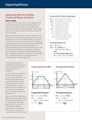
Travel Life: As you would expect, with their higher load capacities,<br />
roller screws deliver major advantages in working life Usually measured<br />
in “Inches of Travel,” the relative travel lives for roller and ball screws are<br />
displayed on the graph on page 3. As you can see there, in a 2,000 lb.<br />
average load application applied to a 1.2 inch (approximate) screw<br />
diameter with a 0.2 inch (approximate) lead, you can predict that the<br />
roller screw will have an expected service life that is 15 Times Greater.<br />
Speeds: Typical ball screw speeds<br />
are limited to 2000 rpm and less,<br />
due to the interaction of the<br />
balls colliding with each other as<br />
the race rotates. In contrast, the<br />
rollers in a roller screw are fixed in planetary fashion by journals at the<br />
ends of the nut and therefore do not have this limitation. Hence, roller<br />
screws can work at 5000 rpm and higher – producing comparably higher<br />
linear travel rates.<br />
2 9.52.500.6200 | www.exlar.com
Roller Screw Technology<br />
Lifetime Comparison (Roller vs Ball Screws)<br />
10,000<br />
Roller Screw<br />
Ball Screw<br />
Thrust Load (pounds)<br />
1,000<br />
0<br />
2000 lbf load<br />
1.2" diameter<br />
.2" lead screw<br />
comparison<br />
0 1,000,000 10,000,000 100,000,000 1,000,000,000<br />
Lifetime (Inches of Travel)<br />
Roller Screw vs. Other Linear Motion Technologies (Used in electronic positioning applications)<br />
EXLAR ROLLER SCREWS ACME SCREWS BALL SCREWS HYDRAULIC CYLINDERS PNEUMATIC CYLINDERS<br />
Load ratings Very High High High Very High High<br />
Lifetime<br />
Very long, many times<br />
greater than ball screw<br />
Very low, due to<br />
high friction & wear<br />
Moderate<br />
Can be long with<br />
proper maintenance<br />
Can be long with<br />
proper maintenance<br />
Speed Very high Low Moderate Moderate Very high<br />
Acceleration Very high Low Moderate Very high Very high<br />
Electronic Positioning Easy Moderate Easy Difficult Very Difficult<br />
Stiffness Very high Very high Moderate Very high Very low<br />
Shock Loads Very high Very high Moderate Very high High<br />
Relative Space<br />
Requirements<br />
Minimum Moderate Moderate High High<br />
Friction Low High Low High Moderate<br />
Efficiency >90% approx 40% >90%
GS Series Linear Actuators<br />
<strong>Exlar</strong> GS Series<br />
Linear Actuator Family<br />
The GS Series linear actuator family offers<br />
you two grades of actuator to provide cost<br />
effective options in order to meet your<br />
application’s requirements. View<br />
the chart below to compare<br />
the GSX and GSM models.<br />
All GS Series actuators use a<br />
specially designed roller screw mechanism<br />
for converting electric motor power into linear motion<br />
within the actuator. Planetary rollers assembled around the<br />
actuator’s extending rod follow threads which are precisely<br />
machined on the inside surface of the actuator’s hollow<br />
armature. Linear motion is produced in precise<br />
synchronization with the armature rotation. Because this<br />
roller screw mechanism has an inherently larger<br />
cumulative contact surface, these actuators have a much<br />
longer working life, and can handle heavier loads at higher<br />
speeds than is possible from a similarly sized unit built<br />
around a ball screw system.<br />
<strong>Exlar</strong>’s T-LAM segmented lamination stator technology<br />
delivers higher continuous motor torque than is available<br />
in traditionally wound motors. T-LAM technology consists<br />
of stator segments, each containing individual phase<br />
wiring for maximum motor performance. The improved<br />
efficiencies of the GSX Series are a result of the limited heat<br />
generation qualities inherent in the segmented stator<br />
design as seen above. The elimination of end turns in the<br />
stator, and use of thermally conductive potting removes<br />
the parts most susceptible to failure in a traditional stator.<br />
Other design advantages include:<br />
• Neodymium-iron-boron magnets provide high flux<br />
density and maximum motor torque.<br />
• Thermally conductive potting of the entire stator<br />
provides increased heat dissipation and provides<br />
protection from contamination in oil-cooled units.<br />
• Each stator segment contains individual phase wiring.<br />
External winding of individual segments provides<br />
maximum slot fill for maximum motor performance.<br />
• Motors with T-LAM technology have Class 180 H<br />
insulation systems compliant with UL requirements.<br />
UL recognized component.<br />
• Motors with T-LAM technology are CE compliant<br />
The Actuator & Motor, All in one Compact Unit<br />
With other actuator technologies, customers are usually<br />
responsible for engineering the completed linear motion<br />
system. This usually includes purchasing the motor, gear<br />
reducer, timing belt, mounting hardware, flexible<br />
couplings, etc. separately. Then they all must be<br />
assembled to perform properly in a given application.<br />
GS Series actuators eliminate all this systems engineering.<br />
These units are single, fully integrated component<br />
packages – much smaller than traditional rotary-to-linear<br />
conversion mechanisms.<br />
Designed for Closed Loop Servo Systems<br />
Their brushless servo design means GS Series units can be<br />
used in advanced closed-loop servo systems when velocity<br />
and positioning is required. Position feedback can be<br />
delivered in a number of different firms. These include<br />
resolvers, encoders or internally mounted linear position<br />
feedback sensors.<br />
GSX and GSM Differences GSX (pg 4) GSM (pg 38)<br />
Ingress Protection IP65 IP54 (IP65 optional)<br />
No. of Stacks 1, 2, 3 1, 2<br />
Life BSY (Ball Screw Years) 15X 2 to 5X<br />
Oil Cooling Yes No<br />
Food Grade Paint Yes No<br />
Electroless Nickel Housing Yes Yes<br />
Stainless Steel Case Yes No<br />
Hard Coat Anodized Yes Yes<br />
LVDT FB<br />
Lamination<br />
Endcaps<br />
Yes<br />
(except 2" frame)<br />
Individual<br />
Segments<br />
Yes<br />
(except 2" frame)<br />
5.5 in. Frame Yes No<br />
7 in. Frame Yes No<br />
Force (lbf) 92 - 15,000 92 - 3,966<br />
1.0 Lead 50 & 60 only No<br />
Rear Brake all all<br />
Speeds (ips) 5 - 40 5 - 37.5<br />
Electroless Nickel Connectors Yes Yes<br />
4 9.52.500.6200 | www.exlar.com
GSX Series Linear Actuators<br />
<strong>Exlar</strong> GSX Series<br />
The Highest Performance<br />
and Longest Life Solution<br />
GSX Series<br />
For applications that require long life and continuous<br />
duty, even in harsh environments the GSX Series<br />
actuator offers a robust solution. The life of the GSX<br />
Series can exceed that of a ball screw actuator<br />
by 15X while delivering high speeds and<br />
high forces. This compact package has all<br />
the advantages that our GS Series offers.<br />
Sealed for Long Life with<br />
Minimum Maintenance<br />
GSX Series actuators have strong advantages whenever<br />
outside contaminants are an issue. In most rotary-tolinear<br />
devices, critical mechanisms are exposed to the<br />
environment. Thus, they must be frequently inspected,<br />
cleaned and lubricated.<br />
In contrast, the converting components in all <strong>Exlar</strong> GSX<br />
units are mounted within the sealed motor housing.<br />
With a simple bushing and seal arrangement on the<br />
smooth extending rod, abrasive particles or other<br />
contaminants are prevented from reaching the<br />
actuator’s critical mechanisms. This assures trouble-free<br />
operation even in the most harsh environments.<br />
Lubrication requirements are minimal. GSX actuators<br />
can be lubricated with either grease or recirculated oil.<br />
Grease lubricated units will run up to 10,000 hours<br />
without regreasing. Recirculated oil systems eliminate<br />
this type of maintenance altogether A GSX Series<br />
actuator with a properly operating recirculating oil<br />
system will operate indefinitely without any other<br />
lubrication requirements.<br />
Available in Five Frame Sizes<br />
2" GSX20 3" GSX30 4" GSX40<br />
5" GSX50 7" GSX60<br />
If you need a custom design, <strong>Exlar</strong>’s Application<br />
Engineering department will work with you to engineer<br />
a solution specifically tailored to your application.<br />
Feature Standard Optional<br />
External anti-rotate<br />
mechanism<br />
No<br />
Yes<br />
Internal Anti-rotate No Yes<br />
Pre-loaded follower No Yes<br />
Electric brake No Yes<br />
External End switches No Yes<br />
Connectors<br />
Mounting Style<br />
Rod End<br />
Lubrication<br />
Primary Feedback<br />
Absolute Linear<br />
Feedback<br />
MS or Threaded Circular<br />
Style Connectors<br />
Extended Tie Rods, Side Tapped<br />
Mounting Holes, Trunnion, Rear<br />
Clevis, Front or Rear Flange<br />
Male or Female:<br />
U.S. Standard or Metric<br />
Greased, Oil Connection<br />
Ports are Built-in for Customer<br />
Supplied Recirculated<br />
Oil Lubrication<br />
Standard Encoders or<br />
Resolvers to Meet Most<br />
Amplifier Requirements<br />
No<br />
Electroless Nickel Connectors/<br />
Male NPT with Potted Leads/<br />
Manufacturers Connectors<br />
Custom Mountings<br />
Specials Available To Meet<br />
OEM Requirements<br />
Specials Available To Meet<br />
OEM Requirements<br />
Custom Feedback<br />
ICT, including signal conditioner<br />
9.52.500.6200 | www.exlar.com 5
GSX Series Linear Actuators<br />
<strong>Exlar</strong> GSX Series Linear Actuators Applications Include:<br />
Hydraulic cylinder<br />
replacement<br />
Ball screw replacement<br />
Pneumatic cylinder<br />
replacement<br />
Chip and wafer handling<br />
Automated flexible fixturing<br />
Dispensers<br />
Machine tool<br />
Automated assembly<br />
Parts clamping<br />
Automatic tool changers<br />
Volumetric pumps<br />
Medical equipment<br />
Conveyor diverters / gates<br />
Plastics equipment<br />
Cut-offs<br />
Die cutters<br />
Packaging machinery<br />
Entertainment<br />
Sawmill equipment<br />
Open / close doors<br />
Fillers<br />
Formers<br />
Precision grinders<br />
Indexing stages<br />
Lifts<br />
Product sorting<br />
Material cutting<br />
Material handling<br />
Riveting / fastening / joining<br />
Molding<br />
Volumetric pumps<br />
Semiconductor<br />
Pick and place systems<br />
Robot manipulator arms<br />
Simulators<br />
Precision valve control<br />
Ventilation control<br />
systems<br />
Pressing<br />
Process control<br />
Tube bending<br />
Welding<br />
Stamping<br />
Test stands<br />
Tension control<br />
Web guidance<br />
Wire winding<br />
Food Processing<br />
Repeatable force,<br />
reliable positioning<br />
accuracy, and flexible<br />
control make GSX<br />
actuators a perfect fit<br />
for assembly presses<br />
or test stands.<br />
Because they cycle<br />
quickly and can be<br />
synchronized to line<br />
speeds, <strong>Exlar</strong> actuators<br />
produce dramatic<br />
improvements in web<br />
control applications.<br />
Repeatable force control plus positioning<br />
accuracy extends the life of costly tools<br />
when <strong>Exlar</strong> linear actuators are used in<br />
precision clamping applications.<br />
In clean room applications<br />
like those common to<br />
semiconductor manufacturing,<br />
the compact design of our GSX<br />
Series saves critical space.<br />
6 9.52.500.6200 | www.exlar.com
GSX Series Linear Actuators<br />
GSX Series Speed vs. Force Curves<br />
These charts represent typical linear speed versus linear<br />
force curves for the GSX actuators using common brushless<br />
motor amplifiers. The GSX Series are compatible with many<br />
different brushless motor amplifiers, and differences in the<br />
performance ratings of these amplifiers can alter the<br />
actuator’s performance. Thus, the curves below should be<br />
used for estimation only (Further information is available by<br />
contacting <strong>Exlar</strong> Application Engineering.)<br />
GSX Series<br />
Force lbf (N)<br />
Force lbf (N)<br />
Force lbf (N)<br />
700<br />
(3114)<br />
600<br />
(2669)<br />
500<br />
(2224)<br />
400<br />
(1779)<br />
300<br />
(1334)<br />
200<br />
(890)<br />
100<br />
(445)<br />
0<br />
400<br />
(1779)<br />
350<br />
(1557)<br />
300<br />
(1334)<br />
250<br />
(1112)<br />
200<br />
(890)<br />
150<br />
(667)<br />
100<br />
(445)<br />
50<br />
(222)<br />
0<br />
200<br />
(890)<br />
150<br />
(667)<br />
100<br />
(445)<br />
50<br />
(222)<br />
0<br />
GSX20-.1 Inch Lead<br />
Speed inch/sec (mm/sec)<br />
Speed inch/sec (mm/sec)<br />
Speed inch/sec (mm/sec)<br />
1X8<br />
2X8<br />
0 1 2 3 4 5 6 7 8 9<br />
(25.4) (50.8) (76.2) (101.6) (127) (152.4) (177.8) (203.2) (278.6)<br />
GSX20-.2 Inch Lead<br />
1X8<br />
2X8<br />
3X8<br />
0 2 4 6 8 10 12 14 16 18<br />
(50.8) (101.6) (152.4) (203.2) (254) (304.8) (356) (406.4) (457.2)<br />
GSX20-.4 Inch Lead<br />
0 5 10 15 20 25 30 35<br />
(127) (254) (381) (508) (635) (762) (889)<br />
Force lbf (N)<br />
Force lbf (N)<br />
Force lbf (N)<br />
2000<br />
(8896)<br />
1800<br />
(8007)<br />
1600<br />
(7117)<br />
1400<br />
(6228)<br />
1200<br />
(5338)<br />
1000<br />
(4448)<br />
800<br />
(3559)<br />
600<br />
(2669)<br />
400<br />
(1779)<br />
200<br />
(890)<br />
0<br />
1000<br />
(4448)<br />
900<br />
(4003)<br />
800<br />
(3559)<br />
700<br />
(3114)<br />
600<br />
(2669)<br />
500<br />
(2224)<br />
400<br />
(1779)<br />
300<br />
(1334)<br />
200<br />
(890)<br />
100<br />
(445)<br />
0<br />
450<br />
(2002)<br />
400<br />
(1779)<br />
350<br />
(1557)<br />
300<br />
(1334)<br />
250<br />
(1112)<br />
200<br />
(890)<br />
150<br />
(667)<br />
100<br />
(445)<br />
50<br />
(222)<br />
0<br />
GSX30-.1 Inch Lead<br />
0 1 2 3 4 5 6<br />
(25.4) (50.8) (76.2) (101.6) (127) (152.4)<br />
Speed inch/sec (mm/sec)<br />
GSX30-.2 Inch Lead<br />
0 2 4 6 8 10 12<br />
(50.8) (101.6) (152.4) (203.2) (254) (304.8)<br />
Speed inch/sec (mm/sec)<br />
GSX30-.5 Inch Lead<br />
0 5 10 15 20 25 30<br />
(127) (254) (381) (508) (635) (762)<br />
Speed inch/sec (mm/sec)<br />
Test data derived using NEMA recommended aluminum heatsink 10" x 10" x 1/4" for GSX20 and 10" x 10" x 3/8" for GSX30<br />
9.52.500.6200 | www.exlar.com 7
GSX Series Linear Actuators<br />
GSX Series Speed vs. Force Curves<br />
Force lbf (N)<br />
6000<br />
(26689)<br />
5000<br />
(22241)<br />
4000<br />
(17793)<br />
3000<br />
(13345)<br />
2000<br />
(8896)<br />
1000<br />
(4448)<br />
0<br />
GSX40-.1 Inch Lead<br />
0 1 2 3 4 5 6<br />
(25.4) (50.8) (76.2) (101.6) (127) (152.4)<br />
Speed inch/sec (mm/sec)<br />
Force lbf (N)<br />
9000<br />
(40034)<br />
8000<br />
(35586)<br />
7000<br />
(31138)<br />
6000<br />
(26689)<br />
5000<br />
(22241)<br />
4000<br />
(17793)<br />
3000<br />
(13345)<br />
2000<br />
(8896)<br />
1000<br />
GSX50-.1 Inch Lead<br />
Speed inch/sec (mm/sec)<br />
1X8<br />
2X8<br />
0 1 2 3 4 6<br />
(25.4) (50.8) (76.2) (101.6) (152.4)<br />
(4448)<br />
0<br />
Speed inch/sec (mm/sec)<br />
Force lbf (N)<br />
Force lbf (N)<br />
Force lbf (N)<br />
3000<br />
(13345)<br />
2500<br />
(11121)<br />
2000<br />
(8896)<br />
1500<br />
(6672)<br />
1000<br />
(4448)<br />
500<br />
(2224)<br />
0<br />
1200<br />
(5338)<br />
1000<br />
(4448)<br />
800<br />
(3559)<br />
600<br />
(2669)<br />
400<br />
(1779)<br />
200<br />
(890)<br />
0<br />
800<br />
(3559)<br />
700<br />
(3114)<br />
600<br />
(2669)<br />
500<br />
(2224)<br />
400<br />
(1779)<br />
300<br />
(1334)<br />
200<br />
(890)<br />
100<br />
(445)<br />
0<br />
GSX40-.2 Inch Lead<br />
Speed inch/sec (mm/sec)<br />
1X8<br />
2X8<br />
3X8<br />
0 2 4 6 8 10 12<br />
(50.8) (101.6) (152.4) (203.2) (254) (304.8)<br />
GSX40-.5 Inch Lead<br />
Speed inch/sec (mm/sec)<br />
1X8<br />
2X8<br />
3X8<br />
0 5 10 15 20 25 30<br />
127 254 381 508 635 762<br />
GSX40-.75 Inch Lead<br />
Speed inch/sec (mm/sec)<br />
1X8<br />
2X8<br />
3X8<br />
0 5 10 15 20 25 30 35 40<br />
(127) (254) (381) (508) (635) (762) (889) (1016)<br />
Force lbf (N)<br />
Force lbf (N)<br />
Force lbf (N)<br />
6000<br />
(26689)<br />
5000<br />
(22241)<br />
4000<br />
(17793)<br />
3000<br />
(13345)<br />
2000<br />
(8896)<br />
1000<br />
(4448)<br />
0<br />
2500<br />
(11121)<br />
2000<br />
(8896)<br />
1500<br />
(6672)<br />
1000<br />
(4448)<br />
500<br />
(2224)<br />
0<br />
1200<br />
(5338)<br />
1000<br />
(4448)<br />
800<br />
(3559)<br />
600<br />
(2669)<br />
400<br />
(1779)<br />
200<br />
(890)<br />
0<br />
GSX50-.2 Inch Lead<br />
1X8<br />
2X8<br />
3X8<br />
0 2 4 6 8 10<br />
(50.8) (101.6) (152.4) (203.2) (254)<br />
GSX50-.5 Inch Lead<br />
Speed inch/sec (mm/sec)<br />
1X8<br />
2X8<br />
3X8<br />
0 5 10 15 20 25<br />
(127) (254) (381) (508) (635)<br />
GSX50-1.0 Inch Lead<br />
Speed inch/sec (mm/sec)<br />
1X8<br />
2X8<br />
3X8<br />
0 10 20 30 40 50<br />
(254) (508) (762) (1016) (1270)<br />
Test data derived using NEMA recommended aluminum heatsink 12" x 12" x 1/2" for GSX40 and 12" x 12" x 1/2" for GSX50<br />
8 9.52.500.6200 | www.exlar.com
GSX Series Linear Actuators<br />
GSX Series Speed vs. Force Curves<br />
These charts represent typical linear speed versus linear<br />
force curves for GSX actuators using common brushless<br />
motor amplifiers. The GSX Series are compatible with many<br />
different brushless motor amplifiers, and differences in the<br />
performance ratings of these amplifiers can alter the<br />
actuator’s performance. Thus, the curves below should be<br />
used for estimation only. (Further information is available<br />
by contacting <strong>Exlar</strong> Application Engineering.)<br />
GSX Series<br />
Force lbf (N)<br />
14000<br />
(62275)<br />
12000<br />
(53379)<br />
10000<br />
(44482)<br />
8000<br />
(35586)<br />
6000<br />
(26689)<br />
4000<br />
(17793)<br />
2000<br />
(8896)<br />
0<br />
GSX60-.25 Inch Lead<br />
Speed inch/sec (mm/sec)<br />
1X8<br />
2X8<br />
3X8<br />
0 2 4 6 8 10 12<br />
(50.8) (101.6) (152.4) (203.2) (254) (304.8)<br />
Force lbf (N)<br />
7000<br />
(31138)<br />
6000<br />
(26689)<br />
5000<br />
(22241)<br />
4000<br />
(17793)<br />
3000<br />
(13345)<br />
2000<br />
(8896)<br />
1000<br />
(4448)<br />
0<br />
GSX60-.5 Inch Lead<br />
Speed inch/sec (mm/sec)<br />
1X8<br />
2X8<br />
3X8<br />
0 5 10 15 20 25<br />
(127) (254) (381) (508) (635)<br />
Force lbf (N)<br />
3500<br />
(15569)<br />
3000<br />
(13345)<br />
2500<br />
(11121)<br />
2000<br />
(8896)<br />
1500<br />
(6672)<br />
1000<br />
(4448)<br />
500<br />
(2224)<br />
0<br />
GSX60-1.0 Inch Lead<br />
Speed inch/sec (mm/sec)<br />
1X8<br />
2X8<br />
3X8<br />
0 10 20 30 40 50<br />
(254) (508) (762) (1016) (1270)<br />
9.52.500.6200 | www.exlar.com 9
GSX Series Linear Actuators<br />
GSX Series Lifetime Curves<br />
The L 10 expected life of a roller screw linear actuator is<br />
expressed as the linear travel distance that 9.0% of properly<br />
maintained roller screws manufactured are expected to meet<br />
or exceed. For higher than 9.0% reliability, the result should be<br />
multiplied by the following factors: 9.5% x 0.62; 9.6% x 0.53;<br />
9.7% x 0.44; 9.8% x 0.33; 9.9.% x 0.21. This is not a guarantee and<br />
these charts should be used for estimation purposes only.<br />
The underlying formula that defines this value is:<br />
Travel life in millions of inches, where:<br />
C = Dynamic load rating (lbf )<br />
F = Cubic mean applied load (lbf )<br />
S = Roller screws lead (inches)<br />
L 10<br />
= (<br />
C<br />
) 3 x S =<br />
F<br />
All curves represent properly lubricated and maintained actuators.<br />
Mean Load pounds (N)<br />
Mean Load pounds (N)<br />
1200<br />
(5338)<br />
1000<br />
(4448)<br />
800<br />
(3559)<br />
600<br />
(2669)<br />
400<br />
(1779)<br />
200<br />
(890)<br />
6,000<br />
(26689)<br />
5,500<br />
(24465)<br />
5,000<br />
(22241)<br />
4,500<br />
(20017)<br />
4,000<br />
(17793)<br />
3,500<br />
(15569)<br />
3,000<br />
(13345)<br />
2,500<br />
(11121)<br />
2,000<br />
(8896)<br />
GSX20<br />
0<br />
1 10 100 1,000 10,000 100,000<br />
(254) (2,540) (25,400) (254,000) (2,540,000)<br />
Travel Life Millions of inches (mm)<br />
GSX40<br />
GSX40-xx01<br />
GSX40-xx02<br />
GSX40-xx05<br />
GSX40-xx08<br />
1,500<br />
(6672)<br />
1,000<br />
(4448)<br />
500<br />
(2224)<br />
0<br />
1 10 100 1,000 10,000 100,000<br />
(254) (2,540) (25,400) (254,000) (2,540,000)<br />
Travel Life Millions of inches (mm)<br />
Mean Load pounds (N)<br />
14,000<br />
(62275)<br />
12,000<br />
(53379)<br />
10,000<br />
(44482)<br />
8,000<br />
(35586)<br />
6,000<br />
(26689)<br />
4,000<br />
(17793)<br />
2,000<br />
(8896)<br />
0<br />
GSX20-xx01<br />
GSX20-xx02<br />
GSX20-xx04<br />
Mean Load pounds (N)<br />
Mean Load pounds (N)<br />
4,500<br />
(20017)<br />
4,000<br />
(17793)<br />
3,500<br />
(15569)<br />
3,000<br />
(13345)<br />
2,500<br />
(11121)<br />
2,000<br />
(8896)<br />
1,500<br />
(6672)<br />
1,000<br />
(4448)<br />
500<br />
(2224)<br />
0<br />
9,000<br />
(40034)<br />
8,000<br />
(35586)<br />
7,000<br />
(31138)<br />
6,000<br />
(26689)<br />
5.000<br />
(22241)<br />
4,000<br />
(17793)<br />
3,000<br />
(13345)<br />
2,000<br />
(8896)<br />
1,000<br />
(4448)<br />
0<br />
GSX60<br />
GSX60-xx03<br />
GSX60-xx05<br />
GSX60-xx10<br />
1 10 100 1,000 10,000 100,000<br />
(254) (2,540) (25,400) (254,000) (2,540,000)<br />
Travel Life Millions of inches (mm)<br />
GSX30<br />
GSX30-xx01<br />
GSX30-xx02<br />
GSX30-xx05<br />
1 10 100 1,000 10,000 100,000<br />
(254) (2,540) (25,400) (254,000) (2,540,000)<br />
Travel Life Millions of inches (mm)<br />
GSX50<br />
GSX50-xx01<br />
GSX50-xx02<br />
GSX50-xx05<br />
GSX50-xx10<br />
1 10 100 1,000 10,000 100,000<br />
(254) (2,540) (25,400) (254,000) (2,540,000)<br />
Travel Life Millions of inches (mm)<br />
10 9.52.500.6200 | www.exlar.com
GSX Series Linear Actuators<br />
GSX20 & GSX30 Performance Specifications<br />
Model No.<br />
GSX20-0301<br />
GSX20-0302<br />
GSX20-0304<br />
Frame<br />
Size<br />
in (mm)<br />
2.25<br />
(57)<br />
Stroke<br />
(nominal)*<br />
in (mm)<br />
3<br />
(75)<br />
Screw Lead<br />
in (mm)<br />
0.1<br />
(2.54)<br />
0.2<br />
(5.08)<br />
0.4<br />
(10.16)<br />
Continuous<br />
Force Rating<br />
lb (N) 1/2/3 stack<br />
367/578/NA<br />
(1632/2571/NA)<br />
183/289/NA<br />
(814/1286/NA)<br />
92/145/NA<br />
(409/645/NA)<br />
Max Velocity<br />
in/sec<br />
(mm/sec)<br />
8.33<br />
(211.67)<br />
16.77<br />
(423.33)<br />
33.33<br />
(846.67)<br />
Continuous<br />
Motor Torque<br />
lb-in (N-m)<br />
7.3/11.5/NA<br />
(0.82/1.30/NA)<br />
7.3/11.5/NA<br />
(0.82/1.30/NA)<br />
7.3/11.5/NA<br />
(0.82/1.30/NA)<br />
Maximum<br />
Static Load<br />
lb (N)<br />
1250<br />
(5560)<br />
Armature<br />
Inertia**<br />
lb-in-s 2 (Kg-m 2 )<br />
0.00101<br />
(0.000114)<br />
Dynamic<br />
Load Rating<br />
lb (N)<br />
2075<br />
(9230)<br />
1540<br />
(6850)<br />
1230<br />
(5471)<br />
Weight<br />
(approx.)<br />
lb (kg)<br />
6.5<br />
(2.9)<br />
GSX Series<br />
GSX20-0601<br />
GSX20-0602<br />
GSX20-0604<br />
2.25<br />
(57)<br />
6<br />
(150)<br />
0.1<br />
(2.54)<br />
0.2<br />
(5.08)<br />
0.4<br />
(10.16)<br />
367/578/NA<br />
(1632/2571/NA)<br />
183/289/385<br />
(814/1286/1713)<br />
92/145/192<br />
(409/645/854)<br />
8.33<br />
(211.67)<br />
16.67<br />
(423.33)<br />
33.33<br />
(846.67)<br />
7.3/11.5/NA<br />
(0.82/1.30/NA)<br />
7.3/11.5/15.3<br />
(0.82/1.30/1.73)<br />
7.3/11.5/15.3<br />
(0.82/1.30/1.73)<br />
1250<br />
(5560)<br />
0.00114<br />
(0.000129)<br />
2075<br />
(9230)<br />
1540<br />
(6850)<br />
1230<br />
(5471)<br />
8.0<br />
(3.6)<br />
GSX20-1001<br />
GSX20-1002<br />
GSX20-1004<br />
2.25<br />
(57)<br />
10<br />
(250)<br />
0.1<br />
(2.54)<br />
0.2<br />
(5.08)<br />
0.4<br />
(10.16)<br />
367/578/NA<br />
(1632/2571/NA)<br />
183/289/385<br />
(814/1286/1713)<br />
92/145/192<br />
(409/645/854)<br />
8.33<br />
(211.67)<br />
16.67<br />
(423.33)<br />
33.33<br />
(846.67)<br />
7.3/11.5/NA<br />
(0.82/1.30/NA)<br />
7.3/11.5/15.3<br />
(0.82/1.30/1.73)<br />
7.3/11.5/15.3<br />
(0.82/1.30/1.73)<br />
1250<br />
(5560)<br />
0.00133<br />
(0.000150)<br />
2075<br />
(9230)<br />
1540<br />
(6850)<br />
1230<br />
(5471)<br />
9.5<br />
(4.3)<br />
GSX20-1201<br />
GSX20-1202<br />
GSX20-1204<br />
2.25<br />
(57)<br />
12<br />
(300)<br />
0.1<br />
(2.54)<br />
0.2<br />
(5.08)<br />
0.4<br />
(10.16)<br />
367/578/NA<br />
(1632/2571/NA)<br />
183/289/385<br />
(814/1286/1713)<br />
92/145/192<br />
(409/645/854)<br />
8.33<br />
(211.67)<br />
16.67<br />
(423.33)<br />
33.33<br />
(846.67)<br />
7.3/11.5/NA<br />
(0.82/1.30/NA)<br />
7.3/11.5/15.3<br />
(0.82/1.30/1.73)<br />
7.3/11.5/15.3<br />
(0.82/1.30/1.73)<br />
1250<br />
(5560)<br />
0.00143<br />
(0.000162)<br />
2075<br />
(9230)<br />
1540<br />
(6850)<br />
1230<br />
(5471)<br />
11.0<br />
(4.9)<br />
GSX30-0301<br />
GSX30-0302<br />
GSX30-0305<br />
3.125<br />
(79)<br />
3<br />
(75)<br />
0.1<br />
(2.54)<br />
0.2<br />
(5.08)<br />
0.5<br />
12.7)<br />
829/1347/NA<br />
(3688/5992/NA)<br />
415/674/NA<br />
(1846/2998/NA)<br />
166/269/NA<br />
(738/1197/NA)<br />
5<br />
(127)<br />
10<br />
(254)<br />
25<br />
(635)<br />
16.5/26.8/NA<br />
(1.86/3.03/NA)<br />
16.5/26.8/NA<br />
(1.86/3.03/NA)<br />
16.5/26.8/NA<br />
(1.86/3.03/NA)<br />
2700<br />
(12010)<br />
0.00319<br />
(0.000360)<br />
5516<br />
(24536)<br />
5800<br />
(25798)<br />
4900<br />
(21795)<br />
9.5<br />
(4.3)<br />
GSX30-0601<br />
GSX30-0602<br />
GSX30-0605<br />
3.125<br />
(79)<br />
5.9<br />
(150)<br />
0.1<br />
(2.54)<br />
0.2<br />
(5.08)<br />
0.5<br />
(12.7)<br />
829/1347/NA<br />
(3688/5992/NA)<br />
415/674/905<br />
(1846/2998/4026)<br />
166/269/362<br />
(738/1197/1610)<br />
5<br />
(127)<br />
10<br />
(254)<br />
25<br />
(635)<br />
16.5/26.8/NA<br />
(1.86/3.03/NA<br />
16.5/26.8/36<br />
(1.86/3.03/4.07)<br />
16.5/26.8/36<br />
(1.86/3.03/4.07)<br />
2700<br />
(12010)<br />
0.00361<br />
(0.000408)<br />
5516<br />
(24536)<br />
5800<br />
(25798)<br />
4900<br />
(21795)<br />
11.5<br />
(5.2)<br />
GSX30-1001<br />
GSX30-1002<br />
GSX30-1005<br />
3.125<br />
(79)<br />
10<br />
(250)<br />
0.1<br />
(2.54)<br />
0.2<br />
(5.08)<br />
0.5<br />
(12.7)<br />
829/1347/NA<br />
(3688/5992/NA)<br />
415/674/905<br />
(1846/2998/4026)<br />
166/269/362<br />
(738/1197/1610)<br />
5<br />
(127)<br />
10<br />
(254)<br />
25<br />
(635)<br />
16.5/26.8/NA<br />
(1.86/3.03/NA)<br />
16.5/26.8/36<br />
(1.86/3.03/4.07)<br />
16.5/26.8/36<br />
(1.86/3.03/4.07)<br />
2700<br />
(12010)<br />
0.00416<br />
(0.00047)<br />
5516<br />
(24536)<br />
5800<br />
(25798)<br />
4900<br />
(21795)<br />
19<br />
(8.6)<br />
GSX30-1201<br />
GSX30-1202<br />
GSX30-1205<br />
3.125<br />
(79)<br />
12<br />
(305)<br />
0.1<br />
(2.54)<br />
0.2<br />
(5.08)<br />
0.5<br />
(12.7)<br />
829/1347/NA<br />
(3688/5992/NA)<br />
415/674/905<br />
(1846/2998/4026)<br />
166/269/362<br />
(738/1197/1610)<br />
5<br />
(127)<br />
10<br />
(254)<br />
25<br />
(635)<br />
16.5/26.8/NA<br />
(1.86/3.03/NA)<br />
16.5/26.8/36<br />
(1.86/3.03/4.07)<br />
16.5/26.8/36<br />
(1.86/3.03/4.07)<br />
2700<br />
(12010)<br />
0.00443<br />
(0.000501)<br />
5516<br />
(24536)<br />
5800<br />
(25798)<br />
4900<br />
(21795)<br />
20.5<br />
(9.3)<br />
GSX30-1401<br />
GSX30-1402<br />
GSX30-1405<br />
3.125<br />
(79)<br />
14<br />
(355)<br />
0.1<br />
(2.54)<br />
0.2<br />
(5.08)<br />
0.5<br />
(12.7)<br />
829/1347/NA<br />
(3688/5992/NA)<br />
415/674/905<br />
(1846/2998/4026)<br />
166/269/362<br />
(738/1197/1610)<br />
5<br />
(127)<br />
10<br />
(254)<br />
25<br />
(635)<br />
16.5/26.8/NA<br />
(1.86/3.03/NA)<br />
16.5/26.8/36<br />
(1.86/3.03/4.07)<br />
16.5/26.8/36<br />
(1.86/3.03/4.07)<br />
2700<br />
(12010)<br />
0.00473<br />
(0.000534)<br />
5516<br />
(24536)<br />
5800<br />
(25798)<br />
4900<br />
(21795)<br />
20.5<br />
(9.3)<br />
GSX30-1801<br />
0.1<br />
(2.54)<br />
829/1347/NA<br />
(3688/5992/NA)<br />
5<br />
(127)<br />
16.5/26.8/36<br />
(1.86/3.03/4.07)<br />
5516<br />
(24536)<br />
GSX30-1802<br />
3.125<br />
(79)<br />
18<br />
(457)<br />
0.2<br />
(5.08)<br />
415/674/905<br />
(1846/2998/4026)<br />
10<br />
(254)<br />
16.5/26.8/36<br />
(1.86/3.03/4.07)<br />
2700<br />
(12010)<br />
0.00533<br />
(0.000602)<br />
5800<br />
(25798)<br />
25<br />
(11.3)<br />
GSX30-1805<br />
0.5<br />
(12.7)<br />
166/269/362<br />
(738/1197/1610)<br />
25<br />
(635)<br />
16.5/26.8/36<br />
(1.86/3.03/4.07)<br />
4900<br />
(21795)<br />
* Please note that stroke mm are nominal dimensions. **Inertia +/– 5% Specifications subject to change without notice.<br />
See page 13 for definition of terms.<br />
9.52.500.6200 | www.exlar.com 11
GSX40 Series Linear Actuators<br />
GSX40 Performance Specifications<br />
Model No.<br />
GSX40-0601<br />
Frame Size<br />
in (mm)<br />
Stroke<br />
(nominal)*<br />
in (mm)<br />
Screw Lead<br />
in (mm)<br />
0.1<br />
(2.54)<br />
Continuous<br />
Force Rating<br />
lb (N) 1/2/3 stack<br />
2393/3966/NA<br />
(10645/17642/NA)<br />
Max Velocity<br />
in/sec (mm/sec)<br />
5<br />
(127)<br />
Continuous<br />
Motor Torque<br />
lb-in (N-m)<br />
Maximum<br />
Static Load<br />
lb (N)<br />
Armature<br />
Inertia**<br />
lb-in-s 2 (Kg-m 2 )<br />
Dynamic<br />
Load Rating<br />
lb (N)<br />
7900<br />
(35141)<br />
Weight<br />
(approx.)<br />
lb (kg)<br />
GSX40-0602<br />
GSX40-0605<br />
3.9<br />
(99)<br />
6<br />
(150)<br />
0.2<br />
(5.08)<br />
0.5<br />
(12.7)<br />
1196/1983/NA<br />
(5320/8821/NA)<br />
479/793/NA<br />
(2131/3527/NA)<br />
10<br />
(254)<br />
25<br />
(635)<br />
47.6/78.9/NA<br />
(5.38/8.91/NA)<br />
5400<br />
(24020)<br />
0.0152<br />
( 0.001717)<br />
8300<br />
(36920)<br />
7030<br />
(31271)<br />
20<br />
(9.1)<br />
GSX40-0608<br />
0.75<br />
(19.05)<br />
319/529/NA<br />
(1419/2353/NA)<br />
37.5<br />
(953)<br />
6335<br />
(28179)<br />
GSX40-0801<br />
0.1<br />
(2.54)<br />
2393/3966/NA<br />
(10645/17642/NA)<br />
5<br />
(127)<br />
7900<br />
(35141)<br />
GSX40-0802<br />
GSX40-0805<br />
3.9<br />
(99)<br />
8<br />
(200)<br />
0.2<br />
(5.08)<br />
0.5<br />
(12.7)<br />
1196/1983/2692<br />
(5320/8821/11975)<br />
479/793/1077<br />
(2131/3527/4791)<br />
10<br />
(254)<br />
25<br />
(635)<br />
47.6/78.9/107.1<br />
(5.38/8.91/12.1)<br />
5400<br />
(24020)<br />
0.0163<br />
( 0.001842)<br />
8300<br />
(36920)<br />
7030<br />
(31271)<br />
24<br />
(10.9)<br />
GSX40-0808<br />
0.75<br />
(19.05)<br />
319/529/718<br />
(1419/2353/3194)<br />
37.5<br />
(953)<br />
6335<br />
(28179)<br />
GSX40-1001<br />
0.1<br />
(2.54)<br />
2393/3966/NA<br />
(10645/17642/NA)<br />
5<br />
(127)<br />
7900<br />
(35141)<br />
GSX40-1002<br />
GSX40-1005<br />
3.9<br />
(99)<br />
10<br />
(250)<br />
0.2<br />
(5.08)<br />
0.5<br />
(12.7)<br />
1196/1983/2692<br />
(5320/8821/11975)<br />
479/793/1077<br />
(2131/3527/4791)<br />
10<br />
(254)<br />
25<br />
(635)<br />
47.6/78.9/107.1<br />
(5.38/8.91/12.1)<br />
5400<br />
(24020)<br />
0.0175<br />
(0.001977)<br />
8300<br />
(36920)<br />
7030<br />
(31271)<br />
28<br />
(12.7)<br />
GSX40-1008<br />
0.75<br />
(19.05)<br />
319/529/718<br />
(1419/2353/3194)<br />
37.5<br />
(953)<br />
6335<br />
(28179)<br />
GSX40-1201<br />
0.1<br />
(2.54)<br />
2393/3966/NA<br />
(10645/17642/NA)<br />
5<br />
(127)<br />
7900<br />
(35141)<br />
GSX40-1202<br />
GSX40-1205<br />
3.9<br />
(99)<br />
12<br />
(305)<br />
0.2<br />
(5.08)<br />
0.5<br />
(12.7)<br />
1196/1983/2692<br />
(5320/8821/11975)<br />
479/793/1077<br />
(2131/3527/4791)<br />
10<br />
(254)<br />
25<br />
(635)<br />
47.6/78.9/107.1<br />
(5.38/8.91/12.1)<br />
5400<br />
(24020)<br />
0.0186<br />
( 0.002102)<br />
8300<br />
(36920)<br />
7030<br />
(31271)<br />
32<br />
(14.5)<br />
GSX40-1208<br />
0.75<br />
(19.05)<br />
319/529/718<br />
(1419/2353/3194)<br />
37.5<br />
(953)<br />
6335<br />
(28179)<br />
GSX40-1801<br />
GSX40-1802<br />
3.9<br />
(99)<br />
18<br />
(457)<br />
0.1<br />
(2.54)<br />
0.2<br />
(5.08)<br />
2393/3966/NA<br />
(10645/17642/NA)<br />
1196/1983/2692<br />
(5320/8821/11975)<br />
5<br />
(127)<br />
10<br />
(254)<br />
47.6/78.9/107.1<br />
(5.38/8.91/12.1)<br />
5400<br />
(24020)<br />
0.022<br />
(0.002486)<br />
7900<br />
(35141)<br />
8300<br />
(36920)<br />
44<br />
(20)<br />
GSX40-1805<br />
0.5<br />
(12.7)<br />
479/793/1077<br />
(2131/3527/4791)<br />
25<br />
(635)<br />
7030<br />
(31271)<br />
* Please note that stroke mm are nominal dimensions. **Inertia +/– 5% Specifications subject to change without notice.<br />
See page 13 for definition of terms.<br />
12 9.52.500.6200 | www.exlar.com
GSX50 & GSX60 Series Linear Actuators<br />
GSX50 & GSX60 Performance Specifications<br />
Model No.<br />
GSX50-0601<br />
GSX50-0602<br />
GSX50-0605<br />
Frame<br />
Size<br />
in (mm)<br />
5.5<br />
(140)<br />
Stroke<br />
(nominal)*<br />
in (mm)<br />
6<br />
(150)<br />
Screw Lead<br />
in (mm)<br />
0.1<br />
(2.54)<br />
0.2<br />
(5.08)<br />
0.5<br />
(12.7)<br />
Continuous<br />
Force Rating<br />
lb (N) 1/2/3 stack<br />
5127/8544/NA<br />
(22806/38006/NA)<br />
2564/4272/NA<br />
(11405/19003/NA)<br />
1026/1709/NA<br />
(4564/7602/NA)<br />
Max Velocity<br />
in/sec (mm/sec)<br />
4<br />
(101.6)<br />
8<br />
(203)<br />
20<br />
(508)<br />
Continuous<br />
Motor Torque<br />
lb-in (N-m)<br />
102/170/NA<br />
(11.5/19.2/NA)<br />
Maximum<br />
Static Load<br />
lb (N)<br />
13200<br />
(58717)<br />
Armature<br />
Inertia**<br />
lb-in-s 2 (Kg-m 2 )<br />
0.03241<br />
(0.003662)<br />
Dynamic<br />
Load Rating<br />
lb (N)<br />
15693<br />
(69806)<br />
13197<br />
(58703)<br />
11656<br />
(51848)<br />
Weight<br />
(approx.)<br />
lb (kg)<br />
54<br />
(24)<br />
GSX Series<br />
GSX50-0610<br />
1.0<br />
(2.54)<br />
513/855/NA<br />
(2282/3803/NA)<br />
40<br />
(1016)<br />
6363<br />
(28304)<br />
GSX50-1001<br />
GSX50-1002<br />
GSX50-1005<br />
GSX50-1010<br />
GSX50-1402<br />
GSX50-1405<br />
5.5<br />
(140)<br />
5.5<br />
(140)<br />
10<br />
(250)<br />
14<br />
(355)<br />
0.1<br />
(2.54)<br />
0.2<br />
(5.08)<br />
0.5<br />
(12.7)<br />
1.0<br />
(25.4)<br />
0.2<br />
(5.08)<br />
0.5<br />
(12.7)<br />
5127/8544/NA<br />
(22806/38006/NA)<br />
2564/4272/5655<br />
(11405/19003/25155)<br />
1026/1709/2261<br />
(4564/7602/10057)<br />
513/855/1131<br />
(2282/3803/5031)<br />
2564/4272/5655<br />
(11405/19003/25155)<br />
1026/1709/2261<br />
(4564/7602/10057)<br />
4<br />
(101.6)<br />
8<br />
(203)<br />
20<br />
(508)<br />
40<br />
(1016)<br />
102/170/NA<br />
(11.5/19.2/NA)<br />
102/170/226<br />
(11.5/19.2/25.5)<br />
8<br />
(203) 102/170/226<br />
20<br />
(11.5/19.2/25.5)<br />
(508)<br />
13200<br />
(58717)<br />
13200<br />
(58717)<br />
0.03725<br />
(0.004209)<br />
0.04208<br />
(0.004756)<br />
15693<br />
(69806)<br />
13197<br />
(58703)<br />
11656<br />
(51848)<br />
6363<br />
(28304)<br />
62<br />
(28)<br />
13197<br />
(58703) 70<br />
11656<br />
(32)<br />
(51848)<br />
GSX60-0603<br />
GSX60-0605<br />
GSX60-0610<br />
7.0<br />
(178)<br />
6<br />
(150)<br />
0.25<br />
(6.35)<br />
0.5<br />
(12.7)<br />
1.0<br />
(25.4)<br />
5098/NA/NA<br />
(22677/NA/NA)<br />
2549/NA/NA<br />
(11339/NA/NA)<br />
1275/NA/NA<br />
(5671/NA/NA)<br />
10<br />
(254)<br />
20<br />
(508)<br />
40<br />
(1018)<br />
241/NA/NA<br />
(27/NA/NA)<br />
25000<br />
(111200)<br />
0.1736<br />
(0.019614)<br />
25300<br />
(112540)<br />
22800<br />
(101420)<br />
21200<br />
(94302)<br />
69<br />
(31)<br />
GSX60-1003<br />
GSX60-1005<br />
GSX60-1010<br />
7.0<br />
(178)<br />
10<br />
(250)<br />
0.25<br />
(6.35)<br />
0.5<br />
(12.7)<br />
1.0<br />
(25.4)<br />
5098/8656/12389<br />
(22677/38504/55109)<br />
2549/4328/6195<br />
(11339/19252/27557)<br />
1275/2164/3097<br />
(5671/9626/13776)<br />
10<br />
(254)<br />
20<br />
(508)<br />
40<br />
(1018)<br />
241/409/585<br />
(27/46/66)<br />
25000<br />
(111200)<br />
0.1943<br />
(0.021953)<br />
25300<br />
(112540)<br />
22800<br />
(101420)<br />
21200<br />
(94302)<br />
101<br />
(46)<br />
* Please note that stroke mm are nominal dimensions. **Inertia +/– 5% Specifications subject to change without notice.<br />
Definition of Terms:<br />
Force Rating: The linear force produced by the actuator<br />
at continuous motor torque.<br />
Max Velocity: The linear velocity that the actuator will<br />
achieve at rated motor rpm.<br />
Continuous Motor Torque: Torque produced by the<br />
motor at rated continuous current.<br />
Maximum Static Load: The mechanical load limit of the<br />
actuator if re-circulated oil or other cooling method is<br />
used to allow higher than rated torque from the motor.<br />
Armature Inertia: The rotary inertia of the armature of the<br />
GSX Series actuators. For calculation purposes, this value<br />
includes the screw inertia in a GSX actuator.<br />
Dynamic Load Rating: A design constant used in<br />
calculating the estimated travel life of the roller screw.<br />
The cubic mean load is the load at which the device will<br />
perform one million revolutions.<br />
GSX offers 1, 2, or 3 stack stators providing 3 torque<br />
force levels.<br />
9.52.500.6200 | www.exlar.com 13
GSX20 Series Linear Actuators<br />
GSX20 Mechanical and Electrical Specifications<br />
Nominal Backlash in (mm) 0.004 (.10)<br />
Maximum Backlash (pre-loaded) in (mm) 0.0<br />
Lead Accuracy in/ft (mm/300 mm) 0.001 (.025)<br />
Maximum Radial Load lb (N) 20 (90)<br />
Environmental Rating: Standard<br />
Motor Stator 118 138 158 168 218 238 258 268 318* 338* 358* 368*<br />
RMS Sinusoidal Commutation<br />
Continuous Motor Torque<br />
Torque Constant (Kt)<br />
(+/– 10% @ 25˚C)<br />
lbf-in<br />
(Nm)<br />
lbf-in/A<br />
(Nm/A)<br />
7.6<br />
(0.86)<br />
2.5<br />
(0.28)<br />
7.3<br />
(0.83)<br />
5.2<br />
(0.59)<br />
7.0<br />
(0.79)<br />
8.3<br />
(0.94)<br />
7.0<br />
(0.79)<br />
9.5<br />
(1.07)<br />
Continuous Current Rating: Greased (IG) A 3.4 1.6 0.9 0.8 5.4 2.5 1.4 1.2 7.3 3.2 1.9 1.6<br />
11.9<br />
(1.35)<br />
2.5<br />
(0.28)<br />
11.5<br />
(1.30)<br />
5.2<br />
(0.59)<br />
IP65<br />
11.2<br />
(1.27)<br />
8.9<br />
(1.00)<br />
11.3<br />
(1.28)<br />
10.2<br />
(1.15)<br />
15.3<br />
(1.73)<br />
2.3<br />
(0.26)<br />
15.3<br />
(1.73)<br />
5.3<br />
(0.60)<br />
14.8<br />
(1.67)<br />
8.8<br />
(0.99)<br />
Oiled (IL) A 6.9 3.1 1.9 1.6 10.8 4.9 2.8 2.5 14.6 6.5 3.8 3.3<br />
Peak Current Rating Amps 6.9 3.1 1.9 1.6 10.8 4.9 2.8 2.5 14.6 6.5 3.8 3.3<br />
Trapezoidal Commutation<br />
Continuous Motor Torque<br />
Torque Constant (Kt)<br />
(+/– 10% @ 25˚C)<br />
lbf-in<br />
(Nm)<br />
lbf-in/A<br />
(Nm/A)<br />
7.3<br />
(0.82)<br />
1.9<br />
(0.22)<br />
7.0<br />
(0.79)<br />
4.1<br />
(0.46)<br />
6.7<br />
(0.76)<br />
6.5<br />
(0.73)<br />
6.7<br />
(0.76)<br />
7.4<br />
(0.84)<br />
Continuous Current Rating Greased (IG) A 4.2 1.9 1.1 1.0 6.6 3.0 1.7 1.5 9.0 4.0 2.3 2.0<br />
11.4<br />
(1.29)<br />
1.9<br />
(0.22)<br />
11.0<br />
(1.24)<br />
4.1<br />
(0.46)<br />
10.7<br />
(1.21)<br />
6.9<br />
(0.78)<br />
10.8<br />
(1.22)<br />
7.9<br />
(0.89)<br />
14.7<br />
(1.66)<br />
1.8<br />
(0.21)<br />
14.6<br />
(1.65)<br />
4.1<br />
(0.46)<br />
14.1<br />
(1.60)<br />
6.9<br />
(0.77)<br />
Oiled (IL) A 8.4 3.9 2.3 2.0 13.2 6.0 3.5 3.0 17.9 8.0 4.6 4.0<br />
Peak Current Rating Amps 8.4 3.9 2.3 2.0 13.2 6.0 3.5 3.0 17.9 8.0 4.6 4.0<br />
Motor Stator Data<br />
Voltage Constant (Ke) Vrms/Krpm 16.9 35.6 56.9 64.9 16.9 35.6 60.5 69.4 16.0 36.0 60.0 69.4<br />
(+/– 10% @ 25˚C) Vpk/Krpm 23.9 50.3 80.5 91.8 23.9 50.3 85.5 98.1 22.6 50.9 84.9 98.1<br />
Pole Configuration 8 8 8 8 8 8 8 8 8 8 8 8<br />
Resistance (L-L)(+/– 5% @ 25˚C) Ohms 2.6 12.5 35.2 45.8 1.1 5.3 16.0 20.7 0.62 3.1 9.4 12.2<br />
Inductance (L-L)(+/– 15%) mH 5.1 22.8 58.3 75.8 2.5 11.0 31.7 41.7 1.5 7.4 20.5 27.4<br />
Brake Inertia lbf-in-sec 2 (Kg-cm 2 ) 0.00012 (0.135)<br />
Brake Current @ 24 VDC A 0.33<br />
Brake Holding Torque lbf-in (Nm) 19 (2.2)<br />
Brake Engage/Disengage Time ms 14/28<br />
Mechanical Time Constant (tm), ms min 6.0 6.5 7.1 7.1 2.5 2.7 2.9 2.8 1.6 1.6 1.7 1.7<br />
max 8.5 9.2 10.1 10.1 3.6 3.9 4.0 4.0 2.2 2.2 2.4 2.4<br />
Electrical Time Constant (te) ms 2.0 1.8 1.7 1.7 2.2 2.1 2.0 2.0 2.4 2.4 2.2 2.2<br />
Damping Constant lbf-in/krpm (N-m/krpm) 0.55 (0.06) 0.55 (0.06) 0.55 (0.06)<br />
Friction Torque lbf-in (Nm) 1.00 (0.11) 1.00 (0.11) 1.00 (0.11)<br />
Additional Friction Torque for<br />
Preloaded Screw<br />
lbf-in (Nm)<br />
1.25 (0.14) 1.25 (0.14) 1.25 (0.14)<br />
Bus Voltage Vrms 115 230 400 460 115 230 400 460 115 230 400 460<br />
Speed @ Bus Voltage rpm 5000<br />
Insulation Class 180 (H)<br />
15.0<br />
(1.69)<br />
10.2<br />
(1.15)<br />
14.3<br />
(1.61)<br />
7.9<br />
(0.89)<br />
All ratings at 25 degrees Celsius<br />
For amplifiers using peak sinusoidal ratings, multiply RMS sinusoidal Kt by .707 and current by 1.414.<br />
*Refer to performance specifications on page 11 for availability of 3 stack stator by stroke/lead combination.<br />
Test data derived using NEMA recommended aluminum heatsink 10" x 10" x 1/4"<br />
Specifications subject to change without notice.<br />
14 9.52.500.6200 | www.exlar.com
GSX30 Series Linear Actuators<br />
GSX30 Mechanical and Electrical Specifications<br />
Nominal Backlash in (mm) 0.004 (.10)<br />
Maximum Backlash (pre-loaded) in (mm) 0.0<br />
Lead Accuracy in/ft (mm/300 mm) 0.001 (.025)<br />
Maximum Radial Load lb (N) 30 (134)<br />
Environmental Rating: Standard<br />
Motor Stator 118 138 158 168 218 238 258 268 318* 338* 358* 368*<br />
RMS Sinusoidal Commutation<br />
Continuous Motor Torque<br />
Torque Constant (Kt)<br />
(+/– 10% @ 25˚C)<br />
lbf-in<br />
(Nm)<br />
lbf-in/A<br />
(Nm/A)<br />
16.6<br />
(1.87)<br />
4.4<br />
(0.49)<br />
16.5<br />
(1.86)<br />
8.7<br />
(0.99)<br />
15.7<br />
(1.77)<br />
15.5<br />
(1.75)<br />
15.7<br />
(1.78)<br />
17.5<br />
(1.98)<br />
Continuous Current Rating: Greased (IG) A 4.2 2.1 1.1 1.0 6.9 3.4 1.9 1.7 9.7 4.9 2.6 2.3<br />
26.8<br />
(3.03)<br />
4.4<br />
(0.49)<br />
26.8<br />
(3.03)<br />
8.7<br />
(0.99)<br />
IP65<br />
26.7<br />
(3.02)<br />
15.5<br />
(1.75)<br />
26.7<br />
(3.01)<br />
17.5<br />
(1.98)<br />
38.7<br />
(3.01)<br />
4.4<br />
(0.50)<br />
38.3<br />
(4.33)<br />
8.7<br />
(0.98)<br />
36.3<br />
(4.10)<br />
15.7<br />
(1.77)<br />
Oiled (IL) A 8.5 4.2 2.3 2.0 13.7 6.8 3.8 3.4 19.5 9.9 5.2 4.6<br />
Peak Current Rating Amps 8.5 4.2 2.3 2.0 13.7 6.8 3.8 3.4 19.5 9.9 5.2 4.6<br />
Trapezoidal Commutation<br />
Continuous Motor Torque<br />
Torque Constant (Kt)<br />
(+/– 10% @ 25˚C)<br />
lbf-in<br />
(Nm)<br />
lbf-in/A<br />
(Nm/A)<br />
15.9<br />
(1.79)<br />
3.4<br />
(0.39)<br />
15.8<br />
(1.79)<br />
6.8<br />
(0.77)<br />
14.9<br />
(1.68)<br />
12.1<br />
(1.37)<br />
15.0<br />
(1.69)<br />
13.6<br />
(1.54)<br />
Continuous Current Rating: Greased (IG) A 5.2 2.6 1.4 1.2 8.4 4.2 2.4 2.1 11.9 6.0 3.2 2.8<br />
25.6<br />
(2.89)<br />
3.4<br />
(0.39)<br />
25.6<br />
(2.89)<br />
6.8<br />
(0.77)<br />
25.5<br />
(2.88)<br />
12.1<br />
(1.37)<br />
25.5<br />
(2.88)<br />
13.6<br />
(1.54)<br />
37.0<br />
(4.18)<br />
3.5<br />
(0.39)<br />
36.6<br />
(4.14)<br />
6.8<br />
(0.76)<br />
34.6<br />
(3.91)<br />
Oiled (IL) A 10.4 5.2 2.8 2.5 16.8 8.4 4.7 4.2 23.9 12.1 6.3 5.7<br />
Peak Current Rating Amps 10.4 5.2 2.8 2.5 16.8 8.4 4.7 4.2 23.9 12.1 6.3 5.7<br />
Motor Stator Data<br />
Voltage Constant (Ke) Vrms/Krpm 29.9 59.7 106.0 119.5 29.9 59.7 106.0 119.5 30.3 59.2 106.9 119.9<br />
(+/– 10% @ 25˚C) Vpk/Krpm 42.2 84.5 149.9 169.0 42.2 84.5 149.9 168.9 42.9 83.8 151.2 169.6<br />
Pole Configuration 8 8 8 8 8 8 8 8 8 8 8 8<br />
Resistance (L-L)(+/– 5% @ 25˚C) Ohms 2.8 11.2 39.5 49.6 1.1 4.5 14.1 18.0 0.65 2.6 9.3 11.6<br />
Inductance (L-L)(+/– 15%) mH 7.7 30.7 96.8 123.0 3.7 14.7 46.2 58.7 2.5 9.5 30.9 38.8<br />
Brake Inertia lbf-in-sec 2 (Kg-cm 2 ) 0.00033 (0.38)<br />
Brake Current @ 24 VDC A 0.5<br />
Brake Holding Torque lbf-in (Nm) 70 (8)<br />
Brake Engage/Disengage Time ms 19/29<br />
Mechanical Time Constant (tm), ms min 6.5 6.5 7.3 7.2 2.6 2.6 2.6 2.6 1.5 1.5 1.7 1.7<br />
max 10.8 10.9 12.2 12.0 4.3 4.3 4.4 4.4 2.5 2.5 2.8 2.8<br />
Electrical Time Constant (te) ms 2.8 2.7 2.5 2.5 3.3 3.3 3.3 3.3 3.8 3.7 3.3 3.3<br />
Damping Constant lbf-in/krpm (N-m/krpm) 1.23 (.14) 1.23 (.14) 1.23 (.14)<br />
Friction Torque lbf-in (Nm) 2.00 (0.23) 2.00 (0.23) 2.00 (0.23)<br />
Additional Friction Torque for<br />
Preloaded Screw<br />
lbf-in (Nm)<br />
1.75 (0.20) 1.75 (0.20) 1.75 (0.20)<br />
Bus Voltage Vrms 115 230 400 460 115 230 400 460 115 230 400 460<br />
Speed @ Bus Voltage rpm 3000<br />
Insulation Class 180 (H)<br />
12.2<br />
1.38<br />
36.3<br />
(4.10)<br />
17.6<br />
(1.98)<br />
34.7<br />
(3.92)<br />
13.7<br />
(1.55)<br />
GSX Series<br />
All ratings at 25 degrees Celsius<br />
For amplifiers using peak sinusoidal ratings, multiply RMS sinusoidal Kt by .707 and current by 1.414.<br />
*Refer to performance specifications on page 11 for availability of 3 stack stator by stroke/lead combination.<br />
Test data derived using NEMA recommended aluminum heatsink 10" x 10" x 3/8"<br />
Specifications subject to change without notice.<br />
9.52.500.6200 | www.exlar.com 15
GSX40 Series Linear Actuators<br />
GSX40 Mechanical and Electrical Specifications<br />
Nominal Backlash in (mm) 0.004 (.10)<br />
Maximum Backlash (pre-loaded) in (mm) 0.0<br />
Lead Accuracy in/ft (mm/300 mm) 0.001 (.025)<br />
Maximum Radial Load lb (N) 40 (179)<br />
Environmental Rating: Standard<br />
Motor Stator 118 138 158 168 238 258 268 338* 358* 368*<br />
RMS Sinusoidal Commutation<br />
Continuous Motor Torque<br />
Torque Constant (Kt)<br />
(+/– 10% @ 25˚C)<br />
lbf-in<br />
(Nm)<br />
lbf-in/A<br />
(Nm/A)<br />
47.6<br />
(5.38)<br />
4.1<br />
(0.46)<br />
47.6<br />
(5.37)<br />
8.2<br />
(0.93)<br />
44.7<br />
(5.05)<br />
14.6<br />
(1.65)<br />
Continuous Current Rating: Greased (IG) A 12.9 6.5 3.4 3.0 10.7 6.0 5.3 14.2 8.1 7.1<br />
45.5<br />
(5.14)<br />
16.8<br />
(1.90)<br />
78.8<br />
(8.91)<br />
8.2<br />
(0.93)<br />
IP65<br />
78.8<br />
(8.91)<br />
14.6<br />
(1.65)<br />
79.7<br />
(9.00)<br />
16.8<br />
(1.90)<br />
107.1<br />
(12.10)<br />
8.4<br />
(0.95)<br />
105.5<br />
(11.92)<br />
14.6<br />
(1.65)<br />
Oiled (IL) A 25.9 12.9 6.9 6.0 21.4 12.1 10.6 28.5 16.2 14.2<br />
Peak Current Rating Amps 25.9 12.9 6.9 6.0 21.4 12.1 10.6 28.5 16.2 14.2<br />
Trapezoidal Commutation<br />
Continuous Motor Torque<br />
Torque Constant (Kt)<br />
(+/– 10% @ 25˚C)<br />
lbf-in<br />
(Nm)<br />
lbf-in/A<br />
(Nm/A)<br />
45.5<br />
(5.14)<br />
3.2<br />
(0.36)<br />
45.4<br />
(5.13)<br />
6.4<br />
(0.72)<br />
42.7<br />
(4.83)<br />
11.4<br />
(1.28)<br />
Continuous Current Rating: Greased (IG) A 15.9 7.9 4.2 3.7 13.1 7.4 6.5 17.4 9.9 8.7<br />
43.5<br />
(4.91)<br />
13.1<br />
(1.48)<br />
75.3<br />
(8.51)<br />
6.4<br />
(0.72)<br />
75.3<br />
(8.50)<br />
11.4<br />
(1.28)<br />
76.1<br />
(8.60)<br />
13.1<br />
(1.48)<br />
102.3<br />
(11.56)<br />
6.6<br />
(0.74)<br />
100.7<br />
(11.38)<br />
11.4<br />
(1.28)<br />
Oiled (IL) A 31.7 15.8 8.4 7.4 26.3 14.8 13.0 34.9 19.8 17.4<br />
Peak Current Rating Amps 31.7 15.8 8.4 7.4 26.3 14.8 13.0 34.9 19.8 17.4<br />
Motor Stator Data<br />
Voltage Constant (Ke) Vrms/Krpm 28.1 56.1 99.5 114.8 56.1 99.5 114.8 57.4 99.5 114.8<br />
(+/– 10% @ 25˚C) Vpk/Krpm 39.7 79.4 140.7 162.4 79.4 140.7 162.4 81.2 140.7 162.4<br />
Pole Configuration 8 8 8 8 8 8 8 8 8<br />
Resistance (L-L)(+/– 5% @ 25˚C) Ohms 0.4 1.7 6.0 7.8 0.7 2.26 3.0 0.5 1.52 1.9<br />
Inductance (L-L)(+/– 15%) mH 3.0 11.9 37.5 49.9 5.8 18.2 24.2 4.0 12.0 16.0<br />
Brake Inertia lbf-in-sec 2 (Kg-cm 2 ) 0.00096 (1.08)<br />
Brake Current @ 24 VDC A 0.67<br />
Brake Holding Torque lbf-in (Nm) 97 (11)<br />
Brake Engage/Disengage Time ms 20/29<br />
Mechanical Time Constant (tm), ms min 5.3 5.3 6.0 5.8 2.3 2.3 2.2 1.5 1.5 1.5<br />
max 7.7 7.7 8.7 8.4 3.3 3.3 3.2 2.1 2.2 2.1<br />
Electrical Time Constant (te) ms 7.0 7.0 6.2 6.4 8.0 8.0 8.2 8.2 7.9 8.2<br />
Damping Constant lbf-in/krpm (N-m/krpm) 3.25 (0.37) 3.25 (0.37) 3.25 (0.37)<br />
Friction Torque lbf-in (Nm) 4.5 (0.51) 4.5 (0.51) 4.5 (0.51)<br />
Additional Friction Torque for<br />
Preloaded Screw<br />
lbf-in (Nm)<br />
3.00 (0.34) 3.00 (0.34) 3.00 (0.34)<br />
Bus Voltage Vrms 115 230 400 460 230 400 460 230 400 460<br />
Speed @ Bus Voltage rpm 3000<br />
Insulation Class 180 (H)<br />
107.1<br />
(12.10)<br />
16.8<br />
(1.90)<br />
102.3<br />
(11.56)<br />
13.1<br />
(1.48)<br />
All ratings at 25 degrees Celsius<br />
For amplifiers using peak sinusoidal ratings, multiply RMS sinusoidal Kt by .707 and current by 1.414.<br />
*Refer to performance specifications on page 12 for availability of 3 stack stator by stroke/lead combination.<br />
Test data derived using NEMA recommended aluminum heatsink 12" x 12" x 1/2"<br />
Specifications subject to change without notice.<br />
16 9.52.500.6200 | www.exlar.com
GSX50 FT80 Series Linear Actuators<br />
GSX50 Mechanical and Electrical Specifications<br />
Nominal Backlash in (mm) 0.004 (.10)<br />
Maximum Backlash (pre-loaded) in (mm) 0.0<br />
Lead Accuracy in/ft (mm/300 mm) 0.001 (.025)<br />
Maximum Radial Load lb (N) 75 (337)<br />
Environmental Rating: Standard<br />
Motor Stator 138 158 168 238 258 268 358* 368*<br />
RMS Sinusoidal Commutation<br />
Continuous Motor Torque<br />
Torque Constant (Kt)<br />
(+/– 10% @ 25˚C)<br />
lbf-in<br />
(Nm)<br />
lbf-in/A<br />
(Nm/A)<br />
106.9<br />
(12.07)<br />
11.8<br />
(1.33)<br />
104.4<br />
(11.80)<br />
20.1<br />
(2.28)<br />
Continuous Current Rating: Greased (IG) A 10.2 5.8 5.0 17.0 9.9 8.4 13.1 11.1<br />
106.2<br />
(12.00)<br />
23.5<br />
(2.66)<br />
179.2<br />
(20.25)<br />
11.8<br />
(1.33)<br />
IP65<br />
178.2<br />
(20.13)<br />
20.1<br />
(2.28)<br />
177.2<br />
(20.02)<br />
23.5<br />
(2.66)<br />
236.4<br />
(26.71)<br />
20.1<br />
(2.28)<br />
Oiled (IL) A 20.3 11.6 10.1 34.1 19.8 16.8 26.2 22.2<br />
Peak Current Rating Amps 20.3 11.6 10.1 34.1 19.8 16.8 26.2 22.2<br />
Trapezoidal Commutation<br />
Continuous Motor Torque<br />
Torque Constant (Kt)<br />
(+/– 10% @ 25˚C)<br />
lbf-in<br />
(Nm)<br />
lbf-in/A<br />
(Nm/A)<br />
102.0<br />
(11.53)<br />
9.2<br />
(1.04)<br />
99.7<br />
(11.26)<br />
15.7<br />
(1.77)<br />
Continuous Current Rating: Greased (IG) A 12.4 7.1 6.2 20.9 12.1 10.3 16.1 13.6<br />
101.5<br />
(11.46)<br />
18.3<br />
(2.07)<br />
171.1<br />
(19.34)<br />
9.2<br />
(1.04)<br />
170.1<br />
(19.22)<br />
15.7<br />
(1.77)<br />
169.2<br />
(19.12)<br />
18.3<br />
(2.07)<br />
225.8<br />
(25.51)<br />
15.7<br />
(1.77)<br />
Oiled (IL) A 24.9 14.2 12.4 41.7 24.2 20.6 32.1 27.2<br />
Peak Current Rating Amps 24.9 14.2 12.4 41.7 24.2 20.6 32.1 27.2<br />
Motor Stator Data<br />
Voltage Constant (Ke) Vrms/Krpm 80.3 137.6 160.6 80.3 137.6 160.6 137.6 163.4<br />
(+/– 10% @ 25˚C) Vpk/Krpm 113.5 194.6 227.1 113.5 194.6 227.1 194.6 231.1<br />
Pole Configuration 8 8 8 8 8 8 8<br />
Resistance (L-L)(+/– 5% @ 25˚C) Ohms 1.00 3.09 4.06 0.37 1.11 1.52 0.66 0.92<br />
Inductance (L-L)(+/– 15%) mH 23.7 69.6 94.8 10.7 31.6 43.0 20.3 28.7<br />
Brake Inertia lbf-in-sec 2 (Kg-cm 2 ) 0.0084 (9.5)<br />
Brake Current @ 24 VDC A 1<br />
Brake Holding Torque lbf-in (Nm) 354 (40)<br />
Brake Engage/Disengage Time ms 25/73<br />
Mechanical Time Constant (tm), ms min 3.3 3.4 3.3 1.2 1.2 1.2 0.7 0.7<br />
max 4.7 5.0 4.8 1.8 1.8 1.8 1.1 1.0<br />
Electrical Time Constant (te) ms 23.6 22.6 23.4 28.9 28.5 28.2 31.0 31.2<br />
Damping Constant lbf-in/krpm (N-m/krpm) 7.00 (0.79) 7.00 (0.79) 7.00 (0.79)<br />
Friction Torque lbf-in (Nm) 8.00 (0.90) 8.00 (0.90) 8.00 (0.90)<br />
Additional Friction Torque for<br />
Preloaded Screw<br />
lbf-in (Nm)<br />
6.00 (0.68) 6.00 (0.68) 6.00 (0.68)<br />
Bus Voltage Vrms 230 400 460 230 400 460 400 460<br />
Speed @ Bus Voltage rpm 2400<br />
Insulation Class 180 (H)<br />
237.5<br />
(26.83)<br />
23.9<br />
(2.70)<br />
226.8<br />
(25.62)<br />
18.7<br />
(2.11)<br />
GSX Series<br />
For amplifiers using peak sinusoidal ratings, multiply RMS sinusoidal Kt by .707 and current by 1.414.<br />
Test data derived using NEMA recommended aluminum heatsink 12" x 12" x 1/2"<br />
Specifications subject to change without notice.<br />
9.52.500.6200 | www.exlar.com 17
GSX60 Series Linear Actuators<br />
GSX60 Mechanical and Electrical Specifications<br />
Nominal Backlash in (mm) 0.004 (.10)<br />
Maximum Backlash (pre-loaded) in (mm) 0.0<br />
Lead Accuracy in/ft (mm/300 mm) 0.001 (.025)<br />
Maximum Radial Load lb (N) 100 (445)<br />
Environmental Rating: Standard<br />
Motor Stator 138 158 168 238 258 268 358 368<br />
RMS Sinusoidal Commutation<br />
Continuous Motor Torque<br />
Torque Constant (Kt)<br />
(+/– 10% @ 25˚C)<br />
lbf-in<br />
(Nm)<br />
lbf-in/A<br />
(Nm/A)<br />
252.6<br />
(28.53)<br />
12.6<br />
(1.42)<br />
249.9<br />
(28.23)<br />
21.8<br />
(2.46)<br />
Continuous Current Rating: Greased (IG) A 22.4 12.8 11.2 37.7 21.7 19.0 31.6 27.3<br />
252.6<br />
(28.53)<br />
25.2<br />
(2.84)<br />
424.8<br />
(47.79)<br />
12.6<br />
(1.42)<br />
IP65<br />
423.0<br />
(47.79)<br />
21.8<br />
(2.46)<br />
427.5<br />
(48.30)<br />
25.2<br />
(2.84)<br />
604.2<br />
(68.26)<br />
21.4<br />
(2.42)<br />
Oiled (IL) A 44.9 25.6 22.4 75.5 43.4 38.0 63.1 54.6<br />
Peak Current Rating Amps 44.9 25.6 22.4 75.5 43.4 38.0 63.1 54.6<br />
Trapezoidal Commutation<br />
Continuous Motor Torque<br />
Torque Constant (Kt)<br />
(+/– 10% @ 25˚C)<br />
lbf-in<br />
(Nm)<br />
lbf-in/A<br />
(Nm/A)<br />
241.2<br />
(27.25)<br />
9. 8<br />
(1.11)<br />
238.6<br />
(26.96)<br />
17.0<br />
(1.92)<br />
Continuous Current Rating: Greased (IG) A 27.5 15.7 13.7 46.2 26.5 23.3 38.7 33.4<br />
241.2<br />
(27.25)<br />
19.6<br />
(2.22)<br />
405.7<br />
(45.83)<br />
9.8<br />
(1.11)<br />
404.0<br />
(45.65)<br />
17.0<br />
(1.92)<br />
408.3<br />
(46.13)<br />
19.6<br />
(2.22)<br />
577.0<br />
(65.19)<br />
16.7<br />
(1.88)<br />
Oiled (IL) A 54.9 31.4 27.5 92.4 53.0 46.5 77.3 66.9<br />
Peak Current Rating Amps 54.9 31.4 27.5 92.4 53.0 46.5 77.3 66.9<br />
Motor Stator Data<br />
Voltage Constant (Ke) Vrms/Krpm 85.9 148.9 171.8 85.9 149.9 171.8 146.1 171.8<br />
(+/– 10% @ 25˚C) Vpk/Krpm 121.5 210.6 243.0 121.5 210.6 243.0 206.6 243.0<br />
Pole Configuration 8 8 8 8 8 8 8 8<br />
Resistance (L-L)(+/– 5% @ 25˚C) Ohms 0.33 1.0 1.3 0.13 0.41 0.53 0.23 0.30<br />
Inductance (L-L)(+/– 15%) mH 8.3 24.8 33.0 3.9 11.8 15.8 7.5 10.3<br />
Brake Inertia lbf-in-sec 2 (Kg-cm 2 ) 0.02815 (31.8)<br />
Brake Current @ 24 VDC A 1.45<br />
Brake Holding Torque lbf-in (Nm) 708 (80)<br />
Brake Engage/Disengage Time ms 53/97<br />
Mechanical Time Constant (tm), ms min 5.0 5.1 5.0 2.0 2.1 2.0 1.2 1.2<br />
max 5.6 5.7 5.6 2.3 2.3 2.3 1.3 1.3<br />
Electrical Time Constant (te) ms 25.4 24.6 25.1 29.4 29.1 29.8 33.0 34.2<br />
Damping Constant lbf-in/krpm (N-m/krpm) 28.0 (3.16) 28.0 (3.16) 28.0 (3.16)<br />
Friction Torque lbf-in (Nm) 20.0 (2.26) 20.0 (2.26) 20.0 (2.26)<br />
Additional Friction Torque for<br />
Preloaded Screw<br />
lbf-in (Nm)<br />
6.00 (0.68) 6.00 (0.68) 6.00 (0.68)<br />
Bus Voltage Vrms 230 400 460 230 400 460 400 460<br />
Speed @ Bus Voltage rpm 2400<br />
Insulation Class 180 (H)<br />
615.0<br />
(69.49)<br />
25.2<br />
(2.84)<br />
587.3<br />
(66.35)<br />
19.6<br />
(2.22)<br />
For amplifiers using peak sinusoidal ratings, multiply RMS sinusoidal Kt by .707 and current by 1.414.<br />
Test data derived using NEMA recommended aluminum heatsink 16" x 16" x 1"<br />
The GSX60-06 can only accommodate a single stack stator.<br />
Specifications subject to change without notice.<br />
18 9.52.500.6200 | www.exlar.com
FT80 GSX Series Linear Actuators<br />
GSX Series – System Configuration<br />
GSX Series actuators include an integrated brushless servo<br />
motor. <strong>Exlar</strong>’s unique design gives users a variety of the<br />
feedback configuration options so GSX units can be powered<br />
by almost any brushless motor amplifier on the market.<br />
This flexibility means GSX actuators can be incorporated<br />
into today’s highest performance single and multi-axis<br />
motion control systems. In anything from food and<br />
beverage packaging, to multi-axis turning centers, to<br />
aircraft assembly, GSX Series units show incredible<br />
performance and durability.<br />
The schematic below shows the typical connections for a<br />
single axis system with actuator and servo amplifier.<br />
GSX Series<br />
Typical Servo<br />
Amplifier<br />
To line<br />
power<br />
Motor Power Cable<br />
Brake Cable (if needed)<br />
Motor Feedback Cable<br />
Motor and Power connections<br />
Feedback Connections<br />
I/O Connections<br />
Drawings subject to change. Consult <strong>Exlar</strong> for certified drawings.<br />
9.52.500.6200 | www.exlar.com 19
GSX Series Linear Actuators<br />
Oil Cooling and Lubrication<br />
Consult <strong>Exlar</strong> if you plan to use oil cooling.<br />
<strong>Exlar</strong> GSX series actuators can be lubricated with either<br />
grease or oil. All are shipped from the factory fully greased<br />
and are capable of functioning for many thousands of<br />
hours between re-greasings. Typically, greased lubrication<br />
is preferred for lower speed or intermittent duty<br />
applications. In these situations, you simply mount the<br />
actuator, connect the servo amplifier, and run.<br />
However, many GSX Series actuators are deployed into<br />
applications involving high speed, high force, or both. To<br />
provide the cooling required when operating at these high<br />
power levels and/or to eliminate periodic re-greasing, all<br />
GSX units have another built-in feature. They are designed<br />
with an internal circulation path and the portings<br />
necessary for customers to convert from grease by<br />
connecting a recirculation oil system. This feature makes<br />
GSX units the only all-electric actuators on the market<br />
capable of true continuous-duty performance in moderate<br />
and high power applications when heat is an issue.<br />
The conversion to externally supplied oil is simple. Identify<br />
which port will be highest when the actuator is mounted.<br />
That will become the oil supply side. For optimum cooling<br />
it is important that GSX actuators are mounted so the highside<br />
port is at least above the unit’s centerline, preferably in<br />
the top quarter region. This assures that the stator windings<br />
receive the oil’s cooling benefits. Just connect your oil lines<br />
and you’re done (See note 1 on page 21). Residual grease<br />
will be flushed out and filtered during initial operation.<br />
A typical oil cooling system is shown below. Whenever<br />
application requirements are such that the RMS current<br />
requirement exceeds the continuous current rating of the<br />
GSX motor, oil cooling should be used to keep case<br />
temperatures below their 85˚C maximum specification. For<br />
very high speed applications, consult <strong>Exlar</strong> for oil routing<br />
recommendations.<br />
Simple Oil System Schematic<br />
As shown in the schematic to the right, a check valve or<br />
other method of pressure regulation should be used to<br />
maintain an internal actuator oil pressure of 5 psi.<br />
Filtering of 25 microns or better should be used.<br />
Simple radiators or heat exchangers can be used<br />
to maintain oil temperature.<br />
Locate oil system as<br />
close to actuator as<br />
possible. Use as large<br />
as possible oil line to<br />
minimize any<br />
possibility of flow<br />
restriction. The inlet<br />
Radiator/ Heat Exchanger<br />
port should be<br />
located higher than<br />
the outlet port.<br />
5 psi 1/2 psi<br />
Check Valve<br />
Check Valve<br />
Oil Reservoir<br />
Oil Pump<br />
Flow Direction<br />
Oil Filter<br />
25 µ or better<br />
<strong>Exlar</strong> recommends the use of petroleum based gear oils with EP additive. An ISO 100 grade is suitable for most<br />
applications. Examples of this type of oil are: Mobil Mobilgear, Exxon Spartan EP, Shell Omala SG2 and Texaco<br />
Meropa. Oils meeting the FDA’s food grade specifications are also available such as Mobil DTE FM 32.<br />
20 9.52.500.6200 | www.exlar.com
FT80 GSX Series Linear Actuators<br />
Oil lubrication will typically require less frequent changing<br />
than grease. More importantly, oil is required in high power<br />
applications for cooling. In applications where the RMS<br />
current exceeds IG (see electrical specs on pages 14-18), oil<br />
lubrication is required in order to maintain the case<br />
temperature below its maximum of 85˚C (see note 2<br />
bottom of page). When such oil lubrication is required,<br />
you can determine oil flow rates and case temperatures<br />
from this information:<br />
GSX Series<br />
˚C x Gal<br />
Actuator Load Constants: K L<br />
= ( )<br />
Hour<br />
Application Load Factor: F L<br />
K L<br />
GSX20 = 40<br />
K L<br />
GSX30 = 70<br />
K L<br />
GSX40 = 9.5<br />
K L<br />
GSX50 = 125<br />
K L<br />
GSX60 = 260<br />
F L = (<br />
Irms)<br />
I G<br />
Where:<br />
Irms = actual application current<br />
IG = actuator current rating from<br />
specifications (see pages 14-18)<br />
Use this relationship to determine oil flow requirements: W<br />
W = K L F L Where: ∆ T = T CASE – T OIL<br />
∆ T<br />
Consider The Following Example:<br />
A GSX30-238 requires 4 amps of RMS current to perform the required application. The incoming oil<br />
temperature is 45K˚C, and we desire to maintain the actuator at it’s maximum case temperature of 8˚C.<br />
F L = (4/3.4) 2 = 1.38<br />
W = [(1.38 x 70)/(85 – 45)] = 2.415 GAL / HOUR<br />
1. IMPORTANT: Some types of connectors or cabling MAY NOT be used with recirculated oil cooling because they are not<br />
constructed to prevent oil from passing through them. Some examples of these are any M23 type connectors (Intercontec/<br />
Interconnectron style), any embedded leads, or ‘M’ connectors with -AB5, AB6, AB7, AB8, AB9, ABA and ABB feedback call outs.<br />
Please consult <strong>Exlar</strong> if you plan to use oil cooling to confirm that your selected connectorization is acceptable for use with oil<br />
cooling. New connector and feedback types are added regularly. The XL option should be selected in the product model mask<br />
and please indicate the intended use of oil cooling.<br />
2. GSX Series actuators can be ordered with features that allow them to achieve case temperatures of 150˚C. Inquire with <strong>Exlar</strong>’s<br />
application engineers or local representative for details.<br />
9.52.500.6200 | www.exlar.com 21
GSX Series Linear Actuators<br />
Anti-rotation Option<br />
The unique design of the GSX Series of<br />
linear actuators permits the extending rod<br />
to rotate. This simplifies actuator setup by<br />
allowing the user to rotate the rod and<br />
thread it in and out of the actuator for<br />
mechanical attachment or system testing.<br />
However, this feature also requires that<br />
once setup and testing are completed,<br />
the rod be kept from rotating so proper<br />
linear motion will be maintained. In most<br />
applications the actuator’s load is coupled<br />
to linear bearings, or some other support<br />
device. In these cases the load cannot<br />
rotate, and a separate anti-rotation system<br />
is not needed.<br />
For applications in which the load is free<br />
to rotate, <strong>Exlar</strong> offers the anti-rotation<br />
systems shown right. Shorter GSX units<br />
use an anti-rotation arm on one side of<br />
the actuator. Longer strokes (defined<br />
above right) use arms on both sides.<br />
Anti-rotation Option GSX/M20,<br />
GSX/M30, GSX/M40 and GSX60<br />
øH<br />
G<br />
E<br />
D<br />
F<br />
A<br />
B<br />
A second anti-rotate arm is used<br />
on GSX20, GSX30 and GSX40,<br />
10 inch and longer stroke.<br />
GSX60 uses a single sided<br />
anti-rotate for all stroke lengths.<br />
Dims- in (mm) GSX/M20 GSX/M30 GSX/M40 GSX60<br />
A 0.60 (15.2) 0.79 (20.1) 1.25 (31.8) 1.75 (44.5)<br />
B 1.81 (46.0) 2.54 (64.5) 3.78 (96.0) 5.79 (147)<br />
C 0.54 (13.7) 0.71 (18.0) 0.98 (24.9) 1.55 (39.4)<br />
D 1.00 (25.4) 1.30 (33.0) 1.64 (41.7) 1.94 (49.3)<br />
E 0.44 (11.2) 0.44 (11.2) 0.63 (16.0) 0.75 (19.1)<br />
F 0.28 (7.11) 0.32 (8.13) 0.38 (9.65) 0.50 (12.7)<br />
G 0.31 (7.87) 1.69 (42.9) 1.69 (42.9) 2.81 (71.4)<br />
øH 0.37 (9.40) 0.50 (12.7) 0.50 (12.7) 1.00 (25.4)<br />
C<br />
Anti-rotation Option GSX50<br />
2.00<br />
(50.8)<br />
4.750<br />
(120.65)<br />
0.75<br />
(19.1)<br />
2.13 (54.1)<br />
2.50<br />
(63.5)<br />
3.84<br />
(97.5)<br />
R1.09<br />
(R27.7)<br />
2.38 (60.5)<br />
NOTE: GSX50 actuators use one<br />
arm for all stroke lengths.<br />
ø1.00 (25.4)<br />
22 9.52.500.6200 | www.exlar.com
GSX Series Linear Actuators<br />
GSX Series Travel Options<br />
PF = Preloaded Follower<br />
This option offers a true zero backlash follower for the GSX<br />
Series actuator. The dynamic load rating of zero backlash,<br />
preloaded screws is 63% of the dynamic load rating of the<br />
standard non-preloaded screws. The calculated travel life<br />
of a preloaded screw will be 25% of the calculated travel<br />
life of the same size and lead of a non-preloaded screw for<br />
the same application. Preloaded follower is not available<br />
with LT linear feedback option.<br />
AR = External Anti-rotate Assembly<br />
This option provides a rod and bushing to restrict the<br />
actuator rod from rotating when the load is not held by<br />
another method. Shorter actuators have single sided<br />
anti-rotation attachments. Longer lengths require<br />
attachments on both sides for proper operation.<br />
RB = Rear Electric Brake<br />
This option provides an internal holding brake for the<br />
GSX Series actuators. The brake is spring activated and<br />
electrically released.<br />
XT = Special Travel Option Selections<br />
The XT Option can be used to specify various special<br />
travel options on the GSX Series of Linear Actuators.<br />
Because this option can be used to specify many things, it<br />
is important that an order including the -XT option spell<br />
out in detail, the exact options being selected by the<br />
including of the -XT in the model number.<br />
It is recommended that prior to ordering an actuator<br />
including the -XT specifier that a quote be obtained<br />
through <strong>Exlar</strong>’s special products application engineers<br />
for the desired options, and that quote be referenced<br />
on, or included with any order placed.<br />
GSX Series<br />
Protective<br />
Bellows<br />
High Temp<br />
Protective<br />
Bellows<br />
Splined<br />
Main Rod<br />
Manual Drive<br />
Handwheel<br />
Descriptions<br />
This option provides an accordion style protective bellows to protect the main actuator rod from damage<br />
due to abrasives or other contaminants in the environment in which the actuator must survive. The<br />
standard material of this bellows is S2 Neoprene Coated Nylon, Sewn Construction. This standard bellows<br />
is rated for environmental temperatures of -40 to 250 degrees F. Longer strokes may require the main rod<br />
of the actuator to be extended beyond standard length. Not available with extended tie rod mounting<br />
option. Consult <strong>Exlar</strong> applications engineers for details.<br />
This option provides an accordion style protective bellows to protect the main actuator rod from damage<br />
due to abrasives or other contaminants in the environment in which the actuator must survive. The high<br />
temperature material of this bellows is D1 Teflon Coated Fiberglass, Sewn Construction. This standard bellows<br />
is rated for environmental temperatures of -67 to 500 degrees F. Longer strokes may require the main rod<br />
of the actuator to be extended beyond standard length. Not available with extended tie rod mounting<br />
option. Consult <strong>Exlar</strong> applications engineers for details.<br />
This option provides a main rod manufactured of ball spline shafting, and the front seal and bushing<br />
assembly replaced with a ball spline nut to provide the anti-rotate function without using an external<br />
mechanism. Rod diameters are the closest metric equivalents to standard <strong>Exlar</strong> rod sizes. This option is<br />
NOT sealed in any way. This option is not suitable for any environment in which contaminants come in<br />
contact with the actuator, and may enter the actuator.<br />
Note: due to the reduced diameter of the splined main rod on the GSX50, the standard “A” male metric rod end is<br />
not available. An “X” should be used in the rod end location of the model mask. If not otherwise specified by<br />
the customer, an M24X2 male rod end will be used.<br />
This option provides for a manual drive handwheel on the side of the actuator. The handwheel has a<br />
engagement/disengagement lever which allows for disengagement of the handwheel during<br />
operation. This engagement/disengagement lever is not tied to the operation of the motor and<br />
requires that the user guarantee its disengagement before operating the motor. Not available on GSX20.<br />
L1, L2, L3 = Adjustable External Travel Switches<br />
This option allows up to 3 external switches to be<br />
included with the GSX Series Actuator. These switches<br />
provide travel indication to the controller and are<br />
adjustable (must purchase external anti-rotate for this<br />
option). See page 31 for details.<br />
XL = Non-Standard Lubrication<br />
This option provides for indication in the model number<br />
that the customer has specified a lubrication other than<br />
the standard provided by <strong>Exlar</strong>, including the use of oil<br />
cooling (page 20).<br />
9.52.500.6200 | www.exlar.com 23
GSX Series Linear Actuators<br />
Motor Speed Designators<br />
All <strong>Exlar</strong> T-LAM motors and actuators carry a standard motor<br />
speed designator as defined below. This is representative of the<br />
standard base speed of the motor, for the selected bus voltage.<br />
If the model number is<br />
created and the location<br />
Base<br />
Designator Speed<br />
for the motor speed<br />
-50 5000 rpm<br />
designator is left blank,<br />
-30 3000 rpm<br />
this is the base speed to<br />
-24 2400 rpm<br />
which each motor will<br />
be manufactured. The 01-9.9.<br />
model number can also<br />
be created including this standard speed designator.<br />
<strong>Exlar</strong> also provides the flexibility to manufacture all of its T-LAM<br />
products with special base speeds to match the customer’s exact<br />
application requirements. This may be a higher than standard<br />
speed motor, or lower base speed than standard which will allow<br />
the customer to get the required torque, at a speed optimized to<br />
their application, and use the minimum amount of current from<br />
their amplifier.<br />
The call out for a special speed is configured in the model number<br />
by using a two digit code from 01-9.9.. These numbers represent the<br />
number, in hundreds, of RPM that will be the base speed for the<br />
particular motor.<br />
For example, an GSX30-0301-OSM-AD1-118-30 motor that normally<br />
has a 3000 rpm standard winding, can be changed to a 3300 rpm<br />
winding by changing the -30, to a -33. It can be changed to a 5000<br />
rpm winding by changing the -30 to a -50.<br />
Changing this speed designator will change the ratings of the<br />
motor, and these must be obtained from <strong>Exlar</strong> applications<br />
engineers. Also, it is not possible to produce every possible speed<br />
from -01 to -9.9. for each motor at each voltage so please contact<br />
<strong>Exlar</strong> applications engineers for confirmation of the speed that is<br />
desired for the application.<br />
Feedback Options<br />
Actuator/<br />
Motor Series<br />
GSX20<br />
GSX30, GSX40<br />
GSX50, GSX60<br />
Special Speed, Consult <strong>Exlar</strong><br />
LT = ICT including signal conditioner<br />
This option provides for an actuator containing an internally<br />
mounted ICT transducer spanning the full stroke of the actuator.<br />
Inquire with <strong>Exlar</strong> engineering for details and signal conditioner<br />
output preference. LT not available with absolute feedback.<br />
Due to the variability in size of some feedback devices, especially<br />
absolute feedback devices which are often very large relative to the<br />
size of the actuator motor, the actual size of the actuator may differ<br />
in length and width from these drawings for feedback types other<br />
than standard resolvers and standard encoders. Please consult <strong>Exlar</strong><br />
for details. In the event that you order an actuator that differs from<br />
these standard dimensions, you will be sent a drawing of the final<br />
configuration of your actuator for approval.<br />
Motor Options<br />
GSX motor options are described with a 3 digit<br />
code. The first digit calls out the stack length, the<br />
second the rated bus voltage, and the third the<br />
number of poles of the motor. Refer to the<br />
mechanical/electrical specifications for motor<br />
torque and actuator rated force.<br />
118 =<br />
115 Vrms<br />
138 = 230 Vrms<br />
1 stack<br />
158 = 400 Vrms<br />
168 = 460 Vrms<br />
218 =<br />
115 Vrms<br />
238 = 230 Vrms<br />
2 stack<br />
258 = 400 Vrms<br />
268 = 460 Vrms<br />
318 =<br />
115 Vrms<br />
338 = 230 Vrms<br />
3 stack<br />
358 = 400 Vrms<br />
368 = 460 Vrms<br />
Rod End Attachments<br />
Rear Clevis Pin Spherical Rod Eye<br />
Rod Eye Rod Clevis<br />
See drawings on pages 32-35.<br />
Attachments ordered separate from actuator.<br />
Housing Options<br />
8 Pole<br />
8 Pole<br />
8 Pole<br />
Class<br />
180 H<br />
Class<br />
180 H<br />
Class<br />
180 H<br />
FG = Smooth White Epoxy<br />
This option provides for an actuator coated<br />
with FDA approved white epoxy.<br />
EN = Electroless Nickel Plating<br />
This option provides for an actuator with<br />
electroless nickel plating.<br />
SS = Stainless Steel Housing<br />
This option provides an actuator with all stainless<br />
steel construction. Housing dimensions for this<br />
option are not equal to the standard housing. Force,<br />
torque and current ratings are reduced 25% with<br />
this option. Please inquire with <strong>Exlar</strong> for dimensions<br />
and ratings.<br />
HC = Type III Hard Coat Anodized, Class I<br />
This option provides an actuator with type III hard<br />
coat anodized coating. Class I, no dye.<br />
XH = Special Housing Option<br />
Any housing option that is not designated by the<br />
above codes should be listed as XH and described<br />
at time of order. All special options must be<br />
discussed with <strong>Exlar</strong> engineering.<br />
24 9.52.500.6200 | www.exlar.com
GSX Series Linear Actuators<br />
GSX20, Double Side Mounts<br />
or Extended Tie Rod Mount<br />
ø2.546 B.C.<br />
[64.7]<br />
Single Side Mount<br />
On This Side<br />
1.00<br />
25.4 0.750<br />
19.1<br />
0.144<br />
3.66<br />
ø 0.2500+<br />
0.0000<br />
- 0.0005<br />
6.35+<br />
0.00<br />
- 0.01<br />
x .250 Deep<br />
GSX Series<br />
2.240<br />
56.9<br />
ø 1.500+ 0.000<br />
- 0.003<br />
38.10+ 0.0<br />
- 0.1<br />
1.000<br />
25.4<br />
2.240<br />
56.9<br />
1.120<br />
28.45<br />
#10-24<br />
UNC-2A<br />
1/4-20 UNC-2B<br />
x .375 Deep<br />
(x4 SS, x8 DS)<br />
0.250<br />
6.35<br />
Dim "B"<br />
1. Three mounting styles shown<br />
Dim "A"<br />
2. Shown view is standard side for single side mount<br />
* If “M” metric tie rod option, thread = M5 x 0.8 Oil cooling ports on bottom 1/8" NPT (2X)<br />
* If “J” or “K” metric side mount options, M6 x 1.0 x 9. mm deep<br />
with Ø 6 mm M7 x 9. mm deep dowel hole<br />
GSX20 Side Trunnion Mount<br />
2.740<br />
69.6<br />
1.000<br />
25.4<br />
ø 1.500<br />
38.1<br />
ø 1.000±0.001<br />
25.4 ±0.03<br />
2.240<br />
56.9<br />
3.115<br />
79.1<br />
5.115<br />
129.9<br />
* If “Q” metric side trunnion option, Ø 25 mm h7<br />
1.000<br />
25.4<br />
Dim "C"<br />
Dim "A"<br />
Oil cooling ports on bottom 1/8" NPT (2X)<br />
GSX20 Rear Clevis Mount or Front Flange Mount<br />
+<br />
-<br />
+ 0.025<br />
3.2 - 0.000<br />
ø 0.125<br />
0.001<br />
0.000<br />
ø<br />
0.250<br />
6.4<br />
1.000<br />
25.4<br />
ø 0.502+ 0.000<br />
- 0.001<br />
0.00<br />
12.8-0.03<br />
1.000 1.750<br />
25.4 44.5 2.236<br />
56.8<br />
R0.625<br />
15.9<br />
3.750<br />
95.3<br />
3.125<br />
79.4<br />
0.438<br />
11.13<br />
Dim "D"<br />
Oil cooling ports on bottom 1/8" NPT (2X)<br />
0.750<br />
19.1<br />
1.500<br />
38.1<br />
Dim<br />
3" (76 mm) Stroke<br />
in (mm)<br />
6" (152 mm) Stroke<br />
in (mm)<br />
10" (254 mm) Stroke<br />
in (mm)<br />
12" (305 mm) Stroke<br />
in (mm)<br />
A 7.8 (198) 10.8 (274) 14.8 (375) 16.8 (426)<br />
B 5.6 (143) 8.6 (219) 12.6 (320) 14.6 (371)<br />
C 3.0 (76) 6.0 (152) 10.0 (254) 12.0 (305)<br />
D 8.8 (223) 11.8 (299) 15.8 (401) 17.8 (452)<br />
Note: Add 1.784 Inches to Dims “A & D” if ordering a Brake.<br />
* If “G” metric clevis option, ø12 mm +0.01 / –0.06<br />
Drawings subject to change.<br />
Consult <strong>Exlar</strong> for certified drawings.<br />
1. Two mounting styles shown<br />
2. With flange mount, dimension A is<br />
equivalent to the top two drawings<br />
Due to the size of many absolute encoders, the selection of such feedback types for the size 20 and 30 actuators results in a larger<br />
package size than is shown in the drawings. Consult <strong>Exlar</strong> for details, or refer to the drawings provided after receipt of order.<br />
0.750<br />
19.1<br />
9.52.500.6200 | www.exlar.com 25
GSX Series Linear Actuators<br />
GSX30, Double Side Mounts<br />
or Extended Tie Rod Mount<br />
Ø3.536BC<br />
89.8<br />
Single Side Mount<br />
On This Side<br />
1.32<br />
33.5<br />
0.962<br />
24.4<br />
0.090<br />
2.29<br />
+0.0000<br />
Ø0.2500 -0.0005<br />
0.00<br />
6.35 -0.01<br />
x 0.250 Deep<br />
3.100<br />
78.7<br />
MAX<br />
+0.000<br />
Ø2.000 -0.003<br />
0.0<br />
50.8 -0.1<br />
1.750<br />
44.5<br />
3.046<br />
77.4<br />
1. Three mounting styles shown<br />
2. Shown view is standard side for single side mount<br />
1.523<br />
38.68<br />
1/4-20<br />
UNC-2A<br />
1/4-20 UNC-2B<br />
x 0.38 Deep<br />
(x4 SS, x8 DS)<br />
0.250<br />
6.35<br />
Dim "B"<br />
Dim "A"<br />
* If “M” metric tie rod option, thread = M6 x 1 Oil cooling ports on bottom 1/8" NPT front and 1/4" NPT rear<br />
* If “J” or “K” metric side mount options, M6 x 1.0 x 9. mm deep<br />
If a rear brake is used both ports are 1/8" NPT<br />
with Ø 6 mm M7 x 9. mm deep dowel hole<br />
GSX30 Side Trunnion Mount<br />
3.546<br />
90.1<br />
1.32<br />
33.5<br />
Ø1.500<br />
38.1<br />
Ø1.000 ±0.001<br />
25.40±0.03<br />
3.100<br />
78.7<br />
MAX<br />
*If “Q” metric side trunnion option, Ø 25 mm h7<br />
3.921<br />
99.6<br />
5.921<br />
150.4<br />
0.250±0.0005<br />
6.35 ±0.013<br />
Ø0.397 (4x)<br />
10.08<br />
1.000<br />
25.4<br />
GSX30 Rear Clevis Mount or Front Flange Mount<br />
1.32<br />
33.5<br />
Dim "C"<br />
Dim "A"<br />
Oil cooling ports on bottom 1/8" NPT front and 1/4" NPT rear<br />
If a rear brake is used both ports are 1/8" NPT<br />
+0.0000<br />
Ø0.7505 -0.0010<br />
19.06 0.00<br />
-0.03<br />
2.430<br />
61.72<br />
5.250<br />
133.4<br />
3.688<br />
93.7<br />
5.940<br />
150.9<br />
3.100<br />
78.7<br />
MAX<br />
0.438<br />
11.13<br />
0.993<br />
25.2<br />
Dim "D"<br />
Oil cooling ports on bottom 1/8" NPT front and 1/4" NPT rear<br />
If a rear brake is used both ports are 1/8" NPT<br />
R0.750<br />
19.1<br />
Dim<br />
3" (76 mm) Stroke<br />
in (mm)<br />
Drawings subject to change.<br />
Consult <strong>Exlar</strong> for certified drawings.<br />
6" (152 mm) Stroke<br />
in (mm)<br />
10" (254 mm) Stroke<br />
in (mm)<br />
12" (305 mm) Stroke<br />
in (mm)<br />
14" (355 mm) Stroke<br />
in (mm)<br />
18" (457 mm) Stroke<br />
in (mm)<br />
A 8.2 (209) 10.7 (272) 15.2 (387) 17.2 (437) 19.2 (488) 23.2 (590)<br />
B 6.1 (156) 8.6 (219) 13.1 (333) 15.1 (384) 17.1 (435) 21.1 (536)<br />
C 5.4 (137) 8.0 (203) 10.0 (254) 12.0 (305) 14.0 (356) 18.0 (457)<br />
D 9.5 (241) 12.0 (304) 16.5 (418) 18.5 (469) 20.5 (520) 24.5 (621)<br />
Note: Add 1.6 Inches to Dims “A & D” if ordering a Brake.<br />
* If “G” metric clevis option, ø20 mm +0.00 / –0.07<br />
Due to the size of many absolute encoders, the selection of such feedback types for the size 20 and 30 actuators results in a larger<br />
package size than is shown in the drawings. Consult <strong>Exlar</strong> for details, or refer to the drawings provided after receipt of order.<br />
1.250<br />
31.8<br />
2.500<br />
63.5<br />
1. Two mounting styles shown<br />
2. With flange mount, dimension A is<br />
equivalent to the top two drawings<br />
26 9.52.500.6200 | www.exlar.com
GSX Series Linear Actuators<br />
GSX40, Double Side Mounts<br />
or Extended Tie Rod Mount<br />
Ø 4.243 (107.8) B.C.<br />
Single Side Mount<br />
On This Side<br />
1.65<br />
41.9<br />
1.380<br />
35.1<br />
0.100<br />
2.5<br />
+0.0000<br />
Ø0.3750 -0.0005<br />
0.00<br />
9.53-<br />
x 0.438 Deep<br />
0.01<br />
GSX Series<br />
3.900<br />
99.1<br />
2.499<br />
63.5<br />
1.750<br />
44.5<br />
3.900<br />
3/8-16 UNC-2A<br />
99.1<br />
3/8 -16 UNC-2B<br />
1. Three mounting styles shown<br />
x 0.75 Deep<br />
2. Shown view is standard side for single side mount<br />
(x4 SS, x8 DS)<br />
* If “M” metric tie rod option, thread = M8 x 1.25<br />
* If “J” or “K” metric side mount options, M10 x 1.5 x 19. mm deep<br />
with Ø 8 mm M7 x 12 mm deep dowel hole<br />
GSX40 Side Trunnion Mount<br />
4.400<br />
111.8<br />
1.650<br />
41.9<br />
0.313<br />
7.9<br />
Dim "B"<br />
Dim "A"<br />
Ø 1.500 ±0.001 Ø 2.000<br />
38.10 ±0.03<br />
50.8<br />
Oil cooling ports on bottom 1/4” NPT (2X)<br />
3.900<br />
99.1<br />
4.898<br />
124.4<br />
6.898<br />
175.2<br />
* If “Q” metric side trunnion option, Ø 35 mm h7<br />
1.000<br />
25.4<br />
Ø 0.250 ±0.001<br />
6.4 ±0.025<br />
(4X)<br />
1.65<br />
41.9<br />
Dim "C"<br />
GSX40 Rear Clevis Mount or Front Flange Mount<br />
Dim "A"<br />
Oil cooling ports on bottom 1/4" NPT (2X)<br />
+0.000<br />
Ø 0.752 - 0.001<br />
19.1<br />
0.00<br />
- 0.03<br />
6.800<br />
172.7<br />
5.250<br />
133.4 Ø<br />
7.680<br />
195.1<br />
2.920<br />
74.2<br />
3.800<br />
96.5<br />
0.516<br />
13.1<br />
(4X)<br />
0.625<br />
15.9<br />
Dim "D"<br />
Oil cooling ports on bottom 1/4” NPT (2X)<br />
R0.750<br />
19.1<br />
1.250<br />
31.8<br />
2.500<br />
63.5<br />
Dim<br />
6" (152 mm) Stroke<br />
in (mm)<br />
8" (203 mm) Stroke<br />
in (mm)<br />
10" (254 mm) Stroke<br />
in (mm)<br />
12" (305 mm) Stroke<br />
in (mm)<br />
18" (457 mm) Stroke<br />
in (mm)<br />
A 12.6 (320) 14.6 (370) 16.6 (421) 18.6 (472) 24.6 (624)<br />
B 10.3 (262) 12.3 (313) 14.3 (364) 16.3 (414) 22.3 (567)<br />
C 6.0 (152) 8.0 (203) 10.0 (254) 12.0 (305) 18.0 (457)<br />
D 14.3 (364) 16.3 (415) 18.3 (466) 20.3 (516) 26.3 (669)<br />
Note: Add 2.33 Inches to Dims “A & D” if ordering a Brake.<br />
* If “G” metric clevis option, ø20 mm +0.00 / –0.07<br />
1.250<br />
31.8<br />
1. Two mounting styles shown<br />
2. With flange mount, dimension A is<br />
equivalent to the top two drawings<br />
Drawings subject to change. Consult <strong>Exlar</strong> for certified drawings.<br />
9.52.500.6200 | www.exlar.com 27
GSX Series Linear Actuators<br />
GSX50 Single, Double Side Mounts<br />
or Extended Tie Rod Mount<br />
Ø6.125B.C.<br />
155.6<br />
Single Side Mount<br />
On This Side<br />
2.125<br />
54.0<br />
0.125<br />
3.2<br />
1.500<br />
38.1<br />
+0.0000<br />
Ø0.5000 -0.0005<br />
0.0<br />
12.7-0.0<br />
x 0.500 Deep (2x)<br />
5.500<br />
139.7<br />
90°<br />
3.000 +0.000 -0.003<br />
76.2 0.0 -0.1<br />
3.000<br />
76.2<br />
2.750 [69.9]<br />
5.500 [139.7]<br />
1. Three mounting styles shown<br />
2. Shown view is standard side for single side mount<br />
* If “M” metric tie rod option, thread = M12 x 1.75<br />
* If “J” or “K” metric side mount options, M12 x 1.75 x 19. mm deep<br />
with Ø 12 mm M7 x 12 mm deep dowel hole<br />
GSX50 Side Trunnion Mount<br />
6.250 [158.8]<br />
1/2-13 UNC-2A<br />
.406 [10.3]<br />
Ø2.000±0.001<br />
50.8 ±0.0<br />
2.125<br />
54.0<br />
1/2-13 UNC-2B<br />
x .750 Deep<br />
(x4 SS, x8 DS)<br />
Dim "A"<br />
Dim "B"<br />
Ø2.500<br />
63.5<br />
5.500<br />
139.7<br />
*If “Q” metric side trunnion option, Ø 50 mm h7<br />
7.000 [177.8] 1.500 [38.1]<br />
10.000 [254.0]<br />
Dim "C"<br />
Dim "A"<br />
GSX50 Rear Clevis Mount or Front Flange Mount<br />
Ø0.250<br />
6.4 Ø.563+.0005<br />
(4x)<br />
-0<br />
(4x)<br />
Ø14.29 +0.013<br />
-0.000<br />
2.125 [54.0]<br />
4.875<br />
123.8<br />
(2x)<br />
6.500<br />
165.1<br />
(2x)<br />
3.250<br />
82.6<br />
(2x)<br />
+0.000<br />
Ø1.001-0.001<br />
25.4 0.0 -0.0<br />
R1.000<br />
25.4<br />
7.625<br />
193.7<br />
(4x)<br />
9.500<br />
241.3<br />
0.750<br />
19.1<br />
Dim "D"<br />
3.000<br />
76.2<br />
Dim<br />
6" (152 mm) Stroke<br />
in (mm)<br />
10" (254 mm) Stroke<br />
in (mm)<br />
14" (355 mm) Stroke<br />
in (mm)<br />
A 14.3 (364) 18.3 (465) 22.3 (567)<br />
B 11.1 (282) 15.1 (384) 19.1 (486)<br />
C 6.0 (152) 10.0 (254) 14.0 (356)<br />
D 16.6 (421) 20.6 (522) 24.6 (624)<br />
Note: Add 2.5 Inches to Dims “A & D” if ordering a Brake.<br />
* If “G” metric clevis option, ø27 mm +0.00 / –0.06<br />
Drawings subject to change. Consult <strong>Exlar</strong> for certified drawings.<br />
1. Two mounting styles shown<br />
2. With flange mount, dimension A is<br />
equivalent to the top two drawings<br />
1.510<br />
38.4<br />
28 9.52.500.6200 | www.exlar.com
GSX Series Linear Actuators<br />
GSX60 Single, Double Side Mounts<br />
or Extended Tie Rod Mount<br />
Ø 7.778 B.C.<br />
197.6<br />
Single Side Mount<br />
On This Side<br />
1.94<br />
49.3<br />
0.125<br />
3.2<br />
1.65<br />
41.9<br />
+ 0.0000<br />
-0.0005<br />
12.70 0.00<br />
-0.01<br />
Ø0.5000<br />
X .625 Deep<br />
GSX Series<br />
6.989<br />
177.5<br />
+ 0.000<br />
Ø 3.375 -0.003<br />
0.00<br />
85.73 -0.08<br />
3.000<br />
76.2<br />
3.400<br />
86.4<br />
6.800<br />
172.7<br />
1. Three mounting styles shown<br />
2. Shown view is standard side for single side mount<br />
* If “M” metric tie rod option, thread = M14 x 2<br />
* If “J” or “K” metric side mount options, M16 x 2.0 x 16 mm deep<br />
with Ø 12 mm M7 x 12 mm deep dowel hole<br />
GSX60 Side Trunnion Mount<br />
7.800<br />
198.1<br />
9/16-12 UNC-2A<br />
5/8-11 UNC-2B<br />
x 0.625 Deep<br />
(x4 SS, x8 DS<br />
0.438<br />
11.1<br />
1.944<br />
49.4<br />
+ 0.000<br />
0.002<br />
0.00<br />
63.50 - 0.05<br />
Ø 2.500 -<br />
Dim "B"<br />
Dim "A"<br />
Oil cooling ports on top 1/4" NPT (2X)<br />
Ø 3.500<br />
88.90<br />
6.989<br />
177.5<br />
12.550<br />
318.8<br />
8.550<br />
217.2<br />
2.000<br />
50.8<br />
Dim "C"<br />
Dim "A"<br />
Oil cooling ports on top 1/4" NPT (2X)<br />
* If “Q” metric side trunnion option, Ø 60 mm h9.<br />
GSX60 Rear Clevis Mount or Front Flange Mount<br />
4XØ 0.250<br />
+<br />
6.4<br />
+0.0005<br />
- 0.0000<br />
0.013<br />
- 0.000<br />
4XØ 0.781<br />
19.8<br />
1.940<br />
49.3<br />
+ 0.0000<br />
- 0.0015<br />
0.00<br />
44.53 - 0.04<br />
Ø1.7530<br />
5.375<br />
136.5<br />
6.800<br />
172.7<br />
8.125<br />
206.4<br />
12.500<br />
317.5<br />
10.174<br />
258.4<br />
0.750<br />
19.1<br />
Dim "D"<br />
Oil cooling ports on top 1/4" NPT (2X)<br />
2.500<br />
63.5<br />
R2.125<br />
54.0<br />
5.000<br />
127.0<br />
Dim<br />
6" (76 mm) Stroke<br />
in (mm)<br />
10" (254 mm) Stroke<br />
in (mm)<br />
A 15.2 (387) 19.2 (488)<br />
B 11.9 (302) 15.9 (403)<br />
C 6.0 (152) 10.0 (254)<br />
D 18.5 (469) 22.5 (571)<br />
Note: Add 3.58 Inches to Dims “A & D” if ordering a Brake.<br />
* If “G” metric clevis option, ø45 mm +0.00 / –0.08<br />
1. Two mounting styles shown<br />
2. With flange mount, dimension A is<br />
equivalent to the top two drawings<br />
2.500<br />
63.5<br />
Drawings subject to change. Consult <strong>Exlar</strong> for certified drawings.<br />
9.52.500.6200 | www.exlar.com 29
GSX Series Linear Actuators<br />
Rear Brake Extension Option<br />
*Brake connector if needed.<br />
Dim "A"<br />
GSX20 GSX30 GSX40 GSX50 GSX60<br />
GSX 30 GSX 50<br />
A in (mm) 1.78 (45.21) 1.61 (40.9) 2.33 (59.18) 2.5 (63.5) 3.575 (90.8)<br />
A 1.61 [40.9] 2.50 [63.5]<br />
*Consult <strong>Exlar</strong> for connector and wiring information if ordering brake option.<br />
30 9.52.500.6200 | www.exlar.com
GSX Series Linear Actuators<br />
GSX20, GSX30, GSX40, GSX50 & GSX60<br />
External Limit Switch Extension Options<br />
GSX Series<br />
36" Flying Leads<br />
L1 L2 L3<br />
DIM "A"<br />
Dim A<br />
3" (76 mm) stroke<br />
in (mm)<br />
6" (152 mm) stroke<br />
in (mm)<br />
8" (203 mm) stroke<br />
in (mm)<br />
10" (254 mm) stroke<br />
in (mm)<br />
12" (305 mm) stroke<br />
in (mm)<br />
14" (355 mm) stroke<br />
in (mm)<br />
18" (457 mm) stroke<br />
in (mm)<br />
GSX20 5.515 (140.1) 8.515 (216.3) NA 12.500 (317.5) 14.515 (368.7) NA NA<br />
GSX30 6.932 (176.1) 9.832 (249.7) NA 13.832 (351.3) 15.832 (402.1) 17.832 (452.9) 21.832 (554.5)<br />
GSX40 NA 9.832 (249.7) 11.83 (300.5) 13.832 (351.3) 15.832 (402.1) NA 21.832 (554.5)<br />
GSX50 NA 11.667 (296.3) NA 15.667 (397.9) NA 19.667 (499.5) NA<br />
GSX60 NA 10.461 (265.7) NA 14.461 (367.3) NA NA NA<br />
The external limit switch option (requires anti-rotate<br />
option) for the GSX Series of linear actuators provides<br />
the user with 1, 2 or 3 externally mounted adjustable<br />
switches for use as the end of travel limit switches or<br />
home position sensors.<br />
The number of switches desired is selected by ordering<br />
the L1, L2 or L3 option, in which 1, 2 or 3 switches will be<br />
provided, respectively.<br />
The switches are 9-30 VDC powered, PNP output, with<br />
either normally open or normally closed logic operation<br />
depending on the switch configuration ordered. Below is<br />
a diagram indicating which logic operation will be<br />
provided for each switch, based on the option ordered.<br />
Option SW1 SW2 SW3 Switch Type <strong>Exlar</strong> Part Number Turck Part Number<br />
L1 Not Supplied Normally Open Not Supplied Normally Closed Switch 43404 BIM-UNT-RP6X<br />
L2 Normally Closed Not Supplied Normally Closed Normally Open Switch 43403 BIM-UNT-AP6X<br />
L3 Normally Closed Normally Open Normally Closed<br />
9.52.500.6200 | www.exlar.com 31
GSX Series Linear Actuators<br />
Actuator Rod End Options<br />
B<br />
A<br />
*A Dim = 40mm<br />
D<br />
øC<br />
B<br />
D<br />
øC<br />
øE<br />
Male<br />
Thread<br />
øE<br />
Female<br />
Thread<br />
F<br />
GSX20<br />
in (mm)<br />
GSX30<br />
in (mm)<br />
GSX40<br />
in (mm)<br />
GSX50<br />
in (mm)<br />
GSX60<br />
in (mm)<br />
A B øC D øE F Male U.S. Male Metric Female U.S. Female Metric<br />
0.813 B (20.7) 0.375 (9.5) A 0.500 D(12.7) 0.200 (5.1) øC 0.440 (11.2) 0.750 (19.1) 3⁄8 – 24<br />
B<br />
UNF – 2A M8 x 1 6g<br />
D<br />
5/16 – 24 UNF – 2B øC M8 x 1 6h<br />
0.750 (19.1) 0.500 (12.7) 0.625 (15.9) 0.281 (7.1) 0.562 (14.3) 0.750 (19.1) 7/16 – 20 UNF– 2A øE M12 x 1.75* 6g 7/16 – 20 UNF – 2B M10 x 1.5 6h<br />
1.500 (38.1) 0.750 (19.1) 1.000 (25.4) 0.381 (9.7) 0.875 (22.2) 1.000 (25.4) 3⁄4 – 16 UNF – 2A M16 x 1.5 6g 5/8 – 18 UNF – 2B M16 x 1.5 6h<br />
Male<br />
Thread øE<br />
Female<br />
F<br />
1.625 (41.3) 1.125 (28.6) 1.375 (34.9) 0.750 (19.1) 1.250 (31.8) 1.750 (44.5) 1 – 14 UNS Thread – 2A M27 x 2 6g 1 – 14 UNS – 2B M24 x 2 6h<br />
2.500 (63.5) 1.250 (31.8) 1.750 (44.5) 0.550 (14.0) 1.625 (41.3) 1.750 (44.5) 1 1/4 – 12 UNF – 2A M30 x 2 6g 7/8 – 14 UNF – 2B M25 x 1.5 6h<br />
Part numbers for rod attachment options indicate the through hole size or pin diameter. Before selecting a spherical rod<br />
eye for use with a GSX series actuator, please consult the information on the anti-rotation option for the GSX actuators.<br />
D<br />
Spherical Drod eyes will allow the rod to rotate if the G load is not held.<br />
øG<br />
F<br />
E<br />
D<br />
øF<br />
Rod Clevis Dimensions<br />
A<br />
øB<br />
E<br />
øG<br />
D<br />
E<br />
D<br />
øF<br />
B<br />
A<br />
C<br />
H<br />
C<br />
J<br />
K<br />
B<br />
A<br />
C<br />
H<br />
K<br />
øJ<br />
H<br />
K<br />
øJ<br />
A B C D E øF øG H øJ K<br />
E<br />
GSX20 RC038<br />
in (mm) A<br />
GSX30 RC050<br />
in (mm)<br />
GSX40 RC075<br />
in (mm)<br />
GSX50 RC100<br />
in (mm)<br />
GSX60 RC138<br />
in (mm)<br />
0.787 (20)<br />
A<br />
0.787 (20) 1.574 (40) 0.287 (7.3)<br />
B<br />
0.375 (9.5) 0.375 (9.5) 0.75 (19.1) NA NA 3/8-24<br />
0.75 (19.1) 0.75 (19.1) 1.50 (38.1) 0.50 (12.7) 0.765 (19.43) 0.50 (12.7) 1.00 (25.4) 1.00 (25.4) 1.00 (25.4) 7/16-20<br />
C<br />
1.125 (28.58) 1.25 (31.75) A 2.375 (60.3) 0.625 (15.88) 1.265 (32.13) 0.75 (19.1) 1.50 (38.1) 1.25 (31.75) 1.25 (31.75) 3/4-16<br />
1.625 (41.2) 1.500 (38.1)<br />
øA<br />
3.125 (79.4) 0.750 (19.1) 1.515 (38.5) 1.000 (25.4) 2.000 (50.8) 1.500 (38.1) 1.500 (38.1) 1-14<br />
2.00 (50.8) 2.125 (53.98) 4.125 (104.78) 1.00 (25.4) 2.032 (51.6) 1.375 (34.93) 2.75 (69.85) 2.00 (50.8) øD 2.00 (50.8) 1-1/4 - 12<br />
C<br />
B<br />
C<br />
Drawings subject to change. Consult D<strong>Exlar</strong> for certified drawings.<br />
32 9.52.500.6200 | www.exlar.com<br />
F<br />
A
GSX Series Linear Actuators<br />
Spherical Rod Eye Dimensions<br />
GSX Series<br />
D<br />
G<br />
F<br />
øB<br />
E<br />
A<br />
C<br />
H<br />
J<br />
K<br />
GSX20 SRM038<br />
in (mm)<br />
GSX30 SRM044<br />
in (mm)<br />
GSX40 SRM075<br />
in (mm)<br />
GSX50 SRM100<br />
in (mm)<br />
A øB C D E F G H J K<br />
1.625 (41.3) .375 (9.525) .906 (23.0) 1.0 (25.6) 12 deg .406 (10.3) .500 (12.7) .688 (17.7) .562 (14.3) 3/8-24<br />
1.81 (46.0 ) 0.438 (11.13) 1.06 (26.9 ) 1.13 (28.7) 14 deg 0.44 (11.1) 0.56 (14.2) 0.75 (19.1) 0.63 (16.0) 7/16-20<br />
2.88 (73.2 )<br />
0.75 (19.1) 1.72 (43.7) 1.75 (44.5) 14 deg 0.69 (17.5) 0.88 (22.3) 1.13 (28.7) 1.00 (25.4) 3/4-16<br />
See GSX50 Special Rod Eye drawing below. Requires female rod end.<br />
Ø1"<br />
R1 3/8"<br />
7/8"<br />
1 7/8"<br />
LUBE<br />
FITTING<br />
R1 7/16"<br />
1 1/2"<br />
1"-14<br />
Thread<br />
1 1/2"<br />
Drawings subject to change. Consult <strong>Exlar</strong> for certified drawings.<br />
9.52.500.6200 | www.exlar.com 33
GSX Series Linear Actuators<br />
Rod Eye Dimensions<br />
E<br />
A<br />
A<br />
B<br />
A<br />
øA<br />
C<br />
D<br />
F<br />
GSX20 RE038<br />
in (mm)<br />
GSX30 RE050<br />
in (mm)<br />
GSX40 RE075<br />
in (mm)<br />
GSX50 RE100<br />
in (mm)<br />
GSX60 RE138<br />
in (mm)<br />
øA B C D E F<br />
0.50 (12.7) 0.560 (14.2) 1.000 (25.4) 0.500 (12.7) 0.25 x 45˚ 3/8 - 24<br />
0.50 (12.7) 0.75 (19.1) 1.50 (38.1) 0.75 (19.1) 0.63 (15.9) 7/16 - 20<br />
0.75 (19.1) 1.25 (31.8) 2.06 (52.3) 1.13 (28.7) 0.88 (22.3) 3/4 - 16<br />
1.00 (25.4) 1.50 (38.1) 2.81 (71.4) 1.63 (41.4) 1.19 (30.2) 1 - 14<br />
1.375 (34.93) 2.0 (50.8) 3.44 (87.3) 2.0 (50.8) 1.837 (46.67) 1 1/4 - 12<br />
Clevis Pin Dimensions<br />
C<br />
B<br />
C<br />
øE<br />
øD<br />
A<br />
A B C øD øE<br />
CP050 1 in (mm) 2.28 (57.9) 1.94 (49.28) 0.17 (4.32) 0.50" +0.000/-0.002 (12.7 mm +0.00/-0.05) 0.106 (2.69)<br />
CP075 2 in (mm) 3.09 (78.5) 2.72 (69.1) 0.19 (4.82) 0.75" +0.000/-0.002 (19.1 mm +0.00/-0.05) 0.14 (3.56)<br />
CP100 3 in (mm) 3.59 (91.2) 3.22 (81.8) 0.19 (4.82) 1.00" +0.000/-0.002 (25.4 mm +0.00/-0.05) 0.14 (3.56)<br />
CP138 4 in (mm) 4.66 (118.3) 4.25 (108) 0.20 (5.08) 1.375" +0.000/-0.002 (34.93 mm +0.00/-0.05) 0.173 (4.39)<br />
CP175 5 in (mm) 5.656 143.6) 5.25 (133.3) 0.203 (5.15) 1.750" +0.000/-0.002 (4.44 mm +0.00/-0.05) 0.173 (4.39)<br />
1<br />
Fits GSX20 and GSX30 rear clevis, RC050 and RE050<br />
2<br />
Fits GSX30, 40 and RC075, RE075 and SMR075<br />
3<br />
Fits GSX50 rear clevis, RC100, RE100<br />
4<br />
Fits RC138, RE138<br />
5<br />
Fits GSX60 rear clevis<br />
Drawings subject to change. Consult <strong>Exlar</strong> for certified drawings.<br />
34 9.52.500.6200 | www.exlar.com
GSX Series<br />
9.52.500.6200 | www.exlar.com 35
GSX Series Ordering Information<br />
GSXAA - BBCC - D E F - GGG - HHH - II - (XX..XX)<br />
AA = GSX Actuator Frame Size (Nominal)<br />
20 = 2 in (60 mm)<br />
30 = 3 in (80 mm)<br />
40 = 4 in (100 mm)<br />
50 = 5.5 in (140 mm)<br />
60 = 7 in (180 mm)<br />
BB = Stroke Length<br />
03 = 3 in (75 mm) GSX20, GSX30<br />
06 = 5.9 in (150 mm) GSX30<br />
6 in (152 mm) GSX20, GSX40,<br />
GSX50, GSX60<br />
08 = 8 in (200 mm) GSX40<br />
10 = 10 in (250 mm) all models<br />
12 = 12 in (300 mm) GSX20, GSX30,<br />
GSX40<br />
14 = 14 in (355 mm) GSX30, GSX50<br />
18 = 18 in (450 mm) GSX30, GSX40<br />
CC = Lead<br />
01 = 0.1 in (GSX20, GSX30, GSX40,<br />
GSX50) 12<br />
02 = 0.2 in (GSX20, GSX30, GSX40,<br />
GSX50)<br />
03 = 0.25 in (GSX60)<br />
04 = 0.4 in (GSX20 only)<br />
05 = 0.5 in (GSX30, GSX40, GSX50,<br />
GSX60)<br />
08 = 0.75 in (GSX40) 8<br />
10 = 1.0 in (GSX50, GSX60) 9<br />
D = Connections<br />
M = Manufacturer’s connector 6<br />
I = <strong>Exlar</strong> standard M23 style 10<br />
A = MS style (anodized)<br />
D = MS style (electroless nickel)<br />
B = Embedded leads 3 ft. std.<br />
P = Embedded leads w/plug 3 ft. std.<br />
w/ “A” plug<br />
J = Embedded leads w/ “I” plug,<br />
3' standard<br />
X = Special (please specify)<br />
E<br />
B<br />
C<br />
F<br />
R<br />
S<br />
D<br />
T<br />
E<br />
J<br />
K<br />
Q<br />
M<br />
G<br />
X<br />
F<br />
M<br />
A<br />
F<br />
B<br />
W<br />
R<br />
V<br />
L<br />
X<br />
= Mounting<br />
= Front and rear flange<br />
= Rear clevis<br />
= Front flange<br />
= Rear flange<br />
= Side mount<br />
= Double side mount<br />
= Side trunnion<br />
= Extended tie rods<br />
= Metric side mount<br />
= Metric double side mount<br />
= Metric side trunnion<br />
= Metric extended tie rods<br />
= Metric rear clevis<br />
= Special (please specify)<br />
= Rod End<br />
= Male, US std. thread<br />
= Male, metric thread<br />
= Female, US std. thread<br />
= Female, metric thread<br />
= Male, US std. thread 17-4 SS<br />
= Male, metric thread 17-4 SS<br />
= Female, US std. thread 17-4 SS<br />
= Female, metric thread 17-4 SS<br />
= Special (please specify)<br />
GGG = Feedback Type (Also specify the<br />
Amplifier/Drive Model being used when<br />
ordering)<br />
- Standard Incremental Encoder – 2048 line<br />
(8192 cts) per rev. index pulse, Hall<br />
commutation, 5vdc<br />
- Standard Resolver – Size 15, 1024 line<br />
(2048 cts) per rev. two pole resolver<br />
- Motor files for use with select Emerson/CT,<br />
Rockwell /AB and Danaher/Kollmorgen Drives<br />
are available at www.exlar.com<br />
Custom Feedback - Please consult application<br />
engineering:<br />
XX1 = Wiring and feedback device information<br />
must be provided and new feedback<br />
callout will be created<br />
Allen-Bradley/Rockwell: (Actuators used with<br />
Kinetix and/or Sercos based control systems<br />
require a .cmf file from AB/Rockwell. Please<br />
contact your AB/Rockwell representative for<br />
support.)<br />
AB8 = Standard Incremental Encoder – MPL<br />
Circular (Speedtec) DIN connectors for<br />
‘M’ option<br />
AB9 = Hiperface Stegmann SRM050 absolute<br />
encoder – 40-50-60 Frame Size. MPL<br />
Circular (Speedtec) DIN connectors for<br />
‘M’ option – Plug & Play feedback<br />
option 16<br />
ABB = Hiperface Stegmann SKM036 multi-turn<br />
absolute encoder. 20-30 Frame Size. MPL<br />
Circular (Speedtec) DIN connectors for<br />
‘M’ option – Plug & Play feedback option 16<br />
AMKASYN:<br />
AK1 = EnDat Heidenhain EQN1325 multi-turn<br />
absolute encoder – 40-50-60 Frame Size.<br />
DS motor wiring w/M23 euro connectors<br />
for ‘M’ option<br />
AK2 = EnDat Heidenhain EQN1125 multi-turn<br />
absolute encoder – 20-30 Frame Size.<br />
DS motor wiring w/M23 euro connectors<br />
for ‘M’ option<br />
Advanced Motion Control:<br />
AM1 = Standard Incremental Encoder<br />
AM2 = Encoder 1000 line, w/commutation, 5 VDC<br />
AM3 = Standard Resolver<br />
AM5 = Encoder 5000 line, w/commutation, 5 VDC<br />
API Controls:<br />
AP1 = Standard Resolver<br />
AP2 = Standard Incremental Encoder<br />
Aerotech:<br />
AR1 = Encoder 5000 line, w/commutation, 5<br />
VDC<br />
AR2 = Standard Incremental Encoder<br />
ABB Robot:<br />
BB1 = LTN Resolver<br />
Baldor:<br />
BD2 = Std Resolver – BSM motor wiring w/M23<br />
connectors for ‘M’ option<br />
BD3 = Std Incremental Encoder – BSM motor<br />
wiring w/M23 connectors for ‘M’ option<br />
Beckhoff:<br />
BE2 = EnDat Heidenhain EQN1125/EQN1325<br />
multi-turn absolute encoder – AM5XX<br />
motor wiring w/M23 euro connectors for<br />
‘M’ option<br />
Baumueller:<br />
BM2 = Standard Resolver<br />
B&R Automation:<br />
BR1 = Standard Resolver<br />
BR2 = EnDat Heidenhain EQN1325 multi-turn<br />
absolute encoder – 8LS/8LM motor wiring<br />
w/M23 euro connectors for ‘M’ option<br />
Comau Robot:<br />
CM1 = Standard Resolver<br />
Copley Controls:<br />
CO1 = Standard Incremental Encoder<br />
CO2 = Standard Resolver<br />
Control Techniques/Emerson:<br />
CT1 = Hiperface Stegmann SRM050 multi-turn<br />
absolute encoder – 40-50-60 Frame Size.<br />
FM/UM/EZ motor wiring w/M23 euro<br />
connectors for ‘M’ option<br />
CT3 = Hiperface Stegmann SKM036 multi-turn<br />
absolute encoder – 20-30 Frame Size.<br />
FM/UM/EZ motor wiring w/M23 euro<br />
connectors for ‘M’ option<br />
CT4 = Standard Incremental Encoder –<br />
FM/UM/EZ motor wiring w/M23 euro<br />
connectors for ‘M’ option<br />
CT5 = Std Resolver – FM/UM/EZ motor wiring<br />
w/M23 euro connectors for ‘M’ option<br />
CT7 = Encoder 5000 line, with commutation,<br />
5 VDC – FM/UM/EZ motor wiring w/M23<br />
euro connectors for ‘M’ option<br />
Delta Tau Data Systems:<br />
DT1 = Encoder 1000 line, with commutation,<br />
5 VDC<br />
DT2 = Standard Resolver<br />
Elmo Motion Control:<br />
EL1 = Standard Resolver<br />
EL2 = Standard Incremental Encoder<br />
EL3 = EnDat Heidenhain EQN1125 multi-turn<br />
absolute encoder<br />
Emerson/Control Techniques:<br />
EM2 = Std Incremental Encoder – NT motor<br />
wiring w/MS connectors for ‘M’ option<br />
EM5 = Encoder 5000 line, with commutation,<br />
5 VDC – NT motor wiring w/MS<br />
connectors for ‘M’ option<br />
Elau:<br />
EU1 = Hiperface Stegmann SRM050 multi-turn<br />
absolute encoder – 40-50-60 Frame Size.<br />
SH motor wiring w/MS connectors for<br />
‘M’ option<br />
EU4 = Hiperface Stegmann SKM036 multi-turn<br />
absolute encoder – 20-30 Frame Size.<br />
SH motor wiring w/MS connectors for<br />
‘M’ option<br />
<strong>Exlar</strong>:<br />
EX4 = Standard Resolver<br />
Fanuc Pulsecoder: Consult <strong>Exlar</strong><br />
G&L Motion Control/Danaher Motion:<br />
GL1 = Std Incremental Encoder – HSM motor<br />
wiring w/ MS connectors for ‘M’ option<br />
GL2 = Std Incremental Encoder – LSM-MSM<br />
motor wiring w/M23 euro connectors for<br />
‘M’ option<br />
GL3 = Std Incremental Encoder – NSM motor<br />
wiring w/MS connectors for ‘M’ option<br />
GL4 = EnDat Heidenhain EQN1125 multi-turn<br />
absolute encoder – AKM motor wiring<br />
w/M23 euro connectors for ‘M’ option<br />
Infranor:<br />
IF1 = Standard Resolver<br />
Indramat/Bosch-Rexroth:<br />
IN6 = Std Resolver – MKD/MHD motor wiring<br />
w/M23 euro connectors for ‘M’ option<br />
36 9.52.500.6200 | www.exlar.com<br />
For cables and accessories see page 108.
GSX Series Ordering Information<br />
IN7 = Hiperface Stegmann SKM036 multi-turn<br />
absolute encoder – MSK motor wiring<br />
w/M23 euro connectors for ‘M’ option –<br />
plug & play option<br />
Jetter Technologies:<br />
JT1 = Standard Resolver – JH/JL motor wiring<br />
w/M23 euro connectors for ‘M’ option<br />
Kollmorgen/Danaher:<br />
KM4 = EnDat Heidenhain EQN1325 multi-turn<br />
absolute encoder – AKM motor wiring<br />
w/M23 euro connectors for ‘M’ option<br />
KM5 = Standard Resolver – AKM motor wiring<br />
w/M23 euro connectors for ‘M’ option<br />
KM6 = Standard Incremental Encoder – AKM<br />
motor wiring w/ M23 euro connectors for<br />
‘M’ option<br />
Kuka Robot:<br />
KU1 = Tyco Size 21 Resolver<br />
Kawasaki Robot:<br />
KW1 = Kawasaki Special Encoder<br />
Lenze/AC Tech:<br />
LZ1 = Hiperface Stegmann SRM050 multi-turn<br />
absolute encoder – MCS motor wiring<br />
w/M23 euro connectors for ‘M’ option<br />
LZ5 = Standard Resolver – MCS motor wiring<br />
w/ M23 euro connectors for ‘M’ option<br />
LZ6 = Standard Incremental Encoder – MCS<br />
motor wiring w/ M23 euro connectors for<br />
‘M’ option<br />
Matuschek:<br />
MC1 = LTN Resolver<br />
Metronix:<br />
MX1 = Standard Resolver<br />
MX2 = Hiperface Stegmann SKM036 multi-turn<br />
absolute encoder<br />
MX3 = EnDat Heidenhain EQN1125 multi-turn<br />
absolute encoder<br />
Mitsubishi:<br />
MT1 = Mitsubishi Absolute Encoder – HF-SP<br />
motor wiring with ‘M’ option<br />
Modicon:<br />
MD1 = Standard Resolver<br />
Momentum:<br />
MN1 = Hyperface Stegmann SRM050 multi-turn<br />
absolute encoder – MN motor wiring<br />
w/M23 connectors for ‘M’ option<br />
MN2 = EnDat Heidenhain EQN1325 multi-turn<br />
absolute encoder – MN motor wiring<br />
connectors for ‘M’ option<br />
MN3 = Std incremental encoder – MN motor<br />
wiring w/M23 connectors for ‘M’ option<br />
MN4 = Std resolver – MN motor wiring w/M23<br />
connectors for ‘M’ option<br />
Moog:<br />
MG1 = Standard Resolver<br />
Motoman Robot:<br />
MM1 = Yaskawa Serial Encoder<br />
Nachi Robot:<br />
NC1 = Tamagawa Serial Encoder<br />
Ormec:<br />
OR1 = Standard Resolver<br />
OR2 = Std Incremental Encoder – G series motor<br />
wiring w/ MS connectors for ‘M’ option<br />
Parker Compumotor:<br />
PC6 = Std Incremental Encoder – SMH motor<br />
wiring w/M23 connectors for ‘M’ option<br />
– European only<br />
PC7 = Std Resolver – SMH motor wiring w/M23<br />
connectors for ‘M’ option – European only<br />
PC8 = Standard Incremental Encoder – MPP<br />
series motor wiring w/PS connectors for<br />
‘M’ option – US Only<br />
PC9 = Hiperface Stegmann SRM050 multi-turn<br />
absolute encoder – MPP motor wiring<br />
w/PS connectors for ‘M’ option – US Only<br />
PC0 = Standard Resolver – MPP motor wiring<br />
w/PS connectors for ‘M’ option – US Only<br />
Pacific Scientific:<br />
PS2 = Standard Incremental Encoder<br />
PS3 = Standard Resolver – PMA motor wiring<br />
w/M23 connectors for ‘M’ option<br />
Stober Drives:<br />
SB3 = EnDat Heidenhain EQN1125 multi-turn<br />
absolute encoder – ED/EK motor wiring<br />
w/M23 euro connectors for ‘M’ option<br />
Siemens:<br />
SM2 = Standard Resolver – 1FK7 motor wiring<br />
w/M23 connectors for ‘M’ option<br />
SM3 = EnDat Heidenhain EQN1325 multi-turn<br />
absolute encoder – 40-50-60 Frame Size.<br />
1FK7 motor wiring w/M23 euro<br />
connectors for ‘M’ option<br />
SM4 = EnDat Heidenhain EQN1125 multi-turn<br />
absolute encoder – 20-30 Frame Size.<br />
1FK7 motor wiring w/M23 euro<br />
connectors for ‘M’ option<br />
SEW/Eurodrive:<br />
SW1 = Standard Resolver – CM motor wiring<br />
w/ M23 euro connectors for ‘M’ option<br />
SW2 = Standard Incremental Encoder<br />
SW3 = Hiperface Stegmann SRM050 multi-turn<br />
absolute encoder – CM motor wiring<br />
w/ M23 euro connectors for ‘M’ option<br />
Whedco:<br />
WD1 = Standard Resolver<br />
Yaskawa:<br />
YS2 = Yaskawa Absolute Encoder – SGMGH<br />
motor wiring 40/50/60 <strong>Exlar</strong> Frame Sizes<br />
YS3 = Yaskawa Absolute Encoder – SGMGH<br />
motor wiring 20/30 <strong>Exlar</strong> Frame Sizes<br />
HHH = Motor Stator – 8 Pole 2 Class 180H<br />
118 = 1 stack 158 = 1 stack<br />
115<br />
218 = 2 stack 258 = 2 stack<br />
Vrms<br />
318 = 3 stack 358 = 3 stack<br />
138 = 1 stack 168 = 1 stack<br />
230<br />
238 = 2 stack 268 = 2 stack<br />
Vrms<br />
338 = 3 stack 368 = 3 stack<br />
II = Motor Speed<br />
24 = 2400 rpm, GSX50, GSX60<br />
30 = 3000 rpm, GSX30, GSX40<br />
50 = 5000 rpm, GSX20<br />
01- 99 = Customer specified base speed<br />
XX .. XX = Options<br />
Travel Options<br />
PF = Preloaded follower 1<br />
AR = External anti-rotate assembly<br />
RB = Rear electric brake 4<br />
RD = Rear manual drive 13<br />
SD = Hex side drive<br />
HW = Side handwheel manual drive,<br />
with limit switch 14<br />
PB = Protective bellows 15<br />
SR = Splined main rod 11<br />
XT = Special travel option (see pg. 23),<br />
high temp bellows 15<br />
L1/L2/L3 = External limit switches 7<br />
400<br />
Vrms<br />
460<br />
Vrms<br />
Motor Options<br />
XM = Special motor option<br />
XL = Special lubrication food grade or<br />
Mobilgrease 28 or use of oil cooling,<br />
specify<br />
Housing Options<br />
FG = White epoxy 5<br />
EN = Electroless nickel plating 5<br />
HC = Type III hard coat anodized, class I 5<br />
SS = Stainless steel housing 5<br />
XH = Special housing option<br />
Absolute Linear Feedback<br />
LT = ICT, including signal conditioner 1,3<br />
##### = Part No. Designator for Specials<br />
Optional 5 digit assigned part number to<br />
designate unique model numbers for<br />
specials.<br />
1. The dynamic load rating of zero backlash, preloaded<br />
screws is 63% of the dynamic load rating of the<br />
standard non-preloaded screws. The calculated travel<br />
life of a preloaded screw will be 25% of the calculated<br />
travel life of the same size and lead of a non-preloaded<br />
screw. Preloaded follower is not available with absolute<br />
linear (LT) internal feedback option.<br />
2. Stator voltage and pole options allow for catalog<br />
rated performance at varying amplifier bus voltages<br />
and pole configuration requirements. Refer to<br />
perfomance specification on pages 11-12 for<br />
availability of 3 stack stator.<br />
3. Linear feedback is not available in the GSX20 and not<br />
available in the GSX30, 14" and 18" or with absolute<br />
feedback.<br />
4. The brake option may require a third cable, consult <strong>Exlar</strong>.<br />
5. These housing options would typically be<br />
accompanied by the choice of the electroless nickel<br />
connectors if a connectorized unit were selected. This<br />
choice may also indicate the need for special material<br />
main rods or mounting.<br />
6. Available as described in Feedback Types.<br />
7. Requires AR option.<br />
8. 0.75 lead not available above 12".<br />
9. 1.0 lead not available above 10" stroke.<br />
10. GSX60 uses M40 size 1.5 power connector.<br />
11. If not otherwise specified by the customer, an M24X2<br />
male rod end will be used on the GSX50. See note on<br />
page 23.<br />
12. 0.1 lead not available over 10" stroke on GSX50.<br />
13. Not available with absolute feedback.<br />
14. Not available on GSX20.<br />
15. N/A with extended tie rod mounting option.<br />
16. Not compatible with Kinetix 300 Drives.<br />
GSX Series<br />
9.52.500.6200 | www.exlar.com 37
GSM Series Linear Actuators<br />
GSM Series<br />
Excellent Ball Screw Replacement<br />
This design incorporates <strong>Exlar</strong>’s patented roller screw<br />
technology with an integral brushless servo motor<br />
for medium to high performance motion control<br />
applications. The GSM Series offers 5 times the travel<br />
life of similarly sized ball screw actuators. It also<br />
provides a smaller package with higher speed<br />
and higher load capacity than ball screws<br />
and other traditional rotary to linear conversion<br />
mechanisms. These features make the GSM Series<br />
an excellent replacement for ball screw actuators.<br />
Selection of the proper feedback configuration allows<br />
GSM Series actuators to be powered by nearly every<br />
brand of brushless motor amplifier on the market. This<br />
flexibility allows GSM Series actuators to be incorporated<br />
into the highest performance single and multi-axis motion<br />
control systems in use today. In applications varying from<br />
food and beverage packaging, to multi-axis turning centers,<br />
to aircraft assembly, the GSM Series of actuators show<br />
incredible performance and durability.<br />
<strong>Exlar</strong>’s T-LAM technology incorporated into the motor<br />
design provides a solution with 35% more torque in the<br />
same package size as traditional brushless motors. The<br />
efficiencies of the GSM Series are a result of the limited<br />
heat generation qualities inherent in the segmented stator<br />
design. The elimination of end turns in the stator, and the<br />
use of thermally conductive potting removes the parts<br />
most susceptible to failure in a traditional stator. Other<br />
benefits include:<br />
• Neodymium iron boron magnets provide high flux<br />
density and maximum motor torque.<br />
• Thermally conductive potting of the entire stator provides<br />
increased heat dissipation and provides protection from<br />
contamination in oil-cooled units.<br />
• Each stator segment contains individual phase wiring.<br />
External winding of individual segments provides<br />
maximum slot fill for maximum motor performance.<br />
• Motors with T-LAM technology have Class H insulation<br />
systems compliant with UL requirements.<br />
Lamination<br />
Endcaps<br />
Individual<br />
Segments<br />
Features/Characteristics<br />
T-LAM segmented lamination stator technology<br />
2.25, 3.3 or 3.9. inch frame size<br />
3, 5.9.,10 ,12 and 18 inch strokes<br />
0.1, 0.2, 0.4, 0.5 and .75 inch lead roller screws<br />
7 to 75 lbf-in torque motor availability<br />
Up to 33 inch per second linear speeds<br />
9.2 to 19.83 lbf thrust capacity depending on<br />
motor selection<br />
Front flange, rear flange, rear clevis, trunnion, side,<br />
double side or extended tie rods mounting options<br />
Encoder feedback with MS style connectors<br />
Molded and shielded cables available<br />
Anodized aluminum housing<br />
Competitively priced with ball screw actuators<br />
5 times the life of a similar sized ball screw actuator<br />
IP54 or IP65 sealing<br />
Class 180 H insulation<br />
UL recognized component<br />
38 9.52.500.6200 | www.exlar.com
GSM Series Linear Actuators<br />
<strong>Exlar</strong> GSM Series Linear Actuators Applications Include:<br />
Hydraulic cylinder<br />
replacement<br />
Ball screw replacement<br />
Pneumatic cylinder<br />
replacement<br />
Chip and wafer handling<br />
Automated flexible<br />
fixturing<br />
Dispensers<br />
Machine tool<br />
Automated assembly<br />
Parts clamping<br />
Automatic tool changers<br />
Volumetric pumps<br />
Medical equipment<br />
Conveyor diverters / gates<br />
Plastics equipment<br />
Cut-offs<br />
Die cutters<br />
Packaging machinery<br />
Entertainment<br />
Sawmill equipment<br />
Open / close doors<br />
Fillers<br />
Formers<br />
Precision grinders<br />
Indexing stages<br />
Lifts<br />
Product sorting<br />
Material cutting<br />
Material handling<br />
Riveting / fastening /<br />
joining<br />
Molding<br />
Volumetric pumps<br />
Semiconductor<br />
Pick and place systems<br />
Robot manipulator arms<br />
Simulators<br />
Precision valve control<br />
Ventilation control<br />
systems<br />
Pressing<br />
Process control<br />
Tube bending<br />
Welding<br />
Stamping<br />
Test stands<br />
Tension control<br />
Web guidance<br />
Wire winding<br />
Food Processing<br />
GSM Series<br />
GSM-Series actuators can provide<br />
the precision at high force loads<br />
for fluid dispensing in a medical<br />
environment.<br />
All-electric replacement for hydraulic<br />
cylinders improves throughput with<br />
servo control and less maintenance<br />
for core-pull cylinders.<br />
A typical 3 inch stroke GSM Series actuator<br />
used in a valve-modulating application can<br />
control position to +/– .5% while ready to<br />
fully open or close in less than 200 mSec.<br />
9.52.500.6200 | www.exlar.com 39
GSM Series Linear Actuators<br />
GSM Series Performance<br />
The below speed vs. force curves represent approximate<br />
continuous thrust ratings at indicated linear speed.<br />
Different types of servo amplifiers will offer varying motor<br />
torque and thus actuator thrust. These values are at<br />
constant velocity and do not account for motor torque<br />
required for acceleration.<br />
Force lbf (N)<br />
700<br />
(3114)<br />
600<br />
(2669)<br />
500<br />
(2224)<br />
400<br />
(1779)<br />
300<br />
(1334)<br />
200<br />
(890)<br />
100<br />
(445)<br />
0<br />
GSM20-.1 Inch Lead<br />
1X8<br />
2X8<br />
0 1 2 3 4 5 6 7 8 9<br />
(25.4) (50.8) (76.2) (101.6) (127) (152.4) (177.8) (203.2) (278.6)<br />
Force lbf (N)<br />
1600<br />
(7117)<br />
1400<br />
(6228)<br />
1200<br />
(5338)<br />
1000<br />
(4448)<br />
800<br />
(3559)<br />
600<br />
(2669)<br />
400<br />
(1779)<br />
200<br />
(890)<br />
0<br />
GSM30-.1 Inch Lead<br />
1X8<br />
2X8<br />
0 1 2 3 4 5 6<br />
(25.4) (50.8) (76.2) (101.6) (127) (152.4)<br />
Speed inch/sec (mm/sec)<br />
Speed inch/sec (mm/sec)<br />
Force lbf (N)<br />
350<br />
(1557)<br />
300<br />
(1334)<br />
250<br />
(1112)<br />
200<br />
(890)<br />
150<br />
(667)<br />
100<br />
(445)<br />
50<br />
(222)<br />
0<br />
GSM20-.2 Inch Lead<br />
1X8<br />
2X8<br />
0 2 4 6 8 10 12 14 16 18<br />
(50.8) (101.6) (152.4) (203.2) (254) (304.8) (356) (406.4) (457.2)<br />
Force lbf (N)<br />
800<br />
(3559)<br />
700<br />
(3114)<br />
600<br />
(2669)<br />
500<br />
(2224)<br />
400<br />
(1779)<br />
300<br />
(1334)<br />
200<br />
(890)<br />
100<br />
(445)<br />
0<br />
GSM30-.2 Inch Lead<br />
1X8<br />
2X8<br />
0 2 4 6 8 10 12<br />
(50.8) (101.6) (152.4) (203.2) (254) (304.8)<br />
Speed inch/sec (mm/sec)<br />
Speed inch/sec (mm/sec)<br />
Force lbf (N)<br />
160<br />
(712)<br />
140<br />
(623)<br />
120<br />
(534)<br />
100<br />
(445)<br />
80<br />
(356)<br />
60<br />
(267)<br />
40<br />
(178)<br />
20<br />
(89)<br />
0<br />
GSM20-.4 Inch Lead<br />
1X8<br />
2X8<br />
0 5 10 15 20 25 30 35<br />
(127) (254) (381) (508) (635) (762) (889)<br />
Force lbf (N)<br />
300<br />
(1334)<br />
250<br />
(1112)<br />
200<br />
(890)<br />
150<br />
(667)<br />
100<br />
(445)<br />
50<br />
(222)<br />
0<br />
GSM30-.5 Inch Lead<br />
1X8<br />
2X8<br />
0 5 10 15 20 25 30<br />
(127) (254) (381) (508) (635) (762)<br />
Speed inch/sec (mm/sec)<br />
Speed inch/sec (mm/sec)<br />
Test data derived using NEMA recommended aluminum heatsink 10" x 10" x 1/4"on GSM20 and 10" x 10" x 3/8" on GSM30<br />
40 9.52.500.6200 | www.exlar.com
GSM Series Linear Actuators<br />
Force lbf (N)<br />
GSM40-.1 Inch Lead<br />
4500<br />
(20017)<br />
1X8<br />
4000<br />
2X8<br />
(17793)<br />
3500<br />
(15569)<br />
3000<br />
(13345)<br />
2500<br />
(11121)<br />
2000<br />
(8896)<br />
1500<br />
(6672)<br />
1000<br />
(4448)<br />
500<br />
(2224)<br />
0<br />
Force lbf (N)<br />
GSM40-.5 Inch Lead<br />
900<br />
(4003)<br />
1X8<br />
800<br />
2X8<br />
(3559)<br />
700<br />
(3114)<br />
600<br />
(2669)<br />
500<br />
(2224)<br />
400<br />
(1779)<br />
300<br />
(1334)<br />
200<br />
(890)<br />
100<br />
(445)<br />
0<br />
GSM Series<br />
0 1 2 3 4 5 6<br />
(25.4) (50.8) (76.2) (101.6) (127) (152.4)<br />
Speed inch/sec (mm/sec)<br />
0 5 10 15 20 25 30<br />
(127) (254) (381) (508) (635) (762)<br />
Speed inch/sec (mm/sec)<br />
Force lbf (N)<br />
2500<br />
(11121)<br />
2000<br />
(8896)<br />
1500<br />
(6672)<br />
1000<br />
(4448)<br />
500<br />
(2224)<br />
0<br />
GSM40-.2 Inch Lead<br />
1X8<br />
2X8<br />
0 2 4 6 8 10 12<br />
(50.8) (101.6) (152.4) (203.2) (254) (304.8)<br />
Force lbf (N)<br />
600<br />
(2669)<br />
500<br />
(2224)<br />
400<br />
(1779)<br />
300<br />
(1334)<br />
200<br />
(890)<br />
100<br />
(445)<br />
0<br />
GSM40-.75 Inch Lead<br />
1X8<br />
2X8<br />
0 5 10 15 20 25 30 35 40<br />
(127) (254) (381) (508) (635) (762) (859) (127)<br />
Speed inch/sec (mm/sec)<br />
Speed inch/sec (mm/sec)<br />
Test data derived using NEMA recommended aluminum heatsink 12" x 12" x 1/2" on GSM40<br />
Life Curves<br />
The estimated travel life indicates the approximate<br />
expected travel life from the roller screw mechanism<br />
within the GSM30 at indicated cubic mean load. The<br />
chart below represents L 10 travel life estimates. The<br />
reliability for these values is 9.0%. For higher than 9.0%<br />
reliability, the result should be multiplied by the<br />
following factors: 9.5% x 0.62; 9.6% x 0.53; 9.7% x 0.44;<br />
9.8% x 0.33; 9.9.% x 0.21. This information assumes that<br />
the roller screw is properly maintained and lubricated.<br />
The equation used to calculate the L 10 life is: Travel (C/F) 3<br />
(lead) in millions of inches/mm. Where C = the dynamic<br />
load rating of the screw and F is the cubic mean load<br />
rating of the application. For higher than 9.0% reliability,<br />
derating of this value is implemented. Contact <strong>Exlar</strong><br />
application engineering for details.<br />
Cubic Mean Load lbf (N)<br />
1800<br />
(8007)<br />
1600<br />
(7117)<br />
1400<br />
(6228)<br />
1200<br />
(5338)<br />
1000<br />
(4448)<br />
800<br />
(3559)<br />
600<br />
(2669)<br />
400<br />
(1779)<br />
200<br />
(890)<br />
0<br />
GSM20, GSM30 & GSM40<br />
L10 Travel life<br />
Travel Life Millions of inches (mm)<br />
GSM20<br />
GSM30<br />
GSM40<br />
10 100 1,000 10,000 100,000<br />
(254) (2,540) (25,400) (254,000) (2,540,000)<br />
9.52.500.6200 | www.exlar.com 41
GSM Series Linear Actuators<br />
GSM20 & GSM30 Performance Specifications<br />
Model No.<br />
GSM20-0301<br />
GSM20-0302<br />
GSM20-0304<br />
GSM20-0601<br />
GSM20-0602<br />
GSM20-0604<br />
GSM20-1001<br />
GSM20-1002<br />
GSM20-1004<br />
GSM20-1201<br />
GSM20-1202<br />
GSM20-1204<br />
GSM30-0301<br />
GSM30-0302<br />
GSM30-0305<br />
GSM30-0601<br />
GSM30-0602<br />
GSM30-0605<br />
GSM30-1001<br />
GSM30-1002<br />
GSM30-1005<br />
GSM30-1201<br />
GSM30-1202<br />
GSM30-1205<br />
GSM30-1401<br />
GSM30-1402<br />
GSM30-1405<br />
GSM30-1801<br />
GSM30-1802<br />
GSM30-1805<br />
Frame Size<br />
in (mm)<br />
2.25<br />
(57)<br />
2.25<br />
(57)<br />
2.25<br />
(57)<br />
2.25<br />
(57)<br />
3.3<br />
(84)<br />
3.3<br />
(84)<br />
3.3<br />
(84)<br />
3.3<br />
(84)<br />
3.3<br />
(84)<br />
3.3<br />
(84)<br />
Stroke<br />
(nominal)*<br />
in (mm)<br />
3<br />
(75)<br />
6<br />
(150)<br />
10<br />
(254)<br />
12<br />
(300)<br />
3<br />
(75)<br />
5.9<br />
(150)<br />
10<br />
(250)<br />
12<br />
(305)<br />
14<br />
(355)<br />
18<br />
(455)<br />
Screw Lead<br />
in (mm)<br />
0.1<br />
(2.54)<br />
0.2<br />
(5.08)<br />
0.4<br />
(10.16)<br />
0.1<br />
(2.54)<br />
0.2<br />
(5.08)<br />
0.4<br />
(10.16)<br />
0.1<br />
(2.54)<br />
0.2<br />
(5.08)<br />
0.4<br />
(10.16)<br />
0.1<br />
(2.54)<br />
0.2<br />
(5.08)<br />
0.4<br />
(10.16)<br />
0.1<br />
(2.54)<br />
0.2<br />
(5.08)<br />
0.5<br />
(12.7)<br />
0.1<br />
(2.54)<br />
0.2<br />
(5.08)<br />
0.5<br />
(12.7)<br />
0.1<br />
(2.54)<br />
0.2<br />
(5.08)<br />
0.5<br />
(12.7)<br />
0.1<br />
(2.54)<br />
0.2<br />
(5.08)<br />
0.5<br />
(12.7)<br />
0.1<br />
(2.54)<br />
0.2<br />
(5.08)<br />
0.5<br />
(12.7)<br />
0.1<br />
(2.54)<br />
0.2<br />
(5.08)<br />
0.5<br />
(12.7)<br />
Continuous<br />
Force Rating<br />
lb (N)<br />
1 stack/2 stack<br />
367/578<br />
(1632/2571)<br />
183/289<br />
(814/1286)<br />
92/145<br />
(409/645)<br />
367/578<br />
(1632/2571)<br />
183/289<br />
(814/1286)<br />
92/145<br />
(409/645)<br />
367/578<br />
(1632/2571)<br />
183/289<br />
(814/1286)<br />
92/145<br />
(409/645)<br />
367/578<br />
(1632/2571)<br />
183/289<br />
(814/1286)<br />
92/145<br />
(409/645)<br />
829/1347<br />
(3688/5992)<br />
415/674<br />
(1846/2998)<br />
166/269<br />
(738/1197)<br />
829/1347<br />
(3688/5992)<br />
415/674<br />
(1846/2998)<br />
166/269<br />
(738/1197)<br />
829/1347<br />
(3688/5992)<br />
415/674<br />
(1846/2998)<br />
166/269<br />
(738/1197)<br />
829/1347<br />
(3688/5992)<br />
415/674<br />
(1846/2998)<br />
166/269<br />
(738/1197)<br />
829/1347<br />
(3688/5992)<br />
415/674<br />
(1846/2998)<br />
166/269<br />
(738/1197)<br />
829/1347<br />
(3688/5992)<br />
415/674<br />
(1846/2998)<br />
166/269<br />
(738/1197)<br />
Max Velocity<br />
in/sec<br />
(mm/sec)<br />
8.33<br />
(211.67)<br />
16.77<br />
(423.33)<br />
33.33<br />
(846.67)<br />
8.33<br />
(211.67)<br />
16.67<br />
(423.33)<br />
33.33<br />
(846.67)<br />
8.33<br />
(211.67)<br />
16.67<br />
(423.33)<br />
33.33<br />
(846.67)<br />
8.33<br />
(211.67)<br />
16.67<br />
(423.33)<br />
33.33<br />
(846.67)<br />
5<br />
(127)<br />
10<br />
(254)<br />
25<br />
(635)<br />
5<br />
(127)<br />
10<br />
(254)<br />
25<br />
(635)<br />
5<br />
(127)<br />
10<br />
(254)<br />
25<br />
(635)<br />
5<br />
(127)<br />
10<br />
(254)<br />
25<br />
(635)<br />
5<br />
(127)<br />
10<br />
(254)<br />
25<br />
(635)<br />
5<br />
(127)<br />
10<br />
(254)<br />
25<br />
(635)<br />
Approx. Continuous<br />
Motor Torque<br />
1 stack/2 stack<br />
lb-in (N-m)<br />
7.3/11.5<br />
(0.82/1.30)<br />
7.3/11.5<br />
(0.82/1.30)<br />
7.3/11.5<br />
(0.82/1.30)<br />
7.3/11.5<br />
(0.82/1.30)<br />
16.5/26.8<br />
(1.86/3.03)<br />
16.5/26.8<br />
(1.86/3.03)<br />
16.5/26.8<br />
(1.86/3.03)<br />
16.5/26.8<br />
(1.86/3.03)<br />
16.5/26.8<br />
(1.86/3.03)<br />
16.5/26.8<br />
(1.86/3.03)<br />
Maximum<br />
Static Load<br />
lb (N)<br />
750<br />
(3336)<br />
750<br />
(3336)<br />
750<br />
(3336)<br />
750<br />
(3336)<br />
1620<br />
(7206)<br />
1620<br />
(7206)<br />
1620<br />
(7206)<br />
1620<br />
(7206)<br />
1620<br />
(7206)<br />
1620<br />
(7206)<br />
Armature<br />
Inertia **<br />
lb-in-s 2 (Kg-m 2 )<br />
0.00101<br />
(0.000114)<br />
0.00114<br />
(0.000129)<br />
0.00133<br />
(0.000150)<br />
0.00143<br />
(0.000162)<br />
0.00319<br />
(0.000360)<br />
0.00361<br />
(0.000408)<br />
0.00416<br />
(0.00047)<br />
0.00443<br />
(0.000501)<br />
0.00473<br />
(0.000534)<br />
0.00533<br />
(0.000602)<br />
Dynamic<br />
Load Rating<br />
lb (N)<br />
1568<br />
(6970)<br />
1219<br />
(5422)<br />
738<br />
(3283)<br />
1567<br />
(6970)<br />
1219<br />
(5422)<br />
738<br />
(3283)<br />
1567<br />
(6970)<br />
1219<br />
(5422)<br />
738<br />
(3283)<br />
1567<br />
(6970)<br />
1219<br />
(5422)<br />
738<br />
(3283)<br />
3310<br />
(14724)<br />
3570<br />
(15880)<br />
3016<br />
(13416)<br />
3310<br />
(14724)<br />
3570<br />
(15880)<br />
3016<br />
(13416)<br />
3310<br />
(14724)<br />
3570<br />
(15880)<br />
3016<br />
(13416)<br />
3310<br />
(14724)<br />
3570<br />
(15880)<br />
3016<br />
(13416)<br />
3310<br />
(14724)<br />
3570<br />
(15880)<br />
3016<br />
(13416)<br />
3310<br />
(14724)<br />
3570<br />
(15880)<br />
3016<br />
(13416)<br />
Weight<br />
(approx.)<br />
lb (kg)<br />
* Please note that stroke mm are nominal dimensions. **Inertia +/– 5% See page 43 for definition of terms.<br />
6.5<br />
(2.9)<br />
7.0<br />
(3.2)<br />
7.5<br />
(3.4)<br />
8.0<br />
(3.6)<br />
9.5<br />
(4.3)<br />
11.5<br />
(5.2)<br />
19<br />
(8.6)<br />
20.5<br />
(9.3)<br />
22<br />
(10)<br />
25<br />
(11.3)<br />
42 9.52.500.6200 | www.exlar.com
GSM Series Linear Actuators<br />
GSM40 Performance Specifications<br />
Model No.<br />
GSM40-0601<br />
GSM40-0602<br />
GSM40-0605<br />
GSM40-0608<br />
GSX40-0801<br />
GSX40-0802<br />
GSX40-0805<br />
GSX40-0808<br />
GSM40-1001<br />
GSM40-1002<br />
GSM40-1005<br />
GSM40-1008<br />
GSM40-1201<br />
GSM40-1202<br />
GSM40-1205<br />
GSM40-1208<br />
GSM40-1801<br />
GSM40-1802<br />
GSM40-1805<br />
Frame Size<br />
in (mm)<br />
3.9<br />
(99)<br />
3.9<br />
(99)<br />
3.9<br />
(99)<br />
3.9<br />
(99)<br />
3.9<br />
(99)<br />
Stroke<br />
(nominal)*<br />
in (mm)<br />
6<br />
(150)<br />
8<br />
(200)<br />
10<br />
(250)<br />
12<br />
(305)<br />
18<br />
(455)<br />
Screw Lead<br />
in (mm)<br />
0.1<br />
(2.54)<br />
0.2<br />
(5.08)<br />
0.5<br />
(12.7)<br />
0.75<br />
(19.05)<br />
0.1<br />
(2.54)<br />
0.2<br />
(5.08)<br />
0.5<br />
(12.7)<br />
0.75<br />
(19.05)<br />
0.1<br />
(2.54)<br />
0.2<br />
(5.08)<br />
0.5<br />
(12.7)<br />
0.75<br />
(19.05)<br />
0.1<br />
(2.54)<br />
0.2<br />
(5.08)<br />
0.5<br />
(12.7)<br />
0.75<br />
(19.05)<br />
0.1<br />
(2.54)<br />
0.2<br />
(5.08)<br />
0.5<br />
(12.7)<br />
Continuous<br />
Force Rating<br />
lb (N)<br />
1 stack/2 stack<br />
2393/3966<br />
(10645/17642)<br />
1196/1983<br />
(5320/8821)<br />
479/793<br />
(2131/3527)<br />
319/529<br />
(1419/2353)<br />
2393/3966/NA<br />
(10645/17642/NA)<br />
1196/1983/2692<br />
(5320/8821/11975)<br />
479/793/1077<br />
(2131/3527/4791)<br />
319/529/718<br />
(1419/2353/3194)<br />
2393/3966<br />
(10645/17642)<br />
1196/1983<br />
(5320/8821)<br />
479/793<br />
(2131/3527)<br />
319/529<br />
(1419/2353)<br />
2393/3966<br />
(10645/17642)<br />
1196/1983<br />
(5320/8821)<br />
479/793<br />
(2131/3527)<br />
319/529<br />
(1419/2353)<br />
2393/3966<br />
(10645/17642)<br />
1196/1983<br />
(5320/8821)<br />
479/793<br />
(2131/3527)<br />
Max Velocity<br />
in/sec<br />
(mm/sec)<br />
5<br />
(127)<br />
10<br />
(254)<br />
25<br />
(635)<br />
37.5<br />
(953)<br />
5<br />
(127)<br />
10<br />
(254)<br />
25<br />
(635)<br />
37.5<br />
(953)<br />
5<br />
(127)<br />
10<br />
(254)<br />
25<br />
(635)<br />
37.5<br />
(953)<br />
5<br />
(127)<br />
10<br />
(254)<br />
25<br />
(635)<br />
37.5<br />
(953)<br />
5<br />
(127)<br />
10<br />
(254)<br />
25<br />
(635)<br />
Approx. Continuous<br />
Motor Torque<br />
1 stack/2 stack<br />
lb-in (N-m)<br />
47.6/78.9<br />
(5.38/8.91)<br />
47.6/78.9/NA<br />
(5.38/8.91/NA)<br />
47.6/78.9/107.1<br />
(5.38/8.91/12.1)<br />
47.6/78.9<br />
(5.38/8.91)<br />
47.6/78.9<br />
(5.38/8.91)<br />
47.6/78.9<br />
(5.38/8.91)<br />
Maximum<br />
Static Load<br />
lb (N)<br />
3966<br />
(17642)<br />
3966<br />
(17642)<br />
3966<br />
(17642)<br />
3966<br />
(17642)<br />
3966<br />
(17642)<br />
Armature<br />
Inertia **<br />
lb-in-s 2 (Kg-m 2 )<br />
0.0152<br />
(0.001717)<br />
0.0163<br />
(0.001842)<br />
0.0175<br />
(0.001977)<br />
0.0186<br />
(0.002102)<br />
0.0220<br />
(0.002486)<br />
Dynamic<br />
Load Rating<br />
lb (N)<br />
4736<br />
(21067)<br />
4890<br />
(21751)<br />
4218<br />
(18763)<br />
3328<br />
(14804)<br />
4736<br />
(21067)<br />
4890<br />
(21751)<br />
4218<br />
(18763)<br />
3328<br />
(14804)<br />
4736<br />
(21067)<br />
4890<br />
(21751)<br />
4218<br />
(18763)<br />
3328<br />
(14804)<br />
4736<br />
(21067)<br />
4890<br />
(21751)<br />
4218<br />
(18763)<br />
3328<br />
(14804)<br />
4736<br />
(21067)<br />
4890<br />
(21751)<br />
Weight<br />
(approx.)<br />
lb (kg)<br />
* Please note that stroke mm are nominal dimensions. **Inertia +/– 5% See below for definition of terms.<br />
4218<br />
(18763)<br />
20<br />
(9.1)<br />
24<br />
(10.9)<br />
28<br />
(12.7)<br />
32<br />
(14.5)<br />
44<br />
(19.9)<br />
GSM Series<br />
Definition of Terms:<br />
Force Rating: The linear force produced by the actuator at<br />
continuous motor torque.<br />
Max Velocity: The linear velocity that the actuator will<br />
achieve at rated motor rpm.<br />
Continuous Motor Torque: Torque produced by the<br />
motor at rated continuous current.<br />
Maximum Static Load: The mechanical load limit of the<br />
actuator if re-circulated oil or other cooling method is used<br />
to allow higher than rated torque from the motor.<br />
Armature Inertia: The rotary inertia of the armature of the<br />
GSM Series actuators. For calculation purposes, this value<br />
includes the screw inertia in a GSM actuator.<br />
Dynamic Load Rating: A design constant used in<br />
calculating the estimated travel life of the roller screw.<br />
The cubic mean load is the load at which the device will<br />
perform one million revolutions.<br />
9.52.500.6200 | www.exlar.com 43
GSM Series Linear Actuators<br />
GSM20 Mechanical and Electrical Specifications<br />
Nominal Backlash in (mm) 0.008 (.20)<br />
Lead Accuracy in/ft (mm/300 mm) 0.001 (.025)<br />
Maximum Radial Load lb (N) 15 (67)<br />
Environmental Rating: Standard/Optional<br />
IP54/IP65<br />
Motor Stator 118 138 158 168 218 238 258 268<br />
RMS Sinusoidal Commutation<br />
Continuous Motor Torque<br />
Torque Constant (Kt)<br />
(+/– 10% @ 25˚C)<br />
lbf-in<br />
(Nm)<br />
lbf-in/A<br />
(Nm/A)<br />
7.6<br />
(0.86)<br />
2.5<br />
(0.28)<br />
7.3<br />
(0.83)<br />
5.2<br />
(0.59)<br />
Continuous Current Rating Amps 3.4 1.6 0.9 0.8 5.4 2.5 1.4 1.2<br />
Peak Current Rating Amps 6.9 3.1 1.9 1.6 10.8 4.9 2.8 2.5<br />
Trapezoidal Commutation<br />
Continuous Motor Torque<br />
Torque Constant (Kt)<br />
(+/– 10% @ 25˚C)<br />
lbf-in<br />
(Nm)<br />
lbf-in/A<br />
(Nm/A)<br />
7.3<br />
(0.82)<br />
1.9<br />
(0.22)<br />
7.0<br />
(0.79)<br />
4.1<br />
(0.46)<br />
Continuous Current Rating Amps 4.2 1.9 1.1 1.0 6.6 3.0 1.7 1.5<br />
Peak Current Rating Amps 8.4 3.9 2.3 2.0 13.2 6.0 3.5 3.0<br />
Motor Stator Data<br />
Voltage Constant (Ke) Vrms/Krpm 16.9 35.6 56.9 64.9 16.9 35.6 60.5 69.4<br />
(+/– 10% @ 25˚C) Vpk/Krpm 23.9 50.3 80.5 91.8 23.9 50.3 85.5 98.1<br />
Pole Configuration 8 8 8 8 8 8 8 8<br />
Resistance (L-L)(+/– 5% @ 25˚C) Ohms 2.6 12.5 35.2 45.8 1.1 5.3 16.0 20.7<br />
Inductance (L-L)(+/– 15%) mH 5.1 22.8 58.3 75.8 2.5 11.0 31.7 41.7<br />
7.0<br />
(0.79)<br />
8.3<br />
(0.94)<br />
6.7<br />
(0.76)<br />
6.5<br />
(0.73)<br />
7.0<br />
(0.79)<br />
9.5<br />
(1.07)<br />
6.7<br />
(0.76)<br />
7.4<br />
(0.84)<br />
Brake Inertia lbf-in-sec 2 (Kg-cm 2 ) 0.00012 (0.135)<br />
Brake Current @ 24 VDC A 0.33<br />
Brake Holding Torque lbf-in (Nm) 19 (2.2)<br />
Brake Engage/Disengage Time ms 14/28<br />
Mechanical Time Constant (tm), ms min 6.0 6.5 7.1 7.1 2.5 2.7 2.9 2.8<br />
11.9<br />
(1.35)<br />
2.5<br />
(0.28)<br />
11.4<br />
(1.29)<br />
1.9<br />
(0.22)<br />
11.5<br />
(1.30)<br />
5.2<br />
(0.59)<br />
11.0<br />
(1.24)<br />
4.1<br />
(0.46)<br />
11.2<br />
(1.27)<br />
8.9<br />
(1.00)<br />
10.7<br />
(1.21)<br />
6.9<br />
(0.78)<br />
max 8.5 9.2 10.1 10.1 3.6 3.9 4.0 4.0<br />
Electrical Time Constant (te) ms 2.0 1.8 1.7 1.7 2.2 2.1 2.0 2.0<br />
Damping Constant lbf-in/krpm (N-m/krpm) 0.55 (0.06)<br />
Friction Torque lbf-in (Nm) 1.00 (0.11)<br />
Additional Friction Torque for Preloaded Screw lbf-in (Nm) 1.25 (0.14)<br />
Bus Voltage Vrms 115 230 400 460 115 230 400 460<br />
Speed @ Bus Voltage rpm 5000<br />
Insulation Class 180 (H)<br />
11.3<br />
(1.28)<br />
10.2<br />
(1.15)<br />
10.8<br />
(1.22)<br />
7.9<br />
(0.89)<br />
All ratings at 25 degrees Celsius<br />
For amplifiers using peak sinusoidal ratings, multiply RMS sinusoidal Kt by .707 and current by 1.414.<br />
Test data derived using NEMA recommended aluminum heatsink 10" x 10" x 1/4"<br />
Specifications subject to change without notice.<br />
44 9.52.500.6200 | www.exlar.com
FT80 GSM Series Linear Actuators<br />
GSM30 Mechanical and Electrical Specifications<br />
Nominal Backlash in (mm) 0.008 (.20)<br />
Lead Accuracy in/ft (mm/300 mm) 0.001 (.025)<br />
Maximum Radial Load lb (N) 20 (90)<br />
Environmental Rating: Standard/Optional<br />
IP54/IP65<br />
Motor Stator 118 138 158 168 218 238 258 268<br />
RMS Sinusoidal Commutation<br />
Continuous Motor Torque<br />
Torque Constant (Kt)<br />
(+/– 10% @ 25˚C)<br />
lbf-in<br />
(Nm)<br />
lbf-in/A<br />
(Nm/A)<br />
16.6<br />
(1.88)<br />
4.4<br />
(0.49)<br />
16.5<br />
(1.87)<br />
8.7<br />
(0.99)<br />
Continuous Current Rating Amps 4.2 2.1 1.1 1.0 6.9 3.4 1.9 1.7<br />
Peak Current Rating Amps 8.5 4.2 2.3 2.0 13.7 6.8 3.8 3.4<br />
Trapezoidal Commutation<br />
Continuous Motor Torque<br />
Torque Constant (Kt)<br />
(+/– 10% @ 25˚C)<br />
lbf-in<br />
(Nm)<br />
lbf-in/A<br />
(Nm/A)<br />
15.9<br />
(1.79)<br />
3.4<br />
(0.39)<br />
15.8<br />
(1.78)<br />
6.8<br />
(0.77)<br />
Continuous Current Rating Amps 5.2 2.6 1.4 1.2 8.4 4.2 2.4 2.1<br />
Peak Current Rating Amps 10.4 5.2 2.8 2.5 16.8 8.4 4.7 4.2<br />
Motor Stator Data<br />
Voltage Constant (Ke) Vrms/Krpm 29.9 59.7 106.0 119.5 29.9 59.7 106.0 119.5<br />
(+/– 10% @ 25˚C) Vpk/Krpm 42.2 84.5 149.9 168.9 42.2 84.5 149.9 168.9<br />
Pole Configuration 8 8 8 8 8 8 8 8<br />
Resistance (L-L)(+/– 5% @ 25˚C) Ohms 2.8 11.2 39.5 49.6 1.1 4.5 14.1 18.0<br />
Inductance (L-L)(+/– 15%) mH 7.7 30.7 96.8 123.0 3.7 14.7 46.2 58.7<br />
15.7<br />
(1.77)<br />
15.5<br />
(1.75)<br />
14.9<br />
(1.69)<br />
12.1<br />
(1.37)<br />
15.7<br />
(1.78)<br />
17.5<br />
(1.98)<br />
15.0<br />
(1.70)<br />
13.6<br />
(1.54)<br />
Brake Inertia lbf-in-sec 2 (Kg-cm 2 ) 0.00033 (0.38)<br />
Brake Current @ 24 VDC A 0.5<br />
Brake Holding Torque lbf-in (Nm) 70 (8)<br />
Brake Engage/Disengage Time ms 19/29<br />
Mechanical Time Constant (tm), ms min 6.5 6.5 7.3 7.2 2.6 2.6 2.6 2.6<br />
26.8<br />
(3.03)<br />
4.4<br />
(0.49)<br />
25.6<br />
(2.89)<br />
3.4<br />
(0.39)<br />
26.8<br />
(3.03)<br />
8.7<br />
(0.99)<br />
25.6<br />
(2.89)<br />
6.8<br />
(0.77)<br />
26.7<br />
(3.02)<br />
15.5<br />
(1.75)<br />
25.5<br />
(2.88)<br />
12.1<br />
(1.37)<br />
max 10.8 10.9 12.2 12.0 4.3 4.3 4.4 4.4<br />
Electrical Time Constant (te) ms 2.8 2.7 2.5 2.5 3.3 3.3 3.3 3.3<br />
Damping Constant lbf-in/krpm (N-m/krpm) 1.23 (0.14)<br />
Friction Torque lbf-in (Nm) 2.00 (0.23)<br />
Additional Friction Torque for Preloaded Screw lbf-in (Nm) 1.75 (0.20)<br />
Bus Voltage Vrms 115 230 400 460 115 230 400 460<br />
Speed @ Bus Voltage rpm 3000<br />
Insulation Class 180 (H)<br />
26.7<br />
(3.01)<br />
17.5<br />
(1.98)<br />
25.5<br />
(2.88)<br />
13.6<br />
(1.54)<br />
GSM Series<br />
All ratings at 25 degrees Celsius<br />
For amplifiers using peak sinusoidal ratings, multiply RMS sinusoidal Kt by .707 and current by 1.414.<br />
Test data derived using NEMA recommended aluminum heatsink 10" x 10" x 3/8"<br />
Specifications subject to change without notice.<br />
9.52.500.6200 | www.exlar.com 45
GSM Series Linear Actuators<br />
GSM40 Mechanical and Electrical Specifications<br />
Nominal Backlash in (mm) 0.008 (.20)<br />
Lead Accuracy in/ft (mm/300 mm) 0.001 (.025)<br />
Maximum Radial Load lb (N) 30 (135)<br />
Environmental Rating: Standard/Optional<br />
IP54/IP65<br />
Motor Stator 118 138 158 168 218 238 258 268<br />
RMS Sinusoidal Commutation<br />
Continuous Motor Torque<br />
Torque Constant (Kt)<br />
(+/– 10% @ 25˚C)<br />
lbf-in<br />
(Nm)<br />
lbf-in/<br />
(Nm/A)<br />
47.6<br />
(5.38)<br />
4.1<br />
(0.46)<br />
47.6<br />
(5.37)<br />
8.2<br />
(0.93)<br />
Continuous Current Rating Amps 12.9 6.5 3.4 3.0 21.4 10.7 6.0 5.3<br />
Peak Current Rating Amps 25.9 12.9 6.9 6.0 42.9 21.4 12.1 10.6<br />
Trapezoidal Commutation<br />
Continuous Motor Torque<br />
Torque Constant (Kt)<br />
(+/– 10% @ 25˚C)<br />
lbf-in<br />
(Nm)<br />
lbf-in/A<br />
(Nm/A)<br />
45.5<br />
(5.14)<br />
3.2<br />
(0.36)<br />
45.4<br />
(5.13)<br />
6.4<br />
(0.72)<br />
Continuous Current Rating Amps 15.9 7.9 4.2 3.7 26.3 13.1 7.4 6.5<br />
Peak Current Rating Amps 31.7 15.8 8.4 7.4 52.5 26.3 14.8 13.0<br />
Motor Stator Data<br />
Voltage Constant (Ke) Vrms/Krpm 28.1 56.1 99.5 114.8 28.1 56.1 99.5 114.8<br />
(+/– 10% @ 25˚C) Vpk/Krpm 39.7 79.4 140.7 162.4 39.7 79.4 140.7 162.4<br />
Pole Configuration 8 8 8 8 8 8 8 8<br />
Resistance (L-L)(+/– 5% @ 25˚C) Ohms 0.42 1.7 6.0 7.8 0.18 0.72 2.26 3.0<br />
Inductance (L-L)(+/– 15%) mH 3.0 11.9 37.5 49.8 1.4 5.8 18.2 24.2<br />
44.7<br />
(5.05)<br />
14.6<br />
(1.65)<br />
42.7<br />
(4.83)<br />
11.4<br />
(1.28)<br />
45.5<br />
(5.14)<br />
16.8<br />
(1.90)<br />
43.5<br />
(4.91)<br />
13.1<br />
(1.48)<br />
Brake Inertia lb-in-sec 2 (Kg-cm 2 ) 0.00096 (1.08)<br />
Brake Current @ 24 VDC A 0.67<br />
Brake Holding Torque lbf-in (Nm) 97 (11)<br />
Brake Engage/Disengage Time ms 20/29<br />
Mechanical Time Constant (tm), ms min 5.3 5.3 6.0 5.8 2.3 2.3 2.3 2.3<br />
78.9<br />
(8.91)<br />
4.1<br />
(0.46)<br />
75.3<br />
(8.51)<br />
3.2<br />
(0.36)<br />
78.9<br />
(8.91)<br />
8.2<br />
(0.93)<br />
75.3<br />
(8.51)<br />
6.4<br />
(0.72)<br />
78.8<br />
(8.91)<br />
14.6<br />
(1.65)<br />
75.3<br />
(8.50)<br />
11.4<br />
(1.28)<br />
max 7.7 7.7 8.7 8.4 3.3 3.3 3.3 3.2<br />
Electrical Time Constant (te) ms 7.0 7.0 6.2 6.4 8.0 8.0 8.0 8.2<br />
Damping Constant lbf-in/krpm (N-m/krpm) 3.25 (0.37)<br />
Friction Torque lbf-in (Nm) 4.50 (0.51)<br />
Additional Friction Torque for Preloaded Screw lbf-in (Nm) 3.00 (0.34)<br />
Bus Voltage Vrms 115 230 400 460 115 230 400 460<br />
Speed @ Bus Voltage rpm 3000<br />
Insulation Class 180 (H)<br />
79.7<br />
(9.00)<br />
16.8<br />
(1.90)<br />
76.1<br />
(8.60)<br />
13.1<br />
(1.48)<br />
All ratings at 25 degrees Celsius<br />
For amplifiers using peak sinusoidal ratings, multiply RMS sinusoidal Kt by .707 and current by 1.414.<br />
Test data derived using NEMA recommended aluminum heatsink 12" x 12" x 1/2"<br />
Specifications subject to change without notice.<br />
46 9.52.500.6200 | www.exlar.com
GSM Series Linear Actuators<br />
GSM Series Travel Options<br />
PF = Preloaded Follower<br />
This option offers a true zero backlash follower for the<br />
GSM Series actuator. The dynamic load rating of zero<br />
backlash, preloaded screws is 63% of the dynamic load<br />
rating of the standard non-preloaded screws. The<br />
calculated travel life of a preloaded screw will be 25% of<br />
the calculated travel life of the same size and lead of a<br />
non-preloaded screw for the same application.<br />
Preloaded follower is not available with LT Linear<br />
feedback option.<br />
AR = External Anti-rotate Assembly<br />
This option provides a rod and bushing to restrict the<br />
actuator rod from rotating when the load is not held by<br />
another method. Shorter actuators have single sided<br />
anti-rotation attachments. Longer lengths require<br />
attachments on both sides for proper operation. For AR<br />
dimensions, see page 22.<br />
RB = Rear Electric Brake<br />
This option provides an internal holding brake for the<br />
GSM Series actuators. The brake is spring activated and<br />
electrically released.<br />
XT = Special Travel Option Selections<br />
The XT Option can be used to specify various special<br />
travel options on the GSM Series of Linear Actuators.<br />
Because this option can be used to specify many things,<br />
it is important that an order including the -XT option<br />
spell out in detail, the exact options being selected by<br />
the including of the -XT in the model number.<br />
It is recommended that prior to ordering an actuator<br />
including the -XT specifier that a quote be obtained<br />
through <strong>Exlar</strong>’s special products application engineers<br />
for the desired options, and that quote be referenced<br />
on, or included with any order placed.<br />
GSM Series<br />
DESCRIPTIONS<br />
Protective<br />
Bellows<br />
High Temp<br />
Protective<br />
Bellows<br />
Splined<br />
Main Rod<br />
Manual Drive<br />
Handwheel<br />
This option provides an accordion style protective bellows to protect the main actuator rod from<br />
damage due to abrasives or other contaminants in the environment in which the actuator must survive.<br />
The standard material of this bellows is S2 Neoprene Coated Nylon, Sewn Construction. This standard<br />
bellows is rated for environmental temperatures of -40 to 250 degrees F. Longer strokes may require the<br />
main rod of the actuator to be extended beyond standard length. Not available with extended tie rod<br />
mounting option. Consult <strong>Exlar</strong> applications engineers for details.<br />
This option provides an accordion style protective bellows to protect the main actuator rod from<br />
damage due to abrasives or other contaminants in the environment in which the actuator must survive.<br />
The high temperature material of this bellows is D1 Teflon Coated Fiberglass, Sewn Construction. This<br />
standard bellows is rated for environmental temperatures of -67 to 500 degrees F. Longer strokes may<br />
require the main rod of the actuator to be extended beyond standard length. Not available with<br />
extended tie rod mounting option. Consult <strong>Exlar</strong> applications engineers for details.<br />
This option provides a main rod manufactured of ball spline shafting, and the front seal and bushing<br />
assembly replaced with a ball spline nut to provide the anti-rotate function without using an external<br />
mechanism. Rod diameters are the closest metric equivalents to standard <strong>Exlar</strong> rod sizes. This option is<br />
NOT sealed in any way. This option is not suitable for any environment in which contaminants come in<br />
contact with the actuator, and may enter the actuator.<br />
This option provides for a manual drive handwheel on the side of the actuator. The handwheel has a<br />
engagement/disengagement lever which allows for disengagement of the handwheel during<br />
operation. This engagement/disengagement lever is not tied to the operation of the motor and<br />
requires that the user guarantee its disengagement before operating the motor. Not available on GSM20.<br />
L1, L2, L3 = Adjustable External Travel Switches<br />
This option allows up to 3 external switches to be<br />
included with the GSM Series Actuator. These switches<br />
provide travel indication to the controller and are<br />
adjustable. See drawing on page 53.<br />
Must purchase external anti-rotate with this option.<br />
XL = Non-Standard Lubrication<br />
This option provides for indication in the model<br />
number that the customer has specified a lubrication<br />
other than the standard provided by <strong>Exlar</strong>.<br />
9.52.500.6200 | www.exlar.com 47
GSM Series Linear Actuators<br />
Motor Speed Designators<br />
All <strong>Exlar</strong> T-LAM motors and actuators carry a standard motor speed<br />
designator as defined below. This is representative of the standard base<br />
speed of the motor, for the selected bus voltage.<br />
If the model number is<br />
created and the<br />
location for the motor<br />
speed designator is left<br />
blank, this is the base<br />
speed to which each<br />
Designator Base Speed Series<br />
Actuator/Motor<br />
-50<br />
-30<br />
01-9.9.<br />
5000 rpm<br />
3000 rpm<br />
GSM20<br />
GSM30, GSM40<br />
Special Speed, Consult <strong>Exlar</strong><br />
motor will be manufactured. The model number can also be created<br />
including this standard speed designator.<br />
<strong>Exlar</strong> also provides the flexibility to manufacture all of its T-LAM products<br />
with special base speeds to match the customer’s exact application<br />
requirements. This may be a higher than standard speed motor, or lower<br />
base speed than standard which will allow the customer to get the<br />
required torque, at a speed optimized to their application, and use the<br />
minimum amount of current from their amplifier.<br />
The call out for a special speed is configured in the model number by<br />
using a two digit code from 01-9.9.. These numbers represent the number,<br />
in hundreds, of RPM that will be the base speed for the particular motor.<br />
For example, an GSM30-0301-MFM-EM2-138-30 motor that normally has<br />
a 3000 rpm standard winding, can be changed to a 3300 rpm winding<br />
by changing the -30, to a -33. It can be changed to a 5000 rpm winding<br />
by changing the -30 to a -50.<br />
Changing this speed designator will change the ratings of the motor,<br />
and these must be obtained from <strong>Exlar</strong> applications engineers. Also, it is<br />
not possible to produce every possible speed from -01 to -9.9. for each<br />
motor at each voltage so please contact <strong>Exlar</strong> applications engineers for<br />
confirmation of the speed that is desired for the application.<br />
Feedback Options<br />
LT = ICT including signal conditioner<br />
This option provides for an actuator containing an internally mounted<br />
ICT transducer spanning the full stroke of the actuator. Inquire with <strong>Exlar</strong><br />
engineering for details and signal conditioner output preference. LT is<br />
not available with absolute feedback.<br />
Due to the variability in size of some feedback devices, especially<br />
absolute feedback devices which are often very large relative to the size<br />
of the actuator motor, the actual size of the actuator may differ in length<br />
and width from these drawings for feedback types other than standard<br />
resolvers and standard encoders. Please consult <strong>Exlar</strong> for details. In the<br />
event that you order an actuator that differs from these standard<br />
dimensions, you will be sent a drawing of the final configuration of your<br />
actuator for approval.<br />
Motor Options<br />
GSM motor options are described with a 3<br />
digit code. The first digit calls out the stack<br />
length, the second the rated bus voltage,<br />
and the third the number of poles of the<br />
motor. Refer to the mechanical/electrical<br />
specifications for motor torque and<br />
actuator rated force.<br />
118 =<br />
115 Vrms<br />
138 = 230 Vrms<br />
1 stack<br />
158 = 400 Vrms<br />
8 Pole<br />
168 = 460 Vrms<br />
218 =<br />
115 Vrms<br />
238 = 230 Vrms<br />
2 stack<br />
258 = 400 Vrms<br />
8 Pole<br />
268 = 460 Vrms<br />
Note: 3 stack not available in GSM Series<br />
Rod End Attachments<br />
Rear Clevis Pin Spherical Rod Eye<br />
Rod Eye<br />
Rod Clevis<br />
See drawings on pages 52-53.<br />
Attachments ordered separate from<br />
actuator.<br />
Housing Options<br />
Class<br />
180 H<br />
Class<br />
180 H<br />
P5 = IP65 Sealing Option<br />
HC = Type III Hard Coat Anodized, Class I<br />
This option provides an actuator with type III<br />
hard coat anodized coating. Class I, no dye.<br />
XH = Special Housing Option<br />
Any housing option that is not designated<br />
by the above codes should be listed as XH<br />
and described at time of order. All special<br />
options must be discussed with <strong>Exlar</strong><br />
engineering.<br />
48 9.52.500.6200 | www.exlar.com
GSM Series Linear Actuators<br />
GSM20, Double Side Mounts<br />
or Extended Tie Rod Mount<br />
Ø 2.55 B.C.<br />
64.7<br />
2.24<br />
56.9<br />
Single Side Mount<br />
On This Side<br />
+0.000<br />
Ø1.500 -0.003<br />
0.00<br />
38.10 -0.08<br />
1.00<br />
25.4<br />
0.750<br />
19.05<br />
0.12<br />
3.1<br />
+0.000<br />
Ø 0.250 -0.001<br />
0.00 x.250 Deep<br />
6.35 -0.01<br />
1.000<br />
25.4<br />
GSM Series<br />
2.24<br />
56.9<br />
1.12<br />
28.45<br />
#10-24<br />
UNC-2A<br />
1/4-20 UNC-2B<br />
x .375 Deep<br />
(x4 SS, x8 DS)<br />
1. Three mounting styles shown<br />
2. Shown view is standard side for single side mount<br />
* If “M” metric tie rod option, thread = M5 x 0.8<br />
* If “J” or “K” metric side mount options, M6 x 1.0 x 9. mm with Ø 6 mm M7 x 9. mm deep Dowel Hole<br />
GSM20 Side Trunnion Mount<br />
0.25<br />
6.4<br />
Dim "B"<br />
Dim "A"<br />
2.740<br />
69.6<br />
Ø1.500<br />
38.1<br />
1.000<br />
25.4<br />
Ø1.000 ±0.001<br />
25.40 ±0.03<br />
2.240<br />
56.9<br />
3.115<br />
79.1<br />
5.115<br />
129.9<br />
1.000<br />
25.4<br />
Dim "C"<br />
Dim "A"<br />
* If “Q” metric side trunnion option, ø 25 mm h7<br />
GSM20 Rear Clevis Mount or Front Flange Mount<br />
Ø.125 +.001<br />
-0<br />
Ø3.17 +0.03<br />
-0.00<br />
Ø 0.250<br />
6.4<br />
1.000<br />
25.4<br />
+0.000<br />
Ø 0.502 -0.001<br />
0.00<br />
12.8 -0.03<br />
1.000<br />
25.4<br />
1.750<br />
44.5 2.236<br />
56.8<br />
R0.625<br />
15.9<br />
3.750<br />
95.3<br />
3.125<br />
79.4<br />
0.438<br />
11.1<br />
Dim "D"<br />
0.750<br />
19.1<br />
1.500<br />
38.1<br />
Dim<br />
3" (76 mm) Stroke<br />
in (mm)<br />
6" (152 mm) Stroke<br />
in (mm)<br />
10" (254 mm) Stroke<br />
in (mm)<br />
12" (305 mm) Stroke<br />
in (mm)<br />
A 7.8 (198) 10.8 (274) 14.8 (375) 16.8 (426)<br />
B 5.6 (143) 8.6 (219) 12.6 (320) 14.6 (371)<br />
C 3.0 (76) 6.0 (152) 10.0 (254) 12.0 (305)<br />
D 8.8 (223) 11.8 (299) 15.8 (401) 17.8 (452)<br />
Note: Add 1.784 Inches to Dims “A & D” if ordering a Brake<br />
1. Two mounting styles shown<br />
2. With flange mount, dimension A is<br />
equivalent to the top two drawing views.<br />
* If “G” metric clevis option, ø12 mm +0.01 / –0.06<br />
Drawings subject to change.<br />
Due to the size of many absolute encoders, the selection of such feedback types for the size 20 and 30 actuators results in a larger<br />
Consult <strong>Exlar</strong> for certified drawings. package size than is shown in the drawings. Consult <strong>Exlar</strong> for details, or refer to the drawings provided after receipt of order.<br />
0.750<br />
19.1<br />
9.52.500.6200 | www.exlar.com 49
GSM Series Linear Actuators<br />
GSM30, Double Side Mounts<br />
or Extended Tie Rod Mount<br />
1.32 [33.5]<br />
Ø3.536 [Ø89.8] BC<br />
Single Side Mount<br />
On This Side<br />
0.962 [24.4]<br />
0.313 [8.0]<br />
Ø0.2500 +0.0000<br />
-0.0005 Ø6.35+0.00 -0.01<br />
x 0.250 Deep<br />
3.046 [77.4]<br />
MAX<br />
Ø2.000 +0.000<br />
-0.003<br />
50.80 +0.00<br />
-0.08<br />
1.750 [44.5]<br />
3.046 [77.4]<br />
1.523 [38.68]<br />
1. Three mounting styles shown<br />
2. Shown view is standard side for single side mount<br />
* If “M” (metric tie rod) option, thread = M6 x 1<br />
* If “J” or “K” metric side mount options, M6 x 1.0 x 9. mm deep<br />
with Ø 6 mm M7 x 9. mm deep dowel hole<br />
GSM30 Side Trunnion Mount<br />
3.546 [90.1]<br />
1/4-20<br />
UNC-2A<br />
1/4-20 UNC-2B<br />
x 0.38 Deep<br />
(x4 SS, x8 DS)<br />
0.250 [6.4] Dim "B"<br />
Ø1.500 [Ø38.1]<br />
Ø1.000±0.001 [Ø25.40±0.03]<br />
Dim "A"<br />
1.32 [33.5]<br />
3.046 [77.4]<br />
MAX<br />
3.921 [99.6] 1.000 [25.4]<br />
5.921 [150.4]<br />
Dim "C"<br />
Dim "A"<br />
*If “Q” metric side trunnion option, Ø 25 mm h7<br />
GSM30 Rear Clevis Mount or Front Flange Mount<br />
0.250 ±0.0005 [Ø6.4 ±0.013]<br />
Ø0.397 [Ø10.1] (4x) 1.32 [33.5]<br />
+0.0000<br />
Ø 0.7505 - 0.0010<br />
19.1<br />
0.00<br />
- 0.02<br />
2.430 [61.7]<br />
5.250 [133.4]<br />
3.688 [93.7]<br />
5.940 [150.9]<br />
3.046 [77.4]<br />
MAX<br />
0.438 [11.1] Dim "D"<br />
0.993 [25.2]<br />
R0.750 [R19.1]<br />
Dim<br />
3" (76 mm)<br />
Stroke in (mm)<br />
6" (152 mm)<br />
Stroke in (mm)<br />
10" (254 mm)<br />
Stroke in (mm)<br />
12" (305 mm)<br />
Stroke in (mm)<br />
14" (355 mm)<br />
Stroke in (mm)<br />
18" (457 mm)<br />
Stroke in (mm)<br />
A 8.2 (209) 10.7 (272) 15.2 (387) 17.2 (437) 19.2 (539) 23.2 (590)<br />
B 6.1 (156) 8.6 (219) 13.1 (333) 15.1 (384) 17.1 (485) 21.1 (536)<br />
C 5.4 (137) 8.0 (203) 10.0 (254) 12.0 (305) 14.0 (406) 18.0 (457)<br />
D 9.5 (241) 12.0 (304) 16.5 (418) 18.5 (469) 20.5 (570) 24.5 (621)<br />
Note: Add 1.6 Inches to Dims “A & D” if ordering a Brake.<br />
* If “G” metric clevis option, ø20 mm +0.01 / –0.07<br />
Drawings subject to change.<br />
Consult <strong>Exlar</strong> for certified drawings.<br />
1.250 [31.8]<br />
2.500 [63.5]<br />
1. Two mounting styles shown<br />
2. With flange mount, dimension A is<br />
equivalent to the top two drawings<br />
50 9.52.500.6200 | www.exlar.com
GSM Series Linear Actuators<br />
GSM40, Double Side Mounts<br />
or Extended Tie Rod Mount<br />
3.900<br />
99.1<br />
Ø 4.243 (107.8) B.C.<br />
Single Side Mount<br />
On This Side<br />
Ø 2.499<br />
63.5<br />
1.65<br />
41.9<br />
1.380<br />
35.1<br />
0.100<br />
2.5<br />
+0.0000<br />
Ø 0.3750 - 0.0005<br />
0.00<br />
9.53 - 0.01<br />
x 0.375 Deep<br />
1.750<br />
44.5<br />
GSM Series<br />
3.900<br />
99.1<br />
1. Three mounting styles shown<br />
2. Shown view is standard side for single side mount<br />
* If “M” metric tie rod option, thread = M8 x 1.25<br />
4.4 [111.8]<br />
3/8-16 UNC-2A<br />
3/8 -16 UNC-2B<br />
x 0.50 Deep<br />
(x4 SS, x8 DS<br />
* If “J” or “K” metric side mount options, M10 x 1.5 x19. mm deep with Ø 8 mm M7 x 12 mm deep dowel hole<br />
GSM40 Side Trunnion Mount<br />
Ø1.5±0.001 [Ø38.10±0.03]<br />
(2 x)<br />
0.313<br />
8.0<br />
Dim "B"<br />
Dim "A"<br />
[Ø50.8]<br />
(2 x)<br />
1.65 [41.9]<br />
3.9 [99.1]<br />
4.898 [124.4]<br />
1 [25.4]<br />
Dim "C"<br />
6.898 [175.2]<br />
Dim "A"<br />
* If “Q” metric side trunnion option, Ø 35 mm h7<br />
GSM40 Rear Clevis Mount or Front Flange Mount<br />
Ø.25 +.001<br />
-0<br />
Ø6.4 +0.03<br />
-0.00 (4X)<br />
1.65 [41.9]<br />
+ 0.000<br />
Ø 0.752 - 0.001<br />
0.00<br />
19.1 - 0.03<br />
2.920<br />
74.2<br />
3.800<br />
96.5<br />
R 0.750<br />
19.1<br />
Dim<br />
6.800<br />
172.7<br />
6" (152 mm)<br />
Stroke in (mm)<br />
5.250<br />
133.4<br />
7.680<br />
195.1<br />
8" (203 mm)<br />
Stroke in (mm)<br />
Ø 0.516<br />
13.1<br />
(4X)<br />
10" (254 mm)<br />
Stroke in (mm)<br />
* If “G” metric clevis option, ø20 mm +0.01 / –0.07<br />
Drawings subject to change. Consult <strong>Exlar</strong> for certified drawings.<br />
12" (305 mm)<br />
Stroke in (mm)<br />
0.625<br />
15.9<br />
18" (457 mm)<br />
Stroke in (mm)<br />
A 12.6 (320) 14.6 (370) 16.6 (421) 18.6 (472) 24.6 (624)<br />
B 10.3 (262) 12.3 (313) 14.3 (364) 16.3 (414) 22.3 (567)<br />
C 6.0 (152) 8.0 (203) 10.0 (254) 12.0 (305) 18.0 (457)<br />
D 14.3 (364) 16.3 (415) 18.3 (466) 20.3 (516) 26.3 (669)<br />
Note: Add 2.33 Inches to Dims “A & D” if ordering a Brake (p. 30).<br />
Dim "D"<br />
1.250<br />
31.8<br />
2.500<br />
63.5<br />
1.250<br />
31.8<br />
1. Two mounting styles shown<br />
2. With flange mount, dimension A<br />
is equivalent to top two drawings<br />
9.52.500.6200 | www.exlar.com 51
GSM Series Linear Actuators<br />
Actuator Rod End Options<br />
B<br />
A<br />
*A Dim = 40mm<br />
D<br />
øC<br />
B<br />
D<br />
øC<br />
øE<br />
Male<br />
Thread<br />
øE<br />
Female<br />
Thread<br />
F<br />
GSM20<br />
in (mm)<br />
A B ØC D ØE F Male U.S. Male Metric Female U.S. Female Metric<br />
0.813 (20.7) B 0.375 (9.5) A0.500 (12.7) D 0.200 (5.1) øC0.440 (11.2) 0.750 (19.1) 3/8 – 24 UNF – B2A M8 x 1 6g 5/16 D – 24 UNF – 2B øCM8 x 1 6h<br />
GSM30<br />
in (mm)<br />
0.750 (19.1) 0.500 (12.7) 0.625 (15.9) 0.281 (7.1) 0.562 (14.3) 0.750 (19.1) 7/16 – 20 UNF– 2A M12 x 1.75* 6g 7/16 – 20 UNF – 2B M10 x 1.5 6h<br />
øE<br />
GSM40<br />
in (mm)<br />
1.500 (38.1) 0.750 (19.1) 1.000 (25.4) 0.381 (9.7) 0.875 (22.2) 1.000 (25.4) 3/4 – 16 UNF – 2A M16 x 1.5 6g 5⁄8 – 18 UNF – 2B M16 x 1.5 6h<br />
Male<br />
Thread øE<br />
Female<br />
F<br />
Part numbers for rod attachment options indicate the through hole size or pin diameter. Thread Before selecting a spherical rod<br />
eye for use with a GSM series actuator, please consult the information on the anti-rotation option for the GSM actuators.<br />
Spherical rod eyes will allow the rod to rotate if the load is not held.<br />
Rod Clevis D Dimensions<br />
øG<br />
D<br />
E<br />
G<br />
F<br />
D<br />
øG<br />
in (mm) GSM20 RC038 GSM30 RC050 GSM40 RC075<br />
D<br />
E<br />
D<br />
B<br />
A<br />
A<br />
C<br />
øB<br />
øF<br />
E<br />
A 0.787 (20) 0.75 (19.1) 1.125 (28.58)<br />
B<br />
C<br />
0.787 (20)<br />
1.574 (40)<br />
0.75 B(19.1) 1.50 (38.1)<br />
1.25 (31.75)<br />
2.375 C(60.3)<br />
D 0.287 (7.3) 0.50 (12.7)<br />
A<br />
0.625 (15.88)<br />
E 0.375 (9.5) 0.765 (19.43) 1.265 (32.13)<br />
H<br />
C<br />
H<br />
J<br />
K<br />
øJ<br />
K<br />
ØF 0.375 (9.5) 0.50 (12.7) 0.75 (19.1)<br />
ØG 0.75 (19.1) 1.00 (25.4) 1.50 (38.1)<br />
H NA 1.00 (25.4) 1.25 (31.75)<br />
ØJ NA 1.00 (25.4) 1.25 (31.75)<br />
K 3/8-24 7/16-20 3/4-16<br />
H<br />
K<br />
øJ<br />
Spherical Rod Eye Dimensions<br />
D<br />
G<br />
F<br />
in (mm) GSM20 SRM038 GSM30 SRM044 GSM40 SRM075<br />
A 1.625 (41.3) 1.81 (46.0) 2.88 (73.2)<br />
ØB .375 (9.525) 0.438 (11.13) 0.75 (19.1)<br />
E<br />
øB<br />
A A<br />
A<br />
A<br />
øA<br />
C<br />
C<br />
H<br />
D<br />
Drawings subject to change. Consult <strong>Exlar</strong> for certified drawings.<br />
B<br />
J<br />
E<br />
K<br />
C .906 (23.0) 1.06 (26.9) 1.72 (43.7)<br />
D 1.0 (25.4) 1.13 (28.7) 1.75 (44.5)<br />
E 6 deg 14 deg C 14 deg<br />
F .406 (10.3) 0.44 (11.1) 0.69 (17.5)<br />
G .500 (12.7) 0.56 (14.2) 0.88 (22.3)<br />
H .688 (17.4) 0.75 (19.1)<br />
øD<br />
1.13 (28.7)<br />
J .562 (14.3) 0.63 (16.0) 1.00 (25.4)<br />
K 3/8-24 7/16-20 3/4-1<br />
B<br />
A<br />
52 9.52.500.6200 | www.exlar.com<br />
F
GSM Series Linear Actuators<br />
Rod Eye Dimensions<br />
E<br />
A<br />
A<br />
B<br />
in (mm) GSM20 RE038 GSM30 RE050 GSM40 RE075<br />
ØA 0.50 (12.7) 0.50 (12.7) 0.75 (19.1)<br />
A<br />
øA<br />
B 0.560 (14.2) 0.75 (19.1) 1.25 (31.8)<br />
C 1.00 (25.4) 1.50 (38.1) 2.06 (52.3)<br />
D<br />
C<br />
D 0.50 (12.7) 0.75 (19.1) 1.13 (28.7)<br />
E 0.25 x 45˚ 0.63 (16.0) 0.88 (22.3)<br />
F 3/8 - 24 7/16 - 20 3/4 - 16<br />
GSM Series<br />
F<br />
Rod Clevis Pin Dimensions<br />
in (mm) A B C ØD ØE<br />
øD<br />
C<br />
B<br />
C<br />
øE<br />
CP050 1 2.28<br />
(57.9)<br />
CP075 2 3.09<br />
(78.5)<br />
1.94<br />
(49.28)<br />
2.72<br />
(69.1)<br />
0.17<br />
(4.32)<br />
0.19<br />
(4.82)<br />
0.50" +0.000/-0.002<br />
(12.7 mm +0.00/-0.05)<br />
0.75" +0.000/-0.002<br />
(19.1 mm +0.00/-0.05)<br />
0.106<br />
(2.69)<br />
0.14<br />
(3.56)<br />
A<br />
1<br />
Fits GSM30 rear clevis, RC050 and RE050<br />
2<br />
Fits GSM30, 40 and RC075, RE075 and SRM075<br />
GSM20, GSM30 and GSM40 External<br />
Limit Switch Extension Options<br />
* Dimensions for Anti rotate option<br />
can be seen on page 22.<br />
Dim A<br />
3" (76 mm)<br />
stroke in (mm)<br />
6" (152 mm)<br />
stroke in (mm)<br />
8" (203 mm)<br />
stroke in (mm)<br />
10" (254 mm)<br />
stroke in (mm)<br />
12" (305 mm)<br />
stroke in (mm)<br />
18" (457 mm)<br />
stroke in (mm)<br />
GSM20 5.515 (140.1) 8.515 (216.3) NA 12.5 (317.5) 14.515 (368.7) NA<br />
GSM30 6.932 (176.1) 9.832 (249.7) NA 13.832 (351.3) 15.832 (402.1) 21.832 (554.5)<br />
GSM40 NA 9.832 (249.7) 11.83 (300.5) 13.832 (351.3) 15.832 (402.1) 21.832 (554.5)<br />
36" Flying Leads<br />
L1 L2 L3<br />
DIM "A"<br />
The external limit switch option (requires anti-rotate<br />
option) for the GSM Series of linear actuators provides<br />
the user with 1, 2 or 3 externally mounted adjustable<br />
switches for use as the end of travel limit switches or<br />
home position sensors.<br />
The number of switches desired is selected by ordering<br />
the L1, L2 or L3 option, in which 1, 2 or 3 switches will<br />
be provided, respectively.<br />
The switches are 9-30 VDC powered, PNP output, with<br />
either normally open or normally closed logic operation<br />
depending on the switch configuration ordered. Below<br />
is a diagram which logic operation will be provided for<br />
each switch, based on the option ordered.<br />
Option SW1 SW2 SW3 Switch Type <strong>Exlar</strong> Part Number Turck Part Number<br />
L1 Not Supplied Normally Open Not Supplied Normally Closed Switch 43404 BIM-UNT-RP6X<br />
L2 Normally Closed Not Supplied Normally Closed Normally Open Switch 43403 BIM-UNT-AP6X<br />
L3 Normally Closed Normally Open Normally Closed<br />
Drawings subject to change. Consult <strong>Exlar</strong> for certified drawings.<br />
9.52.500.6200 | www.exlar.com 53
GSM Series Ordering Information<br />
GSMAA - BB CC - D E F - GGG - HHH - II - (XX..XX)<br />
AA = GSM Actuator Size (nominal)<br />
20 = 2 in (60 mm) frame<br />
30 = 3 in (80 mm) frame<br />
40 = 4 in (100 mm) frame<br />
BB = Stroke Length<br />
03 = 3 in (75 mm) GSM20 and GSM30<br />
06 = 6 in (150 mm) all GSM30 = 5.9 in<br />
(150 mm)<br />
08 = 8 in (200 mm) GSM40<br />
10 = 10 in (250 mm) GSM20, GSM30 and<br />
GSM40<br />
12 = 12 in (300 mm) GSM20, GSM30 and<br />
GSM40<br />
14 = 14 in (355 mm) GSM30<br />
18 = 18 in (450 mm) GSM30 and GSM40<br />
CC = Lead<br />
01 = 0.1 inch (all models)<br />
02 = 0.2 inch (all models)<br />
04 = 0.4 inch (GSM20)<br />
05 = 0.5 inch (GSM30 and GSM40)<br />
08 = 0.75 inch (GSM40) 3<br />
D = Connections<br />
M = Manufacturer’s connector 1<br />
I = <strong>Exlar</strong> standard M23 style<br />
A = MS style (anodized)<br />
D = MS style (electroless nickel)<br />
B = Embedded leads 3 ft. std.<br />
P = Embedded leads w/plug 3 ft.<br />
standard w/ “A” plug<br />
J = Embedded leads w/ “I” plug,<br />
3 ft. std<br />
X = Special (please specify)<br />
E<br />
B<br />
C<br />
F<br />
R<br />
S<br />
D<br />
T<br />
E<br />
J<br />
K<br />
Q<br />
M<br />
G<br />
Z<br />
X<br />
F<br />
M<br />
A<br />
F<br />
B<br />
W<br />
R<br />
V<br />
L<br />
X<br />
= Mounting<br />
= Front and rear flange<br />
= Rear clevis<br />
= Front flange<br />
= Rear flange<br />
= Side mount<br />
= Double side mount<br />
= Side trunnion<br />
= Extended tie rods<br />
= Metric side mount<br />
= Metric double side mount<br />
= Metric side trunnion<br />
= Metric extended tie rods<br />
= Metric rear clevis<br />
= Clevis mount with same pin to pin<br />
as SR Series<br />
= Special (please specify)<br />
= Rod End<br />
= Male, US std. thread<br />
= Male, metric thread<br />
= Female, US std. thread<br />
= Female, metric thread<br />
= Male, US std. thread 17-4 SS<br />
= Male metric thread 17-4 SS<br />
= Female, US std. thread 17-4 SS<br />
= Female, metric thread 17-4 SS<br />
= Special (please specify)<br />
GGG = Feedback Type (Also specify the<br />
Amplifier/Drive Model being used<br />
when ordering)<br />
- Standard Incremental Encoder – 2048 line<br />
(8192 cts) per rev. index pulse, Hall<br />
commutation, 5vdc<br />
- Standard Resolver – Size 15, 1024 line<br />
(2048 cts) per rev. two pole resolver<br />
- Motor files for use with select Emerson/CT,<br />
Rockwell /AB and Danaher/Kollmorgen<br />
Drives are available at www.exlar.com<br />
Custom Feedback: Please consult application<br />
engineering:<br />
XX1 = Wiring and feedback device information<br />
must be provided and new feedback<br />
callout will be created<br />
Allen-Bradley/Rockwell: (Actuators used with<br />
Kinetix and/or Sercos based control systems<br />
require a .cmf file from AB/Rockwell. Please<br />
contact your AB/Rockwell representative for<br />
support.)<br />
AB8 = Standard Incremental Encoder – MPL<br />
Circular (Speedtec) DIN connectors for<br />
‘M’ option<br />
AB9 = Hiperface Stegmann SRM050 absolute<br />
encoder – 40 Frame Size. MPL Circular<br />
(Speedtec) DIN connectors for ‘M’ option<br />
– Plug & Play feedback option 12<br />
ABB = Hiperface Stegmann SKM036 multi-turn<br />
absolute encoder. 20-30 Frame Size. MPL<br />
Circular (Speedtec) DIN connectors for ‘M’<br />
option – Plug & Play feedback option 12<br />
AMKASYN:<br />
AK1 = EnDat Heidenhain EQN1325 multi-turn<br />
absolute encoder – 40 Frame Size. DS<br />
motor wiring w/M23 euro connectors<br />
for ‘M’ option<br />
AK2 = EnDat Heidenhain EQN1125 multi-turn<br />
absolute encoder – 20-30 Frame Size. DS<br />
motor wiring w/M23 euro connectors for<br />
‘M’ option<br />
Advanced Motion Control:<br />
AM1 = Standard Incremental Encoder<br />
AM2 = Encoder 1000 line, w/commutation, 5 VDC<br />
AM3 = Standard Resolver<br />
AM5 = Encoder 5000 line, w/commutation, 5 VDC<br />
API Controls:<br />
AP1 = Standard Resolver<br />
AP2 = Standard Incremental Encoder<br />
Aerotech:<br />
AR1 = Encoder 5000 line, w/commutation, 5 VDC<br />
AR2 = Standard Incremental Encoder<br />
ABB Robot:<br />
BB1 = LTN Resolver<br />
Baldor:<br />
BD2 = Std Resolver – BSM motor wiring<br />
w/M23 connectors for ‘M’ option<br />
BD3 = Std Incremental Encoder – BSM motor<br />
wiring w/M23 connectors for ‘M’ option<br />
Beckhoff:<br />
BE2 = EnDat Heidenhain EQN1125/EQN1325<br />
multi-turn absolute encoder – AM5XX<br />
motor wiring w/M23 euro connectors<br />
for ‘M’ option<br />
Baumueller:<br />
BM2 = Standard Resolver<br />
B&R Automation:<br />
BR1 = Standard Resolver<br />
BR2 = EnDat Heidenhain EQN1325 multi-turn<br />
absolute encoder – 8LS/8LM motor wiring<br />
w/M23 euro connectors for ‘M’ option<br />
Comau Robot:<br />
CM1 = Standard Resolver<br />
Copley Controls:<br />
CO1 = Standard Incremental Encoder<br />
CO2 = Standard Resolver<br />
Control Techniques/Emerson:<br />
CT1 = Hiperface Stegmann SRM050 multi-turn<br />
absolute encoder – 40 Frame Size.<br />
FM/UM/EZ motor wiring w/M23 euro<br />
connectors for ‘M’ option<br />
CT3 = Hiperface Stegmann SKM036 multi-turn<br />
absolute encoder – 20-30 Frame Size.<br />
FM/UM/EZ motor wiring w/M23 euro<br />
connectors for ‘M’ option<br />
CT4 = Standard Incremental Encoder –<br />
FM/UM/EZ motor wiring w/M23 euro<br />
connectors for ‘M’ option<br />
CT5 = Standard Resolver – FM/UM/EZ motor<br />
wiring w/M23 euro connectors for ‘M’<br />
option<br />
CT7 = Encoder 5000 line, w/commutation,<br />
5 VDC – FM/UM/EZ motor wiring w/M23<br />
euro connectors for ‘M’ option<br />
Delta Tau Data Systems:<br />
DT1 = Encoder 1000 line, w/commutation, 5 VDC<br />
DT2 = Standard Resolver<br />
Elmo Motion Control:<br />
EL1 = Standard Resolver<br />
EL2 = Standard Incremental Encoder<br />
EL3 = EnDat Heidenhain EQN1125 multi-turn<br />
absolute encoder<br />
Emerson/Control Techniques:<br />
EM2 = Std Incremental Encoder – NT motor<br />
wiring w/MS connectors for ‘M’ option<br />
EM5 = Encoder 5000 line, with commutation,<br />
5 VDC – NT motor wiring w/MS<br />
connectors for ‘M’ option<br />
Elau:<br />
EU1 = Hiperface Stegmann SRM050 multi-turn<br />
absolute encoder – 40 Frame Size.<br />
SH motor wiring w/MS connectors for<br />
‘M’ option<br />
EU4 = Hiperface Stegmann SKM036 multi-turn<br />
absolute encoder – 20-30 Frame Size.<br />
SH motor wiring w/MS connectors for<br />
‘M’ option<br />
<strong>Exlar</strong>:<br />
EX4 = Standard Resolver<br />
Fanuc Pulsecoder: Consult <strong>Exlar</strong><br />
G&L Motion Control/Danaher Motion:<br />
GL1 = Std Incremental Encoder – HSM motor<br />
wiring w/ MS connectors for ‘M’ option<br />
GL2 = Std Incremental Encoder – LSM-MSM<br />
motor wiring w/M23 euro connectors<br />
for ‘M’ option<br />
GL3 = Std Incremental Encoder – NSM motor<br />
wiring w/MS connectors for ‘M’ option<br />
54 9.52.500.6200 | www.exlar.com<br />
For cables and accessories see page 108.
GSM Series Ordering Information<br />
GL4 = EnDat Heidenhain EQN1125 multi-turn<br />
absolute encoder – AKM motor wiring<br />
w/M23 euro connectors for ‘M’ option<br />
Infranor:<br />
IF1 = Standard Resolver<br />
Indramat/Bosch-Rexroth:<br />
IN6 = Std Resolver – MKD/MHD motor wiring<br />
w/M23 euro connectors for ‘M’ option<br />
IN7 = Hiperface Stegmann SKM036 multi-turn<br />
absolute encoder – MSK motor wiring<br />
w/M23 euro connectors for ‘M’ option –<br />
plug & play option<br />
Jetter Technologies:<br />
JT1 = Standard Resolver – JH/JL motor wiring<br />
w/M23 euro connectors for ‘M’ option<br />
Kollmorgen/Danaher:<br />
KM4 = EnDat Heidenhain EQN1325 multi-turn<br />
absolute encoder – AKM motor wiring<br />
w/M23 euro connectors for ‘M’ option<br />
KM5 = Standard Resolver – AKM motor wiring<br />
w/M23 euro connectors for ‘M’ option<br />
KM6 = Standard Incremental Encoder – AKM<br />
motor wiring w/M23 euro connectors<br />
for ‘M’ option<br />
Kuka Robot:<br />
KU1 = Tyco Size 21 Resolver<br />
Kawasaki Robot:<br />
KW1 = Kawasaki Special Encoder<br />
Lenze/AC Tech:<br />
LZ1 = Hiperface Stegmann SRM050 multi-turn<br />
absolute encoder – MCS motor wiring<br />
w/M23 euro connectors for ‘M’ option<br />
LZ5 = Std Resolver – MCS motor wiring<br />
w/ M23 euro connectors for ‘M’ option<br />
LZ6 = Std Incremental Encoder – MCS motor<br />
wiring w/ M23 euro connectors for ‘M’<br />
option<br />
Matuschek:<br />
MC1 = LTN Resolver<br />
Metronix:<br />
MX1 = Standard Resolver<br />
MX2 = Hiperface Stegmann SKM036<br />
multi-turn absolute encoder<br />
MX3 = EnDat Heidenhain EQN1125 multi-turn<br />
absolute encoder<br />
Mitsubishi:<br />
MT1 = Mitsubishi Absolute Encoder – HF-SP<br />
motor wiring with ‘M’ option<br />
Modicon:<br />
MD1 = Standard Resolver<br />
Momentum:<br />
MN1 = Hyperface Stegmann SRM050 multi-turn<br />
absolute encoder – MN motor wiring<br />
w/M23 connectors for ‘M’ option<br />
MN2 = EnDat Heidenhain EQN1325 multi-turn<br />
absolute encoder – MN motor wiring<br />
connectors for ‘M’ option<br />
MN3 = Std incremental encoder – MN motor<br />
wiring w/M23 connectors for ‘M’ option<br />
MN4 = Std resolver – MN motor wiring w/M23<br />
connectors for ‘M’ option<br />
Moog:<br />
MG1 = Standard Resolver<br />
Motoman Robot:<br />
MM1 = Yaskawa Serial Encoder<br />
Nachi Robot:<br />
NC1 = Tamagawa Serial Encoder<br />
Ormec:<br />
OR1 = Standard Resolver<br />
OR2 = Std Incremental Encoder – G series motor<br />
wiring w/MS connectors for ‘M’ option<br />
Parker Compumotor:<br />
PC6 = Std Incremental Encoder – SMH motor<br />
wiring w/M23 connectors for ‘M’ option<br />
– European only<br />
PC7 = Std Resolver – SMH motor wiring<br />
w/M23 connectors for ‘M’ option –<br />
European only<br />
PC8 = Std Incremental Encoder – MPP series<br />
motor wiring w/PS connectors for ‘M’<br />
option –US Only<br />
PC9 = Hiperface Stegmann SRM050 multi-turn<br />
absolute encoder – MPP motor wiring w/<br />
PS connectors for ‘M’ option – US Only<br />
PC0 = Std Resolver – MPP motor wiring w/PS<br />
connectors for ‘M’ option – US Only<br />
Pacific Scientific:<br />
PS2 = Standard Incremental Encoder<br />
PS3 = Standard Resolver – PMA motor wiring<br />
w/M23 connectors for ‘M’ option<br />
Stober Drives:<br />
SB3 = EnDat Heidenhain EQN1125 multi-turn<br />
absolute encoder – ED/EK motor wiring<br />
w/M23 euro connectors for ‘M’ option<br />
Siemens:<br />
SM2 = Standard Resolver – 1FK7 motor wiring<br />
w/M23 connectors for ‘M’ option<br />
SM3 = EnDat Heidenhain EQN1325 multi-turn<br />
absolute encoder – 40 Frame Size.<br />
1FK7 motor wiring w/M23 euro<br />
connectors for ‘M’ option<br />
SM4 = EnDat Heidenhain EQN1125 multi-turn<br />
absolute encoder – 20-30 Frame Size.<br />
1FK7 motor wiring w/M23 euro<br />
connectors for ‘M’ option<br />
SEW/Eurodrive:<br />
SW1 = Standard Resolver – CM motor wiring<br />
w/ M23 euro connectors for ‘M’ option<br />
SW2 = Standard Incremental Encoder<br />
SW3 = Hiperface Stegmann SRM050 multi-turn<br />
absolute encoder – CM motor wiring<br />
w/ M23 euro connectors for ‘M’ option<br />
Whedco:<br />
WD1 = Standard Resolver<br />
Yaskawa:<br />
YS2 = Yaskawa Absolute Encoder – SGMGH<br />
motor wiring 40/50/60 <strong>Exlar</strong> Frame Sizes<br />
YS3 = Yaskawa Absolute Encoder – SGMGH<br />
motor wiring 20/30 <strong>Exlar</strong> Frame Sizes<br />
HHH = Motor Stator 2 – All 8 Pole<br />
118 = 1 stack 115 158 = 1 stack 400<br />
218 = 2 stack Vrms 258 = 2 stack Vrms<br />
138 = 1 stack 230 168 = 1 stack 460<br />
238 = 2 stack Vrms 268 = 2 stack Vrms<br />
II = Motor Speed<br />
30 = 3000 rpm, GSM30, GSM40<br />
50 = 5000 rpm, GSM20<br />
01- 99 = Customer specified base speed<br />
XX .. XX = Travel and Housing Options<br />
(please list desired options)<br />
Travel Options<br />
AR = External anti-rotate<br />
HW = Side handwheel manual drive<br />
with limit switch 10<br />
PB = Protective bellows 11<br />
SR = Splined main rod<br />
RB = Rear brake<br />
RD = Rear manual drive 9<br />
SD = Hex side drive<br />
PF = Preloaded follower 4<br />
L1/L2/L3 = External limit switch 8<br />
XT = Special travel options, high<br />
temperature bellows 11 or angular<br />
contact bearings<br />
Housing Options<br />
EN = Electroless nickel plating<br />
XH = Special housing<br />
P5 = IP65 sealing option 5<br />
HC = Type III hard coat anodized 6<br />
XL = Special lubrication, food grade or<br />
Mobilgrease 28, specify<br />
XM = Special motor options<br />
Absolute Linear Feedback<br />
4, 7, 9<br />
LT = ICT, including signal conditioner<br />
##### = Part No. Designator for Specials<br />
Optional 5 digit assigned part number to<br />
designate unique model numbers for<br />
specials.<br />
Note:<br />
1. Available as described in Feedback Types.<br />
2. Stator voltage and pole options allow for catalog<br />
rated performance at varying amplifier bus voltages<br />
and pole configuration requirements.<br />
3. 0.75 lead not available over 12" stroke<br />
4. The dynamic load rating of zero backlash, preloaded<br />
screws is 63% of the dynamic load rating of the<br />
standard non-preloaded screws. The calculated travel<br />
life of a preloaded screw will be 25% of the calculated<br />
travel life of the same size and lead of a non-preloaded<br />
screw. Preloaded follower is not available with<br />
absolute linear (LT) internal feedback option.<br />
5. Not available with splined main rod option.<br />
6. This housing option would typically be accompanied<br />
by the choice of the electroless nickel connectors if a<br />
connectorized unit were selected. This choice may<br />
also indicate the need for special material main rods<br />
or mounting.<br />
7. Linear feedback is not available in the GSM20 and<br />
not available in the GSM30, 14" and 18".<br />
8. Requires AR option<br />
9. Not available with absolute feedback.<br />
10. Not available on GSM20.<br />
11. Not available with extended tie rod mounting<br />
option.<br />
12. Not compatible with Kinetix 300 drives.<br />
GSM Series<br />
9.52.500.6200 | www.exlar.com 55
I Series Linear Actuators<br />
<strong>Exlar</strong> I Series<br />
<strong>Exlar</strong> I Series actuators present a new range of alternatives<br />
for linear motion solutions. The I Series actuators offer all of<br />
the benefits of <strong>Exlar</strong>’s planetary roller screw technology,<br />
along with extreme flexibility in actuator mounting<br />
style, and the type of motor used to drive the actuator.<br />
<strong>Exlar</strong>’s roller screw technology has been the integral<br />
component in creating the most reliable, long lasting<br />
electromechanical actuators on the market. Over the last 15<br />
years, <strong>Exlar</strong>’s inverted roller screw actuators have provided a<br />
long-life, all-electric replacement for hydraulic cylinders in<br />
thousands of applications.<br />
The I Series actuators offer this same technology in a series<br />
of actuators that are economical and allow the use of lower<br />
cost motor technology.<br />
Two Models to Fit Your Needs<br />
Two product performance levels are available, so you can<br />
choose which option best suits your application and<br />
budgetary requirements. The IM Series offers <strong>Exlar</strong>’s<br />
standard capacity inverted roller screw in actuators with<br />
up to 5 times the travel life of ball screw actuators. The<br />
IX Series offers the same load carrying capacity as the<br />
IM Series but offers up to 15 times the life of an equivalent<br />
ball screw.<br />
I Series Features<br />
• Proven <strong>Exlar</strong> roller screw technology<br />
• Flexible mounting options<br />
• Adapts to various types of motors<br />
• Optional inline planetary gear reducer for<br />
high force output from lower motor torques<br />
The <strong>Exlar</strong> Advantage<br />
Motor Flexibility<br />
The I Series actuators can be ordered to accept the motor<br />
type of the your choice. Whether a brushed type DC motor<br />
or stepper motor for lower performance applications, or a<br />
high performance brushless motor like <strong>Exlar</strong>’s SLM Series,<br />
the I Series actuators offer complete flexibility in ordering<br />
to accept any type.<br />
Integral Planetary Gearing<br />
The I Series actuators offer economical planetary gearing<br />
as an input reduction option. Compared to the low<br />
performance spur gears provided by most ball screw<br />
actuators, the I Series’ planetary gears offer an extended<br />
life, high input speed and output torque and quiet<br />
operation. The performance of the actuator is not limited<br />
by the gearing. Standard available ratios of 5:1 and 10:1<br />
allow you to utilize smaller, lower torque motors to drive<br />
the I Series actuators, while still achieving the desired<br />
output force from the actuator.<br />
IX Series Features<br />
• IP65 sealing<br />
• Roller screw provides 15X life of ball screw<br />
• Low backlash<br />
IM Series Features<br />
• IP54 sealing<br />
• Roller screw provides 5X life of ball screw<br />
• Standard backlash<br />
56 9.52.500.6200 | www.exlar.com
I Series Linear Actuators<br />
Sealed Actuator Body<br />
The base unit of the IX Series actuators is offered with a<br />
standard IP65 rating. The in-line motor mounting adapters<br />
and parallel motor mounting adapters can be ordered as<br />
IP65 if required for the application.<br />
The base unit of the IM Series actuators is offered with a<br />
standard IP54 rating. An optional IP65 sealed base unit is<br />
available.<br />
The in-line motor mounting adapters and parallel motor<br />
mounting adapters can be ordered with IP65 if required for<br />
the application.<br />
Wear and Corrosion Resistant Output Rod<br />
The standard actuator main extending rods for the I Series<br />
actuators are provided with a surface treatment that<br />
provides equivalent corrosion resistance and superior wear<br />
resistance to chrome plated rods. The thermo-chemical<br />
process creates a surface that is a microstructural zone of<br />
iron nitrides, integral with the base material. The resultant<br />
surface not only has superior wear qualities compared to<br />
chrome, and equivalent corrosion resistance, but also<br />
eliminates the flaking issues of an electro-chemically<br />
applied process such as chrome plating.<br />
Large Diameter Output Rod<br />
The I Series actuators provide a large diameter output rod<br />
and excellent internal bushing support which offers you<br />
long life in resistance to side loading.<br />
Actuator Materials and Coating<br />
The standard IM and IX Series actuators provide case<br />
materials made of aluminum with clear and black<br />
anodized coatings. These materials offer a durable and<br />
corrosion resistant package. The standard mounting<br />
hardware for the actuators are manufactured from black<br />
oxide-coated mild steel.<br />
Alternative Materials and Coatings<br />
The I Series actuators offer several options to the standard<br />
construction for applications requiring further corrosion<br />
resistance. The actuator’s case parts can be ordered as<br />
electroless nickel coated and white powder coat epoxy.<br />
The mounting hardware for the I Series actuators can be<br />
ordered in two varieties offering more corrosion resistance<br />
than the standard components. These include the<br />
“corrosion resistant” mounting accessories which are<br />
constructed of mild steel and provided with the same<br />
surface preparation as the output rod. Also offered are<br />
mounting accessories manufactured from stainless steel.<br />
I Series<br />
Ultimate<br />
Flexibility<br />
9.52.500.6200 | www.exlar.com 57
I Series Linear Actuators<br />
I Series Life Curves See page 76 for explanation of life curve calculation.<br />
Cubic Mean Load lbf (N)<br />
Cubic Mean Load lbf (N)<br />
Cubic Mean Load lbf (N)<br />
800<br />
(3559)<br />
700<br />
(3114)<br />
600<br />
(2669)<br />
500<br />
(2224)<br />
400<br />
(1779)<br />
300<br />
(1334)<br />
200<br />
(890)<br />
100<br />
(445)<br />
2,400<br />
(10676)<br />
IM20<br />
Travel Life Millions of inches (mm)<br />
IM30<br />
IM20-xx01<br />
IM20-xx02<br />
IM20-xx04<br />
0<br />
1 10 100 1,000 10,000 100,000<br />
(25.4) (254) (2,540) (25,400) (254,000) (2,540,000)<br />
2,000<br />
(8896)<br />
1,600<br />
(7117)<br />
1,200<br />
(5338)<br />
800<br />
(3559)<br />
400<br />
(1779)<br />
4,000<br />
(17793)<br />
3,500<br />
(15569)<br />
3,000<br />
(13345)<br />
2,500<br />
(11121)<br />
2,000<br />
(8896)<br />
1,500<br />
(6672)<br />
1,000<br />
(4448)<br />
500<br />
(2224)<br />
IM30-xx01<br />
IM30-xx02<br />
IM30-xx05<br />
0<br />
1 10 100 1,000 10,000 100,000<br />
(25.4) (254) (2,540) (25,400) (254,000) (2,540,000)<br />
0<br />
Travel Life Millions of inches (mm)<br />
IM40<br />
IM40-xx01<br />
IM40-xx02<br />
IM40-xx05<br />
IM40-xx08<br />
1 10 100 1,000 10,000 100,000<br />
(25.4) (254) (2,540) (25,400) (254,000) (2,540,000)<br />
Travel Life Millions of inches (mm)<br />
Cubic Mean Load lbf (N)<br />
Cubic Mean Load lbf (N)<br />
Cubic Mean Load lbf (N)<br />
1,000<br />
(4448)<br />
900<br />
(4003)<br />
800<br />
(3559)<br />
700<br />
(3114)<br />
600<br />
(2669)<br />
500<br />
(2224)<br />
400<br />
(1779)<br />
300<br />
(1334)<br />
200<br />
(890)<br />
100<br />
(445)<br />
0<br />
IX20<br />
IX20-xx01<br />
IX20-xx02<br />
IX20-xx04<br />
1 10 100 1,000 10,000 100,000<br />
(25.4) (254) (2,540) (25,400) (254,000) (2,540,000)<br />
Travel Life Millions of inches (mm)<br />
IX30<br />
4,000<br />
(17793)<br />
3,500<br />
(15569)<br />
3,000<br />
IX30-xx01<br />
IX30-xx02<br />
IX30-xx05<br />
(13345)<br />
2,500<br />
(11121)<br />
2,000<br />
(8896)<br />
1,500<br />
(6672)<br />
1,000<br />
(4448)<br />
500<br />
(2224)<br />
0<br />
1 10 100 1,000 10,000 100,000<br />
(25.4) (254) (2,540) (25,400) (254,000) (2,540,000)<br />
Travel Life Millions of inches (mm)<br />
IX40<br />
6,000<br />
(26689)<br />
5,500<br />
(24465)<br />
IX40-xx01<br />
5,000<br />
IX40-xx02<br />
(22241)<br />
IX40-xx05<br />
4,500<br />
IX40-xx08<br />
(20017)<br />
4,000<br />
(17793)<br />
3,500<br />
(15569)<br />
3,000<br />
(13345)<br />
2,500<br />
(11121)<br />
2,000<br />
(8896)<br />
1,500<br />
(6672)<br />
1,000<br />
(4448)<br />
500<br />
(2224)<br />
1 10 100 1,000 10,000 100,000<br />
(25.4) (254) (2,540) (25,400) (254,000) (2,540,000)<br />
Travel Life Millions of inches (mm)<br />
58 9.52.500.6200 | www.exlar.com
I Series Linear Actuators<br />
I Series Performance Specifications<br />
Model No.<br />
Approx<br />
Frame<br />
Size<br />
in (mm)<br />
Continuous<br />
Force*<br />
lbf (N)<br />
Peak<br />
Force<br />
lbf (N)<br />
Speed at Max<br />
Rated RPM<br />
in/sec (mm/sec)<br />
Life at Rated<br />
Continuous<br />
Force<br />
inx10 6 (mmx10 6 )<br />
Dynamic<br />
Load Rating<br />
lbf (N)<br />
Screw<br />
Lead<br />
in (mm)<br />
Allowable<br />
Continuous<br />
Input Torque<br />
lbf-in (Nm)<br />
Allowable<br />
Peak Input<br />
Torque<br />
lbf-in (Nm)<br />
Max<br />
Rated Input<br />
RPM<br />
IM20-xx01<br />
578 (2571) 1156 (5142) 8.33 (212) 2.9 (73.7) 1782 (7927) 0.1 (2.54) 11.5 (1.3) 23 (2.6)<br />
IM20-xx02 289 (1286) 578 (2571) 16.67 (423) 13.1 (332.7) 1165 (5182) 0.2 (5.08) 11.5 (1.3) 23 (2.6)<br />
IM20-xx04 145 (645) 289 (1286) 33.33 (847) 44.7 (1135.4) 696 (3096) 0.4 (10.16) 11.5 (1.3) 23 (2.6)<br />
2 (51)<br />
IX20-xx01 578 (2571) 1156 (5142) 8.33 (212) 7.8 (198.2) 2470 (10987) 0.1 (2.54) 11.5 (1.3) 23 (2.6)<br />
5000<br />
IX20-xx02 385 (1713) 769 (3420) 16.67 (423) 41.3 (1049) 2273 (10111) 0.2 (5.08) 15.3 (1.73) 30.6 (3.5)<br />
IX20-xx04 192 (854) 385 (1713) 33.33 (847) 140.6 (3571.2) 1357 (6036) 0.4 (10.16) 15.3 (1.73) 30.6 (3.5)<br />
I Series<br />
IM30-xx01<br />
1347 (5992) 2694 (11984) 6.67 (169) 2.1 (53.3) 3697 (16445) 0.1 (2.54) 26.8 (3.03) 53.6 (6.1)<br />
IM30-xx02 674 (2998) 1347 (5992) 13.33 (338) 7.0 (177.6) 2204 (9804) 0.2 (5.08) 26.8 (3.03) 53.6 (6.1)<br />
IM30-xx05 269 (1197) 539 (2398) 33.33 (846) 346.0 (8788.4) 2383 (10600) 0.5 (12.7) 26.8 (3.03) 53.6 (6.1)<br />
3 (76)<br />
IX30-xx01 1347 (5992) 2694 (11984) 6.67 (169) 5.5 (139.8) 5124 (22793) 0.1 (2.54) 26.8 (3.03) 53.6 (6.1)<br />
4000<br />
IX30-xx02 905 (4026) 1810 (8051) 13.33 (338) 21.5 (546.1) 4300 (19127) 0.2 (5.08) 36.0 (4.07) 72.0 (8.1)<br />
IX30-xx05 362 (1610) 724 (3221) 33.33 (846) 1059.8 (26918.2) 4649 (20680) 0.5 (12.7) 36.0 (4.07) 72.0 (8.1)<br />
IM40-xx01<br />
3966 (17642) 7932 (35283) 5 (127) 0.4 (10.16) 6124 (27241) 0.1 (2.54) 78.9 (8.91) 157.8 (17.8)<br />
IM40-xx02 1983 (8821) 3966 (17642) 10 (254) 2.1 (53.3) 4353 (19363) 0.2 (5.08) 78.9 (8.91) 157.8 (17.8)<br />
IM40-xx05 793 (3527) 1586 (7055) 25 (635) 32.6 (829) 3193 (14203) 0.5 (12.7) 78.9 (8.91) 157.8 (17.8)<br />
IM40-xx08 529 (2351) 1058 (4706) 37.5 (952) 174.3 (4427.2) 3251 (14461) 0.75 (19.05) 78.9 (8.91) 157.8 (17.8)<br />
4 (102)<br />
IX40-xx01 3966 (17642) 7932 (35283) 5 (127) 1.0 (25.4) 8488 (37757) 0.1 (2.54) 78.9 (8.91) 157.8 (17.8)<br />
3000<br />
IX40-xx02 2692 (11975) 5383 (23945) 10 (254) 6.3 (160) 8492 (37774) 0.2 (5.08) 107.1 (12.1) 214.2 (24.2)<br />
IX40-xx05 1077 (4791) 2153 (9577) 25 (635) 96.9 (2461.2) 6230 (27712) 0.5 (12.7) 107.1 (12.1) 214.2 (24.2)<br />
IX40-xx08 718 (3193) 1436 (6388) 37.5 (952) 517.5 (13144.5) 6343 (28215) 0.75 (19.05) 107.1 (12.1) 214.2 (24.2)<br />
* The continuous force rating is achieved at the allowable continuous input torque level. Specifications subject to change without notice.<br />
For configurations that use an input ratio, the input torque rating<br />
must be divided by the ratio. The output force ratings remain<br />
the same.<br />
For the 2:1 parallel belt ratio the input torque ratings must be<br />
divided by 2 for allowable motor torque.<br />
For the 5:1 internal planetary gearing option the input torque<br />
ratings must be divided by 5 for allowable motor torque.<br />
For the 10:1 internal planetary gearing option the input torque<br />
ratings must be divided by 10 for allowable motor torque.<br />
For any custom belt ratio or externally mounted gearing, the<br />
input torque ratings must be divided by that ratio for the<br />
allowable motor torque.<br />
9.52.500.6200 | www.exlar.com 59
I Series Linear Actuators<br />
I Series Mechanical Specifications<br />
IM20/IX20 IM30/IX30 IM40/IX40<br />
Nominal Backlash in (Nm) .008 (.2) / .004 (.1) .008 (.2) / .004 (.1) .008 (.2) / .004 (.1)<br />
Lead Accuracy (mm/300 mm) .001 (.025) .001 (.025) .001 (.025)<br />
Maximum Radial Load lb (N) 25 (111) 35 (155) 45 (200)<br />
Friction Torque Ibf-in (Nm) 1.5 (0.17) / 3 (0.34) 2 (0.28) / 4 (0.45) 3 (0.34) / 6 (0.68)<br />
Damping Constant Ibf-in/Krpm (Nm/Krpm) 0.5 (0.06) 1 (0.10) 3 (0.34)<br />
Environmental Rating: Standard/optional for IM IP54 / IP65 IP54 / IP65 IP54 / IP65<br />
Maximum Operating Temperature 175˚F / 80˚C 175˚F / 80˚C 175˚F / 80˚C<br />
Weights<br />
Base Unit - Zero Stroke 2.32 (1.1) 5.29 (2.4) 14.6 (6.6)<br />
Adder per inch of stroke 0.33 (.15) 0.63 (.3) 1.31 (.6)<br />
Adder for inline (excluding motor) 0.73 (.33) 0.98 (.44) 0.2* (.09)<br />
Adder for gearset 1.63 (.74) 3.32 (1.5) 9.91 (4.5)<br />
Adder for front flange 0.44 (.2) 1.74 (.79) 2.6 (1.2)<br />
Adder for parallel drive (exluding motor) 2.53 (1.15) 2.51(1.14) 11.7** (5.3)<br />
Adder for 2 trunnions 2.12 (.96) 2.12 (.96) 2 (.91)<br />
Adder for 2 side mounts 1.75 (.79) 1.75 (.79) 2.69 (1.2)<br />
Adder for 2 adjustable flanges 1.46 (.66) 2.24 (1.02) 4.28 (1.94)<br />
* For Nema motor size matching actuator size Specifications subject to change without notice.<br />
** For Nema motor size matching actuator size (I40 adder for Nema 34 = 7.3)<br />
lb (kg)<br />
60 9.52.500.6200 | www.exlar.com
I Series Linear Actuators<br />
I Series Inertia<br />
I20<br />
Actuator<br />
I30<br />
Actuator<br />
I40<br />
Actuator<br />
Actuator Configuration lbf-in-sec 2 (Kg-cm 2 )<br />
Base Unit - Input drive shaft only<br />
Inline Unit - w/ motor collar clamp<br />
0.0001+ 0.0000047/in (0.11 + 0.0053/in)<br />
0.00013+ 0.0000047/in (0.14 + 0.0053/in)<br />
5:1 Gearhead - w/ motor collar clamp 0.000062+ 0.00000019/in (0.07 + 0.00021/in)<br />
10:1 Gearhead - w/ motor collar clamp 0.000056+ 0.000000047/in (0.063 + 0.000053/in)<br />
1:1 Reduction parallel drive 0.00046+ 0.0000047/in (0.52 + 0.0053/in)<br />
2:1 Reduction parallel drive 0.00048+ 0.0000012/in (0.54 + 0.0013/in)<br />
1:2 Speed up ratio parallel drive 0.0015+ 0.000019/in (1.7 + 0.021/in)<br />
Base Unit - Input drive shaft only<br />
Inline Unit - w/ motor collar clamp<br />
0.00043+ 0.000023/in (0.487 + 0.0256/in)<br />
0.00053+ 0.000023/in (0.596 + 0.0256/in)<br />
5:1 Gearhead - w/ motor collar clamp 0.00023+ 0.000001/in (0.254 + 0.001/in)<br />
10:1 Gearhead - w/ motor collar clamp 0.00020+ 0.0000003/in (0.23 + 0.00026/in)<br />
1:1 Reduction parallel drive 0.00075+ 0.000023/in (0.845 + 0.0256/in)<br />
2:1 Reduction parallel drive 0.00046+ 0.0000057/in (0.52 + 0.0256/in)<br />
1:2 Speed up ratio parallel drive 0.003+ 0.000091/in (3.4 + 0.1/in)<br />
Base Unit - Input drive shaft only<br />
Inline Unit - w/ motor collar clamp<br />
0.00145+ 0.000073/in (1.65 + 0.0823/in)<br />
0.002+ 0.000073/in (2.15 + 0.0823/in)<br />
5:1 Gearhead - w/ motor collar clamp 0.0045+ 0.000003/in (5.11 + 0.00329/in)<br />
10:1 Gearhead - w/ motor collar clamp 0.0034+ 0.0000007/in (3.87 + 0.000823/in)<br />
1:1 Reduction parallel drive, 3 inch motor" 0.0023 + 0.000073/in (2.67 + 0.082/in)<br />
2:1 Reduction parallel drive, 3 inch motor" 0.00073 + 0.000018/in (0.83 + 0.02/in)<br />
1:2 Speed up ratio parallel drive, 3 inch motor" 0.011 + 0.00029/in (12.6 + 0.34/in)<br />
1:1 Reduction parallel drive, 4 inch motor" 0.021 + 0.000073/in (23.9 + 0.082/in)<br />
2:1 Reduction parallel drive, 4 inch motor" 0.0082 + 0.000018/in (9.27 + 0.020/in)<br />
1:2 Speed up ratio parallel drive, 4 inch motor" 0.039 + 0.000029/in (44.4 + 0.33/in)<br />
I Series<br />
NEMA Standard Motor Dimensions<br />
The I Series actuators offer the selection for motor mounting<br />
provisions to be the various NEMA motor sizes. Because there<br />
are variations from brand to brand of motor as to what is<br />
called NEMA dimensions, we publish this table of NEMA<br />
dimensions that we use as the standards for the product line.<br />
If the motor that you choose differs from these dimensions,<br />
it would not be called out by the N23, N34, N42, N56 call<br />
outs, and rather, by the A## alpha numeric callout for<br />
specific motors.<br />
ØA<br />
+0.0000 [0.0]<br />
- 0.0005 [0.0]<br />
Dimension (in) NEMA 23 NEMA 34 NEMA 42 NEMA 56<br />
“A” Motor Shaft Diameter 0.25 0.5 0.75 0.625<br />
“B” Motor Shaft Length 0.81 1.19 2.19 2.0625<br />
ØC<br />
“C” Motor Pilot Diameter 1.5 2.875 2.186 4.5<br />
“D” Pilot Depth 0.05 0.0625 0.0625 0.1 - 0.16<br />
ØF Hole (4x)<br />
Equally Spaced<br />
on a "E" Dia B.C.<br />
B<br />
D<br />
“E” Mounting Bolt Circle 2.625 3.875 4.95 5.875<br />
“F” Mounting Bolt Hole Dia. 0.205 0.223 0.328 3/8-16 UNC tap<br />
Specifications subject to change without notice.<br />
9.52.500.6200 | www.exlar.com 61
I Series Linear Actuators<br />
tuator<br />
I20 Base Unit<br />
.38<br />
[9.5]<br />
.38<br />
[9.5]<br />
1.25<br />
[31.8]<br />
2.25<br />
[57.2]<br />
2.25<br />
[57.2]<br />
4.38 + Stroke<br />
[111.3]<br />
Ø .55<br />
[14]<br />
I20 Side Flange Attachments ( * Integral Flange)<br />
3.94<br />
[100.1]<br />
Ø.28<br />
[7.1]<br />
*.50<br />
[12.7]<br />
.38<br />
[9.5]<br />
1.25<br />
[31.8]<br />
2.25<br />
[57.2]<br />
1.75<br />
[44.5]<br />
2.25<br />
[57.2]<br />
3.44<br />
[87.4]<br />
*Note:If using integral flange this dimension is .38 [9.5]<br />
4.38 +Stroke<br />
[111.3]<br />
Ø.55<br />
[14]<br />
I20 Side Lug Attachments<br />
2.87<br />
[72.8]<br />
.63<br />
[15.9]<br />
*1.00<br />
[25.4]<br />
Ø.41<br />
[10.3]<br />
*1.00<br />
[25.4]<br />
1.25<br />
31.8<br />
Ø.55<br />
14<br />
2.25<br />
[57.2]<br />
5.00<br />
[127]<br />
4.00<br />
[101.6]<br />
2.25<br />
57.2<br />
.38<br />
*Note: Approximate distance for shipping.<br />
[9.5] 4.38 +Stroke<br />
May be re-positioned by customer per application.<br />
[111.3]<br />
.38<br />
[9.5]<br />
I20 Side Trunnion Attachments<br />
5.98<br />
[151.9]<br />
2.98<br />
[75.7]<br />
*Stroke Length<br />
Ø 0.999<br />
+.000<br />
-.002<br />
+.000<br />
[25.37 -.051]<br />
2.00<br />
[50.8]<br />
1.25<br />
[31.8]<br />
Ø.55<br />
[14]<br />
2.25<br />
[57.2]<br />
2.25<br />
[57.2]<br />
.38<br />
[9.5]<br />
*Note: Approximate distance for shipping.<br />
May be re-positioned by customer per application.<br />
4.38 +Stroke<br />
[111.3]<br />
3.00<br />
[76.2]<br />
.38<br />
[9.5]<br />
62 9.52.500.6200 | www.exlar.com
I Series Linear Actuators<br />
I20 Parallel Drive<br />
7.64<br />
194.1<br />
2.25<br />
57.2<br />
2.00<br />
50.8<br />
4.38 +Stroke<br />
111.3<br />
2.17<br />
55<br />
4.00<br />
101.6<br />
I Series<br />
I20 Inline Integrated Coupling<br />
.38<br />
9.5<br />
G<br />
2.25<br />
57.2<br />
4.38 +Stroke<br />
111.3<br />
H<br />
I20 5:1, 10:1 Planetary Gearset<br />
.38<br />
9.5<br />
G<br />
2.25<br />
57.2<br />
4.38 +Stroke<br />
111.3<br />
H<br />
Motor Frame Size<br />
(Inline Integrated Coupling)<br />
G in (mm)<br />
H in (mm)<br />
NEMA 23 1.25 (31.8) 2.25 (51.2)<br />
<strong>Exlar</strong> 60 mm 1.55 (39.4) 2.36 (60.0)<br />
NEMA 34 1.37 (34.7) 3.25 (82.6)<br />
NEMA 42 1.37 (34.7) 4.19 (106.4)<br />
Motor Frame Size (5:1, 10:1 Planetary Gearset)<br />
NEMA 23 2.90 (73.7) 2.25 (57.2)<br />
<strong>Exlar</strong> 60 mm 2.90 (73.7) 2.36 (60.0)<br />
NEMA 34 8.57 (217.7) 11.04 (280.5)<br />
9.52.500.6200 | www.exlar.com 63
I Series Linear Actuators<br />
I30 Base Unit<br />
.38<br />
[9.5]<br />
.50<br />
[12.7]<br />
1.15<br />
[29.3]<br />
3.25<br />
[82.6]<br />
3.25<br />
[82.6]<br />
6.17 + Stroke<br />
[156.7]<br />
Ø.63<br />
[16]<br />
I30 Side Flange Attachments ( * Integral Flange)<br />
4.75<br />
[120.7]<br />
Ø.41<br />
[10.3]<br />
(4x)<br />
*.63<br />
[15.9]<br />
.50<br />
[12.7]<br />
1.15<br />
[29.3]<br />
3.25<br />
[82.6]<br />
2.25<br />
[57.2]<br />
3.25<br />
[82.6]<br />
3.75<br />
[95.3]<br />
* Note: If using integral flange this dimension is .50 [12.7]<br />
6.17 + Stroke<br />
[156.7]<br />
Ø.63<br />
[16]<br />
I30 Side Lug Attachments<br />
3.77<br />
[95.8]<br />
.63<br />
[15.9]<br />
*1.00<br />
[25.4]<br />
Ø.41<br />
[10.3]<br />
*1.00<br />
[25.4]<br />
1.15<br />
[29.3]<br />
Ø.63<br />
[16]<br />
3.25<br />
[82.6]<br />
5.00<br />
[127]<br />
4.00<br />
[101.6]<br />
3.25<br />
[82.6]<br />
* Note: Approximate distance for shipping.<br />
May be re-positioned by customer per application.<br />
.38<br />
[9.5]<br />
6.17 + Stroke<br />
[156.7]<br />
.50<br />
[12.7]<br />
I30 Side Trunnion Attachments<br />
6.79<br />
[172.5]<br />
3.79<br />
[96.3]<br />
* Stroke Length<br />
+.000<br />
Ø 0.999 -.002<br />
+.000<br />
[25.37 -.051]<br />
2.00<br />
[50.8]<br />
1.15<br />
[29.3]<br />
Ø.63<br />
[16]<br />
3.25<br />
[82.6]<br />
3.25<br />
[82.6]<br />
* Note: Approximate distance for shipping.<br />
May be re-positioned by customer per application.<br />
.38<br />
3.00<br />
[9.5] [76.2]<br />
.50<br />
[12.7]<br />
6.17 + Stroke<br />
[156.7]<br />
64 9.52.500.6200 | www.exlar.com
I Series Linear Actuators<br />
I30 Parallel Drive<br />
3.25<br />
[82.6]<br />
2.00<br />
[50.8]<br />
7.64<br />
[194.1]<br />
6.17 + Stroke<br />
[156.7]<br />
2.17<br />
[55]<br />
4.00<br />
[101.6]<br />
I Series<br />
I30 Inline Integrated Coupling<br />
G<br />
.38<br />
[9.5]<br />
ling<br />
3.25<br />
[82.6]<br />
6.17 + Stroke<br />
[156.7]<br />
H<br />
I30 5:1, 10:1 Planetary Gearset<br />
.38<br />
[9.5]<br />
G<br />
3.25<br />
[82.6]<br />
6.17 + Stroke<br />
[156.7]<br />
H<br />
Motor Frame Size<br />
(Inline Integrated Coupling)<br />
G in (mm)<br />
H in (mm)<br />
NEMA 23 0.80 (20.3) 3.25 (82.6)<br />
<strong>Exlar</strong> 60 mm 0.80 (20.3) 3.25 (82.6)<br />
NEMA 34 0.68 (17.1) 3.25 (82.6)<br />
<strong>Exlar</strong> 90 mm 1.44 (36.6) 3.31 (84.0)<br />
NEMA 42 0.68 (17.1) 4.19 (106.4)<br />
Motor Frame Size (5:1, 10:1 Planetary Gearset)<br />
NEMA 23 2.95 (74.8) 3.25 (82.6)<br />
<strong>Exlar</strong> 60 mm 2.95 (74.8) 3.25 (82.6)<br />
NEMA 34 2.95 (74.8) 3.25 (82.6)<br />
<strong>Exlar</strong> 90 mm 3.29 (83.4) 3.52 (89.4)<br />
NEMA 42 2.95 (74.8) 4.19 (106.4)<br />
9.52.500.6200 | www.exlar.com 65
I Series Linear Actuators<br />
I40 Base Unit<br />
.63<br />
[15.9]<br />
.63<br />
[15.9]<br />
1.38<br />
[35.1]<br />
4.19<br />
[106.4]<br />
4.19<br />
[106.4]<br />
8.36 + Stroke<br />
[212.3]<br />
Ø.98<br />
[25]<br />
I40 Side Flange Attachments ( * Integral Flange)<br />
6.25<br />
[158.8]<br />
Ø.41<br />
[10.3]<br />
(4x)<br />
*.88<br />
[22.2]<br />
.63<br />
[15.9]<br />
1.38<br />
[35.1]<br />
4.19<br />
[106.4]<br />
3.00<br />
[76.2]<br />
4.19<br />
[106.4]<br />
4.75<br />
[120.7]<br />
* Note: If using integral flange this dimension is .63 [15.9]<br />
8.36 +Stroke<br />
[212.3]<br />
Ø.98<br />
[25]<br />
I40 Side Lug Attachments<br />
4.72<br />
[119.9]<br />
.63<br />
[15.9]<br />
*1.00<br />
[25.4]<br />
Ø.52<br />
[13.1]<br />
*1.00<br />
[25.4]<br />
1.38<br />
[35.1]<br />
Ø.98<br />
[25]<br />
4.19<br />
[106.4]<br />
6.00<br />
[152.4]<br />
4.88<br />
[123.8]<br />
4.19<br />
[106.4]<br />
.63<br />
[15.9] 8.36 +Stroke<br />
* Note: Approximate distance for shipping.<br />
[212.3]<br />
May be re-positioned by customer per application.<br />
.63<br />
[15.9]<br />
I40 Side Trunnion Attachments<br />
7.75<br />
[196.9]<br />
4.75<br />
[120.7]<br />
*Stroke Length<br />
+.000<br />
Ø 0.999 -.002<br />
+.000<br />
[25.37 -.051]<br />
2.25<br />
[57.2]<br />
1.38<br />
[35.1]<br />
Ø.98<br />
[25]<br />
4.19<br />
[106.4]<br />
4.19<br />
[106.4]<br />
* Note: Approximate distance for shipping.<br />
May be re-positioned by customer per application.<br />
.63<br />
[15.9]<br />
3.00<br />
[76.2]<br />
8.36 +Stroke<br />
[212.3]<br />
.63<br />
[15.9]<br />
66 9.52.500.6200 | www.exlar.com
I Series Linear Actuators<br />
I40 Parallel Drive<br />
12.75<br />
[323.9]<br />
4.19<br />
[106.4]<br />
2.69<br />
[68.3]<br />
8.36 +Stroke<br />
[212.3]<br />
2.70<br />
[68.7]<br />
5.50<br />
[139.7]<br />
I Series<br />
I40 Inline Integrated Coupling<br />
.63<br />
[15.9]<br />
G<br />
4.19<br />
[106.4]<br />
8.36+Stroke<br />
[212.3]<br />
H<br />
I40 5:1, 10:1 Planetary Gearset<br />
.63<br />
[15.9]<br />
G<br />
4.19<br />
[106.4]<br />
8.36 +Stroke<br />
[212.3]<br />
H<br />
Motor Frame Size<br />
(Inline Integrated Coupling)<br />
G in (mm)<br />
NEMA 34 0.75 (19.1)<br />
<strong>Exlar</strong> 90 mm 1.00 (25.4)<br />
NEMA 42 0.75 (19.1)<br />
<strong>Exlar</strong> 115 mm 1.25 (31.75)<br />
H in (mm)<br />
4.19 (106.4)<br />
Motor Frame Size (5:1, 10:1 Planetary Gearset)<br />
NEMA 34 3.25 (82.6)<br />
<strong>Exlar</strong> 90 mm 3.45 (87.6)<br />
NEMA 42 3.25 (82.6)<br />
4.19 (106.4)<br />
<strong>Exlar</strong> 115 mm 3.88 (98.6) 4.53 (115)<br />
9.52.500.6200 | www.exlar.com 67
I Series Linear Actuators<br />
I20 Rod Ends<br />
I20 Linear Actuator<br />
Rod Ends<br />
A<br />
Male Thread<br />
D<br />
Female Thread<br />
.750 Deep<br />
D<br />
F<br />
ØC<br />
E<br />
E<br />
B<br />
Rod End Option Thread A in (mm) B in (mm) C in (mm) D in (mm) E in (mm) F in (mm)<br />
M<br />
F<br />
A<br />
B<br />
U.S. Male<br />
1/2-20 UNF-2A<br />
U.S. Female<br />
1/2-20 UNF-2B<br />
Metric Male<br />
M12 x 1.5<br />
Metric Female<br />
M12 x 1.5<br />
0.7<br />
(19.1)<br />
0.90<br />
(22.9)<br />
na<br />
0.90<br />
(22.9)<br />
na<br />
0.88<br />
(22.2)<br />
0.18<br />
(4.4)<br />
0.20<br />
(5.1)<br />
0.95<br />
(24.1)<br />
0.20<br />
(5.1)<br />
0.95<br />
(24.1)<br />
1.00<br />
(25.4)<br />
I30 Rod Ends<br />
I30 Linear Actuator<br />
Rod Ends<br />
A<br />
D<br />
Male Thread<br />
D<br />
Female Thread<br />
x .750 Deep<br />
F<br />
ØC<br />
B<br />
E<br />
E<br />
Rod End Option Thread A in (mm) B in (mm) C in (mm) D in (mm) E in (mm) F in (mm)<br />
M<br />
F<br />
A<br />
B<br />
U.S. Male<br />
3/4-16 UNF<br />
U.S. Female<br />
3/4-16 UNF<br />
Metric Male<br />
M16 x 1.5<br />
Metric Female<br />
M16 x 1.5<br />
0.75<br />
(19.1)<br />
0.87<br />
(22.1)<br />
0.75<br />
(19.1)<br />
0.87<br />
(22.1)<br />
1.13<br />
(28.6)<br />
na<br />
1.13<br />
(28.6)<br />
na<br />
0.88<br />
(22.3)<br />
1.00<br />
(25.4)<br />
0.88<br />
(22.3)<br />
1.00<br />
(25.4)<br />
0.50<br />
(12.7)<br />
0.62<br />
(15.8)<br />
1.17<br />
(29.7)<br />
0.62<br />
(15.8)<br />
1.17<br />
(29.7)<br />
1.38<br />
(35.0)<br />
68 9.52.500.6200 | www.exlar.com
I Series Linear Actuators<br />
I40 Rod Ends<br />
I40 Linear Actuator<br />
Rod Ends<br />
A<br />
Male Thread<br />
F<br />
D<br />
D<br />
Female Thread<br />
1.0 Deep<br />
ØC<br />
B<br />
E<br />
E<br />
I Series<br />
Rod End Option Thread A in (mm) B in (mm) C in (mm) D in (mm) E in (mm) F in (mm)<br />
M<br />
F<br />
A<br />
B<br />
U.S. Male<br />
1-14 UNS-2A<br />
U.S. Female<br />
1-14 UNS-2B<br />
Metric Male<br />
M27 x 2<br />
Metric Female<br />
M24 x 2<br />
1.13<br />
(28.6)<br />
1.63<br />
(41.3)<br />
na<br />
1.63<br />
(41.3)<br />
na<br />
1.25<br />
(31.8)<br />
0.75<br />
(19.1)<br />
0.63<br />
(15.9)<br />
0.75<br />
(19.1)<br />
0.63<br />
(15.9)<br />
0.87<br />
(22.1)<br />
1.37<br />
(34.8)<br />
0.87<br />
(22.1)<br />
1.37<br />
(34.8)<br />
1.97<br />
(50.0)<br />
Rod Clevis Dimensions<br />
Rod Clevis Dimensions<br />
ØG<br />
D<br />
E<br />
D<br />
in (mm) I20* RCI050 I30 RC075 I40 RC100<br />
A<br />
0.750<br />
(19.05)<br />
1.125<br />
(28.58)<br />
1.625<br />
(41.2)<br />
B<br />
ØF<br />
B<br />
C<br />
0.750<br />
(19.05)<br />
1.500<br />
(38.1)<br />
1.25<br />
(31.75)<br />
2.375<br />
(60.3)<br />
1.500<br />
(38.1)<br />
3.125<br />
(79.4)<br />
C<br />
D<br />
0.500<br />
(12.7)<br />
0.625<br />
(15.88)<br />
.750<br />
(19.1)<br />
A<br />
E<br />
0.765<br />
(19.43)<br />
1.265<br />
(32.13)<br />
1.515<br />
(38.5)<br />
H<br />
K<br />
ØJ<br />
ØF<br />
ØG<br />
H<br />
0.500<br />
(12.7)<br />
1.000<br />
(25.4)<br />
1.000<br />
(25.4)<br />
0.75<br />
(19.1)<br />
1.50<br />
(38.1)<br />
1.25<br />
(31.75)<br />
1.000<br />
(25.4)<br />
2.000<br />
(50.8)<br />
1.500<br />
(38.1)<br />
ØJ<br />
NA<br />
1.25<br />
(31.75)<br />
1.500<br />
(38.1)<br />
K 1/2-20 3/4-16 1-14<br />
*Requires 0.5 in. dia. pin CPO50.<br />
9.52.500.6200 | www.exlar.com 69
I Series Linear Actuators<br />
Spherical Rod Eye Dimensions<br />
D<br />
G<br />
I20/I30<br />
F<br />
ØB<br />
E<br />
in (mm) I20 SRM050 I30 SRM075 I40 SRF100<br />
I40<br />
Ø1"<br />
H<br />
A<br />
R1 3/8"<br />
C<br />
7/8"<br />
J<br />
K<br />
A 2.125 (54.0) 2.88 (73.2)<br />
ØB 0.472 (12) 0.75 (19.1)<br />
C 1.156 (29.4) 1.72 (43.7)<br />
D 1.312 (33.3) 1.75 (44.5)<br />
E 6 Deg 14 Deg<br />
F .500 (12.7) 0.69 (17.5)<br />
G .625 (15.9) 0.88 (22.3)<br />
H .875 (22.2) 1.13 (28.7)<br />
J .750 (19.1) 1.00 (25.4)<br />
K 1/2-20 3/4-16<br />
See Spherical<br />
Rod Eye<br />
Drawing.<br />
Requires Female<br />
Rod End.<br />
1 7/8"<br />
R1 7/16"<br />
1 1/2"<br />
1"-14<br />
1 1/2"<br />
Clevis Pin Dimensions<br />
ØD<br />
C<br />
B<br />
C<br />
E<br />
A in (mm) B in (mm) C in (mm) ØD in (mm) ØE in (mm)<br />
I20 CP050 2.28 (57.9) 1.94 (49.28) 0.17 (4.32)<br />
I30 CP075 3.09 (78.5) 2.72 (69.1) 0.19 (4.82)<br />
0.50" +0.000/-0.002<br />
(12.7 mm +0.00/-0.05)<br />
0.75" +0.000/-0.002<br />
(19.1 mm +0.00/-0.05)<br />
0.106 (2.69)<br />
0.14 (3.56)<br />
Rod Eye Dimensions<br />
A<br />
I40 CP100 3.59 (91.2) 3.22 (81.8) 0.19 (4.82)<br />
1.00" +0.000/-0.002<br />
(25.4 mm +0.00/-0.05)<br />
0.14 (3.56)<br />
Rod Eye Dimensions<br />
E<br />
A<br />
A<br />
B<br />
in (mm) I20 REI050 I30 RE075 I40 RE100<br />
ØA 0.50 (12.7) 0.75 (19.05) 1.00 (25.4)<br />
A<br />
ØA<br />
B 0.75 (19.05) 1.25 (31.8) 1.50 (38.1)<br />
C 1.50 (38.1) 2.06 (52.3) 2.81 (71.4)<br />
D 0.75 (19.05) 1.13 (28.7) 1.63 (41.4)<br />
D<br />
C<br />
E 0.375 (9.53) 0.88 (22.2) 1.19 (30.2)<br />
F 1/2-20 3/4-16 1-14<br />
F<br />
70 9.52.500.6200 | www.exlar.com
I Series Linear Actuators<br />
I20 Case Dimensions<br />
R0.251<br />
2.210<br />
A<br />
0.973<br />
Typ<br />
0.486<br />
Typ<br />
R0.035 Typ<br />
0.091<br />
0.320<br />
0.130<br />
0.307<br />
0.230<br />
0.063<br />
0.206<br />
C<br />
B<br />
0.338<br />
0.675<br />
2.230<br />
0.260 0.206<br />
0.150<br />
0.137<br />
DETAIL C<br />
0.083<br />
0.164<br />
0.775<br />
DETAIL A 0.675 0.510<br />
R0.015 TYP<br />
R0.025TYP<br />
0.027<br />
DETAIL B<br />
I Series<br />
I30 Case Dimensions<br />
2.821<br />
R0.035 TYP<br />
0.320<br />
R0.500<br />
A<br />
0.975<br />
TYP<br />
0.488<br />
TYP<br />
0.091<br />
0.165<br />
0.307<br />
R 3.900<br />
4 Places<br />
0.338<br />
0.675<br />
B<br />
C<br />
3.036<br />
0.150<br />
0.205<br />
0.028<br />
R0.015 TYP<br />
0.050<br />
0.205 0.260<br />
0.164<br />
0.775<br />
DETAIL A<br />
0.063<br />
0.083<br />
0.510<br />
0.190<br />
R0.025 TYP<br />
0.675<br />
DETAIL C<br />
DETAIL B<br />
I40 Case Dimensions<br />
R0.500<br />
A<br />
3.748<br />
1.250<br />
TYP<br />
0.625<br />
TYP<br />
R 0.063 TYP<br />
THESE SLOTS<br />
0.192 REF<br />
0.320<br />
0.161<br />
0.317<br />
R 9.00<br />
4 PLACES<br />
0.676<br />
0.338<br />
B<br />
C<br />
0.205<br />
4.000<br />
0.150<br />
0.028<br />
2 PLACES<br />
.005 R MAX<br />
DETAIL C<br />
0.050<br />
0.205 REF<br />
0.260<br />
0.320<br />
0.675<br />
DETAIL A<br />
R 0.015<br />
6 PLACES<br />
THIS SLOT<br />
0.064<br />
0.083<br />
2 PLACES<br />
0.510 REF<br />
R 0.031<br />
TYP THIS<br />
SLOT<br />
0.190<br />
DETAIL B<br />
0.676 REF<br />
9.52.500.6200 | www.exlar.com 71
I Series Accessories Ordering Guide<br />
I Series Mounting Attachments<br />
Model No. (includes proper number of standard T nuts and screws)<br />
Side Flange Attachments (Black Oxide Steel)<br />
ISFA-20 Size 20 I Series (2)<br />
ISFA-30 Size 30 I Series (2)<br />
ISFA-40 Size 40 I Series (2)<br />
Side Trunnion Attachments<br />
ISTA-20 Size 20 I Series (2)<br />
ISTA-30 Size 30 I Series (2)<br />
ISTA-40 Size 40 I Series (2)<br />
Side Lug Attachments<br />
ISLA-20 Size 20 I Series (2)<br />
ISLA-30 Size 30 I Series (2)<br />
ISLA-40 Size 40 I Series (2)<br />
Mounting Attachments, Corrosion Resistant<br />
Model No. or Stainiess Steel<br />
Stainless Steel Side Flange Attachments (Stainless Steel)<br />
ISSF-20 Size 20 I Series<br />
ISSF-30 Size 30 I Series<br />
ISSF-40 Size 40 I Series<br />
Corrosion Resistant Side Trunnion Attachments<br />
(Treated Hardened Steel Trunnions)<br />
ICRT-20 Size 20 I Series<br />
ICRT-30 Size 30 I Series<br />
ICRT-40 Size 40 I Series<br />
Stainless Steel Side Trunnion Attachments<br />
(Hardened Stainless Steel Trunnions)<br />
ISST-20 Size 20 I Series<br />
ISST-30 Size 30 I Series<br />
ISST-40 Size 40 I Series<br />
Stainless Steel Side Lug Attachments (Stainless Steel)<br />
ISSL-20 Size 20 I Series<br />
ISSL-30 Size 30 I Series<br />
ISSL-40 Size 40 I Series<br />
Standard T Nuts and Screws<br />
ITNUT 5/16 - 18 T nut - use with all mounts<br />
ISCR34 5/16 - 18 x 3/4" screw - use with trunnion mounts<br />
ISCR10 5/16 - 18 x 1" screw - use with side flange and side lug mount<br />
Rod End Attachments, Standard Materials<br />
Model No. (Consult Factory for Corrosion Resistant Options)<br />
Spherical Rod Eye<br />
SRM-050 Size 20 I Series<br />
SRM-075 Size 30 I Series<br />
SRF-100 Size 40 I Series (fits standard imperial female threaded rod)<br />
Rod Eye<br />
REI-O50 Size 20 I Series<br />
RE-075 Size 30 I Series<br />
RE-100 Size 40 I Series<br />
Rod Clevis<br />
RCI-050 Size 20 I Series (requires 0.5" dia. Pin, CP-050)<br />
RC-075 Size 30 I Series<br />
RC-100 Size 40 I Series<br />
Clevis Pins for Rod Clevis/Rod Eye<br />
CP-050 Size 20 I Series<br />
CP-075 Size 30 I Series<br />
CP-100 Size 40 I Series<br />
Clevis Pins for Spherical Rod Eye<br />
CP-050 Size 20 I Series<br />
CP-075 Size 30 I Series<br />
CP-100 Size 40 I Series<br />
Replacement Limit Switches<br />
Switch Type <strong>Exlar</strong> Part Number Turck Part Number<br />
Normally Closed Switch 43404 BIM-UNT-RP6X<br />
Normally Open Switch 43403 BIM-UNT-AP6X<br />
Consult <strong>Exlar</strong>’s application engineering department regarding all special actuator components.<br />
72 9.52.500.6200 | www.exlar.com
I Series Ordering Information<br />
IM/XAA - BBCC - DE - FFF - GGG - (XX..XX - #####)<br />
Actuator Series<br />
IM = Standard mechanical grade, IP54<br />
IX = Premium mechanical grade, IP65<br />
AA = Frame Size (nominal)<br />
20 = 2 inch (60 mm)<br />
30 = 3 inch (80 mm)<br />
40 = 4 inch (100 mm)<br />
BB = Stroke Length<br />
02-18 = 2 to 18 inch (50-455 mm) 12 in. max<br />
on I20 in 2 inch (300 mm) increments. Special<br />
available strokes: Maximum 24 inch (609 mm)<br />
stroke is available for the I30 and maximum<br />
24 in. (609 mm) stroke for the I40.<br />
CC = Lead (linear motion per screw revolution)<br />
01 = 0.1 inch (2.54 mm)<br />
02 = 0.2 inch (5.08 mm)<br />
04 = 0.4 inch (10.16 mm) I20 only<br />
05 = 0.5 inch (12.7 mm) I30 and I40 only<br />
08 = 0.75 inch (19.05 mm) I40 only, up to<br />
8 inch stroke max. 1<br />
D = Mounting Options<br />
N = None, base unit<br />
F = Front flange<br />
X = Special<br />
E = Rod End<br />
M = Male, US std. thread<br />
A = Male, metric thread<br />
F = Female, US std. thread<br />
B = Female, metric thread<br />
X = Special (please specify)<br />
FFF = Input Drive Provisions<br />
NMT = Drive shaft only, no motor mount<br />
G05 = Inline planetary gearing, 5:1 ratio<br />
G10 = Inline planetary gearing, 10:1 ratio<br />
ISC = Inline, includes shaft coupling<br />
P10 = Parallel, 1:1 ratio<br />
P20 = Parallel, 2:1 ratio<br />
P## = Custom ratio, (ex. P13 = 1.3:1 ratio)<br />
GGG = Motor Mount Provisions 6<br />
A## = Alpha numeric motor call out - contact<br />
<strong>Exlar</strong> Applications Engineering<br />
Department. Motor not included.<br />
NMT = No motor mount - keyed shaft on base<br />
unit only<br />
N23 = Nema 23 standard dimension<br />
N34 = Nema 34 standard dimension<br />
N42 = Nema 42 standard dimension. Not<br />
available on I20.<br />
N56 = Nema 56 standard demension. Not<br />
available on I20 or I30.<br />
M60 = <strong>Exlar</strong> 60 mm SLM. Motor not included.<br />
Not available on I40.<br />
M90 = <strong>Exlar</strong> 90 mm SLM. Motor not included.<br />
M11 = <strong>Exlar</strong> 115 mm SLM and ER. Motor not<br />
included. Available on I40 only.<br />
M14 = <strong>Exlar</strong> 142 mm SLM. Motor not<br />
included. Available on I40 only.<br />
G60 = <strong>Exlar</strong> 60 mm SLG. Motor not included.<br />
Not available on I40.<br />
G90 = <strong>Exlar</strong> 90 mm SLG. Motor not included.<br />
G11 = <strong>Exlar</strong> 11 mm SLG and ER. Motor not<br />
included. Available on I40 only.<br />
AB3,4 = Allen Bradley 3 & 4 inch motors<br />
BD3,4 = Baldor 3 & 4 inch motors<br />
CM3,4 = Parker (Custom Servo Motors) Metric<br />
3 & 4 inch motors<br />
EE3,4 = Emerson EMC Imperial 3 & 4 inch<br />
motors<br />
EM3,4 = Emerson CT Metric 3 & 4 inch motors<br />
FA4 = Fanuc 4 inch motors<br />
IN3,4 = Bosch-Rexroth (Indramat) 3 & 4 inch<br />
motors<br />
KM2,4 = Kollmorgen 2, 3 & 4 inch motors<br />
MT3,4 = Mitsubishi 3 & 4 inch motors<br />
PS3,4 = Pacific Scientific PMA/PMB Series<br />
3 & 4 inch motors<br />
PC2,3 = Parker Compumotor 2.7, 3.6, 4.5, &<br />
5.6 inch motors<br />
SM2 = Siemens 2 inch motor<br />
SM3 = Siemens 3 inch motor<br />
YS3,4 = Yaskawa 3 & 4 inch motors<br />
MXX = Unlisted or special motor mounting<br />
provisions to be assigned an alpha<br />
numeric code at time of order<br />
X..XX = Travel and Housing Options<br />
(Multiple Possible)<br />
EN = Electroless nickel plating of housing<br />
parts 5<br />
HC = Hard coat anodized, acceptable for<br />
food grade 5<br />
PB = Protective bellows for extending rod<br />
L1 = One external limit switch, channel<br />
mount magnetic sensing proximity<br />
switch, N.O. 3<br />
L2 = Two external limit switches, channel<br />
mount magnetic sensing proximity<br />
switch, N.C. 10-30 VDC 3<br />
L3 = Three external limit switches, channel<br />
mount magnetic sensing proximity<br />
switch, 1 N.O., 2 N.C. 10-30 VDC 3<br />
L# = External limit switches, channel<br />
mount magnetic sensing prox<br />
switch 3 .<br />
P5 = IP65 sealed housing (option for<br />
IM Series)<br />
PF = Pre-loaded follower 2<br />
XH = Special housing option<br />
XL = Special lubrication<br />
XT = Special travel option<br />
##### = Part No. Designator for Specials<br />
Optional 5 digit assigned part number to<br />
designate unique model numbers for<br />
specials.<br />
Consult <strong>Exlar</strong>’s application engineering department<br />
regarding all special actuator components.<br />
I Series<br />
Note:<br />
1. Maximum stroke length for 0.75 inch lead (19.05 mm) on I40 is 8" (228.6 mm).<br />
2. The dynamic load rating of zero backlash, preloaded screws is 63% of the dynamic load<br />
rating of the standard non-preloaded screws. The calculated travel life of a preloaded screw<br />
will be 25% of the calculated travel life of the same size and lead of a non-preloaded screw.<br />
3. Please see page 72 for limit switch details and replacements.<br />
4. 90 mm square max frame size for I20. 100 mm square max frame size for I30. 120 mm<br />
square max frame size for I40. Consult Application Engineer for larger motors.<br />
5. These housing options would typically be accompanied by the choice of the electroless<br />
nickel connectors if a connectorized unit were selected. This choice may also indicate the<br />
need for special material main rods or mounting.<br />
6. NEMA callout must meet specifications on page 67 or use alpha numeric callout.<br />
9.52.500.6200 | www.exlar.com 73
FT Series Linear Actuators<br />
FT Series<br />
Linear Actuators<br />
<strong>Exlar</strong> FT Series force tube actuators use a planetary<br />
roller screw mounted inside a telescoping tube<br />
mechanism. The follower is attached to the moveable<br />
force tube, which then extends and retracts as the<br />
screw rotates. An external motor (supplied by <strong>Exlar</strong> or<br />
the customer) provides the rotational force.<br />
High Performance<br />
As with all of <strong>Exlar</strong>’s roller screw products, the FT Series<br />
actuators deliver heavy load capacity, high speed<br />
capabilities, and exceptionally long life when compared<br />
to other linear actuator technologies.<br />
Other comparably-sized screw actuator products on the<br />
market - specifically ball screw and acme screw actuators<br />
- have relatively low load capacities, short working lives<br />
and limited speed capabilities. At equivalent sizes, under<br />
moderate to heavy loads, it is reasonable to project that FT<br />
units will deliver up to 15 times the working life of those<br />
other designs. For OEM designers, this often means much<br />
more power and durability can be achieved from a much<br />
smaller footprint when <strong>Exlar</strong> FT units are used.<br />
Contamination Protection<br />
The FT Series design has all the contaminationisolation<br />
advantages of hydraulic cylinders<br />
without the limited load, life, and speed of<br />
designs built around ball or acme<br />
screws. The bearing and roller<br />
screw components in the <strong>Exlar</strong><br />
FT Series force tubes are<br />
mounted within the sealed housing. This prevents abrasive<br />
particles and other contaminants from entering the<br />
actuator’s critical mechanisms, and assures trouble-free<br />
operation even in the most severe environments.<br />
FT Series actuators are provided with standard grease<br />
lubrication. Custom provisions can be made for oil filled<br />
lubrication.<br />
Engineered Compatibility<br />
<strong>Exlar</strong> has removed much of the end-user-engineering<br />
burden by designing the FT series to be compatible with a<br />
wide variety of standard motors. Motor mounting, actuator<br />
mounting, and gearing configurations are available to<br />
meet nearly any application’s requirements.<br />
Feature Standard Optional<br />
Long Strokes 12 inches to 8 feet<br />
Intermediate &<br />
Custom Stroke<br />
Lengths<br />
Pre-Loaded<br />
Follower<br />
External Limit<br />
Switches<br />
Multiple<br />
Actuator<br />
Mountings<br />
Multiple Motor<br />
Mounting<br />
Configurations<br />
No<br />
No<br />
Side Mount, Side Lug,<br />
Extended Tie Rods, Rear<br />
Clevis, Front Flange, Side<br />
Trunnion, Rear Flange,<br />
Front/Rear Flange<br />
Inline Direct Drive,<br />
Parallel 1:1 Drive,<br />
Parallel, 2:1Reduction<br />
Motors shown in drawings are for<br />
illustrative purposes only and are<br />
not included with FT Actuators.<br />
Yes<br />
One, two or three<br />
Adjustable Switches<br />
Specials Available<br />
Specials Available<br />
74 9.52.500.6200 | www.exlar.com
FT Series Linear Actuators<br />
Special Sealing Options<br />
The base unit of the FT actuators are sealed at the<br />
extending rod end by a rod seal, and on the drive end by a<br />
shaft seal (see base unit drawings on pages 80, 82 and 84).<br />
These rod and shaft seals, and o-ring sealing provides IP65<br />
sealing for the FT actuator base units.<br />
In standard units with inline, or parallel motor mounting,<br />
the mounting surface between the actuator and the<br />
motor, and between the end cover, or inline cover of the<br />
actuator and the actuator housing are not<br />
sealed as a standard feature.<br />
These areas of the FT actuators can be sealed as a special<br />
option if the environment in which the actuator will be<br />
mounted requires the actuator to be sealed. Because of the<br />
vast differences in the design of various brands of motors<br />
that are mounted to the FT Series actuators, sealing of<br />
these two areas may alter the design of the actuator.<br />
Consult <strong>Exlar</strong> applications engineering for details and<br />
quotations on special sealing of this type.<br />
Stainless steel FT35 with<br />
stainless steel SLM115 motor<br />
Food grade & stainless steel FT60<br />
with food grade SLG9.0 motor<br />
<strong>Exlar</strong> FT Series Actuators Applications Include:<br />
Food grade & stainless steel FT35<br />
with food grade SLM9.0 motor<br />
FT Series<br />
Hydraulic cylinder<br />
replacement<br />
Ball screw replacement<br />
Pneumatic cylinder<br />
replacement<br />
Chip and wafer handling<br />
Automated flexible<br />
fixturing<br />
Dispensers<br />
Machine tool<br />
Automated assembly<br />
Parts clamping<br />
Automatic tool changers<br />
Volumetric pumps<br />
Medical equipment<br />
Conveyor diverters / gates<br />
Plastics equipment<br />
Cut-offs<br />
Die cutters<br />
Packaging machinery<br />
Entertainment<br />
Sawmill equipment<br />
Open / close doors<br />
Fillers<br />
Formers<br />
Precision grinders<br />
Indexing stages<br />
Lifts<br />
Product sorting<br />
Material cutting<br />
Material handling<br />
Riveting / fastening /<br />
joining<br />
Molding<br />
Volumetric pumps<br />
Semiconductor<br />
Pick and place systems<br />
Robot manipulator arms<br />
Simulators<br />
Precision valve control<br />
Ventilation control<br />
systems<br />
Pressing<br />
Process control<br />
Tube bending<br />
Welding<br />
Stamping<br />
Test stands<br />
Tension control<br />
Web guidance<br />
Wire winding<br />
Food Processing<br />
The robust design of the FT series<br />
actuator can survive the rugged<br />
environment of a sawmill while<br />
providing accurate positioning at<br />
high rates and with high force.<br />
The smooth and accurate motion of <strong>Exlar</strong>’s<br />
actuators combined with today’s servo<br />
technology make multiple degree of<br />
freedom motion simulation applications<br />
easier to implement, cleaner and more<br />
efficient than hydraulic solutions.<br />
Motors shown in drawings are for<br />
illustrative purposes only and are not<br />
included with FT Actuators.<br />
With their high thrust capability, compact size and<br />
smooth controlled motion, FT Series actuators are<br />
an ideal fit for replacing hydraulics or pneumatics on<br />
injection mold toggles. Control improvements from<br />
an electromechanical servo system offer less abuse of<br />
valuable molds and more consistent performance.<br />
9.52.500.6200 | www.exlar.com 75
FT Series Linear Actuators<br />
FT Series Lifetime Curves<br />
The L 10 expected life of a roller screw linear actuator is<br />
expressed as the linear travel distance that 9.0% of properly<br />
maintained roller screws manufactured are expected to<br />
meet or exceed. For higher than 9.0% reliability, the result<br />
should be multiplied by the following factors: 9.5% x 0.62;<br />
9.6% x 0.53; 9.7% x 0.44; 9.8% x 0.33; 9.9.% x 0.21. This is not a<br />
guarantee and these charts should be used for estimation<br />
purposes only.<br />
Cubic Mean Load lbf (N)<br />
12000<br />
12000<br />
(53379)<br />
10000<br />
10000<br />
(44482)<br />
8000<br />
8000<br />
(35586)<br />
6000<br />
6000<br />
(26689)<br />
4000<br />
4000<br />
(17793)<br />
2000<br />
2000<br />
(8896)<br />
The underlying formula that defines this value is:<br />
Travel life in millions of inches, where:<br />
FT 3 5 A ct uat or<br />
C = Dynamic load rating (lbf )<br />
F = Cubic mean applied load (lbf )<br />
S = Roller screw’s lead (inches)<br />
All curves represent properly lubricated and maintained actuators.<br />
FT35 Actuator<br />
L 10<br />
= (<br />
C<br />
) 3 x S =<br />
F<br />
FT35, 60 & 80 High Capacity<br />
FT35, 60 & 80 Standard Capacity<br />
0<br />
1 10 FT100 6 0 A ct uat or1000 10000 100000<br />
Travel Life Millions of inches (mm)<br />
0<br />
1 10 100 1,000 10,000 100,000<br />
(25.4) (254) (2,540) (25,400) (254,000) (2,540,000)<br />
25000<br />
(111206)<br />
FT60 Actuator<br />
Cubic Mean Load lbf (N)<br />
20000<br />
(88964)<br />
15000<br />
(66723)<br />
10000<br />
(44482)<br />
5000<br />
(22241)<br />
Cubic Mean Load lbf (N)<br />
00<br />
10 100 1,000 10,000 100,000 100,000,000<br />
(25.4)<br />
1 10<br />
(254)<br />
100<br />
(2,540)<br />
1,000<br />
(25,400)<br />
10,000<br />
(254,000)<br />
100,000<br />
(2,540,000)<br />
1,000,000<br />
(25,400,000)<br />
50000<br />
(222411)<br />
45000<br />
40000<br />
(177929)<br />
35000<br />
30000<br />
(133447)<br />
25000<br />
20000<br />
(88964)<br />
15000<br />
10000<br />
(44482)<br />
5000<br />
0<br />
FT 8 0 A ct uat or<br />
Travel Life Millions of inches (mm)<br />
FT80 Actuator<br />
0<br />
10 100 1,000 10,000 100,000 100,000,000<br />
(25.4) 1 (254) 10 100 (2,540) 1000 (25,400) 10000 (254,000) 100000 (2,540,000) 1000000<br />
(25,400,000)<br />
Travel Life Millions of inches (mm)<br />
76 9.52.500.6200 | www.exlar.com
FT Series Linear Actuators<br />
FT35 Series Performance Specifications<br />
Model No.<br />
Approx<br />
Frame<br />
Size<br />
in (mm)<br />
Stroke<br />
in (mm)<br />
Screw<br />
Lead<br />
in (mm)<br />
Speed at Max<br />
Rated RPM<br />
in/sec (mm/sec)<br />
Dynamic<br />
Load Rating<br />
(std. capacity)<br />
lbf (kN)<br />
Dynamic<br />
Load Rating<br />
(high capacity) 1<br />
lbf (kN)<br />
Torque @ Max.<br />
Force<br />
lb-in (N-m)<br />
Screw Inertia<br />
lb-in-s 2 (Kg-m 2 )<br />
Max Force 2<br />
lbf (kN)<br />
Max Rated<br />
Input<br />
rpm<br />
Weight<br />
Base<br />
lb (kg)<br />
FT35-0605<br />
0.2 (5) 14.7 (373) 10700 (47.5) 26168 (116.4) 150 (16.5)<br />
FT35-0610 3.5 (89) 6 (152) 0.39 (10) 29.5 (750) 8700 (38.5) 21177 (94.2) 300 (33.9)<br />
0.0019 (0.00022) 4000 (17.8) 4500 30 (14)<br />
FT35-0620 0.79 (20) 59.3 (1500) 7100 (31.5) 23987 (106.7) 600 (67.8)<br />
FT35-1205<br />
0.2 (5) 14.7 (373) 10700 (47.5) 26168 (116.4) 150 (16.5)<br />
FT35-1210 3.5 (89) 12 (304) 0.39 (10) 29.5 (750) 8700 (38.5) 21177 (94.2) 300 (33.9)<br />
0.0027 (0.00031) 4000 (17.8) 4500 35 (16)<br />
FT35-1220 0.79 (20) 59.3 (1500) 7100 (31.5) 23987 (106.7) 600 (67.8)<br />
FT35-1805<br />
0.2 (5) 14.7 (373) 10700 (47.5) 26168 (116.4) 150 (16.5)<br />
FT35-1810 3.5 (89) 18 (457) 0.39 (10) 29.5 (750) 8700 (38.5) 21177 (94.2) 300 (33.9)<br />
FT35-1820 0.79 (20) 59.3 (1500) 7100 (31.5) 23987 (106.7) 600 (67.8)<br />
FT35-2405<br />
0.2 (5) 14.7 (373) 10700 (47.5) 26168 (116.4) 150 (16.5)<br />
FT35-2410 3.5 (89) 24 (610) 0.39 (10) 29.5 (750) 8700 (38.5) 21177 (94.2) 300 (33.9)<br />
FT35-2420 0.79 (20) 59.3 (1500) 7100 (31.5) 23987 (106.7) 600 (67.8)<br />
0.0037 (0.00042) 4000 (17.8) 4500 40 (18)<br />
0.0045 (0.00051) 4000 (17.8) 4500 45 (21)<br />
FT Series<br />
FT35-3605<br />
0.2 (5) 8.9 (226) 10700 (47.5) 26168 (116.4) 150 (16.5)<br />
FT35-3610 3.5 (89) 36 (914) 0.39 (10) 17.8 (452) 8700 (38.5) 21177 (94.2) 300 (33.9)<br />
0.0061 (0.00069) 4000 (17.8) 2700 55 (25)<br />
FT35-3620 0.79 (20) 35.6 (903) 7100 (31.5) 23987 (106.7) 600 (67.8)<br />
FT35-4805<br />
0.2 (5) 5.7 (145) 10700 (47.5) 26168 (116.4) 150 (16.5)<br />
FT35-4810 3.5 (89) 48 (1219) 0.39 (10) 11.4 (290) 8700 (38.5) 21177 (94.2) 300 (33.9)<br />
0.0076 (0.00086) 4000 (17.8) 1700 65 (30)<br />
FT35-4820 0.79 (20) 22.4 (568) 7100 (31.5) 23987 (106.7) 600 (67.8)<br />
Intermediate and custom stroke lengths are available.<br />
Intermediate leads may also be available. Belt and pulley inertia<br />
varies with ratio & motor selection. Contact <strong>Exlar</strong>’s Applications<br />
Engineering Department for more information. See page 78 for<br />
definition of terms.<br />
1<br />
FT35 <br />
actuators with high capacity screw option are 20 mm longer. See<br />
dimensions page 80.<br />
2<br />
The <br />
rated and max force on the FT series actuators are those forces<br />
derived from using typical servo motors of similar frame size to the<br />
actuator, at their rated continuous and peak torques. In many cases FT<br />
actuators can be configured with input torque sufficient to exceed these<br />
forces. Contact <strong>Exlar</strong> for further details.<br />
Pulley inertias lbf-in-sec 2 , reflected at motor including typical pulleys, belt and standard bushings. Because of<br />
differences in belt and pulley selection due to particular motor choices, please contact <strong>Exlar</strong>’s Application<br />
Engineering Department if these values are critical to<br />
FT Standard Inline Coupling Maximum Torque Ratings and Inertia<br />
your application.<br />
Torque Rating<br />
Inertia<br />
FT35<br />
FT35 3 inch motor 1:1 = 0.004874<br />
354 lbf-in (40N-m) 0.30 lb-in s 2 (0.000777 Kg-m 2 )<br />
FT35 3 inch motor 2:1 = 0.002087<br />
FT35 4 inch motor 1:1 = 0.009.9.9.3<br />
FT35 4 inch motor 2:1 = 0.005003<br />
9.52.500.6200 | www.exlar.com 77
FT60 Series Linear Actuators<br />
FT60 Series Performance Specifications<br />
Model No.<br />
Approx<br />
Frame<br />
Size<br />
in (mm)<br />
Stroke<br />
in (mm)<br />
Screw<br />
Lead<br />
in (mm)<br />
Speed at Max.<br />
Rated RPM<br />
in/sec<br />
(mm/sec)<br />
Dynamic<br />
Load Rating<br />
(std. capacity)<br />
lbf (kN)<br />
Dynamic<br />
Load Rating<br />
(high capacity)<br />
lbf (kN)<br />
Torque @ Max.<br />
Force<br />
lb-in (N-m)<br />
Screw<br />
Inertia<br />
lb-in-s 2<br />
(Kg-m 2 )<br />
Max.<br />
Force*<br />
lbf (kN)<br />
Max.<br />
Rated<br />
Input<br />
rpm<br />
Weight<br />
Base<br />
lb (kg)<br />
FT60-1206<br />
0.23 (6) 7.9 (201) 51900 (231) 57933 (257.7) 920 (103.9)<br />
FT60-1212<br />
12<br />
(305)<br />
0.47 (12) 15.8 (401) 44600 (199) 49750 (221.3) 1720 (194.3)<br />
FT60-1230 1.18 (30) 39.0 (1000) 41700 (186) 63958 (284.5) 4400 (497.1)<br />
0.0454<br />
(0.0051)<br />
100 (45)<br />
FT60-2406<br />
0.23 (6) 7.9 (201) 51900 (231) 57933 (257.7) 920 (103.9)<br />
FT60-2412<br />
24<br />
(610)<br />
0.47 (12) 15.8 (401) 44600 (199) 49750 (221.3) 1720 (194.3)<br />
FT60-2430<br />
FT60-3606<br />
6.0<br />
(152)<br />
1.18 (12)<br />
0.23 (6)<br />
39.0 (1000)<br />
7.9 (201)<br />
41700 (186)<br />
51900 (231)<br />
63958 (284.5)<br />
57933 (257.7)<br />
4400 (497.1)<br />
920 (103.9)<br />
FT60-3612<br />
36<br />
(9.14)<br />
0.47 (12) 15.8 (401) 44600 (199) 49750 (221.3) 1720 (194.3)<br />
FT60-3630 1.18 (30) 39.0 (1000) 41700 (186) 63958 (284.5) 4400 (497.1)<br />
0.073<br />
(0.0083)<br />
0.1<br />
(0.0113)<br />
20,000<br />
(90.8)<br />
2000<br />
130 (59)<br />
160 (72)<br />
FT60-4806<br />
0.23 (6) 7.9 (201) 51900 (231) 57933 (257.7) 920 (103.9)<br />
FT60-4812<br />
48<br />
(1219.)<br />
0.47 (12) 15.8 (401) 44600 (199) 49750 (221.3) 1720 (194.3)<br />
FT60-4830 1.18 (30) 39.0 (1000) 41700 (186) 63958 (284.5) 4400 (497.1)<br />
0.126<br />
(0.0142)<br />
190 (86)<br />
Intermediate and custom stroke lengths are also available. Intermediate leads may<br />
also be available. Belt and pulley inertia varies with ratio and motor selection.<br />
* The rated and max force on the FT series actuators are those forces derived from<br />
using typical servo motors of similar frame size to the actuator, at their rated<br />
continuous and peak torques. In many cases FT actuators can be configured with<br />
input sufficient to exceed these forces. Contact <strong>Exlar</strong> for further details.<br />
Pulley inertias lbf-in-sec 2 , reflected at motor including typical pulleys, belt and standard bushings. Because of<br />
differences in belt and pulley selection due to particular motor choices, please contact <strong>Exlar</strong>’s Application<br />
FT Standard Inline Coupling Maximum Torque Ratings and Inertia Engineering Department if these values are critical<br />
to your application.<br />
Torque Rating<br />
Inertia<br />
FT60<br />
885 lbf-in (100N-m) 0.9.0 lb-in-s FT60 1:1 = 0.030000 FT60 2:1 = 0.035000<br />
2 (0.002331 Kg-m 2 )<br />
Definitions:<br />
Max Linear Speed: The linear speed achieved by the<br />
actuator at a screw speed equal to the max rotational<br />
speed value.<br />
Rated Force: The linear force produced by the actuator at<br />
the torque at the rated force value.<br />
Dynamic Load Rating: A design constant used in<br />
calculating the estimated travel life of the roller screw. The<br />
dynamic mean load is the mean load at which the device<br />
will perform one million revolutions.<br />
Torque at Rated Force: The torque required at the screw<br />
to produce the force rating.<br />
Screw Inertia: The rotary inertia of the planetary roller<br />
screw in the actuator.<br />
Max. Rot. Speed: The maximum allowable rotational<br />
screw speed determined by the screw length or the<br />
rotational speed limit of the roller screw nut.<br />
78 9.52.500.6200 | www.exlar.com
FT80 Series Linear Actuators<br />
FT80 Series Performance Specifications<br />
Model No.<br />
FT80-1206<br />
Approx<br />
Frame<br />
Size<br />
in (mm)<br />
Stroke<br />
in (mm)<br />
Screw<br />
Lead<br />
in (mm)<br />
Speed at Max.<br />
Rated RPM<br />
in/sec<br />
(mm/sec)<br />
Dynamic<br />
Load Rating<br />
(std. capacity)<br />
lbf (kN)<br />
Dynamic<br />
Load Rating<br />
(high capacity)<br />
lbf (kN)<br />
Torque @ Max.<br />
Force<br />
lb-in (N-m)<br />
0.23 (6) 6.9 (175) 80700 (358) 94330 (419.6) 1950 (220.3)<br />
FT80-1212 12 (305) 0.47 (12) 13.8 (351) 70200 (312) 84079 (374.0) 3550 (401.1)<br />
FT80-1230 1.18 (30) 34.4 (875) 64700 (288) 95971 (426.9) 8840 (998.8)<br />
Screw<br />
Inertia<br />
lb-in-s 2<br />
(Kg-m 2 )<br />
0.1630<br />
(0.0184)<br />
Max.<br />
Force*<br />
lbf (kN)<br />
Max.<br />
Rated<br />
Input<br />
rpm<br />
Weight<br />
Base<br />
lb (kg)<br />
190 (86)<br />
FT80-2406<br />
0.23 (6) 6.9 (175) 80700 (358) 94330 (419.6) 1950 (220.3)<br />
FT80-2412 24 (610) 0.47 (12) 13.8 (351) 70200 (312) 84079 (374.0) 3550 (401.1)<br />
FT80-2430<br />
8.0<br />
1.18 (12) 34.4 (875) 64700 (288) 95971 (426.9) 8840 (998.8)<br />
FT80-3606 (203)<br />
0.23 (6) 6.9 (175) 80700 (358) 94330 (419.6) 1950 (220.3)<br />
FT80-3612 36 (914) 0.47 (12) 13.8 (351) 70200 (312) 84079 (374.0) 3550 (401.1)<br />
FT80-3630 1.18 (30) 34.4 (875) 64700 (288) 95971 (426.9) 8840 (998.8)<br />
0.247<br />
(0.0279)<br />
0.331<br />
(0.0374)<br />
40,000<br />
(178)<br />
1750<br />
265 (120)<br />
340 (153)<br />
FT80-4806<br />
0.23 (6) 6.9 (175) 80700 (358) 94330 (419.6) 1950 (220.3)<br />
FT80-4812 48<br />
(1219)<br />
0.47 (12) 13.8 (351) 70200 (312) 84079 (374.0) 3550 (401.1)<br />
FT80-4830 1.18 (30) 34.4 (875) 64700 (288) 95971 (426.9) 8840 (998.8)<br />
0.415<br />
(0.0468)<br />
415 (187)<br />
FT Series<br />
Intermediate and custom stroke lengths are also available. Intermediate leads may<br />
also be available. Belt and pulley inertia varies with ratio and motor selection. Please<br />
contact <strong>Exlar</strong>’s Applications Engineering Department for more information. See page<br />
78 for definitions of terms.<br />
* The rated and max force on the FT series actuators are those forces derived from<br />
using typical servo motors of similar frame size to the actuator, at their rated<br />
continuous and peak torques. In many cases FT actuators can be configured with<br />
input torque sufficient to exceed these forces. Contact <strong>Exlar</strong> for further details.<br />
Pulley inertias lbf-in-sec 2 , reflected at motor including typical pulleys, belt and standard bushings. Because of<br />
differences in belt and pulley selection due to particular motor choices, please contact <strong>Exlar</strong>’s Application<br />
Engineering Department if these values are critical<br />
FT Standard Inline Coupling Maximum Torque Ratings and Inertia<br />
to your application.<br />
Torque Rating<br />
Inertia<br />
FT80<br />
FT80 1:1 = 0.235000 FT80 2:1 = 0.157000<br />
1770 lbf-in (200N-m) 3.89. lb-in-s 2 (0.010075 Kg-m 2 )<br />
FT Series Mechanical Specifications<br />
Model No.<br />
FT35, FT60, FT80<br />
Roller Screw Backlash in (mm) 0.0004 - 0.001 (0.01 - 0.03)<br />
Preloaded Loader Screw Backlash 0<br />
System Backlash * in (mm) 0.002 (0.06)<br />
Standard Lead Accuracy ** in/ft (mm/mm) 0.001 (.025/300)<br />
Dynamic Torque Values lbf * in/krpm (nm/krpm) FT35: 6.0 (0.68) FT60: 11.0 (1.24) FT80: 20.0 (2.26)<br />
Friction Torque Values lbf * in (nm) FT35: 7.0 (0.79) FT60: 14.0 (1.58) FT80: 35.0 (3.95)<br />
Maximum Radial Load 0<br />
Environmental Rating (Base Unit Only) *** IP65 Standard<br />
Case:<br />
Standard Optional<br />
Epoxy-coated aluminum<br />
Food Grade Coating<br />
* System backlash will be different with various types of motor<br />
mounting arrangements and couplings. Please discuss your<br />
particular configuration with <strong>Exlar</strong> application engineers.<br />
** Optional lead accuracy – from 0.0002 in/ft (6 μm/300 mm) to<br />
0.002 in/ft (200 μm/10000 mm) – are also available.<br />
*** For IP65 scaling of unit with motor mounted, please contact<br />
<strong>Exlar</strong>’s Applications Engineering Department for more<br />
information and ordering information.<br />
9.52.500.6200 | www.exlar.com 79
FT35 Series Linear Actuators<br />
Base Unit<br />
All dimensions shown in<br />
inches with millimeter<br />
equivalent in brackets.<br />
See rod ends for rod<br />
end thread details.<br />
3.63<br />
92.1<br />
*Add 20mm if choosing high capacity option.<br />
1.69<br />
42.8<br />
9.1 + Stroke<br />
*<br />
232<br />
.57<br />
14.5 .10<br />
2.5<br />
1.50<br />
38.1<br />
2.13<br />
54.0<br />
+.0000<br />
Ø .748 -.0005<br />
0.000<br />
19.0 -0.013<br />
3/8-16 UNC-2A<br />
[M8x1.25]<br />
-.000<br />
.236 -.002<br />
-0.012<br />
6 -0.042<br />
+.004<br />
.138 -.000<br />
+0.1<br />
3.5 0.0<br />
Ø 3.86 B.C.<br />
98.0<br />
3.63<br />
92.1<br />
Ø 3.00<br />
76.2<br />
Clevis Mount Unit<br />
Parallel motor mount shown.<br />
All dimensions shown in<br />
inches with millimeter<br />
equivalent in brackets.<br />
See rod ends for rod end<br />
thread details.<br />
Motor plate and cover<br />
dimensions are subject to<br />
change depending on the<br />
motor selection.<br />
9.60<br />
243.8<br />
5.25 [133.4]<br />
1.69<br />
42.9<br />
9.1 + Stroke<br />
*<br />
232<br />
6.3<br />
159<br />
1.50<br />
38.1<br />
** +.002<br />
Ø 1.000 -.001<br />
+.05<br />
25.40 -.03<br />
2.0<br />
50<br />
1.00<br />
25.4<br />
1.52<br />
38.5<br />
.74<br />
19<br />
*Add 20mm if choosing high capacity option.<br />
* If “G” metric clevis option, Ø 27 mm + 0.00 / - 0.06<br />
Front Flange Unit<br />
Parallel motor mount shown.<br />
All dimensions shown in inches with<br />
millimeter equivalent in brackets.<br />
See rod ends for rod end thread details.<br />
Motor plate and cover dimensions are<br />
subject to change depending on the<br />
motor selection.<br />
Ø .53<br />
13.5<br />
+.001<br />
Ø .375 -.000<br />
+0.03<br />
9.53 0.00<br />
2.50<br />
63.5<br />
5.25<br />
133.4<br />
3.63<br />
92.1<br />
9.60<br />
243.8<br />
1.69<br />
42.9<br />
1.96<br />
49.8<br />
*Add 20mm if choosing high capacity option.<br />
4.75<br />
120.7<br />
5.8<br />
146<br />
.63<br />
15.9<br />
9.1<br />
*<br />
+ Stroke<br />
232<br />
4.19<br />
106.3<br />
Rear Flange Unit<br />
Parallel motor mount shown.<br />
All dimensions shown in<br />
inches with millimeter<br />
equivalent in brackets.<br />
See rod ends for rod end<br />
thread details.<br />
Motor plate and cover<br />
dimensions are subject to<br />
change depending on the<br />
motor selection.<br />
9.60<br />
243.8<br />
5.25<br />
133.4<br />
1.69<br />
42.9<br />
9.1 + Stroke<br />
*<br />
232<br />
4.13<br />
104.8<br />
1.96<br />
49.8<br />
Ø .53<br />
13.5<br />
.63<br />
15.9<br />
3.50<br />
88.9<br />
6.50<br />
165.1<br />
7.50<br />
190.5<br />
2.50<br />
63.5<br />
*Add 20mm if choosing high capacity option.<br />
Drawings subject to change. Consult <strong>Exlar</strong> for certified drawings.<br />
80 9.52.500.6200 | www.exlar.com
FT35 Series Linear Actuators<br />
Trunnion Unit<br />
Parallel motor mount shown.<br />
All dimensions shown in inches with<br />
millimeters equivalents in brackets.<br />
See rod ends for rod end thread details.<br />
Motor plate and cover dimensions are<br />
subject to change depending on the<br />
motor selection.<br />
*Add 20mm if choosing high capacity option.<br />
** If “Q” metric side trunnion option, Ø 35 mm h7<br />
3.63<br />
92.1<br />
7.12<br />
180.9<br />
5.25<br />
133.4<br />
5.12<br />
130.1<br />
1.69<br />
42.9<br />
1.81<br />
46.0<br />
**<br />
1.00<br />
25.4<br />
Ø 1.500±.001<br />
38.1±0.03<br />
Stroke<br />
9.1 + Stroke<br />
* 231<br />
Ø 2.00<br />
50.8<br />
Extended Tie Rod Unit<br />
Parallel motor mount shown.<br />
All dimensions shown in inches with<br />
millimeters equivalents in brackets.<br />
See rod ends for rod end thread details.<br />
Motor plate and cover dimensions are<br />
subject to change depending on the<br />
motor selection.<br />
*Add 20mm if choosing high capacity option.<br />
9.60<br />
243.8<br />
3.63<br />
92.1<br />
5.25<br />
133.4<br />
+.000<br />
Ø 3.000 -.002<br />
0.00<br />
76.20 - 0.05<br />
Ø 3.86 B.C.<br />
98.0<br />
1.25<br />
31.8<br />
3/8-16 UNC-2A<br />
[M8x1.25]<br />
1.69<br />
42.9<br />
9.1 + Stroke<br />
* 232<br />
4.19<br />
106.3<br />
1.96<br />
49.8<br />
FT Series<br />
Side Lug Unit<br />
Parallel motor mount shown.<br />
All dimensions shown in inches with<br />
millimeters equivalents in brackets.<br />
See rod ends for rod end thread details.<br />
Motor plate and cover dimensions are<br />
subject to change depending on the<br />
motor selection.<br />
9.60<br />
243.8<br />
3.63<br />
92.1<br />
5.25<br />
133.4<br />
1.81<br />
46.0<br />
1.69<br />
42.9<br />
.75<br />
19.1<br />
.19<br />
4.7<br />
Ø .41<br />
10.3<br />
2.56<br />
65.1<br />
*Add 20mm if choosing high capacity option.<br />
5.25<br />
133.4 6.25<br />
158.8<br />
7.50<br />
6.50 190.5<br />
165.1<br />
.50<br />
12.7<br />
1.00<br />
25.4<br />
9.1 + Stroke<br />
*<br />
232<br />
3.88<br />
98.4<br />
Side Mount Unit<br />
Parallel motor mount shown.<br />
All dimensions shown in inches with<br />
millimeters equivalents in brackets.<br />
See rod ends for rod end thread details.<br />
Motor plate and cover dimensions are<br />
subject to change depending on the<br />
motor selection.<br />
*Add 20mm if choosing high capacity option.<br />
* If “J” or “K” metric side mount options, M6 x 1.0 9. mm<br />
with Ø 6 mm M7 9. mm Dowel Hole<br />
9.60<br />
243.8<br />
1.81<br />
46.0<br />
5.25<br />
133.4<br />
Ø .25<br />
3.63<br />
92.1<br />
1.69<br />
42.9<br />
+.0000<br />
-.0005 x .400 Deep<br />
6.4<br />
1.63<br />
41.3<br />
.31<br />
8.0<br />
9.1 + Stroke<br />
*<br />
232<br />
9.1 + Stroke<br />
*<br />
232<br />
4.19<br />
106.3<br />
1.81<br />
46.0<br />
Drawings subject to change. Consult <strong>Exlar</strong> for certified drawings.<br />
1/4-20 UNC-2B x .63 [15.9]<br />
9.52.500.6200 | www.exlar.com 81
FT60 Series Linear Actuators<br />
Base Unit<br />
All dimensions shown in<br />
inches with millimeter<br />
equivalent in brackets.<br />
See rod ends for rod end<br />
thread details.<br />
6.38<br />
161.9<br />
2.25<br />
57.1<br />
15.3 + Stroke<br />
388<br />
.10<br />
2.5<br />
.83<br />
21.1<br />
2.41<br />
61.2<br />
9/16-12 UNC-2A<br />
[M14x2]<br />
Ø 1.378<br />
+.0000<br />
-.0006<br />
35.0<br />
0.000<br />
-0.016<br />
.394<br />
-.0006<br />
-.0020<br />
10.0<br />
-0.015<br />
-0.051<br />
2.00<br />
50.8<br />
.197<br />
+.008<br />
-.000<br />
5.0<br />
+0.2<br />
0.0<br />
Ø 5.00<br />
127.0<br />
6.38<br />
161.9<br />
Ø 6.79 B.C.<br />
172.4<br />
Clevis Mount Unit<br />
Parallel motor mount<br />
shown.<br />
All dimensions shown in<br />
inches with millimeter<br />
equivalent in brackets.<br />
See rod ends for rod end<br />
thread details.<br />
14.32<br />
363.7<br />
6.38<br />
161.9<br />
Motor plate and cover<br />
dimensions are subject to change<br />
depending on the motor selection.<br />
8.50<br />
215.9<br />
2.25<br />
57.1<br />
15.3 + Stroke<br />
388<br />
1.00<br />
25.4<br />
8.1<br />
205<br />
2.50<br />
63.5<br />
**<br />
Ø 1.750<br />
+.002<br />
-.001<br />
44.45<br />
+.05<br />
-.03<br />
3.19<br />
81.0<br />
2.13<br />
54.0<br />
1.25<br />
31.8<br />
2.51<br />
63.9<br />
** If “G” metric clevis option, Ø 45 mm + 0.00 / - 0.08<br />
Front Flange Unit<br />
Parallel motor mount shown.<br />
All dimensions shown in inches with<br />
millimeter equivalent in brackets.<br />
See rod ends for rod end thread details.<br />
Motor plate and cover dimensions are<br />
subject to change depending on the<br />
motor selection.<br />
Ø .66<br />
16.7<br />
Ø .501<br />
+.001<br />
-.000<br />
12.73<br />
+0.03<br />
0.00<br />
4.57<br />
116.2<br />
6.88<br />
174.6<br />
8.32<br />
211.2<br />
6.38<br />
161.9<br />
14.32<br />
363.7<br />
10.00<br />
254.0<br />
1.00<br />
25.4<br />
2.25<br />
57.1<br />
15.3 + Stroke<br />
388<br />
4.6<br />
116<br />
3.29<br />
83.6<br />
Rear Flange Unit<br />
Parallel motor mount shown.<br />
All dimensions shown in inches<br />
with millimeter equivalent in<br />
brackets.<br />
See rod ends for rod end<br />
thread details.<br />
Motor plate and cover<br />
dimensions are subject to<br />
change depending on the<br />
motor selection.<br />
2.25<br />
57.1<br />
15.3 + Stroke<br />
388<br />
4.57<br />
116.1<br />
3.29<br />
83.6<br />
6.38<br />
161.9<br />
8.50<br />
215.9<br />
Ø .501<br />
+.001<br />
-.000<br />
12.7<br />
+0.0 Ø .66<br />
0.0<br />
16.7<br />
14.32<br />
363.7<br />
11.00<br />
279.4<br />
13.00<br />
330.2<br />
4.58<br />
116.2<br />
Drawings subject to change. Consult <strong>Exlar</strong> for certified drawings.<br />
82 9.52.500.6200 | www.exlar.com
FT60 Series Linear Actuators<br />
Trunnion Unit<br />
Parallel motor mount shown.<br />
All dimensions shown in inches with<br />
millimeters equivalents in brackets.<br />
See rod ends for rod end thread details.<br />
Motor plate and cover dimensions are<br />
subject to change depending on the<br />
motor selection.<br />
14.32<br />
363.7<br />
12.13<br />
308.0<br />
8.13<br />
206.4<br />
6.88<br />
174.6<br />
7.88<br />
200.0<br />
2.00<br />
50.8<br />
2.25<br />
57.1<br />
Ø 3.50<br />
88.9<br />
Stroke Ø 2.50±.001<br />
15.3 + Stroke 63.5±0.03<br />
389<br />
3.29<br />
83.6<br />
* If “Q” metric side trunnion option, Ø 60 mm h9.<br />
Extended Tie<br />
Rod Unit<br />
Parallel motor mount shown.<br />
All dimensions shown in inches with<br />
millimeters equivalents in brackets.<br />
See rod ends for rod end thread details.<br />
Motor plate and cover dimensions<br />
are subject to change depending<br />
on the motor selection.<br />
6.88<br />
174.6<br />
+.000<br />
Ø 5.000 -.002<br />
0.00<br />
127.0 -0.05<br />
6.38<br />
161.9<br />
14.32<br />
363.7<br />
9/16-12 UNC-2A<br />
[M14x2]<br />
2.25<br />
57.1 2.00<br />
50.8<br />
Ø 6.79 B.C.<br />
172.4<br />
15.3 + Stroke<br />
388<br />
4.57<br />
116.1<br />
3.29<br />
83.6<br />
FT Series<br />
Side Lug Unit<br />
Parallel motor mount shown.<br />
All dimensions shown in inches with<br />
millimeters equivalents in brackets.<br />
See rod ends for rod end thread details.<br />
Motor plate and cover dimensions are<br />
subject to change depending on the<br />
motor selection.<br />
6.88<br />
174.6<br />
6.38<br />
161.9<br />
14.32<br />
363.7<br />
1.00<br />
25.4<br />
.50<br />
12.7<br />
Ø .53<br />
13.5<br />
4.29<br />
109.0<br />
8.50<br />
215.9<br />
9.8<br />
249<br />
1.00<br />
25.4<br />
2.00<br />
50.8<br />
15.3 + Stroke<br />
388<br />
4.13<br />
104.9<br />
Side Mount Unit<br />
Parallel motor mount shown.<br />
All dimensions shown in inches with<br />
millimeters equivalents in brackets.<br />
See rod ends for rod end thread details.<br />
Motor plate and cover dimensions are<br />
subject to change depending on the<br />
motor selection.<br />
14.32<br />
363.7<br />
6.38<br />
161.9<br />
6.88<br />
174.6<br />
3.19<br />
81.0<br />
3.19<br />
81.0<br />
2.25<br />
57.1<br />
.50<br />
12.7<br />
15.3 + Stroke<br />
388 15.3 + Stroke<br />
388<br />
4.57<br />
116.1<br />
3.29<br />
83.6<br />
* If “J” or “K” metric side mount options, M12 x 1.75 19. mm<br />
with Ø 12 mm M7 12 mm Dowel Hole<br />
Drawings subject to change. Consult <strong>Exlar</strong> for certified drawings.<br />
2.50<br />
63.5<br />
1/2-13 UNC 1.125[28.6]<br />
ø 0.500 x 1.00 Deep<br />
9.52.500.6200 | www.exlar.com 83
FT80 Series Linear Actuators<br />
Base Unit<br />
All dimensions shown in<br />
inches with millimeter<br />
equivalent in brackets.<br />
See rod ends for rod<br />
end thread details.<br />
8.50<br />
215.9<br />
3.03<br />
77.0<br />
19.8 + Stroke<br />
503<br />
.90<br />
22.9<br />
.10<br />
2.5<br />
2.00<br />
50.8<br />
3.34<br />
84.7<br />
+.005<br />
Ø 2.362 -.000<br />
+0.13<br />
60.0 0.00<br />
-.001<br />
.709 -.002<br />
-0.018<br />
18 -0.061<br />
Ø 9.33 B.C.<br />
237.0<br />
3/4-10 UNC-2A<br />
+.005<br />
.295 -.000<br />
+0.1<br />
7.5 0.0<br />
Ø 6.75<br />
171.5<br />
8.78<br />
223.0<br />
Front Flange Unit<br />
Parallel motor mount shown.<br />
All dimensions shown in inches<br />
with millimeter equivalent in<br />
brackets.<br />
See rod ends for rod end<br />
thread details.<br />
Motor plate and cover<br />
dimensions are subject to<br />
change depending on the<br />
motor selection.<br />
17.3 [440.1]<br />
6.00<br />
152.4<br />
8.77<br />
222.7<br />
8.50<br />
215.9<br />
3.03<br />
77.0<br />
+.001<br />
Ø .625 -.000<br />
10.75<br />
+0.025<br />
273.1<br />
15.9 0.000<br />
12.75<br />
323.9 Ø .78<br />
19.8<br />
1.25<br />
31.8<br />
19.8 + Stroke<br />
503<br />
6.44<br />
163.6<br />
4.4<br />
112<br />
Extended Tie Rod Unit<br />
Parallel motor mount shown.<br />
All dimensions shown in inches<br />
with millimeter equivalent in<br />
brackets.<br />
See rod ends for rod end<br />
thread details.<br />
Motor plate and cover<br />
dimensions are subject to<br />
change depending on the<br />
motor selection.<br />
17.3<br />
440.1<br />
8.50<br />
215.9<br />
+.000<br />
Ø 6.750 -.002<br />
0.00<br />
171.5 -0.05<br />
8.77<br />
222.7<br />
Ø 9.33 B.C.<br />
237.0<br />
3/4-10 UNC-2A<br />
3.50<br />
88.9<br />
3.03<br />
77.0<br />
19.8 + Stroke<br />
503<br />
6.44<br />
163.6<br />
4.4<br />
112<br />
Drawings subject to change. Consult <strong>Exlar</strong> for certified drawings.<br />
84 9.52.500.6200 | www.exlar.com
FT80 Series Linear Actuators<br />
Side Lug Unit<br />
Parallel motor mount shown.<br />
All dimensions shown in inches<br />
with millimeters equivalents in<br />
brackets.<br />
See rod ends for rod end thread<br />
details.<br />
Motor plate and cover dimensions<br />
are subject to change depending<br />
on the motor selection.<br />
17.3 [440.1]<br />
8.77 [222.7]<br />
8.50<br />
215.9<br />
3.03<br />
77.0<br />
2.00<br />
50.8 .50<br />
12.7<br />
1.25<br />
31.8<br />
Ø .78<br />
19.8<br />
19.8 + Stroke<br />
503<br />
5.94<br />
150.9<br />
6.25<br />
158.8<br />
12.75<br />
323.9<br />
10.75<br />
273.1<br />
2.50<br />
63.5<br />
FT Series<br />
Side Mount Unit<br />
Parallel motor mount shown.<br />
All dimensions shown in inches<br />
with millimeters equivalents in<br />
brackets.<br />
See rod ends for rod end thread<br />
details.<br />
Motor plate and cover dimensions<br />
are subject to change depending<br />
on the motor selection.<br />
17.3<br />
440.1<br />
4.25<br />
108.0<br />
* If “J” or “K” metric side mount options, M16 x 2.0 16 mm<br />
with Ø 12 mm M7 12 mm Dowel Hole<br />
8.77<br />
222.7<br />
8.50<br />
215.9<br />
3.03<br />
77.0<br />
.75<br />
19.1<br />
5/8-11 UNC-2B<br />
1.25<br />
19.8 + Stroke<br />
503<br />
19.8 + Stroke<br />
503<br />
6.44<br />
163.6<br />
4.00<br />
101.6<br />
Ø 0.625<br />
1.375<br />
+.0000<br />
-.0005<br />
NOTE: For Clevis, Trunnion or<br />
Rear Flange, Consult <strong>Exlar</strong><br />
Drawings subject to change. Consult <strong>Exlar</strong> for certified drawings.<br />
9.52.500.6200 | www.exlar.com 85
FT Series Linear Actuators<br />
Rod Ends<br />
A<br />
Thread<br />
F<br />
Thread<br />
øE<br />
øE<br />
øC<br />
B<br />
D<br />
D<br />
A<br />
in (mm)<br />
B<br />
in (mm)<br />
ØC<br />
in (mm)<br />
D<br />
in (mm)<br />
ØE<br />
in (mm)<br />
F<br />
in (mm)<br />
Male<br />
U.S.<br />
Male<br />
Metric<br />
Female<br />
U.S.<br />
Female<br />
Metric<br />
FT35<br />
0.87<br />
(22.1)<br />
1.125<br />
(28.6)<br />
1.000<br />
(25.4)<br />
0.500<br />
(12.7)<br />
1.750<br />
(44.5)<br />
0.750<br />
(19.1)<br />
3/4-16<br />
UNF-2A<br />
M16x1.5<br />
6g<br />
3/4-16<br />
UNF-2B<br />
M16x1.5<br />
6h<br />
FT60<br />
2.00<br />
(50.8)<br />
2.750<br />
(69.9)<br />
2.360<br />
(59.9)<br />
0.750<br />
(19.1)<br />
3.000<br />
(76.2)<br />
2.000<br />
(50.8)<br />
1 7/8-12<br />
UN-2A<br />
M42x4.5<br />
6g<br />
1 7/8-12<br />
UN-2B<br />
M42x4.5<br />
6h<br />
FT80<br />
2.75<br />
(69.9)<br />
4.019<br />
(102.1)<br />
3.143<br />
(79.8)<br />
1.000<br />
(25.4)<br />
4.000<br />
(101.6)<br />
2.250<br />
(57.2)<br />
2 1/2-12<br />
UN-2A<br />
M56x5.5<br />
6g<br />
2 1/2-12<br />
UN-2B<br />
M56x5.5<br />
6h<br />
NEMA Standard Motor Dimensions<br />
The FT Series actuators offer the selection for motor mounting<br />
provisions to be the various NEMA motor sizes. Because there<br />
are variations from brand to brand of motor as to what is called<br />
NEMA dimensions, we publish this table of NEMA dimensions<br />
that we use as the standards for the product line. If the motor<br />
that you choose differs from these dimensions, it would not be<br />
called out by the N23, N34, N42, N56 call outs, and rather, by the<br />
A## alpha numeric callout for specific motors.<br />
Case Dimensions<br />
0.270<br />
0.075<br />
R0.0375<br />
0.138<br />
SEE<br />
T-SLOT<br />
DETAIL<br />
0.609<br />
3.310<br />
FT35<br />
0.645<br />
3.310<br />
0.426<br />
ØA<br />
+0.0000 [0.0]<br />
- 0.0005 [0.0]<br />
T-SLOT DETAIL<br />
SEE<br />
T-SLOT<br />
DETAIL<br />
6.024<br />
ØC<br />
ØF Hole (4x)<br />
Equally Spaced<br />
on a "E" Dia B.C.<br />
B<br />
D<br />
6.024<br />
FT60<br />
Dimension (in) NEMA 23 NEMA 34 NEMA 42 NEMA 56<br />
1.173<br />
“A” Motor Shaft Diameter 0.25 0.5 0.75 0.625<br />
“B” Motor Shaft Length 0.81 1.19 2.19 2.0625<br />
“C” Motor Pilot Diameter 1.5 2.875 2.186 4.5<br />
SEE<br />
T-SLOT<br />
DETAIL<br />
“D” Pilot Depth 0.05 0.0625 0.0625 0.1 - 0.16<br />
“E” Mounting Bolt Circle 2.625 3.875 4.95 5.875<br />
7.900<br />
“F” Mounting Bolt Hole Dia. 0.205 0.223 0.328 3/8-16 UNC tap<br />
Drawings subject to change. Consult <strong>Exlar</strong> for certified drawings.<br />
7.900<br />
FT80<br />
86 9.52.500.6200 | www.exlar.com
FTAA - BBCC - DEF - GGG - XX .. .. XX<br />
FT Series Ordering Information<br />
GGG = Motor Mount Provisions 3, 4<br />
A## = Alpha numeric motor call out – contact<br />
<strong>Exlar</strong> Applications Engineering<br />
Department. Motor not included.<br />
NMT = No motor mount – keyed shaft on<br />
base unit only<br />
N23 = Nema 23 standard dimension<br />
N34 = Nema 34 standard dimension<br />
N42 = Nema 42 standard dimension.<br />
N56 = Nema 56 standard demension.<br />
M60 = <strong>Exlar</strong> 60 mm SLM. Motor not included.<br />
M90 = <strong>Exlar</strong> 90 mm SLM. Motor not included.<br />
M11 = <strong>Exlar</strong> 115 mm SLM and ER. Motor not<br />
included.<br />
M14 = <strong>Exlar</strong> 142 mm SLM. Motor not included.<br />
M18 = <strong>Exlar</strong> 180 mm SLM. Motor not included.<br />
G60 = <strong>Exlar</strong> 60 mm SLG. Motor not included.<br />
G90 = <strong>Exlar</strong> 90 mm SLG. Motor not included.<br />
G11 = <strong>Exlar</strong> 115 mm SLG and ER. Motor not<br />
included.<br />
AB3, 4, 6, 8 = Allen Bradley Ultra 3, 4, 6 and<br />
8 inch motors<br />
XX .. XX = Options<br />
Housing Options<br />
XH = Special housing options<br />
HC = Type III hard coat anodized, class I 2<br />
XT = High capacity roller screw<br />
SS = Stainless steel 2<br />
FG = Smooth white epoxy 2<br />
(IP65 sealing of unit with motor mounted requires “XH” option.) 2<br />
BD3, 4, 6, 8 = Baldor 3, 4, 6 & 8 inch motors<br />
CM3, 4, 6, 8 = Parker (Custom Servo Motors)<br />
Metric 3, 4, 6 & 8 inch motors<br />
EE3, 4 = Emerson EMC Imperial 3 & 4 inch<br />
EM3, 4, 6, 8 = Emerson EMC Metric 3, 4, 6 & 8<br />
inch<br />
FA 4, 6, 8 = Fanuc 4, 6 & 8 inch motors<br />
IN3, 4, 6, 8 = Bosch-Rexroth (Indramat) 3, 4, 6<br />
and 8 inch motors<br />
KM2, 4, 6, 8 = Kollmorgen B & M 20, 40, 60 and<br />
80 Series<br />
MT3, 4, 6, 8 = Mitsubishi 3, 4, 6 & 8 inch motors<br />
PS3, 4, 6, 8 = Pacific Scientific PMA/PMB Series<br />
PC2, 3, 4, 6 = Parker Compumotor Apex 2.7,<br />
3.6, 4.5 and 5.6 inch<br />
SM2 = Siemens 2 inch motor<br />
SM3 = Siemens 3 inch motor<br />
YS3, 4, 6, 8 = Yaskawa 3, 4, 6 and 8 inch motors<br />
MXX = Unlisted or special motor mounting<br />
provisions<br />
Special Follower<br />
PF = Preloaded follower. The dynamic load rating of zero backlash, preloaded screws is 63% of<br />
the dynamic load rating of the standard non-preloaded screws. The calculated travel life<br />
of a preloaded screw will be 25% of the calculated travel life of the same size and lead<br />
non-preloaded screw for the same application.<br />
FX = Special follower<br />
End Switches (adjustable position throughout stroke)<br />
L1 = One adjustable switch, (10-30 VDC, PNP, N.C., 1m. 3 wire embedded cable)<br />
L2 = Two adjustable switches, (10-30 VDC, PNP, N.C., 1m. 3 wire embedded cable)<br />
L3 = Three adjustable switches, (10-30 VDC, PNP, N.C., 1m. 3 wire embedded cable)<br />
Please provide a drawing of motor dimensions with all orders to insure proper mounting<br />
compatibility.<br />
##### = Part No. Designator for Specials Optional 5 digit assigned part number to designate<br />
unique model numbers for specials.<br />
Note:<br />
1. Mounting face size, shaft length and other details of particular motors may require<br />
special adapters or provisions for mounting. Always discuss your motor selection with<br />
<strong>Exlar</strong> engineering.<br />
2. These housing options may also indicate the need for special material main rods,<br />
faceplate and motor mounting provisions. Internal anti-rotate is not available with<br />
stainless steel options. Consult <strong>Exlar</strong> Applications Engineering.<br />
3. NEMA callout must meet specifications on page 92 or use alpha-numberic callout.<br />
4. MAX Std. motor size FT35: 4 inch/115 mm, FT60 & 80: 8 inch/200 mm. For oversized<br />
motors, consult <strong>Exlar</strong> Applications Engineer.<br />
5. Not available with inline motor mount. Consult <strong>Exlar</strong> Applications Engineering.<br />
AA = FT Frame Size<br />
35 = 3.5 inch (90 mm)<br />
60 = 6.0 inch (150 mm)<br />
80 = 8.0 inch (200 mm)<br />
BB = Stroke Length<br />
06 = 6 inch (150 mm) FT35<br />
12 = 12 inch (300 mm) FT35, 60, 80<br />
18 = 18 inch (450 mm) FT35<br />
24 = 24 inch (600 mm) FT35, 60, 80<br />
36 = 36 inch (915 mm) FT35, 60, 80<br />
48 = 48 inch (1220 mm) FT35, 60, 80<br />
CC = Screw Lead<br />
05 = 0.2 inch, FT35<br />
06 = 0.23 inch, FT60, 80<br />
10 = 0.39 inch, FT35<br />
12 = 0.47 inch, FT60, 80<br />
20 = 0.79 inch, FT35<br />
30 = 1.18 inch, FT60, 80<br />
D = Mounting Style 1<br />
L = Side lugs<br />
B = Front/rear flange (5)<br />
C = Rear clevis (5)<br />
F = Front flange<br />
R = Rear flange (5)<br />
S = Side mount<br />
D = Double side mount<br />
T = Side trunnion mount (5)<br />
E = Extended tie rods<br />
J = Metric side mount<br />
K = Metric double side mount<br />
Q = Metric side trunnion<br />
M = Metric extended tie rods<br />
G = Metric rear clevis (5)<br />
X = Special (please specify)<br />
E = Moter Mounting Configurations<br />
N = None<br />
I = Inline direct drive (includes<br />
<strong>Exlar</strong> standard coupling)<br />
P = Parallel, 1:1 drive<br />
Q = Parallel, 2:1 reduction<br />
X = Special<br />
F<br />
M<br />
A<br />
F<br />
B<br />
W<br />
R<br />
V<br />
L<br />
X<br />
= Rod End<br />
= Male, US std. thread<br />
= Male, metric thread<br />
= Female, US std. thread<br />
= Female, metric thread<br />
= Male, US std. thread 416C SS, rod<br />
end only<br />
= Male metric thread 416C SS, rod<br />
end only<br />
= Female, US std. thread 416C SS, rod<br />
end only<br />
= Female, metric thread 416C SS, rod<br />
end only<br />
= Special (please specify)<br />
FT Series<br />
Consult <strong>Exlar</strong>’s Application Engineering Department regarding all special actuator components.<br />
9.52.500.6200 | www.exlar.com 87
SLM and SLG Series Motors<br />
Introducing<br />
<strong>Exlar</strong>’s SLM Series Motors and<br />
SLG Series Integrated Gearmotors<br />
Brushless servo motor and gearmotor technology from<br />
<strong>Exlar</strong> provides the highest torque-to-size ratio available<br />
in motion control today. Small size, outstanding<br />
performance specifications, quality and customization<br />
capabilities offer you the solution you need for your<br />
motion control application.<br />
Very High Torque Density<br />
<strong>Exlar</strong>’s T-LAM technology produces an efficient and<br />
powerful motor in a very small package.<br />
• 60 mm SLM060 offers continuous torque up to 15 lbf-in<br />
and base speed of 5000 rpm.<br />
• 90 mm SLM090 offers continuous torque up to 56 lbf-in<br />
and base speed of 4000 rpm.<br />
• 115 mm SLM115 offers continuous torque up<br />
to 176 lbf-in and base speed of 3000 rpm.<br />
• 142 mm SLM142 offers continuous torque<br />
up to 237 lbf-in and base speed of 2400 rpm.<br />
SLG Series<br />
Gearmotor<br />
Standard Features<br />
SLM Motor Standard Features<br />
UL recognized component IP65 sealing<br />
SLM<br />
Motor<br />
MS connectors embedded leads, or embedded<br />
leads with cable plugs<br />
Feedback configurations for nearly all servo<br />
amplifiers 115, 230 or 460 Vrms motor voltages<br />
Anodized housings Class 180H insulation system<br />
All features of SLM motor shown above plus…<br />
High side load bearing design<br />
Integrated armature and sungear<br />
SLG<br />
Gearmotor Higher stiffness than bolt-on gearhead and motor<br />
10 arc minute standard backlash, single stage;<br />
13 arc minute standard backlash, dual stage<br />
Single and double reduction ratios:<br />
4:1, 5:1, 10:1, 16:1, 20:1, 25:1, 40:1, 50:1, and 100:1<br />
88 9.52.500.6200 | www.exlar.com
SLM and SLG Series Motors<br />
Unique T-LAM Stator<br />
Design Advantage<br />
This innovative design offers several advantages over<br />
traditional motor winding for a more efficient and powerful<br />
motor.<br />
Built for durability, T-LAM segmented lamination stator<br />
technology consists of individual segments, each<br />
containing individual phase wiring for maximum motor<br />
performance. The robust insulation, high coercive strength<br />
magnets, and complete thermal potting all provide a more<br />
robust motor design – a design yielding a 35 to 70%<br />
torque increase in the same package size! T-LAM motor<br />
designs have Class 180-H insulation systems and UL<br />
recognition.<br />
Customization to Suit Your Requirements<br />
<strong>Exlar</strong> Corporation has capabilities allowing custom motors<br />
to be manufactured to meet your OEM requirements.<br />
Whatever your special requirements are… custom shafts,<br />
custom mountings, custom stators, custom housing<br />
materials… please contact <strong>Exlar</strong> or your local sales<br />
representative to discuss<br />
your needs.<br />
Typical<br />
Applications<br />
SLM Series Motors and<br />
SLG Series Gearmotors<br />
are perfectly suited<br />
for applications in<br />
any industry.<br />
EXLAR SLM & SLG Series Motors applications include:<br />
Semiconductor Stage Positioning Conveyor Drives Labeling<br />
Plastics Machinery Medical Applications Automotive Assembly Machine Tools<br />
Tensioning winding Machines Parts Handling Simulation Robotics<br />
Web Feed glass Manufacturing Screw Drives Packaging<br />
Fluid Handling<br />
Food Processing<br />
SLM/SLG<br />
Series<br />
<strong>Exlar</strong>’s closed-loop, servo-controlled<br />
rotary actuators are ideal for operating<br />
quarter-turn, full-turn, or multi-turn<br />
valves or shaft driven dampers.<br />
<strong>Exlar</strong>’s brushless motors are the highest<br />
performance with very compact size. This<br />
makes them perfect for high-speed labeling<br />
and demanding conveyor drive applications.<br />
The FT Series combined with SLM/G Series motors<br />
provides a complete <strong>Exlar</strong> actuator solution for<br />
applications requiring heavy load capacity and high<br />
speeds. The motor can be configured to operate with<br />
nearly any manufacturer’s servo amplifier.<br />
9.52.500.6200 | www.exlar.com 89
SLM and SLG Series Motors<br />
SLM/SLG Speed/Torque Curves<br />
These speed vs. torque curves represent approximate continuous torque ratings at<br />
indicated rpms. Different types of servo amplifiers will offer varying motor torque.<br />
Peak Torque<br />
Continuous Torque<br />
Motor Torque lbf-in (Nm)<br />
16<br />
(1.8)<br />
14<br />
(1.6)<br />
12<br />
(1.4)<br />
10<br />
(1.1)<br />
8<br />
(0.9)<br />
6<br />
(0.7)<br />
4<br />
(0.5)<br />
2<br />
(0.2)<br />
0<br />
SLM/SLG-060 1 STACK MOTORS<br />
0 1000 2000 3000 4000 5000 6000<br />
Motor RPM<br />
Motor Torque lbf-in (Nm)<br />
50<br />
(5.6)<br />
45<br />
(5.1)<br />
40<br />
(4.5)<br />
35<br />
(4.0)<br />
30<br />
(3.4)<br />
25<br />
(2.8)<br />
20<br />
(2.3)<br />
15<br />
(1.7)<br />
10<br />
(1.1)<br />
5<br />
(0.6)<br />
0<br />
SLM/SLG-090 1 STACK MOTORS<br />
0 1000 2000 3000 4000<br />
Motor RPM<br />
Motor Torque lbf-in (Nm)<br />
25<br />
(2.8)<br />
20<br />
(2.3)<br />
15<br />
(1.7)<br />
10<br />
(1.1)<br />
5<br />
(0.6)<br />
0<br />
SLM/SLG-060 2 STACK MOTORS<br />
Motor RPM<br />
Motor Torque lbf-in (Nm)<br />
SLM/SLG-090 2 STACK MOTORS<br />
0 1000 2000 3000 4000 5000 6000 0 1000 2000 3000 4000<br />
90<br />
(10.2)<br />
80<br />
(9.0)<br />
70<br />
(7.9)<br />
60<br />
(6.8)<br />
50<br />
(5.6)<br />
40<br />
(4.5)<br />
30<br />
(3.4)<br />
20<br />
(2.3)<br />
10<br />
(1.1)<br />
0<br />
Motor RPM<br />
35<br />
(4.0)<br />
SLM/SLG-060 3 STACK MOTORS<br />
120<br />
(13.6)<br />
SLM/SLG-090 3 STACK MOTORS<br />
Motor Torque lbf-in (Nm)<br />
30<br />
(3.4)<br />
25<br />
(2.8)<br />
20<br />
(2.3)<br />
15<br />
(1.7)<br />
10<br />
(1.1)<br />
5<br />
(0.6)<br />
Motor Torque lbf-in (Nm)<br />
100<br />
(11.3)<br />
80<br />
(9.0)<br />
60<br />
(6.8)<br />
40<br />
(4.5)<br />
20<br />
(2.3)<br />
0<br />
0 1000 2000 3000 4000 5000 6000<br />
Motor RPM<br />
0<br />
0 1000 2000 3000 4000<br />
Motor RPM<br />
Test data derived using NEMA recommended aluminum heatsink 10" x 10" x 1/4" on SLM/SLG060 and 10" x 10" x 3/8" on SLM/SLG090<br />
90 9.52.500.6200 | www.exlar.com
SLM and SLG Series Motors<br />
SLM/SLG Speed/Torque Curves<br />
Peak Torque<br />
Continuous Torque<br />
Motor Torque lbf-in (Nm)<br />
160<br />
(18.1)<br />
140<br />
(15.8)<br />
120<br />
(13.6)<br />
100<br />
(11.3)<br />
80<br />
(9.0)<br />
60<br />
(6.8)<br />
40<br />
(4.5)<br />
20<br />
(2.3)<br />
0<br />
SLM/SLG-115 1 STACK MOTORS<br />
0 500 1000 1500 2000 2500 3000 3500<br />
Motor RPM<br />
Motor Torque lbf-in (Nm)<br />
500<br />
(56.5)<br />
450<br />
(50.8)<br />
400<br />
(45.2)<br />
350<br />
(39.5)<br />
300<br />
(33.9)<br />
250<br />
(28.2)<br />
200<br />
(22.6)<br />
150<br />
(16.9)<br />
100<br />
(11.3)<br />
50<br />
(5.6)<br />
0<br />
SLM/SLG-142 1 STACK MOTORS<br />
0 1000 2000 3000 4000<br />
Motor RPM<br />
Motor Torque lbf-in (Nm)<br />
250<br />
(28.2)<br />
200<br />
(22.6)<br />
150<br />
(16.9)<br />
100<br />
(11.3)<br />
50<br />
(5.6)<br />
0<br />
SLM/SLG-115 2 STACK MOTORS<br />
0 500 1000 1500 2000 2500 3000 3500<br />
Motor RPM<br />
Motor Torque lbf-in (Nm)<br />
500<br />
(56.5)<br />
450<br />
(50.8)<br />
400<br />
(45.2)<br />
350<br />
(39.5)<br />
300<br />
(33.9)<br />
250<br />
(28.2)<br />
200<br />
(22.6)<br />
150<br />
(16.9)<br />
100<br />
(11.3)<br />
50<br />
(5.6)<br />
0<br />
SLM/SLG-142 2 STACK MOTORS<br />
0 1000 2000 3000 4000<br />
Motor RPM<br />
SLM/SLG<br />
Series<br />
Motor Torque lbf-in (Nm)<br />
350<br />
(39.5)<br />
300<br />
(33.9)<br />
250<br />
(28.2)<br />
200<br />
(22.6)<br />
150<br />
(16.9)<br />
100<br />
(11.3)<br />
50<br />
(5.6)<br />
SLM/SLG-115 3 STACK MOTORS<br />
0<br />
0 500 1000 1500 2000 2500 3000 3500<br />
Motor Torque lbf-in (Nm)<br />
500<br />
(56.5)<br />
450<br />
(50.8)<br />
400<br />
(45.2)<br />
350<br />
(39.5)<br />
300<br />
(33.9)<br />
250<br />
(28.2)<br />
200<br />
(22.6)<br />
150<br />
(16.9)<br />
100<br />
(11.3)<br />
50<br />
(5.6)<br />
0<br />
SLM/SLG-142 3 STACK MOTORS<br />
0 1000 2000 3000 4000<br />
Motor RPM<br />
Motor RPM<br />
Test data derived using NEMA recommended aluminum heatsink 12" x 12" x 1/2" on SLM/SLG115 and 12" x 12" x 1/2" on SLM/SLG142<br />
9.52.500.6200 | www.exlar.com 91
SLM and SLG Series Motors<br />
SLM/SLG060 Electrical/Mechanical Specifications<br />
SLM/G060 Stator Data 1 Stack Motor 2 Stack Motor 3 Stack Motor<br />
Sinusoidal Commutation Data 118 138 158 168 218 238 258 268 318 338 358 368<br />
Continuous Motor Torque lbf-in (Nm) 7.6 (0.86) 7.3 (0.83) 7.0 (0.79) 7.0 (0.79) 11.9 (1.35) 11.5 (1.30) 11.2 (1.27) 11.3 (1.28) 15.3 (1.73) 15.3 (1.73) 14.8 (1.67) 15.0 (1.69)<br />
Peak Motor Torque lbf-in (Nm) 15.3 (1.72) 14.7 (1.66) 14.0 (1.58) 14.0 (1.58) 23.8 (2.69) 23.0 (2.60) 22.5 (2.54) 22.6 (2.56) 30.7 (3.47) 30.7 (3.46) 29.6 (3.34) 29.9 (3.38)<br />
Torque Constant (Kt)<br />
(+/– 10% @ 25˚C)<br />
lbf-in/A (Nm/A)<br />
2.5 (0.28) 5.2 (0.6) 8.3 (0.9) 9.5 (1.1) 2.5 (0.3) 5.2 (0.6) 8.9 (1.0) 10.2 (1.1) 2.3 (0.3) 5.3 (0.6) 8.8 (1.0) 10.2 (1.1)<br />
Continuous Current Rating A 3.4 1.6 1.9 0.8 5.4 2.5 1.4 1.2 7.3 3.2 1.9 1.6<br />
Peak Current Rating A 6.9 3.1 3.8 1.6 10.8 4.9 2.8 2.5 14.6 6.5 3.8 3.3<br />
Trapezoidal Commutation Data<br />
Continuous Motor Torque lbf-in (Nm) 7.3 (0.82) 7.0 (0.79) 6.7 (0.76) 6.7 (0.76) 11.4 (1.29) 11.0 (1.24) 10.7 (1.21) 10.8 (1.22) 14.7 (1.66) 14.6 (1.65) 14.1 (1.6) 14.3 (1.61)<br />
Peak Motor Torque lbf-in (Nm) 14.6 (1.65) 14.0 (1.6) 13.4 (1.5) 13.4 (1.5) 22.8 (2.6) 22.0 (2.5) 21.5 (2.4) 21.6 (2.4) 29.3 (3.3) 29.3 (3.3) 28.3 (3.2) 28.6 (3.2)<br />
Torque Constant (Kt)<br />
(+/– 10% @ 25˚C)<br />
lbf-in/A (Nm/A) 1.93 (0.22) 4.06 (0.46) 6.5 (0.73) 7.41 (0.84) 1.93 (0.22) 4.06 (0.46) 6.90 (0.78) 7.92 (0.89) 1.83 (0.21) 4.11 (0.46) 6.85 (0.77) 7.92 (0.89)<br />
Continuous Current Rating A 4.22 1.93 1.15 1.01 6.59 3.02 1.74 1.52 8.96 3.98 2.30 2.02<br />
Peak Current Rating A 8.44 3.86 2.3 2.02 13.18 6.04 3.47 3.04 17.92 7.96 4.61 4.04<br />
Motor Data<br />
Voltage Constant (Ke) Vpk/Krpm 23.9 50.3 80.5 91.8 23.9 50.3 85.5 98.1 22.6 50.9 84.9 98.1<br />
(+/– 10% @ 25˚C) Vrms/Krpm 16.9 35.6 56.9 64.9 16.9 35.6 60.5 69.4 16.0 36.0 60.0 69.4<br />
Pole Configuration 8 8 8 8 8 8 8 8 8 8 8 8<br />
Resistance (L-L)(+/– 5% @ 25˚C) Ohms 2.62 12.52 35.22 45.79 1.11 5.26 15.95 20.69 0.62 3.14 9.36 12.22<br />
Inductance (L-L)(+/– 15%) mH 3.1 13.7 35.0 45.5 1.5 6.6 19.0 25.0 0.9 4.4 12.3 16.5<br />
SLM Armature Inertia lbf-in-sec 2<br />
(+/– 5%) (Kg-cm 2 )<br />
Brake Inertia lbf-in-sec 2<br />
(Kg-cm 2 )<br />
0.000237<br />
(0.268)<br />
0.00012<br />
(0.135)<br />
0.000413<br />
(0.466)<br />
0.000120<br />
(0.135)<br />
0.000589<br />
(0.665)<br />
0.000120<br />
(0.135)<br />
Brake Current @ 24 VDC A .33 .33 .33<br />
Brake Holding Torque lbf-in (Nm) 19 (2.2) 19 (2.2) 19 (2.2)<br />
Brake Engage/Disengage Time ms 14/28 14/28 14/28<br />
Mechanical Time Constant (tm) ms 1.41 1.52 1.67 1.67 0.60 0.64 0.67 0.66 0.37 0.37 0.40 0.39<br />
Electrical Time Constant (te) ms 1.18 1.09 0.99 0.99 1.34 1.25 1.19 1.21 1.42 1.41 1.32 1.35<br />
Damping Constant lbf-in/krpm (N-m/krpm) 0.02 (0.002) 0.03 (0.003) 0.05 (0.006)<br />
Friction Torque lbf-in (Nm) 0.07 (0.008) 0.10 (0.011) 0.14 (0.016)<br />
Voltage Rating Vrms 115 230 400 460 115 230 400 460 115 230 400 460<br />
Speed @ Bus Voltage rpm 5000<br />
Insulation Class<br />
180 (H)<br />
Insulation System Volt Rating Vrms 460<br />
Environmental Rating<br />
IP65<br />
For amplifiers using peak sinusoidal ratings, multiply RMS sinusoidal Kt by .707 and current by 1.414.<br />
SLG060 Gearmotor Data<br />
1 Stack Motor 2 Stack Motor 3 Stack Motor<br />
SLG Armature Inertia * lbf-in-sec 2 (Kg-cm 2 ) 0.000226 (0.255) 0.000401 (0.453) 0.000576 (0.651)<br />
Gearing Reflected Inertia Single Reduction Double Reduction<br />
Gear Stages lbf-in-sec 2 (Kg-cm 2 ) Gear Stages lbf-in-sec 2 (Kg-cm 2 )<br />
4:1 0.0000132 (0.0149) 16:1 0.0000121 (0.0137)<br />
5:1 0.0000087 (0.00984) 20:1, 25:1 0.0000080 (0.00906)<br />
10:1 0.0000023 (0.00261) 40:1, 50:1, 100:1 0.0000021 (0.00242)<br />
Backlash at 1% rated torque:<br />
92 9.52.500.6200 | www.exlar.com<br />
10 Arc minutes<br />
Efficiency: Single reduction 91%<br />
* Add armature inertia to gearing inertia for total SLG system inertia<br />
Test data derived using NEMA recommended aluminum heatsink 10" x 10" x 1/4"<br />
13 Arc minutes<br />
Double Reduction: 86%
SLM and SLG Series Motors<br />
SLM/SLG090 Electrical/Mechanical Specifications<br />
SLM/G090 Stator Data 1 Stack Motor 2 Stack Motor 3 Stack Motor<br />
Sinusoidal Commutation Data 118 138 158 168 218 238 258 268 338 358 368<br />
Continuous Motor Torque lbf-in (Nm) 23.8 (2.68) 24.0 (2.71) 23.7 (2.67) 24.7 (2.79) 39.6 (4.47) 40.0 (4.52) 39.5 (4.46) 39.9 (4.51) 55.7 (6.30) 55.4 (6.26) 55.7 (6.30)<br />
Peak Motor Torque lbf-in (Nm) 47.5 (5.37) 48.0 (5.42) 47.3 (5.35) 49.4 (5.58) 79.1 (8.94) 80.0 (9.04) 79.0 (8.93) 79.9 (9.02) 111.5 (12.59) 110.9 (12.52) 111.5 (12.59)<br />
Torque Constant (Kt)<br />
(+/– 10% @ 25˚C)<br />
lbf-in/A (Nm/A)<br />
3.2 (0.37) 6.6 (0.7) 11.6 (1.3) 13.2 (1.5) 3.2 (0.4) 6.6 (0.7) 11.6 (1.3) 13.2 (1.5) 6.6 (0.7) 11.6 (1.3) 13.1 (1.5)<br />
Continuous Current Rating A 8.2 4.0 2.3 2.1 13.6 6.8 3.8 3.4 9.5 5.3 4.8<br />
Peak Current Rating A 16.4 8.1 4.6 4.2 27.3 13.5 7.6 6.7 19.0 10.7 9.5<br />
Trapezoidal Commutation Data<br />
Continuous Motor Torque lbf-in (Nm) 22.7 (2.56) 22.9 (2.59) 22.6 (2.55) 23.6 (2.67) 37.8 (4.27) 38.2 (4.32) 37.7 (4.26) 38.1 (4.31) 53.2 (6.01) 52.9 (5.98) 53.2 (6.01)<br />
Peak Motor Torque lbf-in (Nm) 45.4 (5.13) 45.8 (5.2) 45.2 (5.1) 47.2 (5.3) 75.6 (8.5) 76.4 (8.6) 75.5 (8.5) 76.3 (8.6) 106.5 (12.0) 105.9 (12.0) 106.4 (12.0)<br />
Torque Constant (Kt)<br />
(+/– 10% @ 25˚C)<br />
lbf-in/A (Nm/A) 2.53 (0.29) 5.16 (0.58) 9.01 (1.02) 10.32 (1.17) 2.53 (0.29) 5.16 (0.58) 9.01 (1.02) 10.32 (1.17) 5.11 (0.58) 9.06 (1.02) 10.21 (1.15)<br />
Continuous Current Rating A 10.04 4.96 2.80 2.55 16.71 8.27 4.68 4.13 11.64 6.53 5.82<br />
Peak Current Rating A 20.07 9.91 5.61 5.11 33.43 16.53 9.36 8.25 23.29 13.05 11.64<br />
Motor Data<br />
Voltage Constant (Ke) Vpk/Krpm 31.3 64.0 111.6 127.9 31.3 64.0 111.6 127.9 63.3 112.3 126.5<br />
(+/– 10% @ 25˚C) Vrms/Krpm 22.1 45.2 78.9 90.4 22.1 45.2 78.9 90.4 44.7 79.4 89.5<br />
Pole Configuration 8 8 8 8 8 8 8 8 8 8 8<br />
Resistance (L-L)(+/– 5% @ 25˚C) Ohms 0.75 3.06 9.57 11.55 0.30 1.21 3.78 4.86 0.69 2.19 2.75<br />
Inductance (L-L)(+/– 15%) mH 6.1 25.6 78.0 88.6 2.9 12.2 37.2 48.9 7.9 24.7 31.4<br />
SLM Armature Inertia lbf-in-sec 2<br />
(+/– 5%) (Kg-cm 2 )<br />
0.00054 (0.609) 0.00097 (1.09) 0.00140 (1.58)<br />
Brake Inertia lbf-in-sec 2<br />
(Kg-cm 2 )<br />
0.00096 (1.08) 0.00096 (1.08) 0.00096 (1.08)<br />
Brake Current @ 24 VDC A .67 .67 .67<br />
Brake Holding Torque lbf-in (Nm) 97 (11) 97 (11) 97 (11)<br />
Brake Engage/Disengage Time ms 20/29 20/29 20/29<br />
Mechanical Time Constant (tm) ms 0.53 0.52 0.54 0.49 0.38 0.37 0.38 0.37 0.31 0.31 0.31<br />
Electrical Time Constant (te) ms 8.21 8.36 8.14 7.67 9.88 10.09 9.85 10.06 11.43 11.30 11.43<br />
Damping Constant lbf-in/krpm (N-m/krpm) 0.07 (0.008)<br />
0.12 (0.014) 0.18 (0.020)<br />
SLM/SLG<br />
Series<br />
Friction Torque lbf-in (Nm) 0.20 (0.023)<br />
0.35 (0.040) 0.50 (0.056)<br />
Voltage Rating Vrms 115 230 400 460 115 230 400 460 230 400 460<br />
Speed @ Bus Voltage rpm 4000<br />
Insulation Class<br />
180 (H)<br />
Insulation System Volt Rating Vrms 460<br />
Environmental Rating<br />
IP65<br />
For amplifiers using peak sinusoidal ratings, multiply RMS sinusoidal Kt by .707 and current by 1.414.<br />
SLG090 Gearmotor Data<br />
1 Stack Motor 2 Stack Motor 3 Stack Motor<br />
SLG Armature Inertia * lbf-in-sec 2 (Kg-cm 2 ) 0.00114 (1.29) 0.00157 (1.77) 0.00200 (2.26)<br />
Gearing Reflected Inertia Single Reduction Double Reduction<br />
Gear Stages lbf-in-sec 2 (Kg-cm 2 ) Gear Stages lbf-in-sec 2 (Kg-cm 2 )<br />
4:1 0.000154 (0.174) 16:1 0.000115 (0.130)<br />
5:1 0.000100 (0.113) 20:1, 25:1 0.0000756 (0.0854)<br />
10:1 0.0000265 (0.0300) 40:1, 50:1, 100:1 0.0000203 (0.0230)<br />
Backlash at 1% rated torque:<br />
10 Arc minutes<br />
Efficiency: Single reduction 91%<br />
* Add armature inertia to gearing inertia for total SLG system inertia<br />
Test data derived using NEMA recommended aluminum heatsink 10" x 10" x 3/8"<br />
13 Arc minutes<br />
Double Reduction: 86%<br />
9.52.500.6200 | www.exlar.com 93
SLM and SLG Series Motors<br />
SLM/SLG115 Electrical/Mechanical Specifications<br />
SLM/SLG115 Stator Data 1 Stack Motor 2 Stack Motor 3 Stack Motor<br />
Sinusoidal Commutation Data 118 138 158 168 238 258 268 338 358 368<br />
Continuous Motor Torque lbf-in (Nm) 75.8 (8.57) 74.2 (8.39) 74.4 (8.41) 74.2 (8.38) 123.8 (13.99) 121.6 (13.74) 123.8 (13.99) 174.2 (19.68) 173.1 (19.56) 177.1 (20.01)<br />
Peak Motor Torque lbf-in (Nm) 151.7 (17.14) 148.5 (16.77) 148.9 (16.82) 148.4 (16.77) 247.6 (27.98) 243.2 (27.48) 247.6 (27.98) 348.4 (39.36) 346.2 (39.11) 354.2 40.02)<br />
Torque Constant (Kt)<br />
(+/– 10% @ 25˚C)<br />
lbf-in/A (Nm/A)<br />
4.5 (0.51) 8.7 (1.0) 15.7 (1.8) 17.4 (2.0) 8.7 (1.0) 15.9 (1.8) 17.4 (2.0) 8.5 (1.0) 15.9 (1.8) 17.6 (2.0)<br />
Continuous Current Rating A 18.7 9.5 5.3 4.8 15.9 8.6 8.0 22.9 12.2 11.3<br />
Peak Current Rating A 37.4 19.1 10.6 9.5 31.8 17.1 15.9 45.8 24.4 22.5<br />
Trapezoidal Commutation Data<br />
Continuous Motor Torque lbf-in (Nm) 72.4 (8.18) 70.9 (8.01) 71.1 (8.03) 70.9 (8.01) 118.2 (13.36) 116.1 (13.12) 118.2 (13.36) 166.4 (18.8) 165.3 (18.67) 169.1 (19.11)<br />
Peak Motor Torque lbf-in (Nm) 144.8 (16.36) 141.8 (16.0) 142.1 (16.1) 141.7 (16.0) 236.5 (26.7) 232.3 (26.2) 236.5 (26.7) 332.7 (37.6) 330.6 (37.3) 338.2 (38.2)<br />
Torque Constant (Kt)<br />
(+/– 10% @ 25˚C)<br />
lbf-in/A (Nm/A) 3.53 (0.40) 6.78 (0.77) 12.22 (1.38) 13.55 (1.53) 6.78 (0.77) 12.37 (1.40) 13.55 (1.53) 6.63 (0.75) 12.37 (1.40) 13.7 (1.55)<br />
Continuous Current Rating A 22.89 11.69 6.50 5.84 19.5 10.49 9.75 28.04 14.93 13.79<br />
Peak Current Rating A 45.78 23.38 12.99 11.68 39.0 20.98 19.18 55.24 29.85 27.18<br />
Motor Data<br />
Voltage Constant (Ke) Vpk/Krpm 43.8 83.9 151.4 167.9 83.9 153.3 167.9 82.1 153.3 169.7<br />
(+/– 10% @ 25˚C) Vrms/Krpm 31.0 59.4 107.1 118.7 59.4 108.4 118.7 58.1 108.4 120<br />
Pole Configuration 8 8 8 8 8 8 8 8 8 8<br />
Resistance (L-L)(+/– 5% @ 25˚C) Ohms 0.21 0.80 2.60 3.21 0.34 1.17 1.35 0.20 0.69 0.81<br />
Inductance (L-L)(+/– 15%) mH 2.1 7.8 25.5 31.3 3.8 12.7 15.2 2.4 8.4 10.2<br />
SLM Armature Inertia (+/– 5%) lb-in-sec 2 (Kg-cm 2 ) 0.00344 (3.89) 0.00623 (7.036) 0.00901 (10.181)<br />
Brake Inertia lb-in-sec 2 (Kg-cm 2 ) 0.00327 (3.70) 0.00327 (3.70) 0.00327 (3.70)<br />
Brake Current @ 24 VDC A .75 .75 .75<br />
Brake Holding Torque lbf-in (Nm) 195 (22) 195 (22) 195 (22)<br />
Brake Engage/Disengage Time ms 25/50 25/50 25/50<br />
Mechanical Time Constant (tm) ms 0.49 0.51 0.51 0.51 0.39 0.40 0.39 0.34 0.34 0.33<br />
Electrical Time Constant (te) ms 10.18 9.76 9.81 9.75 11.23 10.84 11.23 12.11 12.11 12.69<br />
Damping Constant lbf-in/krpm (N-m/krpm) 0.21 (0.024) 0.35 (0.040 0.40 (0.045)<br />
Friction Torque lbf-in (Nm) 0.56 (0.06) 1.00 (0.113) 1.20 (0.136)<br />
Voltage Rating Vrms 115 230 400 460 230 400 460 230 400 460<br />
Speed @ Bus Voltage rpm 3000<br />
Insulation Class<br />
180 (H)<br />
Insulation System Volt Rating Vrms 460<br />
Environmental Rating<br />
IP65<br />
For amplifiers using peak sinusoidal ratings, multiply RMS sinusoidal Kt by .707 and current by 1.414.<br />
SLG115 Gearmotor Data<br />
1 Stack Motor 2 Stack Motor 3 Stack Motor<br />
SLG Armature Inertia * lbf-in-sec 2 (Kg-cm 2 ) 0.00538 (6.08) 0.00816 (9.22) .0109 (12.31)<br />
Gearing Reflected Inertia Single Reduction Double Reduction<br />
Gear Stages lbf-in-sec 2 (Kg-cm 2 ) Gear Stages lbf-in-sec 2 (Kg-cm 2 )<br />
4:1 0.0000635 (0.717) 16:1 0.000513 (0.580)<br />
5:1 0.0000428 (0.484) 20:1, 25:1 0.000350 (0.396)<br />
10:1 0.0000111 (0.125) 40:1, 50:1, 100:1 0.000911 (0.103)<br />
Backlash at 1% rated torque:<br />
10 Arc minutes<br />
Efficiency: Single reduction 91%<br />
* Add armature inertia to gearing inertia for total SLG system inertia<br />
Test data derived using NEMA recommended aluminum heatsink 12" x 12" x 1/2"<br />
13 Arc minutes<br />
Double Reduction: 86%<br />
94 9.52.500.6200 | www.exlar.com
SLM and SLG Series Motors<br />
SLM142 Electrical/Mechanical Specifications<br />
SLM142 Stator Data 1 Stack Motor 2 Stack Motor 3 Stack Motor<br />
Sinusoidal Commutation Data 118 138 158 168 238 258 268 358 368<br />
Continuous Motor Torque<br />
Peak Motor Torque<br />
Torque Constant (Kt)<br />
(+/– 10% @ 25˚C)<br />
lbf-in<br />
(Nm)<br />
lbf-in<br />
(Nm)<br />
lbf-in/A<br />
(Nm/A)<br />
108.1<br />
(12.21)<br />
216.1<br />
(24.42)<br />
5.9<br />
(0.66)<br />
106.8<br />
(12.07<br />
213.7<br />
(24.14)<br />
11.8<br />
(1.3)<br />
104.4<br />
(11.79)<br />
208.8<br />
(23.59)<br />
20.1<br />
(2.3)<br />
109.0<br />
(12.31)<br />
218.0<br />
(24.63)<br />
23.5<br />
(2.7)<br />
179.2<br />
(20.25)<br />
358.4<br />
(40.50)<br />
11.8<br />
(1.3)<br />
178.2<br />
(20.13)<br />
356.3<br />
(40.26)<br />
20.1<br />
(2.3)<br />
177.2<br />
(20.02)<br />
354.4<br />
(40.04)<br />
23.5<br />
(2.7)<br />
236.4<br />
(26.70)<br />
472.7<br />
(53.41)<br />
20.1<br />
(2.3)<br />
Continuous Current Rating A 20.5 10.2 5.8 5.2 17.0 9.9 8.4 13.1 11.1<br />
Peak Current Rating A 41.1 20.3 11.6 10.4 34.1 19.8 16.8 26.2 22.2<br />
Trapezoidal Commutation Data<br />
Continuous Motor Torque<br />
Peak Motor Torque<br />
Torque Constant (Kt)<br />
(+/– 10% @ 25˚C)<br />
lbf-in<br />
(Nm)<br />
lbf-in<br />
(Nm)<br />
lbf-in/A<br />
(Nm/A)<br />
103.2<br />
(11.66)<br />
206.4<br />
(23.32)<br />
4.58<br />
(0.52)<br />
102.0<br />
(11.53)<br />
204.1<br />
(23.1)<br />
9.16<br />
(1.04)<br />
99.7<br />
(11.26)<br />
199.4<br />
(22.5)<br />
15.71<br />
(1.77)<br />
104.1<br />
(11.76)<br />
208.2<br />
(23.5)<br />
18.33<br />
(2.07)<br />
171.1<br />
(19.34)<br />
342.3<br />
(38.7)<br />
9.16<br />
(1.04)<br />
170.1<br />
(19.22)<br />
340.3<br />
(38.4)<br />
15.71<br />
(1.77)<br />
169.2<br />
(19.12)<br />
338.4<br />
(38.2)<br />
18.33<br />
(2.07)<br />
225.7<br />
(25.50)<br />
451.4<br />
(51.0)<br />
15.71<br />
(1.77)<br />
Continuous Current Rating A 25.16 12.44 7.09 6.34 20.87 12.10 10.32 16.05 13.58<br />
Peak Current Rating A 50.33 24.88 14.18 12.69 41.73 24.20 20.63 32.11 27.16<br />
Motor Data<br />
Voltage Constant (Ke) Vpk/Krpm 56.8 113.5 194.6 227.1 113.5 194.6 227.1 194.6 231.1<br />
(+/– 10% @ 25˚C) Vrms/Krpm 40.1 80.3 137.6 160.6 80.3 137.6 160.6 137.6 163.4<br />
Pole Configuration 8 8 8 8 8 8 8 8 8<br />
Resistance (L-L)(+/– 5% @ 25˚C) Ohms 0.21 0.87 2.68 3.34 0.359 1.01 1.39 0.61 0.858<br />
Inductance (L-L)(+/– 15%) mH 5.4 21.7 63.9 78.3 10.4 30.5 41.5 20.0 28.2<br />
Armature Inertia (+/– 5%) lb-in-sec 2 (Kg-cm 2 ) 0.00927 (10.47) 0.01537 (17.36) 0.02146 (24.25)<br />
Brake Inertia lb-in-sec 2 (Kg-cm 2 ) 0.008408 (9.5) 0.008408 (9.5) 0.008408 (9.5)<br />
Brake Current @ 24 VDC A 1.0 1.0 1.0<br />
Brake Holding Torque lbf-in (Nm) 354 (39.99) 354 (39.99) 354 (39.99)<br />
Brake Engage/Disengage Time ms 25/73 25/73 25/73<br />
Mechanical Time Constant (tm) ms 0.79 0.81 0.85 0.78 0.52 0.53 0.54 0.45 0.45<br />
Electrical Time Constant (te) ms 25.59 25.02 23.88 23.43 30.58 30.22 29.89 32.60 32.90<br />
Damping Constant lbf-in/krpm (N-m/krpm) 0.60 (0.068) 0.80 (0.090) 1.20 (0.136)<br />
Friction Torque lbf-in (Nm) 1.50 (0.17) 1.75 (0.20) 2.00 (0.23)<br />
Bus Voltage Vrms 115 230 400 460 230 400 460 400 460<br />
Speed @ Bus Voltage rpm 2400<br />
Insulation Class<br />
180 (H)<br />
Insulation System Volt Rating Vrms 460<br />
Environmental Rating<br />
IP65<br />
For amplifiers using peak sinusoidal ratings, multiply RMS sinusoidal Kt by .707 and current by 1.414.<br />
Gearmotor not available on 142 frame motor.<br />
Test data derived using NEMA recommended aluminum heatsink 12" x 12" x 1/2"<br />
237.5<br />
(26.83)<br />
474.9<br />
(53.66)<br />
23.9<br />
(2.7)<br />
226.8<br />
(25.62)<br />
453.5<br />
(51.2)<br />
18.66<br />
(2.11)<br />
SLM/SLG<br />
Series<br />
9.52.500.6200 | www.exlar.com 95
SLG Series Motors<br />
SLG Series Gearmotor General Performance Specifications<br />
Two torque ratings for the SLG Series Gearmotors are given<br />
in the table below. The left hand columns give the<br />
maximum (peak) allowable output torque for the indicated<br />
ratios of each size SLG Series Gearmotor. This is NOT the<br />
rated output torque of the motor multiplied by the ratio of<br />
the reducer.<br />
It is possible to select a configuration of the motor<br />
selection and gear ratio such that the rated motor torque,<br />
Output Torque Ratings–Mechanical<br />
Maximum Allowable Output Torque @ Speed for 10,000 Hour Life – ibf. in (Nm)<br />
Model Ratio<br />
Output Torque –<br />
Set by User<br />
1000 RPM 3000 RPM 5000 RPM<br />
SLG060 4:1 603 (68.1) 144 (16.2) 104 (11.7) 88 (9.9)<br />
5:1 522 (58.9) 170 (19.2) 125 (14.1) 105 (11.9)<br />
10:1 327 (36.9) 200 (22.6) 140 (15.8) 120 (13.6)<br />
16:1 603 (68.1) 224 (25.3) 160 (18.1) 136 (15.4)<br />
20:1 603 (68.1) 240 (27.1) 170 (19.2) 146 (16.5)<br />
25:1 522 (58.9) 275 (31.1) 200 (22.6) 180 (20.3)<br />
40:1 603 (68.1) 288 (32.5) 208 (23.5) 180 (20.3)<br />
50:1 522 (58.9) 340 (38.4) 245 (27.7) 210 (23.7)<br />
100:1 327 (36.9) 320 (36.1) 280 (31.6) 240 (27.1)<br />
1000 RPM 2500 RPM 4000 RPM<br />
SLG090 4:1 2078 (234.8) 600 (67.8) 456 (51.5) 396 (44.7)<br />
5:1 1798 (203.1) 775 (87.6) 590 (66.7) 510 (57.6)<br />
10:1 1126 (127.2) 890 (100.6) 680 (76.8) 590 (66.7)<br />
16:1 2078 (234.8) 912 (103.4) 688 (77.7) 592 (66.9)<br />
20:1 2078 (234.8) 980 (110.7) 740 (83.6) 640 (72.3)<br />
25:1 1798 (203.1) 1250 (141.2) 950 (107.3) 825 (93.2)<br />
40:1 2078 (234.8) 1200 (135.6) 920 (103.9) 800 (90.4)<br />
50:1 1798 (203.1) 1550 (169.4) 1200 (135.6) 1000 (112.9)<br />
100:1 1126 (127.2) 1100 (124.3) 1100 (124.3) 1100 (124.3)<br />
1000 RPM 2000 RPM 3000 RPM<br />
SLG115 4:1 4696(530.4) 1392 (157.3) 1132 (127.9) 1000 (112.9)<br />
5:1 4066 (459.4) 1445 (163.3) 1175 (132.8) 1040 (117.5)<br />
10:1 2545 (287.5) 1660 (187.6) 1350 (152.6) 1200 (135.6)<br />
16:1 4696 (530.4) 2112 (238.6) 1714 (193.0) 1518 (171.0)<br />
20:1 4696 (530.4) 2240 (253.1) 1840 (207.9) 1620 (183.0)<br />
25:1 4066 (459.4) 2350 (265.5) 1900 (214.7) 1675 (189.2)<br />
40:1 4696 (530.4) 2800 (316.4) 2240 (253.1) 2000 (225.9)<br />
50:1 4066 (459.4) 2900 (327.7) 2350 (265.5) 2100 (237.3)<br />
100:1 2545 (287.5) 2500 (282.5) 2500 (282.5) 2400 (271.2)<br />
Motor and Gearmotor Weight<br />
multiplied by the gear ratio exceeds these ratings. It is the<br />
responsibility of the user to ensure that the settings of the<br />
system, including the amplifier, do not allow these values<br />
to be exceeded.<br />
The right hand columns give the output torque at the<br />
indicated speed which will result in 10,000 hour (L10). The<br />
setup of the system, including the amplifier, will determine<br />
the actual output torque and speed.<br />
Radial Load and Bearing Life<br />
Side load ratings shown below are for 10,000<br />
hour bearing life at 25mm from motor face at<br />
given rpm.<br />
Visit www.exlar.com for full details on radial load<br />
and bearing life.<br />
SLM/G060 SLM/G090 SLM/G115 SLM142<br />
Motor 1 Stage 2 Stage Motor 1 Stage 2 Stage Motor 1 Stage 2 Stage<br />
1 Stack lbs (kg) 3.0 (1.4) 7.5 (3.4) 9.3 (2.4) 5.4 (2.4) 12.8 (5.8) 14.8 (6.7) 14.2 (6.4) 28 (12.7) 34 (15.4) 31 (14.0)<br />
2 Stack lbs (kg) 4.1 (1.9) 8.6 (3.9) 10.4 (4.7) 7.8 (3.5) 15.2 (6.9) 17.2 (7.8) 22.0 (9.9) 35.8 (16.2) 41.8 (18.9) 39 (17.7) (gear stages<br />
not available<br />
3 Stack lbs (kg) 5.2 (2.4) 9.7 (4.4) 11.5 (5.2) 10.2 (4.6) 17.6 (7.9) 19.6 (8.9) 29.8 (13.5) 43.6 (19.8) 49.6 (22.5) 47 (21.3) on SLM142)<br />
Brake 1.8 (0.8) 2.7 (1.2) 4.1 (1.9) 6.0 (2.7)<br />
RPM<br />
SLM/G060<br />
lbf (N)<br />
SLM/G090<br />
lbf (N)<br />
SLM/G115<br />
lbf (N)<br />
SLM142<br />
lbf (N)<br />
50 195 (867) 389 (1730) 939 (4177) 1350 (6006)<br />
100 155 (690) 309 (1375) 745 (3314) 1071 (4767)<br />
250 114 (507) 227 (1010) 549 (2442) 789 (3512)<br />
500 90 (400) 180 (801) 435 (1935) 626 (2788)<br />
1000 72 (320) 143 (636) 346 (1539) 497 (2213)<br />
96 9.52.500.6200 | www.exlar.com
SLG Series Motors<br />
Motor Speed Designators<br />
All <strong>Exlar</strong> T-LAM motors and actuators carry a standard motor<br />
speed designator as defined below. This is representative of the<br />
standard base speed of the motor, for the selected bus voltage.<br />
If the model<br />
number is<br />
created and the<br />
location for the<br />
motor speed<br />
designator is left<br />
blank, this is the<br />
base speed to<br />
Designator Base Speed Motor Series<br />
-50<br />
-40<br />
-30<br />
-24<br />
01-9.9.<br />
5000 rpm<br />
4000 rpm<br />
3000 rpm<br />
2400 rpm<br />
SLM/SLG060<br />
SLM/SLG09.0<br />
SLM/SLG115<br />
SLM142<br />
Special Speed, Consult <strong>Exlar</strong><br />
which each motor will be manufactured. The model number can<br />
also be created including this standard speed designator.<br />
<strong>Exlar</strong> also provides the flexibility to manufacture all of its “T-LAM”<br />
products with special base speeds to match the customer’s exact<br />
application requirements. This may be a higher than standard<br />
speed motor, or lower base speed than standard which will allow<br />
the customer to get the required torque, at a speed optimized to<br />
their application, and use the minimum amount of current from<br />
their amplifier.<br />
The call out for a special speed is configured in the model<br />
number by using a two digit code from 01-9.9.. These numbers<br />
represent the number, in hundreds, of RPM that will be the base<br />
speed for the particular motor.<br />
For example, an SLG09.0-010-KCGS-AB1-138-40 motor that<br />
normally has a 4000 rpm standard winding, can be changed to a<br />
3300 rpm winding by changing the -40, to a -33. It can be<br />
changed to a 5000 rpm winding by changing the -40 to a -50.<br />
Changing this speed designator will change the ratings of the<br />
motor, and these must be obtained from <strong>Exlar</strong> applications<br />
engineers. Also, it is not possible to produce every possible speed<br />
from -01 to -9.9. for each motor at each voltage so please contact<br />
<strong>Exlar</strong> applications engineers for confirmation of the speed that is<br />
desired for the application.<br />
Motor Options<br />
SLM/SLG motor options are described with a 3<br />
digit code. The first digit calls out the stack length,<br />
the second the rated bus voltage, and the third<br />
the number of poles of the motor. Refer to the<br />
mechanical/ electrical specifications for motor<br />
torque and actuator rated force.<br />
118 =<br />
115 Vrms<br />
138 = 230 Vrms<br />
1 stack<br />
158 = 400 Vrms<br />
168 = 460 Vrms<br />
218 =<br />
115 Vrms<br />
238 = 230 Vrms<br />
2 stac<br />
258 = 400 Vrms<br />
268 = 460 Vrms<br />
318 =<br />
115 Vrms<br />
338 = 230 Vrms<br />
3 stac<br />
358 = 400 Vrms<br />
368 = 460 Vrms<br />
Housing Options<br />
8 Pole<br />
8 Pole<br />
8 Pole<br />
Refer to specification pages 9.2-9.5 for availability<br />
of 115V stators by configuration.<br />
Class<br />
180 H<br />
Class<br />
180 H<br />
Class<br />
180 H<br />
G = Anodized Aluminum<br />
F = Smooth White Epoxy<br />
This option provides for an actuator coated<br />
with FDA approved white epoxy.<br />
E = Electroless Nickel Plating<br />
This option provides for an actuator with<br />
electroless nickel plating.<br />
SS = Stainless Steel Housing<br />
This option provides an actuator with all stainless<br />
steel construction. Housing dimensions for this<br />
option are not equal to the standard housing.<br />
Force, torque and current ratings are reduced 25%<br />
with this option. Please inquire with <strong>Exlar</strong> for<br />
dimensions and ratings.<br />
HC = Type III Hard Coat Anodized, Class I<br />
This option provides an actuator with type III hard<br />
coat anodized coating. Class I, no dye.<br />
XH = Special Housing Option<br />
Any housing option that is not designated by the<br />
above codes should be listed as XH and described<br />
at time of order. All special options must be<br />
discussed with <strong>Exlar</strong> engineering.<br />
SLM/SLG<br />
Series<br />
9.52.500.6200 | www.exlar.com 97
SLM060 Series Motors<br />
SLM060<br />
0.34<br />
8.7<br />
2.27<br />
57.6<br />
Ø 0.22 [Ø 5.6] Equally<br />
Spaced on a<br />
Ø 2.76 [Ø 70.0] B.C.<br />
(4x)<br />
2.36<br />
60.0<br />
0.1969<br />
0.1957<br />
[5mm (h9)]<br />
0.63<br />
15.9<br />
Ø 1.9681<br />
1.9675<br />
[50mm (g6)]<br />
0.79<br />
20.0<br />
0.08<br />
2.0<br />
Ø 0.5512<br />
0.5508<br />
[14mm (h6)]<br />
1.18<br />
30.0<br />
0.10<br />
2.5<br />
Dim "A"<br />
0.89<br />
22.7<br />
2.50<br />
63.4<br />
(Varies With<br />
Conn. Type)<br />
DIM<br />
1 Stack Motor<br />
in (mm)<br />
2 Stack Motor<br />
in (mm)<br />
3 Stack Motor<br />
in (mm)<br />
A 4.61 (117.1) 5.86 (149.9) 7.11 (180.6)<br />
Face plate edge is not intended for alignment of shaft (use pilot)<br />
SLM060 With Brake Option<br />
2.36<br />
60.0<br />
Ø 0.22 [Ø 5.6] Equally<br />
Spaced on a<br />
Ø 2.76 [Ø 70.0] B.C.<br />
(4x)<br />
0.1969<br />
0.1957<br />
[5mm (h9)]<br />
0.63<br />
15.9<br />
Ø 1.9681<br />
1.9675<br />
[50mm (g6)]<br />
0.10<br />
2.5<br />
0.79<br />
20.0<br />
0.08<br />
2.0<br />
Ø 0.5512<br />
0.5508<br />
[14mm (h6)]<br />
1.28<br />
32.4<br />
0.34<br />
8.7<br />
Dim "A"<br />
2.27<br />
57.6<br />
0.89<br />
22.7<br />
2.50<br />
63.4<br />
(Varies With<br />
Conn. Type)<br />
DIM<br />
1 Stack Motor<br />
in (mm)<br />
2 Stack Motor<br />
in (mm)<br />
3 Stack Motor<br />
in (mm)<br />
A 5.63 (143.0) 6.88 (174.7) 8.13 (206.4)<br />
Face plate edge is not intended for alignment of shaft (use pilot)<br />
Drawings subject to change. Consult <strong>Exlar</strong> for certified drawings.<br />
98 9.52.500.6200 | www.exlar.com
SLM090 Series Motors<br />
SLM090<br />
0.236<br />
[6]<br />
0.118 [3]<br />
0.392 ±0.005 [10 ±0.13]<br />
3.540<br />
[90]<br />
ø0.275 [ø7] Equally<br />
Spaced on a<br />
ø3.937 [ø100] B.C.<br />
(4x)<br />
0.847 [21.5]<br />
3.1492<br />
3.1485<br />
[80mm(g6)]<br />
1.382 [35]<br />
ø<br />
0.7480<br />
0.7476<br />
[19mm(h6)]<br />
1.57<br />
[40]<br />
Dim "A"<br />
2.300 [58]<br />
Typ. (Varies<br />
With Conn. Type)<br />
1.770 [45]<br />
DIM<br />
1 Stack Motor<br />
in (mm)<br />
2 Stack Motor<br />
in (mm)<br />
3 Stack Motor<br />
in (mm)<br />
A 4.650 (118) 5.650 (144) 6.650 (169)<br />
Face plate edge is not intended for alignment of shaft (use pilot)<br />
SLM/SLG<br />
Series<br />
SLM090 With Brake Option<br />
0.236<br />
[6]<br />
0.118 [3]<br />
0.392 ±0.005 [10±0.13]<br />
3.540<br />
[90]<br />
ø0.275 [ø7] Equally<br />
Spaced on a<br />
ø3.937 [ø100] B.C.<br />
(4x)<br />
0.847 [21.5]<br />
3.1492<br />
3.1485<br />
[80mm(g6)]<br />
1.382 [35]<br />
ø<br />
0.7480<br />
0.7476<br />
[19mm(h6)]<br />
1.57<br />
[40]<br />
Dim "A"<br />
2.300 [58]<br />
Typ. (Varies<br />
With Conn. Type)<br />
1.770 [45]<br />
DIM<br />
1 Stack Motor<br />
in (mm)<br />
2 Stack Motor<br />
in (mm)<br />
3 Stack Motor<br />
in (mm)<br />
A 5.960 (151) 6.960 (177) 7.960 (202)<br />
Face plate edge is not intended for alignment of shaft (use pilot)<br />
Drawings subject to change. Consult <strong>Exlar</strong> for certified drawings.<br />
9.52.500.6200 | www.exlar.com 99
SLM115 Series Motors<br />
SLM115<br />
0.3150<br />
0.3135<br />
[8mm (h9)]<br />
0.45<br />
11.5<br />
0.16<br />
4.0<br />
4.53<br />
115.1<br />
1.06<br />
27.0<br />
1.42<br />
36.0<br />
0.04<br />
1.0<br />
Ø 0.9449<br />
0.9444<br />
[24mm (h6)]<br />
3.67<br />
93.1<br />
(Varies With<br />
Conn. Type)<br />
Ø 0.34 [Ø 8.5] Equally<br />
Spaced on a<br />
B.C. Ø 5.12 [130.0]<br />
(4x)<br />
DIM<br />
Ø 4.3302<br />
4.3294<br />
[110mm (g6)]<br />
1 Stack–no brake<br />
in (mm)<br />
2 Stack–no brake<br />
in (mm)<br />
1.97<br />
50.0<br />
3 Stack –no brake<br />
in (mm)<br />
A 6.02 (153.0) 8.02 (203.7) 10.02 (254.5)<br />
Face plate edge is not intended for alignment of shaft (use pilot)<br />
Dim "A"<br />
SLM115 With Brake Option<br />
0.3150<br />
0.3135<br />
[8mm (h9)]<br />
0.45<br />
11.5<br />
0.16<br />
4.0<br />
4.53<br />
115.1<br />
1.06<br />
27.0<br />
1.42<br />
36.0<br />
0.04<br />
1.0<br />
Ø 0.9449<br />
0.9444<br />
[24mm (h6)]<br />
3.67<br />
93.1<br />
(Varies With<br />
Conn. Type)<br />
Ø 0.335 [Ø 8.5] Equally<br />
Spaced on a<br />
B.C. Ø 5.12 [130.0]<br />
(4x)<br />
Ø 4.3302<br />
4.3294<br />
[110mm (g6)]<br />
1.97<br />
50.0<br />
Dim "A"<br />
DIM<br />
1 Stack–with brake<br />
in (mm)<br />
2 Stack–with brake<br />
in (mm)<br />
3 Stack –with brake<br />
in (mm)<br />
A 7.75 (196.9) 9.75 (247.7) 11.75 (298.5)<br />
Face plate edge is not intended for alignment of shaft (use pilot)<br />
Drawings subject to change. Consult <strong>Exlar</strong> for certified drawings.<br />
100 9.52.500.6200 | www.exlar.com
SLM142 Series Motors<br />
SLM142<br />
Ø 5.1175<br />
5.1166<br />
[130mm (g6)]<br />
5.59<br />
142.0<br />
0.3937<br />
0.3923<br />
[10mm (h9)]<br />
1.38<br />
35.0<br />
1.57<br />
40.0<br />
0.20<br />
5.1<br />
0.14<br />
3.5<br />
0.67<br />
17.0<br />
3.69<br />
93.7<br />
(Varies With<br />
Conn. Type)<br />
Ø 1.2598<br />
1.2592<br />
[32mm (h6)]<br />
Ø 0.43 [Ø 11.0] Thru<br />
Equally spaced on a<br />
B.C. Ø 6.50 [ Ø 165.0]<br />
(4x)<br />
Case will Clear 3/8<br />
or 10mm SHCS<br />
2.28<br />
58.0<br />
Dim "A"<br />
DIM<br />
1 Stack–no brake<br />
in (mm)<br />
2 Stack–no brake<br />
in (mm)<br />
3 Stack –no brake<br />
in (mm)<br />
A 7.87 (199.8) 9.62 (244.2) 11.37 (288.7)<br />
Face plate edge is not intended for alignment of shaft (use pilot)<br />
SLM/SLG<br />
Series<br />
SLM142 With Brake Option<br />
Ø 5.1175<br />
5.1166<br />
[130mm (g6)]<br />
5.59<br />
142.0<br />
0.3937<br />
0.3923<br />
[10mm (h9)]<br />
1.575<br />
40.0<br />
0.200<br />
5.1<br />
1.38<br />
35.0<br />
0.138<br />
3.5<br />
0.67<br />
17.0<br />
3.69<br />
93.7<br />
(Varies With<br />
Conn. Type)<br />
Ø 1.2598<br />
1.2592<br />
[32mm ( h6)]<br />
Ø 0.43 [Ø 11.0] Thru<br />
Equally spaced on a<br />
B.C. Ø 6.50 [ Ø 165.0]<br />
(4x)<br />
Case will Clear 3/8<br />
or 10mm SHCS<br />
2.28<br />
58.0<br />
Dim "A"<br />
DIM<br />
1 Stack–with brake<br />
in (mm)<br />
2 Stack–with brake<br />
in (mm)<br />
3 Stack –with brake<br />
in (mm)<br />
A 9.53 (241.9) 11.28 (286.4) 13.03 (330.8)<br />
Face plate edge is not intended for alignment of shaft (use pilot)<br />
Drawings subject to change. Consult <strong>Exlar</strong> for certified drawings.<br />
9.52.500.6200 | www.exlar.com 101
SLG060 Series Motors<br />
SLG060<br />
0.38<br />
9.7<br />
2.27<br />
57.6<br />
2.36<br />
60.0<br />
Ø 0.22 [Ø 5.6] Equally<br />
Spaced on a<br />
Ø 2.76 [Ø 70.0] B.C.<br />
(4x)<br />
0.1969<br />
0.1957<br />
[5mm (h9)]<br />
0.70<br />
17.9<br />
Ø 1.9681<br />
1.9675<br />
[50mm (g6)]<br />
0.98<br />
25.0<br />
0.08<br />
1.9<br />
Ø 0.6302<br />
0.6298<br />
[16mm (j6)]<br />
1.43<br />
36.2<br />
0.12<br />
3.0<br />
Dim "A"<br />
0.89<br />
22.7<br />
2.50<br />
63.4<br />
(Varies With<br />
Conn. Type)<br />
DIM<br />
A<br />
1 Stack Stator in (mm)<br />
1 Stage Gearhead<br />
2 Stack Stator in (mm)<br />
1 Stage Gearhead<br />
3 Stack Stator in (mm)<br />
1 Stage Gearhead<br />
6.915 (176) 8.165 (207) 9.415 (239)<br />
2 Stage Gearhead 2 Stage Gearhead 2 Stage Gearhead<br />
7.960 (202) 9.210 (234) 10.460 (266)<br />
Face plate edge is not intended for alignment of shaft (use pilot)<br />
SLG060 With Brake Option<br />
2.36<br />
60.0<br />
Ø 0.22 [Ø 5.6] Equally<br />
Spaced on a<br />
Ø 2.76 [Ø 70.0] B.C.<br />
(4x)<br />
0.1969<br />
0.1957<br />
[5mm (h9)]<br />
0.70<br />
17.9<br />
Ø 1.9681<br />
1.9675<br />
[50mm (g6)]<br />
0.98<br />
25.0<br />
0.08<br />
1.9<br />
Ø 0.6302<br />
0.6298<br />
[16mm (j6)]<br />
1.427<br />
36.2<br />
0.38<br />
9.7<br />
0.12<br />
3.0<br />
Dim "A"<br />
2.27<br />
57.6<br />
0.89<br />
22.7<br />
2.50<br />
63.4<br />
(Varies With<br />
Conn. Type)<br />
DIM<br />
A<br />
1 Stack Stator in (mm)<br />
1 Stage Gearhead<br />
2 Stack Stator in (mm)<br />
1 Stage Gearhead<br />
3 Stack Stator in (mm)<br />
1 Stage Gearhead<br />
7.930 (201) 9.180 (233) 10.430 (265)<br />
2 Stage Gearhead 2 Stage Gearhead 2 Stage Gearhead<br />
8.975 (228) 10.225 (260) 11.475 (291)<br />
Face plate edge is not intended for alignment of shaft (use pilot)<br />
Drawings subject to change. Consult <strong>Exlar</strong> for certified drawings.<br />
102 9.52.500.6200 | www.exlar.com
SLG090 Series Motors<br />
SLG090<br />
3.540<br />
[90]<br />
0.97<br />
[24.5]<br />
0.236<br />
[6]<br />
1.417 [36]<br />
0.120 [3]<br />
ø 0.8665<br />
0.8659<br />
[22mm(j6)]<br />
0.118 [3]<br />
0.627 [16]<br />
2.300 [58]<br />
Typ. (Varies<br />
With Conn. Type)<br />
1.770 [45]<br />
ø0.257 [ø6.5] Equally<br />
Spaced on a<br />
ø3.937 [ø100] B.C.<br />
(4x)<br />
3.1492<br />
ø 3.1485<br />
[80mm(g6)]<br />
1.89<br />
[48]<br />
Dim "A"<br />
DIM<br />
A<br />
1 Stack Stator in (mm)<br />
1 Stage Gearhead<br />
2 Stack Stator in (mm)<br />
1 Stage Gearhead<br />
3 Stack Stator in (mm)<br />
1 Stage Gearhead<br />
7.760 (197) 8.760 (223) 9.760 (248)<br />
2 Stage Gearhead 2 Stage Gearhead 2 Stage Gearhead<br />
9.025 (229) 10.025 (255) 11.025 (280)<br />
Face plate edge is not intended for alignment of shaft (use pilot)<br />
SLM/SLG<br />
Series<br />
SLG090 With Brake Option<br />
3.540<br />
[90]<br />
0.97<br />
[24.5]<br />
0.236<br />
[6]<br />
1.417 [36]<br />
0.120 [3]<br />
ø 0.8665<br />
0.8659<br />
[22mm(j6)]<br />
0.118 [3]<br />
0.627 [16]<br />
2.300 [58]<br />
Typ. (Varies<br />
With Conn. Type)<br />
1.770 [45]<br />
ø0.257 [ø6.5] Equally<br />
Spaced on a<br />
ø3.937 [ø100] B.C.<br />
(4x)<br />
3.1492<br />
ø 3.1485<br />
[80mm(g6)]<br />
1.89<br />
[48]<br />
Dim "A"<br />
DIM<br />
A<br />
1 Stack Stator in (mm)<br />
1 Stage Gearhead<br />
2 Stack Stator in (mm)<br />
1 Stage Gearhead<br />
3 Stack Stator in (mm)<br />
1 Stage Gearhead<br />
9.070 (230) 10.070 (256) 11.070 (281)<br />
2 Stage Gearhead 2 Stage Gearhead 2 Stage Gearhead<br />
10.335 (263) 11.335(288) 12.335 (313)<br />
Face plate edge is not intended for alignment of shaft (use pilot)<br />
Drawings subject to change. Consult <strong>Exlar</strong> for certified drawings.<br />
9.52.500.6200 | www.exlar.com 103
G115<br />
SLG115 Series Motors<br />
SLG115<br />
0.3937<br />
0.3923<br />
[10mm (h9)]<br />
1.97<br />
50.0<br />
0.64<br />
16.2<br />
0.16<br />
4.0<br />
3.67<br />
93.1<br />
(Varies With<br />
Conn. Type)<br />
4.53<br />
115.1<br />
1.38<br />
35.0<br />
0.20<br />
5.1<br />
Ø 1.2603<br />
1.2596<br />
[32mm (j6)]<br />
Ø 4.3302<br />
4.3294<br />
[110mm (g6)]<br />
2.56<br />
65.0<br />
Dim "A"<br />
Ø 0.34 [Ø 8.5] Equally<br />
Spaced on a<br />
B.C. Ø 5.12 [130.0]<br />
(4x)<br />
DIM<br />
A<br />
1 Stack Stator in (mm)<br />
1 Stage Gearhead<br />
2 Stack Stator in (mm)<br />
1 Stage Gearhead<br />
3 Stack Stator in (mm)<br />
1 Stage Gearhead<br />
10.03 (254.8) 12.03 (305.6) 14.03 (356.4)<br />
2 Stage Gearhead 2 Stage Gearhead 2 Stage Gearhead<br />
11.64 (295.7) 13.64 (346.5) 15.64 (397.3)<br />
NOTE: Dimension format = in. (mm)<br />
Face plate edge is not intended for alignment of shaft (use pilot)<br />
SLG115 With Brake Option<br />
4.53<br />
115.1<br />
Ø 0.34 [Ø 8.5] Equally<br />
Spaced on a<br />
B.C. Ø 5.12 [130.0]<br />
(4x)<br />
0.3937<br />
0.3923<br />
[10mm (h9)]<br />
1.38<br />
35.0<br />
Ø 4.3302<br />
4.3294<br />
[110mm (g6)]<br />
1.97<br />
50.0<br />
0.20<br />
5.1<br />
Ø 1.2603<br />
1.2596<br />
[32mm (j6)]<br />
0.64<br />
16.2<br />
0.16<br />
4.0<br />
2.56<br />
65.0<br />
3.67<br />
93.1<br />
(Varies With<br />
Conn. Type)<br />
Dim "A"<br />
DIM<br />
A<br />
1 Stack Stator in (mm)<br />
1 Stage Gearhead<br />
2 Stack Stator in (mm)<br />
1 Stage Gearhead<br />
3 Stack Stator in (mm)<br />
1 Stage Gearhead<br />
11.58 (294.2) 13.58 (345.0) 15.58 (395.8)<br />
2 Stage Gearhead 2 Stage Gearhead 2 Stage Gearhead<br />
13.19 (335.1) 15.19 (385.9) 17.19 (436.7)<br />
NOTE: Dimension format = in. (mm)<br />
Face plate edge is not intended for alignment of shaft (use pilot)<br />
Drawings subject to change. Consult <strong>Exlar</strong> for certified drawings.<br />
104 9.52.500.6200 | www.exlar.com
SLM/SLG<br />
Series<br />
9.52.500.6200 | www.exlar.com 105
SLM/SLG Motor Ordering Info.<br />
SLM/GAAA - BBB - CDEF - GGG - HHH - II - XX - #####<br />
SLM/G = Model Series<br />
SLG = SLG Series Servo Gear Motor<br />
SLM = SLM Series Servo Motor<br />
(No Gear Reduction)<br />
AAA = Frame Size<br />
060 = 60 mm<br />
090 = 90 mm<br />
115 = 115 mm<br />
142 = 142 mm<br />
BBB = Gear Reduction Ratio<br />
Blank = SLM<br />
Single reduction ratios<br />
004 = 4:1<br />
005 = 5:1<br />
010 = 10:1<br />
Double reduction ratios<br />
016 = 16:1<br />
020 = 20:1<br />
025 = 25:1<br />
040 = 40:1<br />
050 = 50:1<br />
100 = 100:1<br />
CC = Shaft Type<br />
K = Keyed<br />
R = Smooth/round<br />
X = Special shaft<br />
D = Connections<br />
M = Manufacturer’s connector 2<br />
I = <strong>Exlar</strong> standard M23 style<br />
A = MS style (anodized)<br />
D = MS style (electroless nickel)<br />
B = Embedded leads 3 ft. std.<br />
P = Embedded leads w/plug<br />
3 ft. std.w/ “A” plug<br />
J = Embedded leads w/ “I” plug<br />
3 ft. standard<br />
X = Special (please specify)<br />
E = Coating Options 1<br />
G = Anodized Aluminum<br />
E = Electroless nickel plated<br />
F = Smooth white epoxy<br />
X = Special coating<br />
F = Brake Options<br />
B = Brake<br />
S = Standard no brake<br />
106 9.52.500.6200 | www.exlar.com<br />
GGG = Feedback Type (Also specify the<br />
Amplifier/Drive Model being used when<br />
ordering)<br />
- Standard Incremental Encoder – 2048 line<br />
(8192 cts) per rev. index pulse, Hall<br />
commutation, 5vdc<br />
- Standard Resolver – Size 15, 1024 line<br />
(2048 cts) per rev. two pole resolver<br />
- Motor files for use with select Emerson/CT,<br />
Rockwell /AB and Danaher/Kollmorgen<br />
Drives are available at www.exlar.com<br />
Custom Feedback - Please consult application<br />
engineering:<br />
XX1 = Wiring and feedback device information<br />
must be provided and new feedback<br />
callout will be created<br />
Allen-Bradley/Rockwell: (Actuators used with<br />
Kinetix and/or Sercos based control systems<br />
require a .cmf file from from AB/Rockwell.<br />
Please contact your AB/Rockwell<br />
representative for support.)<br />
AB8 = Standard Incremental Encoder – MPL<br />
Circular (Speedtec) DIN connectors for<br />
‘M’ option<br />
AB9 = Hiperface Stegmann SRM050 absolute<br />
encoder – 115-142 Frame Size – MPL<br />
Circular (Speedtec) DIN connectors for<br />
‘M’ option – Plug & Play feedback option 7<br />
ABB = Hiperface Stegmann SKM036 multi-turn<br />
absolute encoder. 60-90 Frame Size. MPL<br />
Circular (Speedtec) DIN connectors for<br />
‘M’ option – Plug & Play feedback option 7<br />
AMKASYN:<br />
AK1 = EnDat Heidenhain EQN1325 multi-turn<br />
absolute encoder – 115-142 Frame Size.<br />
DS motor wiring w/M23 euro connectors<br />
for ‘M’ option<br />
AK2 = EnDat Heidenhain EQN1125 multi-turn<br />
absolute encoder – 60-90 Frame Size.<br />
DS motor wiring w/M23 euro connectors<br />
for ‘M’ option<br />
Advanced Motion Control:<br />
AM1 = Standard Incremental Encoder<br />
AM2 = Encoder 1000 line, w/commutation,<br />
5 VDC<br />
AM3 = Standard Resolver<br />
AM5 = Encoder 5000 line, w/commutation,<br />
5 VDC<br />
API Controls:<br />
AP1 = Standard Resolver<br />
AP2 = Standard Incremental Encoder<br />
Aerotech:<br />
AR1 = Encoder 5000 line, w/commutation, 5 VDC<br />
AR2 = Standard Incremental Encoder<br />
ABB Robot:<br />
BB1 = LTN Resolver<br />
Baldor:<br />
BD2 = Std Resolver – BSM motor wiring<br />
w/M23 connectors for ‘M’ option<br />
BD3 = Std Incremental Encoder – BSM motor<br />
wiring w/M23 connectors for ‘M’ option<br />
Beckhoff:<br />
BE2 = EnDat Heidenhain EQN1125/EQN1325<br />
multi-turn absolute encoder – AM5XX<br />
motor wiring w/M23 euro connectors<br />
for ‘M’ option<br />
Baumueller:<br />
BM2 = Standard Resolver<br />
B&R Automation:<br />
BR1 = Standard Resolver<br />
BR2 = EnDat Heidenhain EQN1325 multi-turn<br />
absolute encoder – 8LS/8LM motor wiring<br />
w/M23 euro connectors for ‘M’ option<br />
Comau Robot:<br />
CM1 = Standard Resolver<br />
Copley Controls:<br />
CO1 = Standard Incremental Encoder<br />
CO2 = Standard Resolver<br />
Control Techniques/Emerson:<br />
CT1 = Hiperface Stegmann SRM050 multi-turn<br />
absolute encoder – 115-142 Frame Size.<br />
FM/UM/EZ motor wiring w/M23 euro<br />
connectors for ‘M’ option<br />
CT3 = Hiperface Stegmann SKM036 multi-turn<br />
absolute encoder – 60-90 Frame Size.<br />
FM/UM/EZ motor wiring w/M23 euro<br />
connectors for ‘M’ option<br />
CT4 = Standard Incremental Encoder –<br />
FM/UM/EZ motor wiring w/M23 euro<br />
connectors for ‘M’ option<br />
CT5 = Std Resolver – FM/UM/EZ motor wiring<br />
w/M23 euro connectors for ‘M’ option<br />
CT7 = Encoder 5000 line, with commutation,<br />
5 VDC – FM/UM/EZ motor wiring w/M23<br />
euro connectors for ‘M’ option<br />
Delta Tau Data Systems:<br />
DT1 = Encoder 1000 line, w/commutation, 5 VDC<br />
DT2 = Standard Resolver<br />
Elmo Motion Control:<br />
EL1 = Standard Resolver<br />
EL2 = Standard Incremental Encoder<br />
EL3 = EnDat Heidenhain EQN1125 multi-turn<br />
absolute encoder<br />
Emerson/Control Techniques:<br />
EM2 = Std Incremental Encoder – NT motor<br />
wiring w/MS connectors for ‘M’ option<br />
EM5 = Encoder 5000 line, with commutation,<br />
5 VDC – NT motor wiring w/MS<br />
connectors for ‘M’ option<br />
Elau:<br />
EU1 = Hiperface Stegmann SRM050 multi-turn<br />
absolute encoder – 115-142 Frame Size.<br />
SH motor wiring w/MS connectors for<br />
‘M’ option<br />
EU4 = Hiperface Stegmann SKM036 multi-turn<br />
absolute encoder – 60-90 Frame Size.<br />
SH motor wiring w/MS connectors for<br />
‘M’ option<br />
<strong>Exlar</strong>:<br />
EX4 = Standard Resolver<br />
Fanuc Pulsecoder: Consult <strong>Exlar</strong><br />
G&L Motion Control/Danaher Motion:<br />
GL1 = Std Incremental Encoder – HSM motor<br />
wiring w/ MS connectors for ‘M’ option<br />
GL2 = Std Incremental Encoder – LSM-MSM<br />
motor wiring w/M23 euro connectors<br />
for ‘M’ option<br />
GL3 = Std Incremental Encoder – NSM motor<br />
wiring w/MS connectors for ‘M’ option<br />
GL4 = EnDat Heidenhain EQN1125 multi-turn<br />
absolute encoder – AKM motor wiring<br />
w/M23 euro connectors for ‘M’ option<br />
For cables and accessories see page 108.
SLM/SLG Motor Ordering Information<br />
Infranor:<br />
IF1 = Standard Resolver<br />
Indramat/Bosch-Rexroth:<br />
IN6 = Std Resolver – MKD/MHD motor wiring<br />
w/M23 euro connectors for ‘M’ option<br />
IN7 = Hiperface Stegmann SKM036 multi-turn<br />
absolute encoder – MSK motor wiring<br />
w/M23 euro connectors for ‘M’ option –<br />
plug & play option<br />
Jetter Technologies:<br />
JT1 = Standard Resolver – JH/JL motor wiring<br />
w/M23 euro connectors for ‘M’ option<br />
Kollmorgen/Danaher:<br />
KM4 = EnDat Heidenhain EQN1325 multi-turn<br />
absolute encoder – AKM motor wiring<br />
w/M23 euro connectors for ‘M’ option<br />
KM5 = Standard Resolver – AKM motor wiring<br />
w/M23 euro connectors for ‘M’ option<br />
KM6 = Standard Incremental Encoder – AKM<br />
motor wiring w/ M23 euro connectors<br />
for ‘M’ option<br />
Kuka Robot:<br />
KU1 = Tyco Size 21 Resolver<br />
Kawasaki Robot:<br />
KW1 = Kawasaki Special Encoder<br />
Lenze/AC Tech:<br />
LZ1 = Hiperface Stegmann SRM050 multi-turn<br />
absolute encoder – MCS motor wiring<br />
w/M23 euro connectors for ‘M’ option<br />
LZ5 = Standard Resolver – MCS motor wiring<br />
w/ M23 euro connectors for ‘M’ option<br />
LZ6 = Standard Incremental Encoder – MCS<br />
motor wiring w/ M23 euro connectors<br />
for ‘M’ option<br />
Matuschek:<br />
MC1 = LTN Resolver<br />
Metronix:<br />
MX1 = Standard Resolver<br />
MX2 = Hiperface Stegmann SKM036<br />
multi-turn absolute encoder<br />
MX3 = EnDat Heidenhain EQN1125 multi-turn<br />
absolute encoder<br />
Mitsubishi:<br />
MT1 = Mitsubishi Absolute Encoder – HF-SP<br />
motor wiring with ‘M’ option<br />
Modicon:<br />
MD1 = Standard Resolver<br />
Momentum:<br />
MN1 = Hyperface Stegmann SRM050 multi-turn<br />
absolute encoder – MN motor wiring<br />
w/M23 connectors for ‘M’ option<br />
MN2 = EnDat Heidenhain EQN1325 multi-turn<br />
absolute encoder – MN motor wiring<br />
connectors for ‘M’ option<br />
MN3 = Std incremental encoder – MN motor<br />
wiring w/M23 connectors for ‘M’ option<br />
MN4 = Std resolver – MN motor wiring w/M23<br />
connectors for ‘M’ option<br />
Moog:<br />
MG1 = Standard Resolver<br />
Motoman Robot:<br />
MM1 = Yaskawa Serial Encoder<br />
Nachi Robot:<br />
NC1 = Tamagawa Serial Encoder<br />
Ormec:<br />
OR1 = Standard Resolver<br />
OR2 = Std Incremental Encoder – G series motor<br />
wiring w/MS connectors for ‘M’ option<br />
Parker Compumotor:<br />
PC6 = Std Incremental Encoder – SMH motor<br />
wiring w/M23 connectors for ‘M’ option<br />
– European only<br />
PC7 = Std Resolver – SMH motor wiring<br />
w/M23 connectors for ‘M’ option –<br />
European only<br />
PC8 = Std Incremental Encoder – MPP series<br />
motor wiring w/PS connectors for ‘M’<br />
option –US Only<br />
PC9 = Hiperface Stegmann SRM050 multi-turn<br />
absolute encoder – MPP motor wiring<br />
w/PS connectors for ‘M’ option – US Only<br />
PC0 = Std Resolver – MPP motor wiring w/PS<br />
connectors for ‘M’ option – US Only<br />
Pacific Scientific:<br />
PS2 = Standard Incremental Encoder<br />
PS3 = Standard Resolver – PMA motor wiring<br />
w/M23 connectors for ‘M’ option<br />
Stober Drives:<br />
SB3 = EnDat Heidenhain EQN1125 multi-turn<br />
absolute encoder – ED/EK motor wiring<br />
w/M23 euro connectors for ‘M’ option<br />
Siemens:<br />
SM2 = Standard Resolver – 1FK7 motor wiring<br />
w/M23 connectors for ‘M’ option<br />
SM3 = EnDat Heidenhain EQN1325 multi-turn<br />
absolute encoder – 115-142 Frame Size.<br />
1FK7 motor wiring w/M23 euro<br />
connectors for ‘M’ option<br />
SM4 = EnDat Heidenhain EQN1125 multi-turn<br />
absolute encoder – 60-90 Frame Size.<br />
1FK7 motor wiring w/M23 euro<br />
connectors for ‘M’ option<br />
SEW/Eurodrive:<br />
SW1 = Standard Resolver – CM motor wiring<br />
w/ M23 euro connectors for ‘M’ option<br />
SW2 = Standard Incremental Encoder<br />
SW3 = Hiperface Stegmann SRM050<br />
multi-turn absolute encoder – CM<br />
motor wiring w/ M23 euro connectors<br />
for ‘M’ option<br />
Whedco:<br />
WD1 = Standard Resolver<br />
HHH = Motor Stator – All 8 Pole 3<br />
118 = 1 stack 158 = 1 stack<br />
115<br />
218 = 2 stack 258 = 2 stack<br />
Vrms<br />
318 = 3 stack 358 = 3 stack<br />
138 = 1 stack 168 = 1 stack<br />
230<br />
238 = 2 stack 268 = 2 stack<br />
Vrms<br />
438 = 3 stack 368 = 3 stack<br />
II = Optional Speed and Mechanical<br />
Designations<br />
30 = 3000 rpm, SLM/G115<br />
40 = 4000 rpm, SLM/G090<br />
50 = 5000 rpm, SLM/G060<br />
01-99 = Special speed, consult <strong>Exlar</strong><br />
XX = Part Number Designator<br />
for specials<br />
HC = Type III hard coat anodized, class I 1<br />
HW = Side handwheel drive with limit<br />
switch 6<br />
RD = Rear manual drive 5<br />
SD = Hex side drive<br />
SS = Stainless steel housing 1<br />
XH = Special housing or mounting option 4<br />
XM = Special motor options<br />
XF = Special feedback option<br />
XL = Special lubrication, food grade<br />
or Mobilgrease 28, specify<br />
XT = Special option<br />
##### = Part No. Designator for Specials<br />
Optional 5 digit assigned part number to<br />
designate unique model numbers for<br />
specials.<br />
Note:<br />
Any specials denoted by an X in the<br />
part number require definition and<br />
quotation from the factory.<br />
1. These housing options would<br />
typically be accompanied by the<br />
choice of the electroless nickel<br />
connectors if a connectorized unit<br />
were selected. Please inquire with<br />
<strong>Exlar</strong> Engineering.<br />
2. Available as described in Feedback<br />
Types.<br />
3. See page 97 for explanation of<br />
voltage, speed and stack options.<br />
4. When selecting special housing<br />
options, use “G” in this model mask<br />
location.<br />
5. Not available with absolute feedback.<br />
6. Not available on SLM/G060<br />
7. Not compatible with Kinetix 300<br />
drives.<br />
400<br />
Vrms<br />
460<br />
Vrms<br />
SLM/SLG<br />
Series<br />
9.52.500.6200 | www.exlar.com 107
Cables<br />
Feedback Cable Configuration - e.g. CBL-ENCOD-SMI-015<br />
CBL – AAAAA – BCD – EEE<br />
Cable<br />
CBL = Cable<br />
Cable Model<br />
ENCOD = Incremental Encoder<br />
ABSOL = Absolute Encoder<br />
RESOL = Resolver<br />
Cable<br />
CBL = Cable<br />
Cable Model ***<br />
PWRB1 = 20,30,060,09.0 Frames Power/Brake<br />
PWRB2 = 40,50,115,142 Frames Power/Brake<br />
PWRB3 = 60 Frame Power/Brake<br />
Cable<br />
CBL = Cable<br />
Cable Style<br />
S = Standard Cabl 40c to 100c<br />
F = High Flex Cable 5c to 70c *<br />
Cable Model<br />
ASSY1 = EB Accessory Brake/XT<br />
Load Cell/HW Handwheel Interlock<br />
Connection Option<br />
I = <strong>Exlar</strong> Standard M23 European Style<br />
A = MS Style Anodized<br />
D = MS Style Electroless Nickel *<br />
Connection Mounting<br />
M = Molded Straight<br />
R = Strain Relief Straight<br />
T = 9.0 Degree MS Style Only *<br />
Cable Style<br />
S = Standard Cabl 40c to 100c<br />
F = High Flex Cable 5c to 70c *<br />
Connection Mounting<br />
M = Molded Straight<br />
R = Strain Relief Straight<br />
T = 9.0 Degree MS Style Only *<br />
Cable Style<br />
S = Standard Cabl 40c to 100c<br />
F = High Flex Cable 5c to 70c *<br />
Power Cable Configuration - e.g. CBL-PWRB1-SMI-015<br />
CBL – AAAAA – BCD – EEE<br />
Connection Option<br />
I = <strong>Exlar</strong> Standard M23 Size 1 **<br />
A = MS Style Anodized<br />
D = MS Style Electroless Nickel *<br />
Accessory Cable Configuration - e.g. CBL-ASSY1-SMI-015<br />
CBL – AAAAA – BCD – EEE<br />
Connection Option<br />
I = <strong>Exlar</strong> Standard M23 European Style<br />
A = MS Style Anodized<br />
D = MS Style Electroless Nickel *<br />
Connection Mounting<br />
M = Molded Straight<br />
R = Strain Relief Straight<br />
T = 9.0 Degree MS Style Only *<br />
Length ft (M)<br />
015 (4.6) Standard<br />
025 (7.6 ) Standard<br />
050 (15.2) Standard<br />
075 (22.9.) Standard<br />
100 (30.5) Standard<br />
1-9.9.9. - Custom<br />
Length ft (M)<br />
015 (4.6) Standard<br />
025 (7.6 ) Standard<br />
050 (15.2) Standard<br />
075 (22.9.) Standard<br />
100 (30.5) Standard<br />
1-9.9.9. - Custom<br />
Length ft (M)<br />
015 (4.6) Standard<br />
025 (7.6 ) Standard<br />
050 (15.2) Standard<br />
075 (22.9.) Standard<br />
100 (30.5) Standard<br />
1-9.9.9. - Custom<br />
* Non-standard options – require longer lead times.<br />
** PWRB3 uses M40 size 1.5.<br />
*** Special stator winding may require a special power cable<br />
108 9.52.500.6200 | www.exlar.com
Cable Selection Guide<br />
Manufacturers Feedback Cable Selection Guide<br />
Amplifier/Drive Selected Feedback Selected Manufacturers Part Number<br />
Allen-Bradley/Rockwell:<br />
Ultra 3000/5000/Kinetix 6000<br />
AB1<br />
AB5/AB6/AB7/ABA<br />
AB8/AB9./ABB<br />
2090-UXNFBHF-Sxx<br />
2090-UXNFBMP-Sxx<br />
2090-XXNFMF-Sxx (Drive side flying leads)<br />
AMKASYN: All Drives AK1/AK2 DS Series Absolute Encoder Cable<br />
Beckhoff: All Drives BE1 ZK4000-26yy-2zzz<br />
B&R Automation: All Drives<br />
BR1<br />
BR2<br />
8CRxxx.12-1<br />
8CExxx.12-1<br />
Emerson/Control Techniques:<br />
Unidrive SP/Epsilon EP<br />
En/Epsilon/MDS<br />
CT1/CT3<br />
CT2/EM2/EM5<br />
CT4/CT7<br />
CT5<br />
CT4/CT7<br />
EM2/EM5<br />
SSBAP/SSBAHC<br />
UFCS<br />
SIBAA/SIBAAA<br />
SRBAC/SRBABB<br />
SIBAH/SIBAFA<br />
CFCS<br />
Elau: All Drives EU1/EU4 SH Series Absolute Encoder Cable<br />
G&L Motion Control/Danaher Motion:<br />
MMC Smart Drive/<br />
Digital MMC Control<br />
Indramat/Bosch-Rexroth:<br />
DKC Series/DIAX<br />
GL1<br />
GL2<br />
GL3<br />
GL4<br />
IN1<br />
IN5<br />
IN6<br />
IN7<br />
ENC-H&F<br />
ENC-L&M<br />
ENC-NSM<br />
ENDAT-AKM<br />
IKS4001<br />
IKS4001<br />
IKS4374<br />
RKG4200<br />
IndraDrive<br />
Jetter Technologies:<br />
JetMove 2xx<br />
JT1<br />
JH/JL Series Resolver Cable Nr. 23<br />
JetMove 6xx<br />
JT1<br />
JH/JL Series Resolver Cable Nr. 423<br />
Kollmorgen/Danaher: All Drives<br />
KM4<br />
AKM Series Absolute Encoder Cable<br />
KM5<br />
AKM Series Resolver Cable<br />
KM6<br />
AKM Series Incremental Encoder Cable<br />
Lenze/AC Tech: All Drives<br />
LZ1<br />
MCS Series Absolute Encoder Cable<br />
LZ5<br />
MCS Series Resolver Cable<br />
LZ6<br />
MCS Series Incremental Encoder Cable<br />
Mitsubishi: MR-J3 MT1 MR-J3ENSCBLxxM-H<br />
Momentum: All Drives<br />
MN1<br />
SC-AE1-xxx<br />
MN2<br />
SC-AE2-xxx<br />
MN3<br />
SC-IE1-xxx<br />
MN4<br />
SC-RS1-xxx<br />
Ormec: All Drives OR2 Consult <strong>Exlar</strong><br />
Parker Compumotor: All Drives<br />
PC6<br />
PC7<br />
PC8<br />
PC9./ PCØ<br />
SMH Series Incremental Encoder Cable<br />
SMH Series Resolver Cable<br />
COMPAX3 F-2C1-xx or Aries F-1A1-xx<br />
F-2B1-xx<br />
Pacific Scientific: All Drives PS3 CEF-RO-XXX-9.00X<br />
Stober Drives: FDS/MDS 5000 SB3 Stober Absolute Encoder Cable<br />
Siemens: 611U/Masterdrives/SMC20<br />
SEW/Eurodrive: All Drives<br />
SM2<br />
SM3/SM4<br />
SM5<br />
SW1<br />
SW3<br />
6FX5002-2CF02-....<br />
6FX5002-2EQ10-....<br />
6FX5002-2CA31-....<br />
CM Series Resolver Cable<br />
CM Series Absolute Encoder Cable<br />
Yaskawa: Sigma II Series YS2/YS3 JZSP-CMP02-XX(B)<br />
Cables<br />
9.52.500.6200 | www.exlar.com 109
Manufacturers Power/Brake Cables<br />
Models:<br />
Amplifier/Drive Selected<br />
Allen-Bradley/Rockwell:<br />
Ultra 3000/5000/Kinetix 6000<br />
Feedback<br />
Selected<br />
AB1<br />
AB5/AB6/AB7/ABA<br />
AB8/AB9/ABB<br />
GSM/GSX20, GSM/GSX30, SLM/SLG060, SLM/SLG090<br />
Power only<br />
4 wire<br />
N/A<br />
2090-XXNPMP-16Sxx<br />
N/A<br />
Power +<br />
Brake/Therm<br />
<strong>Exlar</strong> CBL-PWRB1-xxA-xxx<br />
N/A<br />
2090-XXNPMF-16Sxx<br />
Brake<br />
Cable<br />
<strong>Exlar</strong> CBL-ASSY1-xxA-xxx<br />
2090-UXNBMP-18Sxx<br />
N/A<br />
AMKASYN: All Drives AK1/AK2 N/A DS Series Power Cable Size 1 N/A<br />
Beckhoff: All Drives BE1 N/A ZK4000-2xx1-2xxxx N/A<br />
B&R Automation: All Drives BR1/BR2 N/A 8CMxxx.12-1 N/A<br />
Emerson/Control Techniques:<br />
All Drives<br />
CT1/CT3/CT4/CT5/CT7<br />
CT2/EM2/EM5<br />
Elau: All Drives EU1/EU4 N/A E-MO-111 N/A<br />
G&L Motion Control/<br />
Danaher Motion:<br />
MMC Smart Drive/<br />
Digital MMC Control<br />
Indramat/Bosch-Rexroth:<br />
DKC Series/DIAX<br />
IndraDrive<br />
GL1<br />
GL2<br />
GL3<br />
GL4<br />
IN1/IN5/IN6<br />
IN7<br />
PSBxA<br />
CMDS<br />
PWR-H&F…16AA<br />
N/A<br />
PWR-NSM…16AA<br />
N/A<br />
N/A<br />
N/A<br />
PBBxA<br />
N/A<br />
N/A<br />
PWR-L&M…16-64<br />
N/A<br />
PWR-AKM…16-64<br />
MKD/MHD Power Cable Size 1<br />
MSK Power Cable Size 1<br />
N/A<br />
CBMS<br />
<strong>Exlar</strong> CBL-ASSY1-xxA-xxx<br />
N/A<br />
<strong>Exlar</strong> CBL-ASSY1-xxA-xxx<br />
N/A<br />
Jetter Technologies: All Drives JT1 N/A JH/JL Power Cable Size 1 #24.1 N/A<br />
Kollmorgen/Danaher: All Drives KM4/KM5/KM6 N/A AKM Power Cable Size 1 N/A<br />
N/A<br />
N/A<br />
Lenze/AC Tech: All Drives LZ1/LZ5/LZ6 N/A MCS Power Cable Size 1 N/A<br />
Mitsubishi: MR-J3 MT1 MR-J3P2-xM N/A MR-J3BRKS1-xM<br />
Momentum: All Drives MN1/MN2/MN3/MN4 PCBL1.5-MNT-xxx PCBL1.5-MNB-xxx N/A<br />
Ormec: All Drives OR2 Consult <strong>Exlar</strong><br />
Parker Compumotor: All Drives<br />
PC6/PC7<br />
PC8/PC9/PC0<br />
N/A<br />
N/A<br />
SMH Power Cable Size 1<br />
P-3B1-xx<br />
Pacific Scientific: All Drives PS3 N/A PMA Power Cable Size 1 N/A<br />
Stober Drives: FDS/MDS 5000 SB3 N/A Stober Power Cable Size 1 N/A<br />
N/A<br />
N/A<br />
Siemens:<br />
All Drives with flying leads SM2/SM3/SM4/SM5 6FX5002-5DA01-....<br />
N/A<br />
SEW/Eurodrive: All Drives SW1/SW3 N/A CM Power Cable Size 1 N/A<br />
Yaskawa: Sigma II Series<br />
YS2<br />
YS3<br />
N/A<br />
B1E-xxA<br />
N/A<br />
B1BE-xxA<br />
N/A<br />
N/A<br />
110 9.52.500.6200 | www.exlar.com
Manufacturers Power/Brake Cables<br />
GSM/GSX40, GSX50, SLM/SLG115, SLM142<br />
GSX60<br />
Power only<br />
4 wire<br />
Power +<br />
Brake/Therm<br />
Brake<br />
Cable<br />
Power only<br />
4 wire<br />
Power +<br />
Brake/Therm<br />
Brake<br />
Cable<br />
N/A<br />
2090-UXNPMP-14Sxx<br />
N/A<br />
<strong>Exlar</strong> CBL-PWRB2-xxA-xxx<br />
N/A<br />
2090-XXNPMF-14Sxx<br />
<strong>Exlar</strong> CBL-ASSY1-xxA-xxx<br />
2090-UXNBMP-18Sxx<br />
N/A<br />
N/A<br />
2090-UXNPMP-10Sxx<br />
N/A<br />
<strong>Exlar</strong> CBL-PWRB3-xxA-xxx<br />
N/A<br />
<strong>Exlar</strong> CBL-PWRB3-xxI-xxx<br />
N/A<br />
2090-UXNBMP-18Sxx<br />
N/A<br />
N/A DS Series Power Cable Size 1 N/A N/A DS Series Power Cable Size 1.5 N/A<br />
N/A ZK4000-2xx1-2xxxx N/A N/A <strong>Exlar</strong> CBL-PWRB3-xxI-xxx N/A<br />
N/A 8CMxxx.12-3 N/A N/A 8CMxxx.12-5 N/A<br />
PSBxA<br />
CMMS<br />
PBBxA<br />
N/A<br />
N/A<br />
CBMS<br />
N/A E-MO-112 N/A N/A E-MO-114 N/A<br />
PSBxB<br />
CMLS<br />
PBBxB<br />
N/A<br />
N/A<br />
CBMS<br />
PWR-H&F…14-AA<br />
N/A<br />
N/A<br />
N/A<br />
N/A<br />
PWR-L&M…14-6H<br />
N/A<br />
PWR-AKM…14-6H<br />
<strong>Exlar</strong> CBL-ASSY1-xxA-xxx<br />
N/A<br />
N/A<br />
N/A<br />
PWR-H&F…10-AA<br />
N/A<br />
N/A<br />
N/A<br />
N/A<br />
PWR-L&M…12-6H<br />
N/A<br />
PWR-AKM…12-6H<br />
<strong>Exlar</strong> CBL-ASSY1-xxA-xxx<br />
N/A<br />
N/A<br />
N/A<br />
N/A<br />
N/A<br />
MKD/MHD Power Cable Size 1<br />
MSK Power Cable Size 1<br />
N/A<br />
N/A<br />
N/A<br />
N/A<br />
MKD/MHD Power Cable Size 1.5<br />
MSK Power Cable Size 1.5<br />
N/A JH/JL Power Cable Size 1 #24.1 N/A N/A <strong>Exlar</strong> CBL-PWRB3-xxI-xxx N/A<br />
N/A<br />
N/A<br />
N/A AKM Power Cable Size 1 N/A N/A AKM Power Cable Size 1.5 N/A<br />
Cables<br />
N/A MCS Power Cable Size 1 N/A N/A MCS Power Cable Size 1.5 N/A<br />
MR-J3P6-xM N/A MR-J3BRKS1-xM MR-J3P7-xM N/A MR-J3BRKS1-xM<br />
PCBL2.5-MNT-xxx PCBL2.5-MNB-xxx N/A PCBL4.0-MNT-xxx PCBL4.0-MNB-xxx N/A<br />
Consult <strong>Exlar</strong><br />
Consult <strong>Exlar</strong><br />
N/A<br />
N/A<br />
SMH Power Cable Size 1<br />
P-4B1-xx<br />
N/A<br />
N/A<br />
N/A<br />
N/A<br />
SMH Power Cable Size 1.5<br />
P-6B2-xx<br />
N/A PMA Power Cable Size 1 N/A N/A <strong>Exlar</strong> CBL-PWRB3-xxI-xxx N/A<br />
N/A Stober Power Cable Size 1 N/A N/A Stober Power Cable Size 1.5 N/A<br />
6FX5002-5DA11-....<br />
N/A<br />
6FX5002-5DA61-....<br />
N/A CM Power Cable Size 1 N/A N/A SM Power Cable Size 1.5 N/A<br />
N/A<br />
N/A<br />
N/A<br />
B1E-xxA<br />
N/A<br />
B1BE-xxA<br />
N/A<br />
N/A<br />
N/A<br />
B2E-xxA<br />
N/A<br />
B2BE-xxA<br />
N/A<br />
N/A<br />
N/A<br />
(Please note, Euro style connectors are size 1.5 M40 connectors. If Manufacturer does<br />
not offer a size 1.5 M40 power cable, an <strong>Exlar</strong> Power Cable must be purchased.<br />
9.52.500.6200 | www.exlar.com 111
Hazardous Location EL Series Linear Actuators<br />
EL Series<br />
Explosion Proof Linear Actuators<br />
This electromechanical system provides process engineers A<br />
clean, fast, simple and cost effective replacement for Hydraulic<br />
actuation and a longer life alternative to pneumatic actuation.<br />
The roller screw technology manufactured by <strong>Exlar</strong><br />
outperforms rival ball screws by 15 times in travel life, and<br />
can carry higher loads. The compact design allows users to<br />
effectively replace hydraulic or air cylinders with an<br />
electromechanical actuator, yet meet all required capabilities<br />
of the application. Reduced emissions, reduced energy<br />
consumption (80% system energy efficiency), increased<br />
position control and accuracy – all leading to reduced cost –<br />
are provided by servo electric actuation.<br />
The EL30 explosion-proof linear actuator offers CSA Class I*,<br />
Division 1, Groups B, C or D rating.<br />
The EL100 explosion-proof linear actuator offers a Class I,<br />
Division 2, Groups B, C, D & T3. The EL100 linear actuators.<br />
Also meet ATEX essential requirements and are in<br />
Conformance with the EU ATEX Directive 9.4/9./EC.<br />
The EL Series linear actuators are compatible with nearly any<br />
Manufacturers’ resolver-based amplifier.<br />
* “Class I” means that flammable gases or vapors may be present<br />
in the air in quantities sufficient to produce explosive or ignitable<br />
mixtures. “Division 1” means that hazardous concentrations in<br />
the air may exist continuously, intermittently, or periodically<br />
under normal operating conditions. “Group B” allows for<br />
atmospheres containing hydrogen, or gases (or vapors) of<br />
equivalent hazard, such as manufactured gas. “Group C” allows<br />
for atmospheres containing ethyl-ether vapors, ethylene or cyclo<br />
propane. “Group D” allows for atmospheres containing gasoline,<br />
hexane, naphtha, benzene, butane, alcohol, acetone, benzol,<br />
lacquer solvent vapors or natural gas. EL Series actuators are not<br />
rated for operation in atmospheres containing acetylene<br />
Temperature classification defines the maximum surface<br />
temperature the product will reach at full load. T3 = 200 °C,<br />
T3A – 180 °C, T4 = 135 °C<br />
EL Series explosion-proof motors are well-suited<br />
to many applications:<br />
Turbine fuel flow<br />
Printing presses<br />
Engine test stands<br />
Valve control<br />
Paint booths<br />
112 9.52.500.6200 | www.exlar.com<br />
Chemical process plants<br />
Fuel distribution systems<br />
Shipbound fuel management<br />
Damper control<br />
0518<br />
II 2G<br />
SIRA 10ATEX1037X<br />
Ex d II B T3 Gb IP66<br />
16369.4<br />
Class I, Div 1<br />
Group B,C,D,T3<br />
EL30<br />
Explosion-Proof<br />
Linear Actuator<br />
Class I, div 1, Groups B, C and D<br />
EL100<br />
Explosion-Proof<br />
Linear Actuator<br />
Class I, div 1, Groups B, C, D and T3<br />
Features<br />
T-LAM technology yielding 35% increase in<br />
continuous motor torque over traditional<br />
windings<br />
Forces to 2000 lbs<br />
Speeds to 25 ips<br />
Resolver feedback<br />
Strokes up to 6 inches<br />
8 pole motors<br />
Rod end options<br />
Several mounting configurations<br />
Potted NPT connectors<br />
Windings available from 24 VDC to 460 VAC rms<br />
Class 180H insulation
Hazardous Location EL Series Linear Actuators<br />
EL Series Performance Curves<br />
The below speed vs. force curves represent approximate<br />
continuous thrust ratings at indicated linear speed.<br />
Different types of servo amplifiers will offer varying motor<br />
torque and thus actuator thrust. These values are at<br />
constant velocity and do not account for motor torque<br />
required for acceleration.<br />
Force lbf (N)<br />
1000<br />
(4448)<br />
900<br />
(4003)<br />
800<br />
(3559)<br />
700<br />
(3114)<br />
600<br />
(2669)<br />
500<br />
(2224)<br />
400<br />
(1779)<br />
300<br />
(1334)<br />
200<br />
(890)<br />
100<br />
(445)<br />
0<br />
EL30-.1 Inch Lead<br />
Speed inch/sec (mm/sec)<br />
1X8<br />
2X8<br />
0 1 2 3 4 5 6<br />
(25.4) (50.8) (76.2) (101.6) (127) (152.4)<br />
Force lbf (N)<br />
1000<br />
(4448)<br />
900<br />
(4003)<br />
800<br />
(3559)<br />
700<br />
(3114)<br />
600<br />
(2669)<br />
500<br />
(2224)<br />
400<br />
(1779)<br />
300<br />
(1334)<br />
200<br />
(890)<br />
100<br />
(445)<br />
0<br />
EL30-.2 Inch Lead<br />
Speed inch/sec (mm/sec)<br />
1X8<br />
2X8<br />
3X8<br />
0 2 4 6 8 10 12<br />
(50.8) (101.6) (152.4) (203.2) (254) (304.8)<br />
Force lbf (N)<br />
450<br />
(2002)<br />
400<br />
(1779)<br />
350<br />
(1557)<br />
300<br />
(1334)<br />
250<br />
(1112)<br />
200<br />
(890)<br />
150<br />
(667)<br />
100<br />
(445)<br />
50<br />
(222)<br />
0<br />
EL30-.5 Inch Lead<br />
Speed inch/sec (mm/sec)<br />
EL100 Speed Force<br />
1X8<br />
2X8<br />
3X8<br />
0 5 10 15 20 25 30<br />
(127) (254) (381) (508) (635) (762)<br />
EL Series<br />
Force lbf (KN)<br />
Lead inch (mm)<br />
0.5 0.2 0.1<br />
(12.70) (5.08) (2.54)<br />
800 2000 4000<br />
(3.6) (8.9) (17.8)<br />
600 1500 3000<br />
(2.7) (6.7) 13.3)<br />
400 1000 2000<br />
(1.8) (4.4) (8.9)<br />
200 500 1000<br />
(0.9) (2.2) (4.4)<br />
EL100 Speed Force<br />
Max Speed Max Speed Max Speed<br />
-10 Stators -25 Stators -40 Stators<br />
0 0 0<br />
inch (mm) 0<br />
sec<br />
1.67 (42.4) 3.33 (84.6) 5.0 (127.0) 6.67 (169.4) 8.33 (211.6)<br />
0 3.33 (84.6) 6.67 (169.4) 10.0 (254.0) 13.33 (338.6) 16.67 (423.4)<br />
0 8.33 (211.6) 16.67 (423.4) 25.0 (635.0) 33.33 (846.6) 41.67 (1058.4)<br />
Speed inch/sec (mm/sec)<br />
25˚C peak<br />
80˚C peak<br />
25˚C cont<br />
80˚C cont<br />
Lead inch (mm)<br />
0.1 (2.54)<br />
0.2 (5.08)<br />
0.5 (12.70)<br />
9.52.500.6200 | www.exlar.com 113
Hazardous Location EL Series Linear Actuators<br />
EL Performance Specifications<br />
Model No.<br />
Frame<br />
Size<br />
in (mm)<br />
Stroke<br />
(nominal)*<br />
in (mm)<br />
Stator<br />
Screw Lead<br />
in (mm)<br />
Force Rating<br />
lb (N)<br />
25˚C/80˚C<br />
Max Velocity<br />
in/sec<br />
(mm/sec)<br />
Approx* Cont.<br />
Motor Torque<br />
lb-in (N-m)<br />
Maximum<br />
Static Load<br />
lb (N)<br />
Armature<br />
Inertia Rating**<br />
lb-in-s 2 (Kg-m 2 )<br />
Dynamic<br />
Load<br />
lb (N)<br />
Weight<br />
(approx.)<br />
lb (kg)<br />
EL30-0301<br />
0.1<br />
(2.54)<br />
543/885/NA<br />
(2415/3936/NA)<br />
5<br />
(127.0)<br />
5516<br />
(24536)<br />
EL30-0302<br />
3.125<br />
(79.0)<br />
3<br />
(75.0)<br />
0.2<br />
(5.08)<br />
271/442/NA<br />
(1205/1966/NA)<br />
10<br />
(254.0)<br />
10.8/17.6/NA<br />
(1.22/1.99/NA)<br />
2700<br />
(12010)<br />
0.00319<br />
(0.00036)<br />
5800<br />
(25798)<br />
12<br />
(5.4)<br />
EL30-0305<br />
0.5<br />
(12.7)<br />
109/177/NA<br />
(485/787/NA)<br />
25<br />
(635.0)<br />
4900<br />
(21795)<br />
EL30-0601<br />
0.1<br />
(2.54)<br />
543/885/NA<br />
(2415/3936/NA)<br />
5<br />
(127.0)<br />
10.8/17.6/NA<br />
(1.22/1.99/NA)<br />
5516<br />
(24536)<br />
EL30-0602<br />
3.125<br />
(79.0)<br />
6<br />
(150.0)<br />
0.2<br />
(5.08)<br />
271/442/626<br />
(1205/1966/2785)<br />
10<br />
(254.0)<br />
10.8/17.6/24.9<br />
(1.22/1.99/2.81)<br />
2700<br />
(12010)<br />
0.00361<br />
(0.00041)<br />
5800<br />
(25798)<br />
15<br />
(6.8)<br />
EL30-0605<br />
0.5<br />
(12.7)<br />
109/177/250<br />
(485/787/1112)<br />
25<br />
(635.0)<br />
10.8/17.6/24.9<br />
(1.22/1.99/2.81)<br />
4900<br />
(21795)<br />
2A8-10<br />
1806/1246<br />
(8032/5542)<br />
1.66<br />
(4.16)<br />
35.9<br />
(24.8)<br />
2B8-25<br />
1806/1246<br />
(8032/5542)<br />
41.66<br />
(105.66)<br />
35.9<br />
(24.8)<br />
EL100-0601<br />
3.9<br />
(100)<br />
6<br />
(150)<br />
2C8-40<br />
218-40<br />
238.40<br />
0.1<br />
(2.54)<br />
1834/1266<br />
(8160/5631)<br />
1989/1373<br />
(8848/6105)<br />
2011/1387<br />
(8943/6171)<br />
6.66<br />
(169.33)<br />
6.66<br />
(169.33)<br />
6.66<br />
(169.33)<br />
36.5<br />
(25.2)<br />
39.6<br />
(27.3)<br />
40<br />
(27.6)<br />
2700<br />
(12010)<br />
0.00361<br />
(0.000408)<br />
5516<br />
(24536)<br />
26.2<br />
(11.9)<br />
258.40<br />
1986/1371<br />
(8835/6097)<br />
6.66<br />
(169.33)<br />
39.5<br />
(27.3)<br />
268.40<br />
2008/1385<br />
(8930/6162)<br />
6.66<br />
(169.33)<br />
39.9<br />
(27.6)<br />
2A8-10<br />
903/623<br />
(4016/2771)<br />
3.33<br />
(84.58)<br />
35.9<br />
(24.8)<br />
2B8-25<br />
903/623<br />
(4016/2771)<br />
8.33<br />
(211.58)<br />
35.9<br />
(24.8)<br />
2C8-40<br />
917/633<br />
(4080/2815)<br />
13.33<br />
(338.58)<br />
36.5<br />
(25.2)<br />
EL100-0602<br />
3.9<br />
(100)<br />
6<br />
(150)<br />
218-40<br />
0.2<br />
(5.08)<br />
995/686<br />
(4424/3053)<br />
13.33<br />
(338.58)<br />
39.6<br />
(27.3)<br />
2700<br />
(12010)<br />
0.00361<br />
(0.000408)<br />
5800<br />
(25798)<br />
26.2<br />
(11.9)<br />
238.40<br />
1005/694<br />
(4472/3086)<br />
13.33<br />
(338.58)<br />
40<br />
(27.6)<br />
258.40<br />
993/685<br />
(4417/3048)<br />
13.33<br />
(338.58)<br />
39.5<br />
(27.3)<br />
268.40<br />
1004/693<br />
(4465/3081)<br />
13.33<br />
(338.58)<br />
39.9<br />
(27.6)<br />
2A8-10<br />
361/249<br />
(1606/1108)<br />
8.33<br />
(211.58)<br />
35.9<br />
(24.8)<br />
2B8-25<br />
361/249<br />
(1606/1108)<br />
20.83<br />
9529.08)<br />
35.9<br />
(24.8)<br />
2C8-40<br />
367/253<br />
(1632/1126)<br />
33.33<br />
(846.58)<br />
36.5<br />
(25.2)<br />
EL100-0605<br />
3.9<br />
(100)<br />
6<br />
(150)<br />
218-40<br />
238.40<br />
0.5<br />
(12.70)<br />
398/275<br />
(1770/1221)<br />
402/277<br />
(1789/1234)<br />
33.33<br />
(846.58)<br />
33.33<br />
(846.58)<br />
39.6<br />
(27.3)<br />
40<br />
(27.6)<br />
2700<br />
(12010)<br />
0.00361<br />
(0.000408)<br />
4900<br />
(21795)<br />
26.2<br />
(11.9)<br />
258.40<br />
397/274<br />
(1767/1219)<br />
33.33<br />
(846.58)<br />
39.5<br />
(27.3)<br />
268.40<br />
402/277<br />
(1786/1232)<br />
33.33<br />
(846.58)<br />
39.9<br />
(27.6)<br />
* Please note that stroke mm are nominal dimensions. **Inertia +/– 5% Specifications subject to change without notice.<br />
See page 13 for definition of terms.<br />
114 9.52.500.6200 | www.exlar.com
Hazardous Location EL Series Linear Actuators<br />
EL30 Series Mechanical/Electrical Specifications<br />
Maximum Backlash (not preloaded) in (mm) 0.004 (.10)<br />
Maximum Backlash (preloaded) in (mm) 0.0<br />
Lead Accuracy in/ft (mm/300 mm) 0.001 (.025)<br />
Maximum Radial Load lb (N) 30 (134)<br />
Environmental Rating: Standard IP65<br />
Motor Stator-T4 Ratings 1AB AB8 118 138 158 168 2A8 2B8 218 238 258 268 318* 338* 358* 368*<br />
RMS Sinusoidal Commutation<br />
Continuous Motor Torque **<br />
(+/– 10% @ 25˚C)<br />
Torque Constant (Kt) **<br />
(+/– 10% @ 25˚C)<br />
lbf-in<br />
(Nm)<br />
lbf-in/<br />
(Nm/A)<br />
10.8<br />
(1.22)<br />
1.1<br />
(0.13)<br />
10.8<br />
(1.22)<br />
1.1<br />
(0.13)<br />
10.9<br />
(1.23)<br />
4.4<br />
(0.49)<br />
10.8<br />
(1.22)<br />
8.7<br />
(0.99)<br />
10.7<br />
(1.21)<br />
15.5<br />
(1.75)<br />
Continuous Current Rating ** Amps 10.7 10.7 2.8 1.4 0.8 0.7 17.3 17.3 4.5 2.2 1.3 1.1 6.3 3.2 1.7 1.5<br />
Peak Current Rating Amps 21.3 21.3 5.6 2.8 1.5 1.3 34.5 34.5 9.0 4.5 2.5 2.2 12.7 6.4 3.4 3.0<br />
Trapezoidal Commutation<br />
Continuous Motor Torque **<br />
(+/– 10% @ 80˚C)<br />
Torque Constant (Kt) **<br />
(+/– 10% @ 80˚C)<br />
lbf-in<br />
(Nm)<br />
lbf-in/A<br />
(Nm/A)<br />
10.3<br />
(1.16)<br />
0.9<br />
(0.10)<br />
10.3<br />
(1.16)<br />
0.9<br />
(0.10)<br />
10.4<br />
(1.17)<br />
3.4<br />
(0.39)<br />
10.3<br />
(1.17)<br />
6.8<br />
(0.77)<br />
10.2<br />
(1.15)<br />
12.1<br />
(1.37)<br />
Continuous Current Rating Amps 13.1 13.1 3.4 1.7 0.9 0.8 21.1 21.1 5.5 2.8 1.5 1.4 7.8 3.9 2.1 1.8<br />
Peak Current Rating Amps 26.1 26.1 6.8 3.4 1.9 1.6 42.3 42.3 11.0 5.5 3.1 2.7 15.5 7.9 4.1 3.7<br />
Motor Stator Data<br />
Voltage Constant (Ke) ** Vrms/Krpm 7.7 7.7 29.9 59.7 106.0 119.5 7.7 7.7 29.9 59.7 106.0 119.5 30.3 59.2 106.9 119.9<br />
(+/– 10% @ 25˚C) Vpk/Krpm 10.9 10.9 42.2 84.5 149.9 168.9 10.9 10.9 42.2 84.5 149.9 168.9 42.9 83.8 151.2 169.6<br />
Pole Configuration 8 8 8 8 8 8 8 8 8 8 8 8 8 8 8 8<br />
Resistance (L-L)(+/– 5% @ 80˚C) Ohms 0.19 0.19 2.8 11.2 36.3 49.6 0.08 0.08 1.1 4.5 14.1 18.0 0.65 2.6 9.3 11.6<br />
Inductance (L-L)(+/– 5%) mH 0.51 0.51 7.7 30.7 96.8 123.0 0.24 0.24 3.7 14.7 46.2 58.7 2.5 9.5 30.9 38.8<br />
Mech Time Constant (tm) ms min 6.6 6.6 6.5 6.5 6.7 7.2 2.6 2.6 2.6 2.6 2.6 2.6 1.5 1.5 1.7 1.7<br />
10.3<br />
(1.16)<br />
17.5<br />
(1.98)<br />
9.8<br />
(1.11)<br />
13.6<br />
(1.54)<br />
17.4<br />
(1.97)<br />
1.1<br />
(0.13)<br />
16.6<br />
(1.88)<br />
0.9<br />
(0.10)<br />
17.4<br />
(1.97)<br />
1.1<br />
(0.13)<br />
16.6<br />
(1.88)<br />
0.9<br />
(0.10)<br />
17.6<br />
(1.99)<br />
4.4<br />
(0.49)<br />
16.8<br />
(1.90)<br />
3.4<br />
(0.39)<br />
17.6<br />
(1.99)<br />
8.7<br />
(0.99)<br />
16.8<br />
(1.90)<br />
6.8<br />
(0.77)<br />
17.5<br />
(1.98)<br />
15.5<br />
(1.75)<br />
16.7<br />
(1.89)<br />
12.1<br />
(1.37)<br />
17.5<br />
(1.98)<br />
17.5<br />
(1.98)<br />
16.7<br />
(1.89)<br />
13.6<br />
(1.54)<br />
25.2<br />
(2.85)<br />
4.4<br />
(0.50)<br />
24.1<br />
(2.72)<br />
3.5<br />
(0.39)<br />
24.9<br />
(2.81)<br />
8.7<br />
(0.98)<br />
23.8<br />
(2.69)<br />
6.8<br />
(0.76)<br />
23.6<br />
(2.67)<br />
15.7<br />
(1.77)<br />
22.5<br />
(2.55)<br />
12.2<br />
(1.38)<br />
max 7.4 7.4 7.3 7.4 7.6 8.1 3.0 3.0 2.9 2.9 3.0 3.0 1.7 1.7 1.9 1.9<br />
Electrical Time Constant (te) ms 2.7 2.7 2.8 2.7 2.7 2.5 3.2 3.2 3.3 3.3 3.3 3.3 3.8 3.7 3.3 3.3<br />
Damping Constant lbf-in/krpm (N-m/krpm) 1.23 (0.14)<br />
Friction Torque lbf-in (Nm) 2.00 (0.23)<br />
Bus Voltage Vrms 24VDC 48VDC 115 230 400 460 24VDC 48VDC 115 230 400 460 115 230 400 460<br />
Speed @ Bus Voltage rpm 1500 3000 3000 3000 3000 3000 1500 3000 3000 3000 3000 3000 3000 3000 3000 3000<br />
Insulation Class 180 (H)<br />
Temperature Class ˚C T4 = 135˚C T3A = 180˚C<br />
Connectors<br />
Potted NPT Connectors Only<br />
23.6<br />
(2.67)<br />
17.6<br />
(1.98)<br />
22.6<br />
(2.55)<br />
13.7<br />
(1.55)<br />
EL Series<br />
For amplifiers using peak sinusoidal ratings, multiply RMS sinusoidal Kt by .707 and current by 1.414.<br />
Specifications reflect 80˚C test environment<br />
Specifications subject to change without notice.<br />
*Not available with 3" stroke<br />
**For T3A Temperature Class multiply Kt & Ke ratings by 0.83; Continuous Current by 1.245; Continuous Torque by 1.095<br />
9.52.500.6200 | www.exlar.com 115
Hazardous Location EL Series Linear Actuators<br />
EL100 Series Mechanical/Electrical Specifications<br />
Nominal Backlash in (mm) 0.004 (.10)<br />
Maximum Backlash (preloaded) in (mm) 0.0<br />
Lead Accuracy in/ft (mm/300 mm) 0.001 (.025)<br />
Maximum Radial Load lb (N) 40 (179)<br />
Environmental Rating Standard IP66<br />
Motor Stator<br />
Ambient Temperature<br />
RMS Sinusoidal Commutation data<br />
Continuous Motor Torque<br />
lbf-in<br />
(Nm)<br />
Torque Constant @ 25˚C (Kt)<br />
lbf-in/<br />
(Nm/A)<br />
2A8-10<br />
25˚/80˚C<br />
35.9/24.8<br />
(4.06/2.80)<br />
1.7<br />
(0.19)<br />
2B8-25<br />
25˚/80˚C<br />
35.9/24.8<br />
(4.06/2.80)<br />
1.7<br />
(0.19)<br />
2C8-40<br />
25˚/80˚C<br />
36.5/25.2<br />
(4.12/2.85)<br />
2.6<br />
(0.30)<br />
218-40<br />
25˚/80˚C<br />
39.6/27.3<br />
(4.47/3.09)<br />
3.2<br />
(0.37)<br />
238-40<br />
25˚/80˚C<br />
40.0/27.6<br />
(4.52/3.12)<br />
6.6<br />
(0.75)<br />
258-40<br />
25˚/80˚C<br />
39.5/27.3<br />
(4.46/3.08)<br />
11.6<br />
(1.31)<br />
268-40<br />
25˚/80˚C<br />
39.9/27.6<br />
(4.51/3.11)<br />
13.2<br />
(1.50)<br />
Continuous Current Rating (IG) Amps 23.6/16.3 23.6/16.3 15.6/10.7 13.6/9.4 6.8/4.7 3.8/2.6 3.4/2.3<br />
Peak Current Rating Amps 47.1/32.5 47.1/32.5 31.1/21.5 27.3/18.8 13.5/9.3 7.6/5.3 6.7/4.7<br />
Trapezoidal Commutation data<br />
Continuous Motor Torque<br />
Torque Constant @ 25˚C (Kt)<br />
lbf-in<br />
(Nm)<br />
lbf-in/A<br />
(Nm/A)<br />
34.3/23.7<br />
(3.88/2.67)<br />
1.3<br />
(0.15)<br />
34.3/23.7<br />
(3.88/2.67)<br />
1.3<br />
(0.15)<br />
34.9/24.0<br />
(3.94/2.72)<br />
2..0<br />
(0.23)<br />
37.8/26.1<br />
(4.27/2.95)<br />
2.5<br />
(0.29)<br />
38.2/26.4<br />
(4.32/2.98)<br />
5.2<br />
(0.58)<br />
37.7/26.0<br />
(4.26/2.94)<br />
9.0<br />
(1.02)<br />
38.1/26.3<br />
(4.31/2.97)<br />
10.3<br />
(1.17)<br />
Continuous Current Rating (IG) Amps 28.9/19.9 28.9/19.9 19.1/13.2 16.7/11.5 8.3/5.7 4.7/3.2 4.1/2.8<br />
Peak Current Rating Amps 57.7/39.8 57.7/39.8 38.1/26.3 33.4/23.1 16.5/11.4 9.4/6.5 8.3/5.7<br />
Motor Stator Data<br />
Voltage Constant @ 25˚C (Ke) Vrms/Krpm 11.6 11.6 17.9 22.1 45.2 78.9 90.4<br />
Vpk/Krpm 16.5 16.5 25.3 31.3 64.0 111.6 127.9<br />
Pole Configuration 8 8 8 8 8 8 8<br />
Resistance (L-L) Ohms 0.10 0.10 0.20 0.30 1.2 3.8 4.86<br />
Inductance (L-L) mH 0.79 0.79 1.9 2.93 12.2 37.2 48.9<br />
Brake Inertia lbf-in-sec 2 (kg-cm 2 ) 0.00047 (.53)<br />
Brake Current @24 VDC +/- 10% A 0.5<br />
Brake Holding Torque - Dry lbf-in (Nm/A) 70 (8)<br />
Brake Engage/Disengage Time ms 25/50<br />
Mechanical Time Constant (tm) ms 1.7 1.7 1.7 1.4 1.4 1.4 1.4<br />
Electrical Time Constant (te) ms 7.9 7.9 8.2 9.9 10.1 9.9 10.1<br />
Bus Voltage Vrms 24 VDC 48 VDC 120 VDC 115 VAC 230 VAC 400 VAC 460 VAC<br />
Speed @ Bus Voltage rpm 1000 2500 4000 4000 4000 4000 4000<br />
Insulation Class 180 (H)<br />
Ambient Temperature Rating<br />
CSA/ATEX Temperature Class<br />
-29° C to 93° C<br />
T3, 200˚ C Maximum Allowable Surface Temperature<br />
Continuous Force Ratings 25˚/80˚C 25˚/80˚C 25˚/80˚C 25˚/80˚C 25˚/80˚C 25˚/80˚C 25˚/80˚C<br />
0.1 inch lead EL100-0601<br />
0.2 inch lead EL100-0602<br />
0.5 inch lead EL100-0605<br />
lbf<br />
(N)<br />
lbf<br />
(N)<br />
lbf<br />
(N)<br />
1806/1246<br />
8032/5542<br />
903/623<br />
4016/2771<br />
361/249<br />
1606/1108<br />
1806/1246<br />
8032/5542<br />
903/623<br />
4016/2771<br />
361/249<br />
1606/1108<br />
1834/1266<br />
8160/5631<br />
917/633<br />
4080/2815<br />
367/253<br />
1632/1126<br />
For amplifiers using peak sinusoidal ratings, multiply RMS sinusoidal Kt by 0.707, and peak current by 1.414.<br />
All temperature ratings ambient.<br />
1989/1373<br />
8848/6105<br />
995/686<br />
4424/3053<br />
398/275<br />
1770/1221<br />
2011/1387<br />
8943/6171<br />
1005/694<br />
4472/3086<br />
402/277<br />
1789/1234<br />
1986/1371<br />
8835/6097<br />
993/685<br />
4417/3048<br />
397/274<br />
1767/1219<br />
2008/1385<br />
8930/6162<br />
1004/693<br />
4465/3081<br />
402/277<br />
1786/1232<br />
Specifications subject to change without notice.<br />
116 9.52.500.6200 | www.exlar.com
Hazardous Location EL Series Linear Actuators<br />
Actuator Rod End Options<br />
B<br />
A<br />
*A Dim = 40mm<br />
D<br />
øC<br />
B<br />
D<br />
øC<br />
øE<br />
Male<br />
Thread<br />
øE<br />
Female<br />
Thread<br />
F<br />
EL30<br />
in (mm)<br />
A B ØC D ØE F Male U.S. Male Metric Female U.S. Female Metric<br />
0.750 B(19.1) 0.500 (12.7)<br />
A<br />
0.625 (15.9)<br />
D<br />
0.281 (7.1) øC<br />
0.562 (14.3) 0.750 (19.1) 7/16 - 20 UNF – 2AB<br />
M12 x 1.75 * 6g 7/16 D - 20 UNF – 2B M10 x 1.5 6h<br />
øC<br />
øE<br />
EL30 Clevis Mount Male<br />
Thread<br />
øE<br />
46.1<br />
1.82<br />
31<br />
1.22<br />
Female<br />
Thread<br />
F<br />
3/4 NPT<br />
19.05 +.05<br />
-.03<br />
.750 +.002<br />
-.001<br />
107.7<br />
4.24<br />
D<br />
101.6 G<br />
4.00<br />
F<br />
Dim "A"<br />
Dim "B"<br />
øG<br />
19.1<br />
.75<br />
D<br />
E<br />
øB<br />
E<br />
B<br />
31.8<br />
1.25<br />
63.5<br />
2.50<br />
C<br />
EL30 Front Flange Mount<br />
H<br />
A<br />
C<br />
J<br />
150.9<br />
5.94<br />
133.4<br />
5.25<br />
93.7<br />
3.69<br />
K<br />
31<br />
1.22<br />
11.1<br />
.44<br />
Dim "A"<br />
3/4 NPT<br />
A<br />
46.1<br />
1.82<br />
H<br />
EL Series<br />
77.4<br />
3.05<br />
61.7<br />
2.43<br />
107.7<br />
4.24<br />
10.1<br />
.397<br />
(4x)<br />
6.4<br />
.250<br />
(4x)<br />
6.8<br />
.27<br />
EL30 Base Unit<br />
E A A<br />
101.6<br />
4.00<br />
B<br />
31<br />
1.22<br />
Dim "A"<br />
46.1<br />
1.82<br />
3/4 NPT<br />
A<br />
øA<br />
Dim 3" (76.2 mm) Stroke 6" (152.4 mm) Stroke<br />
A 8.6 (218) 11.0 (281)<br />
C<br />
B 9.7 (246) 12.2 (309)<br />
D<br />
1/4-20 UNC-2B thru<br />
4 places equally spaced<br />
on ø3.536 B.C.<br />
øD<br />
C107.7<br />
4.24<br />
6.8<br />
.27<br />
B<br />
A<br />
F<br />
9.52.500.6200 | www.exlar.com 117
Hazardous Location EL Series Linear Actuators<br />
EL100 Dimensions<br />
8.80<br />
223.5<br />
Power and I/O<br />
(2x) 3/4 NPT<br />
"H" = 5/16-24 UNF<br />
"M" = M8x1.00<br />
1.32<br />
33.5<br />
8.13<br />
206.4<br />
3.90<br />
99.1<br />
3.90<br />
99.1<br />
Dim No Brake Brake<br />
2.800 B.C.<br />
[71.1]<br />
A 11.9 (302.3) 14.2 (360.8)<br />
"A"<br />
1.98<br />
50.2<br />
3.156 B.C.<br />
80.2<br />
"H" = 5/16-24 UNF<br />
"M" = M8x1.00<br />
EL100 Actuator Rod End Options<br />
B<br />
A<br />
D<br />
C<br />
B<br />
D<br />
C<br />
E<br />
MALE THREAD<br />
E<br />
FEMALE THREAD<br />
F<br />
EL100<br />
in (mm)<br />
A B ØC D ØE F Male "M" Inch Male "A" Metric Female "F" Inch Female "B" Metric<br />
1.250 (31.8) 0.625 (17.0) 0.787 (20.0) 0.281 (7.1) 0.725 (18.4) 1.000 (25.4) 1/2 - 20 UNF – 2A M16 x 1.5 6g 1/2 - 20 UNF – 2B M16 x 1.5 6h<br />
EL100 Front Flange or Clevis Mount<br />
8.80<br />
223.5<br />
4X .25<br />
6.4<br />
4X .52<br />
13.1<br />
1.32<br />
33.5<br />
+.002<br />
.750 -.001<br />
8.13<br />
206.4<br />
2.92<br />
74.2<br />
3.80<br />
96.4<br />
1.98<br />
50.2<br />
5.25<br />
133.4<br />
6.80<br />
172.7<br />
7.69<br />
195.3<br />
.63<br />
15.9<br />
"A"<br />
"D"<br />
Dim No Brake Brake<br />
A 11.9 (302.3) 14.2 (360.8)<br />
D 13.77 (349.9) 16.7 (408.2)<br />
1.25<br />
31.8<br />
2.50<br />
63.5<br />
118 9.52.500.6200 | www.exlar.com
Hazardous Location EL Series Linear Actuators<br />
EL100 Terminal Box Wiring<br />
EL Series<br />
9.52.500.6200 | www.exlar.com 119
EL30 Series Ordering Information<br />
ELAA - BBCC - DDDEF - GGG - HHH - II - JJJ - XX - #####<br />
EL30 = Model Series<br />
AA = Frame Size<br />
30 = 3 inch (80 mm) nominal<br />
BB = Nomimal Stroke Length<br />
03 = 3 inch (75 mm) troke<br />
06 = 6 inch (150 mm) stroke<br />
XX = Special stroke not to exceed<br />
6 inch (150 mm)<br />
CC = Screw Lead<br />
01 = 0.1 inch lead<br />
02 = 0.2 inch lead<br />
05 = 0.5 inch lead<br />
XX = Special<br />
DDD = Connector Options<br />
N## = Potted NPT with flying leads<br />
## = Length of flying leads in feet<br />
(not to exceed 99') Consult <strong>Exlar</strong><br />
application engineering if longer<br />
length is needed.<br />
E<br />
F<br />
C<br />
H<br />
X<br />
F<br />
M<br />
A<br />
F<br />
B<br />
= Mounting Options<br />
= Front Flange<br />
= Rear Clevis<br />
= Threaded Face<br />
= Special Mounting<br />
= Rod Ends<br />
= Male, US std thread<br />
= Male, Metric std thread<br />
= Female, US std thread<br />
= Female, Metric std thread<br />
Notes:<br />
1. The dynamic load rating of zero<br />
backlash, preloaded screws is 63%<br />
of the dynamic load rating of the<br />
standard non-preloaded screws. The<br />
calculated travel life of a preloaded<br />
screw will be 25% of the calculated<br />
travel life of the same size and lead<br />
of a non-preloaded screw.<br />
2. Not available with 3" stroke.<br />
GGG = FeedbackType<br />
(Also specify the Amplifier/Drive Model being<br />
used when ordering) -– Standard Resolver<br />
– Size 15 1024 line (2068 cts) per rev, two<br />
phase resolver<br />
XX1 = Custom Feedback – Wiring and<br />
feedback device information must be<br />
provided and new feedback callout<br />
will be created – Please consult<br />
application engineering. Resolver only.<br />
AB6 = Allen-Bradley/Rockwell<br />
– Standard Resolver<br />
AM3 = Advanced Motion Control – Standard<br />
Resolver<br />
AP1 = API Controls – Standard Resolver<br />
BD2 = Baldor – Standard Resolver<br />
BM2 = Baumueller – Standard Resolver<br />
BR1 = B&R Automation – Standard Resolver<br />
CO2 = Copley Controls – Standard Resolver<br />
CT5 = Standard Resolver – FM/UM/EZ motor<br />
wiring w/M23 euro connectors for ‘M’<br />
option<br />
DT2 = Delta Tau Data Systems<br />
– Standard Resolver<br />
EL1 = Elmo Motion Control<br />
– Standard Resolver<br />
EX4 = <strong>Exlar</strong> – Standard Resolver<br />
IF1 = Infranor – Standard Resolver<br />
IN6 = Indramat/Bosch-Rexroth<br />
– Standard Resolver<br />
JT1 = Jetter Technologies<br />
– Standard Resolver<br />
KM5 = Kollmorgen/Danaher<br />
– Standard Resolver<br />
LZ5 = Lenze/AC Tech – Standard Resolver<br />
MD1 = Modicon – Standard Resolver<br />
MG1 = Moog – Standard Resolver<br />
MN4 = Momentum – Standard Resolver<br />
MX1 = Metronix – Standard Resolver<br />
OR1 = Ormec – Standard Resolver<br />
PC7 = Parker – Standard Resolver<br />
– European only<br />
PC0 = Parker – Standard Resolver – US Only<br />
PS3 = Pacific Scientific – Standard Resolver<br />
SM2 = Siemens – Standard Resolver<br />
SW1 = SEW/Eurodrive – Standard Resolver<br />
WD1= Whedco/Fanuc – Standard Resolver<br />
HHH = Motor Stator all 8 pole<br />
1A8 = 1 stack, 24 Vrms<br />
218 = 2 stack, 115 Vrms<br />
1B8 = 1 stack, 48 Vrms<br />
238 = 2 stack, 230 Vrms<br />
118 = 1 stack, 115 Vrms<br />
258 = 2 stack, 400 Vrms<br />
138 = 1 stack, 230 Vrms<br />
268 = 2 stack, 460 Vrms<br />
158 = 1 stack, 400 Vrms<br />
318 = 3 stack, 115 Vrms 2<br />
168 = 1 stack, 460 Vrms<br />
338 = 3 stack, 230 Vrms 2<br />
2A8 = 2 stack, 24 Vrms<br />
358 = 3 stack, 400 Vrms 2<br />
2B8 = 2 stack, 48 Vrms<br />
368 = 3 stack, 460 Vrms 2<br />
II = Motor Speed<br />
01-99 = Two digit number - rated speed<br />
in rpm x 100<br />
JJJ = Hazardous Location Temperature Rating<br />
T3A = 180˚ C (Samarium Cobolt magnets)<br />
T4 = 135˚ C (Neodymium-Iron-Boron<br />
magnets)<br />
XX = Optional Speed & Mechanical<br />
Designations – Multiples possible<br />
XL = Special lubrication<br />
PF = Preloaded follower 1<br />
XT = Special travel option<br />
##### = Part No. Designator for Specials<br />
Optional 5 digit assigned part number to<br />
designate unique model numbers for specials.<br />
120 9.52.500.6200 | www.exlar.com
EL100 - CCDD - EFG - HHH - IJK - LL - MM - NN - #####<br />
EL100 Series Ordering Information<br />
EL100 = Model Series<br />
CC = Stroke Length<br />
06 = 5.9 inch (150 mm)<br />
DD = Roller Screw Lead (Linear Travel per<br />
Screw Revolution)<br />
01 = 0.1 in/rev (2.54 mm/rev)<br />
02 = 0.2 in/rev (5.08 mm/rev)<br />
05 = 0.5 in/rev (12.7 mm/rev)<br />
XX = Special Lead<br />
E<br />
S<br />
= Connections<br />
= Terminal strips with 3/4" NPT port<br />
access, single row<br />
F = Mounting<br />
H = Threaded front and rear face, US<br />
standard thread<br />
N = Threaded front and rear face,<br />
metric thread<br />
B = Front and rear flange<br />
F = Standard front flange<br />
C = Standard rear clevis<br />
R = Rear flange<br />
X = Special flange, clevis or threaded<br />
face mount<br />
G = Rod End<br />
M = Male, US standard thread<br />
A = Male, metric thread<br />
F = Female, US standard thread<br />
B = Female, metric thread<br />
W = Male, US standard thread 17-4 SS<br />
R = Male, metric thread 17-4 SS<br />
V = Female, US standard thread 17-4 SS<br />
L = Female, metric thread 17-4 SS<br />
X = Special rod end (consult <strong>Exlar</strong>)<br />
HHH = Controller Feedback Option<br />
XX1 = Custom Feedback. Resolver only.<br />
Consult <strong>Exlar</strong><br />
AB6 = Allen-Bradley/Rockwell - standard<br />
resolver<br />
AM3 = Advanced Motion Control - standard<br />
resolver<br />
AP1 = API Controls - standard resolver<br />
BD2 = Baldor - standard resolver<br />
BM2 = Baumueller - standard resolver<br />
BR1 = B&R Automation<br />
CT5 = Control Techniques - standard resolver<br />
CO2 = Copely Controls - standard resolver<br />
DT2 = Delta Tau Data Systems - standard<br />
resolver<br />
EL1 = Elmo Motion Control - standard<br />
resolver<br />
EX4 = <strong>Exlar</strong> - standard resolver<br />
IF1 = Infranor - standard resolver<br />
IN6 = Indramat/Bosch-Rexroth - standard<br />
resolver<br />
JT1 = Jetter Technologies - standard resolver<br />
KM5 = Kollmorgen/Danaher - standard<br />
resolver<br />
LZ5 = Lenze/AC Tech - standard resolver<br />
MD1 = Modicon - standard resolver<br />
MG1 = Moog - standard resolver<br />
MN4 = Momentum – Standard Resolver<br />
MX1 = Metronix - standard resolver<br />
OR1 = Ormec - standard resolver<br />
PC7 = Parker - standard resolver<br />
- European only<br />
PC0 = Parker - standard resolver - US only<br />
PS3 = Pacific Scientific - standard resolver<br />
SM2 = Siemens - standard resolver<br />
SW1 = SEW/Eurodrive - standard resolver<br />
WD1 = Whedco/Fanuc - standard resolver<br />
I = Motor Stacks<br />
2 = 2 stack motor<br />
MM = Mechanical Option (Multiple options<br />
may apply - separated by “-”<br />
XL = Special lubrication, Mobilgrease 28 or<br />
other (please specify)<br />
PF = Pre-loaded roller screw follower 1<br />
AR = External anti-rotate assembly<br />
(requires flange mount option)<br />
RB = Rear brake<br />
XT = Special housing option (see options<br />
below)<br />
Hard anodized aluminum motor<br />
housing parts<br />
Epoxy coated terminal housing<br />
(casting)<br />
NN = Haz Loc Temp Rating<br />
T3 = 200˚ C max allowable surface<br />
temperature<br />
##### = Part No. Designator for Specials<br />
Optional 5 digit assigned part number to<br />
designate unique model numbers for<br />
specials.<br />
J = Rated Voltage<br />
A = 24 VDC<br />
B = 48 VDC<br />
C = 120 VDC<br />
1 = 115 Volt RMS<br />
3 = 230 Volt RMS<br />
5 = 400 Volt RMS<br />
6 = 460 Volt RMS<br />
X = Special voltage rating - not to exceed<br />
460 Volt RMS<br />
K = Motor Poles<br />
8 = 8 Pole Motor<br />
LL = Rated Motor Speed at Rated Voltage<br />
01 - 99 = Two digit number x 100 = rated RPM<br />
Notes:<br />
1. The dynamic load rating of zero<br />
backlash, preloaded screws is 63%<br />
of the dynamic load rating of the<br />
standard non-preloaded screws. The<br />
calculated travel life of a preloaded<br />
screw will be 25% of the calculated<br />
travel life of the same size and lead<br />
of a non-preloaded screw.<br />
EL Series<br />
9.52.500.6200 | www.exlar.com 121
Hazardous Location ER Series Motors<br />
ER Series<br />
Explosion-Proof Rotary<br />
Motor and Gearmotor<br />
For hazardous duty environments with constant exposure to<br />
flammable gasses or vapors* <strong>Exlar</strong>’s ER Series rotary explosionproof<br />
motors and gearmotors provide an excellent solution.<br />
<strong>Exlar</strong>’s motors utilizing T-LAM technology, an innovative<br />
segmented winding, have been designed for efficiency, power<br />
and durability and provide a very high torque-to-size ratio<br />
when compared to other suppliers’ motors.<br />
The gearmotor comprises a brushless permanent<br />
magnet motor optimized for use with an integral<br />
planetary gear set. Through the uniform load sharing<br />
of several gears acting in concert, planetary gear<br />
heads are a very compact, reliable solution providing<br />
high torque, low backlash and low maintenance.<br />
The ER Series motors are compatible with nearly<br />
any manufacturers’ resolver-based amplifier.<br />
* ER Series motors are rated for Class I, div 1, Groups B, C and D.<br />
“Class I” means that flammable gasses or vapors may be present in<br />
the air in quantities sufficient to produce explosive or ignitable<br />
mixtures. “Division1” means that hazardous concentrations in the<br />
air may exist continuously, intermittently, or periodically under<br />
normal operating conditions. “Group B” allows for atmospheres<br />
containing hydrogen, or gasses (or vapors) of equivalent hazard,<br />
such as manufactured gas. “Group C” allows for atmospheres<br />
containing ethyl-ether vapors, ethylene or cyclo propane. “Group<br />
D” allows for atmospheres containing gasoline, hexane, naphtha,<br />
benzene, butane, alcohol, acetone, benzol, lacquer solvent vapors<br />
or natural gas. ER Series motors are not rated for operation in<br />
atmospheres containing acetylene.<br />
Features<br />
T-LAM technology yielding 35% increase in<br />
continuous motor torque over traditional<br />
windings<br />
Resolver feedback<br />
ER115<br />
Explosion-Proof<br />
Rotary Gearmotor<br />
Class I, div 1, Groups B, C and D<br />
8 pole motors<br />
Rod end options<br />
1, 2, or 3 stack motor availability compatible<br />
with nearly any resolver based servo amplifier<br />
Several mounting configurations<br />
Potted NPT connectors<br />
Windings from 24 VDC to 460 VAC rms<br />
Class 180H insulation system<br />
122 9.52.500.6200 | www.exlar.com
Hazardous Location ER Series Motors<br />
ER Series explosion-proof motors are<br />
well-suited to many applications:<br />
Turbine fuel flow<br />
Printing presses<br />
Engine test stands<br />
Valve control<br />
Damper control<br />
Chemical process plants<br />
Fuel distribution systems<br />
Shipbound fuel management<br />
Paint booths<br />
ER Speed/Torque Curves<br />
Peak Torque<br />
Continuous Torque<br />
Torque Rated at 80˚C<br />
Motor Torque lbf-in (Nm)<br />
160<br />
(18.1)<br />
140<br />
(15.8)<br />
120<br />
(13.6)<br />
100<br />
(11.3)<br />
80<br />
(9.0)<br />
60<br />
(6.8)<br />
40<br />
(4.5)<br />
20<br />
(2.3)<br />
ER115 ER115 ER115<br />
1 Stack Motors 2 Stack Motors 3 Stack Motors<br />
Motor Torque lbf-in (Nm)<br />
250<br />
(28.2)<br />
200<br />
(22.6)<br />
150<br />
(16.9)<br />
100<br />
(11.3)<br />
50<br />
(5.6)<br />
0<br />
0<br />
0<br />
0 500 1000 1500 2000 2500 3000 3500 0 500 1000 1500 2000 2500 3000 3500 0 500 1000 1500 2000 2500 3000 3500<br />
Motor RPM Motor RPM Motor RPM<br />
Motor Torque lbf-in (Nm)<br />
350<br />
(39.5)<br />
300<br />
(33.9)<br />
250<br />
(28.2)<br />
200<br />
(22.6)<br />
150<br />
(16.9)<br />
100<br />
(11.3)<br />
50<br />
(5.6)<br />
ER Series<br />
9.52.500.6200 | www.exlar.com 123
Hazardous Location ER Series Motors<br />
ER115 Electrical/Mechanical Specifications<br />
Sinusoidal Commutation Data 1A8 1B8 118 138 158 168 2A8 2B8 238 258 268 338 358 368<br />
Continuous Motor Torque **<br />
Peak Motor Torque<br />
lbf-in (Nm)<br />
lbf-in (Nm)<br />
49.7<br />
(5.61)<br />
99.3<br />
(11.22)<br />
49.7<br />
(5.61)<br />
99.3<br />
(11.22)<br />
50.5<br />
(5.70)<br />
101.0<br />
(11.41)<br />
50.5<br />
(5.70)<br />
101.0<br />
(11.41)<br />
50.6<br />
(5.72)<br />
101.2<br />
(11.44)<br />
Torque Constant (Kt) ** lbf-in/A 5.3 5.3 4.3 8.7 15.7 17.4 5.3 5.3 8.7 15.9 17.4 8.5 15.9 17.6<br />
(+/– 10% @ 80˚C) (Nm/A) 0.60 0.6 0.5 1.0 1.8 2.0 0.6 0.6 1.0 1.8 2.0 1.0 1.8 2.0<br />
Continuous Current Rating A 10.5 10.5 13.0 6.5 3.6 3.2 17.6 17.6 10.8 5.8 5.4 15.4 8.3 7.7<br />
Peak Current Rating A 21.0 21.0 26.0 13.0 7.2 6.5 35.2 35.2 21.6 11.6 10.8 30.8 16.6 15.3<br />
Trapezoidal Commutation Data<br />
Continuous Motor Torque **<br />
Peak Motor Torque<br />
Torque Constant (Kt)<br />
(+/– 10% @ 80˚C)<br />
lbf-in (Nm)<br />
lbf-in (Nm)<br />
lbf-in/A (Nm/A)<br />
47.4<br />
(5.36)<br />
94.8<br />
(10.71)<br />
4.12<br />
(0.47)<br />
47.4<br />
(5.36)<br />
94.8<br />
(10.7)<br />
4.12<br />
(0.47)<br />
48.2<br />
(5.45)<br />
96.4<br />
(10.9)<br />
3.39<br />
(0.38)<br />
48.2<br />
(5.45)<br />
96.4<br />
(10.9)<br />
6.78<br />
(0.77)<br />
48.3<br />
(5.46)<br />
96.7<br />
(10.9)<br />
12.22<br />
(1.38)<br />
Continuous Current Rating A 12.85 12.85 15.90 7.95 4.42 3.97 21.55 21.55 13.23 7.12 6.61 18.88 10.14 9.38<br />
Peak Current Rating A 25.69 25.69 31.81 15.90 8.84 7.95 43.10 43.10 26.46 14.23 13.23 37.76 20.29 18.76<br />
Motor Data<br />
Voltage Constant (Ke) ** Vpk/Krpm 36.1 36.1 29.7 59.4 107.1 118.7 36.1 36.1 59.4 108.4 118.7 58.1 108.4 120.0<br />
(+/– 10% @ 80˚C) Vrms/Krpm 51.1 51.1 42.0 83.9 151.4 167.9 53.1 51.1 83.9 153.3 167.9 82.1 153.3 169.7<br />
Pole Configuration 8 8 8 8 8 8 8 8 8 8 8 8 8 8<br />
Resistance (L-L)(+/– 5% @ 25˚C) Ohms 0.31 0.31 0.20 0.80 2.60 3.21 0.13 0.13 0.34 1.17 1.35 0.20 0.69 0.81<br />
Inductance (L-L)(+/– 15%) mH 4.8 4.8 3.3 13.0 42.4 52.1 2.3 2.3 6.3 21.1 25.3 4.0 13.9 17.1<br />
Armature Inertia lb-in-sec 2 (Kg-cm 2 ) 0.00555 (6.27) 0.00833 (9.42) 0.01112 (12.56)<br />
Mechanical Time Constant (tm) ms 0.85 0.85 0.82 0.82 0.82 0.82 0.53 0.53 0.52 0.54 0.52 0.43 0.42 0.40<br />
Electrical Time Constant (te) ms 15.73 15.73 16.26 16.26 16.34 16.25 18.41 18.41 18.72 18.06 18.72 20.08 20.19 21.16<br />
Damping Constant<br />
Friction Torque<br />
lbf-in/krpm (N-m/krpm)<br />
lbf-in (Nm)<br />
0.21<br />
(0.024)<br />
0.56<br />
(0.063)<br />
0.21<br />
(0.024)<br />
0.56<br />
(0.063)<br />
0.21<br />
(0.024)<br />
0.56<br />
(0.063)<br />
0.21<br />
(0.024)<br />
0.56<br />
(0.063)<br />
0.21<br />
(0.024)<br />
0.56<br />
(0.063)<br />
50.5<br />
(5.70)<br />
100.9<br />
(11.40)<br />
48.2<br />
(5.45)<br />
96.4<br />
(10.9)<br />
13.55<br />
(1.53)<br />
0.21<br />
(0.024)<br />
0.56<br />
(0.063)<br />
83.3<br />
(9.41)<br />
166.6<br />
(18.82)<br />
79.5<br />
(8.99)<br />
159.1<br />
(18.0)<br />
4.12<br />
(0.47)<br />
0.35<br />
(0.040)<br />
1.00<br />
(0.113)<br />
83.3<br />
(9.41)<br />
166.6<br />
(18.82)<br />
79.5<br />
(8.99)<br />
159.1<br />
(18.0)<br />
4.12<br />
(0.47)<br />
0.35<br />
(0.040)<br />
1.00<br />
(0.113)<br />
84.0<br />
(9.49)<br />
168.0<br />
(18.98)<br />
80.2<br />
(9.06)<br />
160.4<br />
(18.1)<br />
6.78<br />
(0.77)<br />
0.35<br />
(0.040)<br />
1.00<br />
(0.113)<br />
82.5<br />
(9.32)<br />
165.0<br />
(18.64)<br />
78.8<br />
(8.90)<br />
157.6<br />
(17.8)<br />
12.37<br />
(1.40)<br />
0.35<br />
(0.040)<br />
1.00<br />
(0.113)<br />
84.0<br />
(9.49)<br />
168.0<br />
(18.98)<br />
80.2<br />
(9.06)<br />
160.4<br />
(18.1)<br />
13.55<br />
(1.53)<br />
0.35<br />
(0.045)<br />
1.00<br />
(0.136)<br />
117.3<br />
(13.25)<br />
234.6<br />
(26.50)<br />
112.0<br />
(12.66)<br />
224.0<br />
(25.3)<br />
6.63<br />
(0.75)<br />
0.40<br />
(0.045)<br />
1.20<br />
(0.136)<br />
117.6<br />
(13.29)<br />
235.3<br />
(26.58)<br />
112.3<br />
(12.69)<br />
224.7<br />
(25.4)<br />
12.37<br />
(1.40)<br />
0.40<br />
(0.045)<br />
1.20<br />
(0.136)<br />
Bus Voltage Vrms 24VDC 48VDC 115 230 400 460 24VDC 48VDC 230 400 460 230 400 460<br />
Speed @ Bus Voltage rpm 300 750 3000 3000 3000 3000 300 750 3000 3000 3000 3000 3000 3000<br />
Insulation Class<br />
180 (H)<br />
Insulation System Volt Rating Vrms 460<br />
Class Temperature ˚C T4 = 135˚ T3B = 180˚<br />
Environmental Rating<br />
IP65<br />
ER115 Gearmotor Data<br />
1 Stack Motor 2 Stack Motor 3 Stack Motor<br />
ER115 Armature Inertia * lbf-in-sec 2 (Kg-cm 2 ) 0.00344 (3.89) 0.00441 (4.99) 0.00538 (6.08)<br />
For amplifiers using peak sinusoidal ratings, multiply RMS sinusoidal Kt by .707 and current by 1.414.<br />
120.4<br />
(13.60)<br />
240.8<br />
(27.21)<br />
115.0<br />
(12.99)<br />
230.0<br />
(26.0)<br />
13.70<br />
(1.55)<br />
0.40<br />
(0.045)<br />
1.20<br />
(0.136)<br />
Gearing Reflected Inertia Single Reduction Double Reduction<br />
Gear Stages lbf-in-sec 2 (Kg-cm 2 ) Gear Stages lbf-in-sec 2 (Kg-cm 2 )<br />
4:1 0.0000132 (0.0149) 16:1 0.0000121 (0.0137)<br />
5:1 0.0000087 (0.00984) 20:1, 25:1 0.0000080 (0.00906)<br />
10:1 0.0000023 (0.00261) 40:1, 50:1, 100:1 0.0000021 (0.00242)<br />
Backlash at 1% rated torque:<br />
10 Arc minutes<br />
Efficiency: Single reduction 91%<br />
* Add armature inertia to gearing inertia for total ER system inertia<br />
** For T3B Temperature Class multiply Kt and Ke ratings by 0.83; continuous current by 1.245; continuous torque by 1.09.5.<br />
13 Arc minutes<br />
Double Reduction: 86%<br />
124 9.52.500.6200 | www.exlar.com
Hazardous Location ER Series Motors<br />
ER115 Series Gearmotor General Performance Specifications<br />
Two torque ratings for the ER Series Gearmotors are given in<br />
the table below. The left hand columns give the maximum<br />
(peak) allowable output torque for the indicated ratios of<br />
each size ER Series Gearmotor. This IS NOT the rated output<br />
torque of the motor multiplied by the ratio of the reducer.<br />
It is possible to select a configuration of the motor selection<br />
and gear ratio such that the rated motor torque, multiplied<br />
by the gear ratio exceeds these ratings. It is the responsibility<br />
of the user to ensure that the settings of the system,<br />
including the amplifier, do not allow these values to be<br />
exceeded.<br />
The right hand columns give the output torque at the<br />
indicated speed which will result in 10,000 hour (L10). The<br />
setup of the system, including the amplifier, will determine<br />
the actual output torque and speed.<br />
Output Torque Ratings – Mechanical<br />
ER115<br />
Maximum Allowable<br />
Output Torque @ Speed for 10,000 Hour Life – ibf. in (Nm)<br />
Ratio Output Torque ibf. in (Nm) 1000 RPM 3000 RPM 5000 RPM<br />
4:1 4696 (530.4) 1392 (157.3) 1132 (127.9) 1000 (112.9)<br />
5:1 4066 (459.4) 1445 (163.3) 1175 (132.8) 1040 (117.5)<br />
10:1 2545 (287.5) 1660 (187.6) 1350 (152.6) 1200 (135.6)<br />
16:1 4696 (530.4) 2112 (238.6) 1714 (193.0) 1518 (171.0)<br />
20:1 4696 (530.4) 2240 (253.1) 1840 (207.9) 1620 (183.0)<br />
25:1 4066 (459.4) 2350 (265.5) 1900 (214.7) 1675 (189.2)<br />
40:1 4696 (530.4) 2800 (316.4) 2240 (253.1) 2000 (225.9)<br />
50:1 4066 (459.4) 2900 (327.7) 2350 (265.5) 2100 (237.3)<br />
100:1 2545 (287.5) 2500 (282.5) 2500 (282.5) 2400 (271.2)<br />
Radial Load and Bearing Life<br />
RPM<br />
ER115 lbf (N)<br />
50 939 (4177)<br />
100 745 (3314)<br />
250 549 (2442)<br />
500 435 (1935)<br />
1000 346 (1539)<br />
Side load ratings shown below are for 10,000 hour bearing life at<br />
25mm from motor face at given rpm.<br />
Visit www.exlar.com for full details on radial load and bearing life.<br />
ER Series<br />
Motor and Gearmotor Weight<br />
ER115 Motor lb (kg) 1 Stage lb (kg) 2 Stage lb (kg)<br />
1 Stack 14.2 (6.4) 28 (12.7) 34 (15.4)<br />
2 Stack 22.0 (10) 35.8 (16.2) 41.8 (18.9)<br />
3 Stack 29.8 (13.5) 43.6 (19.8) 49.6 (22.5)<br />
9.52.500.6200 | www.exlar.com 125
Hazardous Location ER Series Motors<br />
ER115<br />
Key Width<br />
8mm<br />
Feedback<br />
[26.9]<br />
1.06<br />
[63.5]<br />
2.5<br />
Power<br />
Shaft Diam<br />
Ø .9449<br />
.9445<br />
(24mm h5)<br />
[36]<br />
1.42<br />
Flange Thickness<br />
.75 (19mm)<br />
[61]<br />
2.4 Bolt Clearance<br />
.9<br />
(22mm)<br />
3/4 NPT<br />
[124]<br />
4.9<br />
7.23<br />
(185mm)<br />
Pilot Diam<br />
4.72<br />
(120mm)<br />
Mounting Holes (4x)<br />
Ø .344 (8.5mm) Thru<br />
5.118 (130mm) BHC<br />
Ø 4.3302<br />
4.3294<br />
(110mm g6)<br />
Shaft Length<br />
[49]<br />
1.94<br />
.16<br />
(4mm)<br />
Dimension A<br />
Gear Reduction<br />
Dimension "A"<br />
Stages Stacks Length in (mm)<br />
0 1 8.3 (210)<br />
0 2 10.3 (261)<br />
0 3 12.3 (311)<br />
ER115 with Gear Reduction Option<br />
Key Width<br />
10mm<br />
Feedback<br />
1.38<br />
(35mm)<br />
63.5<br />
2.5<br />
Power<br />
Pilot Diam<br />
Ø 4.3302<br />
4.3294<br />
(110mm g6)<br />
40<br />
1.57<br />
Shaft Diam<br />
Ø 1.2602<br />
1.2596<br />
(32mm j6)<br />
Flange Thickness<br />
.75 (19mm)<br />
Bolt Clearance<br />
2.43 (61.5mm)<br />
3/4 NPT<br />
.9<br />
(22mm)<br />
124<br />
4.9<br />
7.23<br />
(185mm)<br />
4.72<br />
(120mm)<br />
Mounting Holes (4x)<br />
Ø .344 (8.5mm) Thru<br />
5.118 (130mm) BHC<br />
Shaft Length<br />
2.54<br />
(64 / 65 mm)<br />
.16<br />
(4mm)<br />
Dimension A<br />
Gear Reduction Dimension "A" Gear Reduction Dimension "A"<br />
Stages Stacks Length in (mm) Stages Stacks Length in (mm)<br />
1 11.6 (293)<br />
1 13.2 (334)<br />
1<br />
2 13.6 (344) 2<br />
2 15.2 (385)<br />
3 15.6 (395) 3 17.2 (436)<br />
Drawings subject to change. Consult <strong>Exlar</strong> for certified drawings.<br />
126 9.52.500.6200 | www.exlar.com
ERAAA - BBB - CDDDF - GGG - HHH - II - JJJ - XX - #####<br />
Motor Ordering Information<br />
ER115 Series<br />
ER = Model Series<br />
ER = Series<br />
AAA = Frame Size<br />
115 = 115 mm<br />
BBB = Gear Reduction Ratio<br />
(Optional - blank for motor)<br />
004 = 4:1 Single stage reduction<br />
005 = 5:1 Single stage reduction<br />
010 = 10:1 Single stage reduction<br />
016 = 16:1 Two stage reduction<br />
020 = 20:1 Two stage reduction<br />
025 = 25:1 Two stage reduction<br />
040 = 40:1 Two stage reduction<br />
050 = 50:1 Two stage reduction<br />
100 = 100:1 Two stage reduction<br />
CC = Shaft Type<br />
K = Keyed<br />
R = Smooth /Round<br />
X = Special shaft<br />
DDD = Connection Options<br />
N## = Potted NPT with flying leads<br />
## = length of flying leads in feet (not to<br />
exceed 99') consult <strong>Exlar</strong> applications<br />
engineering if longer lengths are<br />
needed.<br />
F = Brake Options<br />
S = Standard no brake<br />
GGG = Feedback Type<br />
(Also specify the Amplifier/Drive Model being<br />
used when ordering) - Std Resolver – Size 15<br />
1024 line (2048 cts) per rev., two pole resolver<br />
XX1 = Custom Feedback – Wiring and<br />
feedback device information must be<br />
provided and new feedback callout will<br />
be created – Please consult application<br />
engineering – Resolver only<br />
AB6 = Allen-Bradley/Rockwell – Standard<br />
Resolver<br />
AM3 = Advanced Motion Control – Standard<br />
Resolver<br />
AP1 = API Controls – Standard Resolver<br />
BD2 = Baldor – Standard Resolver<br />
BM2 = Baumueller – Standard Resolver<br />
BR1 = B&R Automation – Standard Resolver<br />
CO2 = Copley Controls – Standard Resolver<br />
CT5 = Standard Resolver<br />
DT2 = Delta Tau Data Systems – Standard<br />
Resolver<br />
EL1 = Elmo Motion Control – Standard<br />
Resolver<br />
EX4 = <strong>Exlar</strong> – Standard Resolver<br />
IF1 = Infranor – Standard Resolver<br />
IN6 = Indramat/Bosch-Rexroth – Standard<br />
Resolver<br />
JT1 = Jetter Technologies – Standard<br />
Resolver<br />
KM5 = Kollmorgen/Danaher – Standard<br />
Resolver<br />
LZ5 = Lenze/AC Tech – Standard Resolver<br />
MD1 = Modicon – Standard Resolver<br />
MG1 = Moog – Standard Resolver<br />
MN4 = Momentum– Standard Resolver<br />
MX1 = Metronix – Standard Resolver<br />
OR1 = Ormec – Standard Resolver<br />
PC7 = Parker – Standard Resolver –<br />
European only<br />
PC0 = Parker – Standard Resolver – US only<br />
PS3 = Pacific – Scientific Standard Resolver<br />
SM2 = Siemens – Standard Resolver<br />
SW1 = SEW/Eurodrive – Standard Resolver<br />
WD1 = Whedco/Fanuc – Standard Resolver<br />
HHH = Motor Stator, All 8 Pole<br />
1A8 = 1 stack, 24 Vrms<br />
1B8 = 1 stack, 48 Vrms<br />
118 = 1 stack, 115 Vrms<br />
138 = 1 stack, 230 Vrms<br />
158 = 1 stack, 400 Vrms<br />
168 = 1 stack, 460 Vrms<br />
2A8 = 2 stack, 24 Vrms<br />
2B8 = 2 stack, 48 Vrms<br />
238 = 2 stack, 230 Vrms<br />
258 = 2 stack, 400 Vrms<br />
268 = 2 stack, 460 Vrms<br />
338 = 3 stack, 230 Vrms<br />
358 = 3 stack, 400 Vrms<br />
368 = 3 stack, 460 Vrms<br />
II = Speed Designations<br />
01-99 Two digit number. Rated speed in<br />
rpm X 100<br />
JJJ = Hazardous Location Temperature<br />
Rating<br />
T3B = 180˚C (Samarium Cobolt magnets)<br />
T4 = 135˚C (Neodymium-Iron-Boron<br />
magnets)<br />
XX = Optional Speed & Mechanical<br />
Designations<br />
XL = Special lubrication<br />
##### = Part No. Designator for Specials<br />
Optional 5 digit assigned part number to<br />
designate unique model numbers for<br />
specials.<br />
ER Series<br />
Consult <strong>Exlar</strong>’s application engineering department regarding all special actuator components.<br />
9.52.500.6200 | www.exlar.com 127
Hazardous Location GSX/GSM Class I Division 2<br />
GSX/GSM Linear Actuator<br />
with Class I Division 2 Option<br />
The GSX and GSM linear actuators are available with Class I<br />
Division 2 certification for hazardous locations. A hazardous<br />
location is defined as a place where concentrations of<br />
flammable gases or vapors occur. Electrical equipment that<br />
must be installed in these locations is designed and tested to<br />
ensure it does not initiate an explosion due to arcing contacts<br />
or high surface temperature of equipment.<br />
The GSX or GSM actuators with this option offer the same<br />
product performance of the standard product offering as<br />
described in the GSX and GSM sections of this catalog.<br />
Please see those sections for performance and<br />
mechanical specifications.<br />
Options for Class I Division 2 products:<br />
• Resolver feedback<br />
• Handwheel<br />
The GSX/M actuators are ideally suited for process<br />
control valve and damper applications in harsh<br />
environments. These actuators continuously hold the<br />
position of the valve stem or shaft allowing extremely fast<br />
response to the smallest command signal changes without<br />
overshoot even when friction is present. This results in<br />
improved loop performance and reduced process variability.<br />
GSX/GSM<br />
Linear Actuator<br />
16369.4<br />
Class I, Division 2<br />
Typical Applications<br />
Chemical Processing<br />
Turbine Control<br />
Fuel Skids<br />
Oil & Gas Upstream & Downstream<br />
Power Utilities<br />
Pulp & Paper<br />
Damper Control<br />
Valve Control<br />
Features<br />
T-LAM segmented lamination stator technology<br />
Up to 33 inch per second linear speeds<br />
Resolver feedback<br />
Class I, Division 2, Groups A, B, C & D certified<br />
Terminal box with NPT ports<br />
128 9.52.500.6200 | www.exlar.com
Hazardous Location GSX/GSM Class I Division 2<br />
Terminal Box Wiring Diagram<br />
Brake +<br />
Brake -<br />
+<br />
24 vdc ~ 1 amp<br />
Power Supply<br />
for brake<br />
-<br />
15<br />
14<br />
13<br />
12<br />
11<br />
10<br />
9<br />
8<br />
7<br />
6<br />
5<br />
4<br />
3<br />
2<br />
1<br />
T<br />
S<br />
R<br />
Therm<br />
Therm<br />
Shield<br />
Ref<br />
Ref GND<br />
Sin<br />
Sin GND<br />
Cos<br />
Cos GND<br />
Resolver<br />
Therm<br />
Sw.<br />
PE<br />
Actuator<br />
Note 1<br />
+<br />
24 vdc ~ 1 amp<br />
Power Supply<br />
for logic<br />
-<br />
Brake Coil<br />
Note 1: Thermal switch normally closed;<br />
opens when stator temp exceeds 130 deg. C.<br />
Ordering Information<br />
Please use the ordering guide from the GSX (page 134) and<br />
GSM (page 137) sections with two callout selections as<br />
described below. The required connections selection is “T”<br />
and the required options selection is “NI”<br />
GSXAA - BBCC - D E F - GGG - HHH - II - (XX...XX)<br />
Connections<br />
T = Terminal box with NPT ports<br />
Options<br />
NI = Non-Incendive<br />
T<br />
NI<br />
Terminal Box Dimensions<br />
1.10<br />
27.9<br />
2.20<br />
55.9<br />
1.250<br />
31.8<br />
Power and I/O<br />
2X<br />
1/2 NPT<br />
CID2, GSX &<br />
GSM Series<br />
9.52.500.6200 | www.exlar.com 129
Hazardous Location GSX30 Class I Division 2<br />
GSX30 Single, Double Side Mounts or Extended<br />
Tie Rod Mount with Class I Div 2 Option<br />
3.19<br />
81<br />
3.046<br />
77.4<br />
3.45<br />
88<br />
3.536 B.C.<br />
89.8<br />
Single Side Mount<br />
On This side<br />
1/4-20<br />
UNC-2A<br />
+.000<br />
2.000 -.003<br />
0<br />
50.8 -0.08<br />
1.32<br />
33.5<br />
.962<br />
24.4<br />
.090<br />
2.3<br />
6.97<br />
177<br />
1.750<br />
44.5<br />
6.3<br />
159<br />
3.046<br />
77.4<br />
1. Three mounting styles shown<br />
2. Shown view is standard side for single side mount<br />
* If “M” metric tie rod option, thread = M6 x 1<br />
+.0000[.00]<br />
.2500[6.35] -.0005[.01]<br />
.375[9.53]<br />
1/4-20 UNC .375[9.53]<br />
(4x SSM, 8X DSM)<br />
* If “J” or “K” metric side mount options, M6 x 1.0 9. mm with Ø 6 mm M7 9. mm Dowel Hole<br />
GSX30 Side Trunnion Mount with Class I Div 2 Option<br />
3.45<br />
88<br />
.250<br />
6.4<br />
Dim "B"<br />
Dim "A"<br />
6.97<br />
177<br />
3.19<br />
81<br />
1.32<br />
33.5<br />
1.500<br />
38.1<br />
6.3<br />
159<br />
*If “Q” metric side trunnion option,<br />
Ø 25 mm h7<br />
3.046<br />
77.4<br />
3.546<br />
90.1<br />
3.921<br />
99.6<br />
1.000<br />
25.4<br />
Dim "C"<br />
Dim "A"<br />
1.000 ±.001<br />
25.4±0.03<br />
GSX30 Rear Clevis Mount or Front Flange Mount<br />
with Class I Div 2 Option<br />
3.45<br />
88<br />
.250<br />
6.35<br />
±.005<br />
6.97<br />
177<br />
3.19<br />
81<br />
.397<br />
10.08<br />
1.32<br />
33.5<br />
+.002<br />
.750 -.001<br />
+.05<br />
19.05 -0.03<br />
3.046<br />
77.4<br />
2.430<br />
61.72<br />
Dim<br />
3" (76 mm)<br />
Stroke in (mm)<br />
6" (152 mm)<br />
Stroke in (mm)<br />
3.688<br />
93.7<br />
5.250<br />
133.4<br />
5.940<br />
150.9<br />
10" (254 mm)<br />
Stroke in (mm)<br />
Note: Add 1.6 Inches (40.64 mm) to Dims “A & D” if ordering a Brake.<br />
* If “G” metric clevis option, ø20 mm +0.00 / –0.07<br />
Drawings subject to change. Consult <strong>Exlar</strong> for certified drawings.<br />
12" (305 mm)<br />
Stroke in (mm)<br />
.438<br />
11.13<br />
14" (355 mm)<br />
Stroke in (mm)<br />
18" (457 mm)<br />
Stroke in (mm)<br />
A 8.2 (209) 10.7 (272) 15.2 (387) 17.2 (437) 19.2 (488) 23.2 (590)<br />
B 6.1 (156) 8.6 (219) 13.1 (333) 15.1 (384) 17.1 (435) 21.1 (536)<br />
C 5.4 (137) 8.0 (203) 10.0 (254) 12.0 (305) 14.0 (356) 18.0 (457)<br />
D 9.5 (241) 12.0 (304) 16.5 (418) 18.5 (469) 20.5 (520) 24.5 (621)<br />
Dim "D"<br />
.993<br />
25.2<br />
1. Two mounting styles shown<br />
2. With flange mount, dimension A<br />
is equivalent to top two drawings<br />
2.500<br />
63.5<br />
R.750<br />
19.1<br />
1.250<br />
31.8<br />
130 9.52.500.6200 | www.exlar.com
Hazardous Location GSX40 Class I Division 2<br />
GSX40 Single, Double Side Mounts<br />
or Extended Tie Rod Mount with Class I Div 2 Option<br />
3.19<br />
81<br />
3.900<br />
99.1<br />
3.45<br />
88<br />
4.243 B.C.<br />
107.8<br />
Single Side Mount<br />
On This side<br />
+.000<br />
2.499 -.003<br />
0<br />
63.47 -0.08<br />
3/8-16<br />
UNC-2A<br />
1.650<br />
41.9<br />
1.380<br />
35.1<br />
.100<br />
2.5<br />
6.97<br />
177<br />
1.750<br />
44.5<br />
7.09<br />
180<br />
3.900<br />
99.1<br />
1. Three mounting styles shown<br />
2. Shown view is standard side for single side mount<br />
* If “M” metric tie rod option, thread = M8 x 1.25<br />
+.0000[.00]<br />
.3750[9.53] -.0005[.01]<br />
.438[11.13]<br />
3/8-16 UNC - 2B .75[19.1]<br />
(4X SSM, 8X DSM)<br />
* If “J” or “K” metric side mount options, M10 x 1.5 19. mm with Ø 8 mm M7 12 mm Dowel Hole<br />
GSX40 Side Trunnion Mount with Class I Div 2 Option<br />
3.45<br />
88<br />
.313<br />
7.9<br />
1.500±.001<br />
38.1±0.03<br />
Dim "B"<br />
Dim "A"<br />
6.97<br />
177<br />
3.19<br />
81<br />
1.65<br />
41.9<br />
2.000<br />
50.8<br />
7.09<br />
180<br />
3.900<br />
99.1<br />
* If “Q” metric side trunnion option,<br />
Ø 35 mm h7<br />
3.900<br />
99.1<br />
4.400<br />
111.8<br />
4.898<br />
124.4<br />
1.000<br />
25.4<br />
Dim "C"<br />
DIM "A"<br />
GSX40 Rear Clevis Mount or Front Flange Mount<br />
with Class I Div 2 Option<br />
3.19<br />
81<br />
3.45<br />
88<br />
.250 ±.001<br />
6.4<br />
.516<br />
13.1<br />
1.65<br />
41.9<br />
6.97<br />
177<br />
+.002<br />
.750 -.001<br />
+.05<br />
19.05 -.03<br />
3.800<br />
96.5<br />
2.920<br />
74.2<br />
Dim<br />
6" (152 mm)<br />
Stroke in (mm)<br />
8" (203 mm)<br />
Stroke in (mm)<br />
5.250<br />
133.4<br />
6.800<br />
172.7<br />
7.680<br />
195.1<br />
10" (254 mm)<br />
Stroke in (mm)<br />
12" (305 mm)<br />
Stroke in (mm)<br />
18" (457 mm)<br />
Stroke in (mm)<br />
A 012.6 (320) 14.6 (370) 16.6 (421) 48.8 (472) 24.6 (624)<br />
B 10.3 (262) 12.3 (313) 14.3 (364) 16.3 (414) 22.3 (567)<br />
C 6.0 (152) 8.0 (203) 10.0 (254) 12.0 (305) 18.0 (457)<br />
D 14.5 (364) 16.3 (415) 18.3 (466) 20.3 (516) 26.3 (669)<br />
Note: Add 2.33 Inches (59.18 mm) to Dims “A & D” if ordering a Brake.<br />
* If “G” metric clevis option, ø20 mm +0.00 / –0.07<br />
Drawings subject to change. Consult <strong>Exlar</strong> for certified drawings.<br />
.625<br />
15.9<br />
DIM "D"<br />
1. Two mounting styles shown<br />
2. With flange mount, dimension A<br />
is equivalent to top two drawings<br />
1.250<br />
31.8<br />
2.500<br />
63.5<br />
1.250<br />
31.8<br />
R.750<br />
19.1<br />
CID2, GSX &<br />
GSM Series<br />
9.52.500.6200 | www.exlar.com 131
Hazardous Location GSX50 Class I Division 2<br />
GSX50 Single, Double Side Mounts or Extended<br />
Tie Rod Mount with Class I Div 2 Option<br />
3.13<br />
80<br />
5.500<br />
139.7<br />
3.45<br />
88<br />
6.125 B.C.<br />
155.6<br />
Single Side Mount<br />
On This Side<br />
1/2-13 UNC-2A<br />
+.000<br />
3.000 -.003<br />
0<br />
76.2 -0.08<br />
2.125<br />
54<br />
1.500<br />
38.1<br />
.125<br />
3.2<br />
6.97<br />
177<br />
8.63<br />
219<br />
3.000<br />
76.2<br />
5.500<br />
139.7<br />
1. Three mounting styles shown<br />
2. Shown view is standard side for single side mount<br />
* If “M” metric tie rod option, thread = M8 x 1.25<br />
+.0000[.00]<br />
.5000[12.70] -.0005[.01]<br />
.500[12.70]<br />
1/2-13 UNC - 2B .75[19]<br />
(4X SSM, 8X DSM)<br />
* If “J” or “K” metric side mount options, M12 x 1.75 19. mm with Ø 12 mm M7 12 mm Dowel Hole<br />
GSX50 Side Trunnion Mount with Class I Div 2 Option<br />
3.13<br />
80<br />
3.45<br />
88<br />
2.125<br />
54<br />
2.500<br />
63.5<br />
.406<br />
10.3<br />
2.000±.001<br />
50.8±0.03<br />
Dim "B"<br />
Dim "A"<br />
6.97<br />
177<br />
5.500<br />
139.7<br />
8.63<br />
219<br />
*If “Q” metric side trunnion option, Ø 50 mm h7<br />
GSX50 Rear Clevis Mount or Front Flange Mount<br />
with Class I Div 2 Option<br />
9.13<br />
232<br />
5.500<br />
139.7<br />
6.250<br />
158.8<br />
7.000<br />
177.8<br />
3.45<br />
88<br />
1.500<br />
38.1<br />
.563<br />
14.29<br />
.250<br />
6.35<br />
2.125<br />
54<br />
Dim "C"<br />
Dim "A"<br />
6.97<br />
177<br />
+.002<br />
1.000 -.001<br />
+.05<br />
25.40 -.03<br />
6.500<br />
165.1<br />
3.250<br />
82.6<br />
4.875<br />
123.8<br />
7.625<br />
193.7<br />
9.500<br />
241.3<br />
.750<br />
19.1<br />
Dim "D"<br />
1.500<br />
38.1<br />
R1.000<br />
25.4<br />
Dim<br />
6" (152 mm) Stroke<br />
in (mm)<br />
10" (254 mm) Stroke<br />
in (mm)<br />
14" (355 mm) Stroke<br />
in (mm)<br />
A 14.3 (364) 18.3 (465) 22.3 (567)<br />
B 11.1 (282) 15.1 (384) 19.1 (486)<br />
C 6.0 (152) 10.0 (254) 14.0 (356)<br />
D 16.6 (421) 20.6 (522) 24.6 (624)<br />
1. Two mounting styles shown<br />
2. With flange mount, dimension A<br />
is equivalent to top two drawings<br />
1.500<br />
38.1<br />
3.000<br />
76.2<br />
Note: Add 2.5 Inches to Dims “A & D” if ordering a Brake.<br />
* If “G” metric clevis option, ø27 mm +0.00 / –0.06<br />
Drawings subject to change. Consult <strong>Exlar</strong> for certified drawings.<br />
132 9.52.500.6200 | www.exlar.com
Hazardous Location GSX60 Class I Division 2<br />
GSX60 Single, Double Side Mounts<br />
or Extended Tie Rod Mount with Class I Div 2 Option<br />
3.45<br />
88<br />
7.778 B.C.<br />
197.57<br />
Single Side Mount<br />
On This Side<br />
1.940<br />
49.3<br />
9/16-12 UNC-2A<br />
1.650<br />
41.9<br />
.125<br />
3.2<br />
6.97<br />
177<br />
9.92<br />
252<br />
6.99<br />
178<br />
+.000<br />
3.375 -.003<br />
0<br />
85.73 -0.08<br />
3.000<br />
76.2<br />
6.800<br />
172.7<br />
1. Three mounting styles shown<br />
2. Shown view is standard side for single side mount<br />
* If “M” metric tie rod option, thread = M14 x 2<br />
+.0000[.00]<br />
.5000[12.70] -.0005[.01]<br />
.625[15.88]<br />
5/8-11 UNC - 2B .75[19.1]<br />
(4X SSM, 8X DSM)<br />
* If “J” or “K” metric side mount options, M16 x 2.0 16 mm with Ø 12 mm M7 12 mm Dowel Hole<br />
GSX60 Side Trunnion Mount with Class I Div 2 Option<br />
3.45<br />
88<br />
1.940<br />
49.3<br />
3.500<br />
88.9<br />
.438<br />
11.1<br />
2.500±.001<br />
63.5±0.03<br />
Dim "B"<br />
Dim "A"<br />
6.97<br />
177<br />
6.91<br />
175.6<br />
9.92<br />
252<br />
* If “Q” metric side trunnion option,<br />
Ø 60 mm h9.<br />
6.800<br />
172.7<br />
7.800<br />
198.1<br />
8.550<br />
217.2<br />
GSX60 Rear Clevis Mount or Front Flange Mount<br />
with Class I Div 2 Option<br />
10.01<br />
254<br />
3.45<br />
88<br />
2.000<br />
50.8<br />
4x Ø 0.250<br />
6.4<br />
+.0005<br />
-.0000<br />
1.940<br />
49.3<br />
Dim "C"<br />
Dim "A"<br />
6.97<br />
177<br />
+.002<br />
1.750 -.001<br />
+.05<br />
44.45 -.03<br />
6.800<br />
172.7<br />
5.375<br />
136.5<br />
Dim<br />
6" (152 mm) Stroke<br />
in (mm)<br />
10" (254 mm) Stroke<br />
in (mm)<br />
A 15.2 (387) 19.2 (488)<br />
B 11.9 (302) 15.9 (403)<br />
C 6.0 (152) 10.0 (254)<br />
D 18.5 (469) 22.5 (571)<br />
8.125<br />
206.4<br />
10.174<br />
258.4<br />
12.500<br />
317.5<br />
4x Ø 0.781<br />
19.8<br />
.750<br />
19.1<br />
1. Two mounting styles shown<br />
2. With flange mount, dimension A<br />
is equivalent to top two drawings<br />
Dim "D"<br />
2.500<br />
63.5<br />
R2.125<br />
54<br />
2.514<br />
64<br />
5.000<br />
127<br />
CID2, GSX &<br />
GSM Series<br />
Note: Add 3.575 Inches to Dims “A & D” if ordering a Brake.<br />
* If “G” metric clevis option, ø45 mm +0.00 / –0.08<br />
Drawings subject to change. Consult <strong>Exlar</strong> for certified drawings.<br />
9.52.500.6200 | www.exlar.com 133
GSX Class I Div 2 Ordering Information<br />
GSXAA - BBCC - DEF - GGG - HIJ - KK - (XX..)<br />
AA = Actuator Frame Size<br />
30 = 3 inch (75 mm)<br />
40 = 4 inch (100 mm)<br />
50 = 5 inch (125 mm)<br />
60 = 7 inch (175 mm)<br />
BB = Stroke Length<br />
03 = 3 inch (75 mm) GSX30<br />
06 = 5.9 inch (150 mm) GSX30<br />
6 inch (GSX20, 40, 50, 60)<br />
08 = 8 inch (200 mm) GSX40<br />
10 = 10 inch (250 mm) all models<br />
12 = 12 inch (300 mm) GSX30, 40<br />
14 = 14 inch (355 mm) GSX30, 50<br />
18 = 18 inch (450 mm) GSX30, 40<br />
CC = Lead (position change<br />
per motor revolution)<br />
01 = 0.1 inch (2.54 mm) GSX30, 40, 50 8<br />
02 = 0.2 inch (5.08 mm) GSX30, 40, 50<br />
03 = 0.25 inch (6.35 mm) GSX60<br />
05 = 0.5 inch (12.7 mm) GSX30, 40,<br />
GSX50, 60<br />
08 = 0.75 inch (20.32 mm) GSX40 3<br />
10 = 1.0 inch (25.4 mm) GSX50, 60 4<br />
XX = Special lead<br />
D<br />
T<br />
E<br />
B<br />
C<br />
F<br />
R<br />
S<br />
D<br />
T<br />
E<br />
J<br />
K<br />
Q<br />
M<br />
G<br />
X<br />
F<br />
M<br />
A<br />
F<br />
B<br />
W<br />
R<br />
V<br />
L<br />
X<br />
= Connections<br />
= Terminal box with NPT ports<br />
See pg 129<br />
= Mounting<br />
= Front and rear flange<br />
= Rear clevis<br />
= Front flange<br />
= Rear flange<br />
= Side mount<br />
= Double side mount<br />
= Side trunnion<br />
= Extended tie rods<br />
= Metric side mount<br />
= Metric double side mount<br />
= Metric side trunnion<br />
= Metric extended tie rods<br />
= Metic rear clevis<br />
= Special (please specify)<br />
= Rod End<br />
= Male, US std thread<br />
= Male, metric thread<br />
= Female, US std thread<br />
= Female, metric thread<br />
= Male, US std thread 17-4 SS<br />
= Male metric thread 17-4 SS<br />
= Female, US std thread 17-4 SS<br />
= Female metric thread 17-4 SS<br />
= Special (please specify)<br />
GGG = Feedback Type (Also specify the<br />
Amplifier/Drive Model being used when<br />
ordering) Resolver Only.<br />
Standard Resolver – Size 15, 1024 line<br />
(2048 cts) per rev, 2 pole resolver<br />
Custom Feedback: Please consult application<br />
engineering:<br />
XX1 = Wiring and feedback device information<br />
must be provided and new feedback<br />
callout will be created<br />
AB6 = Allen Bradley/Rockwell - Std Resolver<br />
AM3 = Advanced Motion Control - Std Resolver<br />
AP1 = API Controls - Std Resolver<br />
BD2 = Baldor - Std Resolver<br />
BM2 = Baumueller - Std Resolver<br />
BR1 = B&R Automation - Std Resolver<br />
CO2 = Copely Controls - Std Resolver<br />
CT5 = Control Techniques/Emerson - Std<br />
Resolver<br />
DT2 = Delta Tau Data Systems - Std Resolver<br />
EL1 = Elmo Motion Control - Std Resolver<br />
EX4 = <strong>Exlar</strong> - Std Resolver<br />
IF1 = Infranor - Std Resolver<br />
IN6 = Indramat/Bosch-Rexroth - Std Resolver<br />
JT1 = Jetter Technologies - Std Resolver<br />
KM5 = Kollmorgen/Danaher - Std Resolver<br />
LZ5 = Lenze/AC Tech - Std Resolver<br />
MD1 = Modicon - Std Resolver<br />
MG1 = Moog - Std Resolver<br />
MX1 = Metronix - Std Resolver<br />
MN4 = Momentum - Std resolver<br />
OR1 = Ormec - Std Resolver<br />
PC7 = Parker Compumotor - Std Resolver<br />
– European only<br />
PC0 = Parker Compumotor - Std Resolver –<br />
US Only<br />
PS3 = Pacific Scientific - Stad Resolver<br />
SM2 = Siemens - Std Resolver<br />
SW1 = SEW/Eurodrive - Std Resolver<br />
WD1 = Whedco - Std Resolver<br />
H = Motor Stacks<br />
1 = 1 stack magnets<br />
2 = 2 stack magnets<br />
3 = 3 stack magnets 7<br />
x = Special<br />
I = Voltage Rating<br />
A = 24 V DC<br />
B = 48 V DC<br />
C = 120 V DC<br />
1 = 115 Volt RMS<br />
3 = 230 Volt RMS<br />
5 = 400 Volt RMS<br />
6 = 460 Volt RMS<br />
X = Special voltage rating - not to exceed<br />
460 Vrms<br />
J = Motor Poles<br />
8 = 8 motor poles<br />
KK = Motor Speed<br />
24 = 2400 rpm, GSX/M50, GSX60<br />
30 = 3000 rpm, GSX/M30, 40<br />
01-99 = Rated speed in RPM x 100<br />
XX .. XX = Options (please list desired options)<br />
Travel Options<br />
AR = External anti-rotate 2<br />
HW = Side handwheel manual drive including<br />
Class I Div 2 limit switch<br />
NI = Non-incendive construction (see pg 129)<br />
PF = Preloaded follower 1<br />
RB = Rear electric brake<br />
RD = Rear manual drive<br />
SD = Hex side drive<br />
PB = Protective bellows 10<br />
SR = Splined main roll<br />
Housing Options<br />
EN = Electroless nickel plating 5<br />
FG = White epoxy<br />
HC = type III anodizing hard coat 5<br />
SS = Stainless steel housing 5, 9<br />
XH = Special housing option<br />
XL = Special lubrication (greases only)<br />
XM = Special motor option<br />
XT = Special travel options including<br />
high temp bellows 10<br />
##### = Part No. Designator for Specials<br />
Optional 5 digit assigned part number to<br />
designate unique model numbers for specials.<br />
Notes:<br />
1. The dynamic load rating of preloaded<br />
screws is 63% of the rating of<br />
non-preloaded screws. Travel life of<br />
preloaded screw is 25% of nonpreloaded<br />
screw of same size.<br />
2. A second anti-rotate arm is used on<br />
GSX30 10 inch and longer stroke;<br />
GSX40 12 inch and longer.<br />
3. 0.75 inch (20.32 mm) lead N/A above<br />
12 inch (305 mm) stroke on GSX40.<br />
4. 1.0 inch (25.4 mm) lead N/A above<br />
10 inch (250 mm) stroke on GSX50 or 60.<br />
5. These housing options may also<br />
indicate the need for special material<br />
main rods or mounting.<br />
6. Due to reduced dia of splined main rod<br />
on GSX50, the std “A” male metric rod<br />
end is N/A. An “X” should be used in the<br />
rod end location of the model mask. If<br />
not otherwise specified by customer, an<br />
M24X2 male rod end will be used.<br />
7. 3 stack stator not available on 3" stroke.<br />
8. 0.1 inch lead N/A over 10" stroke on<br />
GSX50.<br />
9. Force, torque and current ratings are<br />
reduced 25% with this option.<br />
10. N/A with extended tie rod mounting<br />
option.<br />
See page 22 for Accessories and page 108 for Cables.<br />
134 9.52.500.6200 | www.exlar.com
Hazardous Location GSM30 Class I Division 2<br />
GSM30 Single, Double Side Mounts or Extended<br />
Tie Rod Mount with Class I Div 2 Option<br />
3.45<br />
88<br />
1.32<br />
33.5<br />
6.97<br />
177<br />
3.19<br />
81<br />
3.046<br />
77.4<br />
3.536 B.C.<br />
89.8<br />
Single Side Mount<br />
On This side<br />
1/4-20<br />
UNC-2A<br />
+.000<br />
2.000 -.003<br />
0<br />
50.8 -0.08<br />
.962<br />
24.4<br />
.090<br />
2.3<br />
1.750<br />
44.5<br />
6.3<br />
159<br />
3.046<br />
77.4<br />
1. Three mounting styles shown<br />
2. Shown view is standard side for single side mount<br />
* If “M” metric tie rod option, thread = M6 x 1<br />
+.0000[.00]<br />
.2500[6.35] -.0005[.01]<br />
.375[9.53]<br />
1/4-20 UNC .375[9.53]<br />
(4x SSM, 8X DSM)<br />
* If “J” or “K” metric side mount options, M6 x 1.0 9. mm with Ø 6 mm M7 9. mm Dowel Hole<br />
Dim "B"<br />
GSM30 Side Trunnion Mount with Class I Div 2 Option<br />
3.45<br />
88<br />
.250<br />
6.4<br />
Dim "A"<br />
6.97<br />
177<br />
3.19<br />
81<br />
1.32<br />
33.5<br />
1.500<br />
38.1<br />
6.3<br />
159<br />
* If “Q” metric side trunnion option,<br />
Ø 25 mm h7<br />
3.046<br />
77.4<br />
3.546<br />
90.1<br />
3.921<br />
99.6<br />
1.000<br />
25.4<br />
Dim "C"<br />
Dim "A"<br />
1.000±.001<br />
25.4±0.03<br />
GSM30 Rear Clevis Mount or Front Flange Mount<br />
with Class I Div 2 Option<br />
3.19<br />
81<br />
3.45<br />
88<br />
.250<br />
6.35<br />
.397<br />
10.08<br />
±.0005<br />
1.32<br />
33.5<br />
6.97<br />
177<br />
+.002<br />
.750 -.001<br />
+.05<br />
19.05 -.03<br />
3.046<br />
77.4<br />
2.430<br />
61.72<br />
Dim<br />
3" (76 mm)<br />
Stroke in (mm)<br />
6" (152 mm)<br />
Stroke in (mm)<br />
3.688<br />
93.7<br />
5.250<br />
133.4<br />
5.940<br />
150.9<br />
10" (254 mm)<br />
Stroke in (mm)<br />
12" (305 mm)<br />
Stroke in (mm)<br />
14" (355 mm)<br />
Stroke in (mm)<br />
.438<br />
11.13<br />
18" (457 mm)<br />
Stroke in (mm)<br />
A 8.2 (209) 10.7 (272) 15.2 (387) 17.2 (437) 19.2 (488) 23.2 (590)<br />
B 6.1 (156) 8.6 (219) 13.1 (333) 15.1 (384) 17.1 (435) 21.1 (536)<br />
C 5.4 (137) 8.0 (203) 10.0 (254) 12.0 (305) 14.0 (356) 18.0 (457)<br />
D 9.5 (241) 12.0 (304) 16.5 (418) 18.5 (469) 20.5 (520) 24.5 (621)<br />
Dim "D"<br />
.993<br />
25.2<br />
1. Two mounting styles shown<br />
2. With flange mount, dimension A<br />
is equivalent to top two drawings<br />
2.500<br />
63.5<br />
R.750<br />
19.1<br />
1.250<br />
31.8<br />
CID2, GSX &<br />
GSM Series<br />
Note: Add 1.6 Inches (40.64 mm) to Dims “A & D” if ordering a Brake.<br />
* If “G” metric clevis option, ø20 mm +0.00 / –0.07<br />
Drawings subject to change. Consult <strong>Exlar</strong> for certified drawings.<br />
9.52.500.6200 | www.exlar.com 135
Hazardous Location GSM40 Class I Division 2<br />
GSM40 Single, Double Side Mounts<br />
or Extended Tie Rod Mount with Class I Div 2 Option<br />
3.19<br />
81<br />
3.900<br />
99.1<br />
3.45<br />
88<br />
4.243 B.C.<br />
107.8<br />
Single Side Mount<br />
On This side<br />
+.000<br />
2.499 -.003<br />
0<br />
63.47 -0.08<br />
3/8-16<br />
UNC-2A<br />
1.650<br />
41.9<br />
1.380<br />
35.1<br />
.100<br />
2.5<br />
6.97<br />
177<br />
7.09<br />
180<br />
1.750<br />
44.5<br />
3.900<br />
99.1<br />
1. Three mounting styles shown<br />
2. Shown view is standard side for single side mount<br />
* If “M” metric tie rod option, thread = M8 x 1.25<br />
+.0000[.00]<br />
.3750[9.53] -.0005[.01]<br />
.438[11.13]<br />
3/8-16 UNC - 2B .75[19.1]<br />
(4X SSM, 8X DSM)<br />
* If “J” or “K” metric side mount options, M10 x 1.5 19. mm with Ø 8 mm M7 12 mm Dowel Hole<br />
GSM40 Side Trunnion Mount with Class I Div 2 Option<br />
3.45<br />
88<br />
.313<br />
7.9<br />
1.500±.001<br />
38.1±0.03<br />
Dim "B"<br />
Dim "A"<br />
6.97<br />
177<br />
3.19<br />
81<br />
1.65<br />
41.9<br />
2.000<br />
50.8<br />
7.09<br />
180<br />
3.900<br />
99.1<br />
3.900<br />
99.1<br />
4.400<br />
111.8<br />
4.898<br />
124.4<br />
*If “Q” metric side trunnion option, Ø 35 mm h7<br />
1.000<br />
25.4<br />
Dim "C"<br />
DIM "A"<br />
GSM40 Rear Clevis Mount or Front Flange Mount<br />
with Class I Div 2 Option<br />
3.19<br />
81<br />
3.45<br />
88<br />
.250<br />
6.4<br />
.516<br />
13.1<br />
±.001<br />
1.65<br />
41.9<br />
6.97<br />
177<br />
+.002<br />
Ø.750 -.001<br />
+.05<br />
19.05 -.03<br />
3.800<br />
96.5<br />
2.920<br />
74.2<br />
5.250<br />
133.4<br />
6.800<br />
172.7<br />
7.680<br />
195.1<br />
.625<br />
15.9<br />
DIM "D"<br />
1.250<br />
31.8<br />
2.500<br />
63.5<br />
R.750<br />
19.1<br />
Dim<br />
6" (152 mm)<br />
Stroke in (mm)<br />
8" (203 mm)<br />
Stroke in (mm)<br />
10" (254 mm)<br />
Stroke in (mm)<br />
12" (305 mm)<br />
Stroke in (mm)<br />
18" (457 mm)<br />
Stroke in (mm)<br />
A 012.6 (320) 14.6 (370) 16.6 (421) 18.6 (472) 24.6 (624)<br />
B 10.3 (262) 12.3 (313) 14.3 (364) 16.3 (414) 22.3 (567)<br />
C 6.0 (152) 8.0 (203) 10.0 (254) 12.0 (305) 18.0 (457)<br />
D 14.5 (364) 16.3 (415) 18.3 (466) 20.3 (516) 26.3 (669)<br />
Note: Add 2.33 Inches (59.18 mm) to Dims “A & D” if ordering a Brake.<br />
* If “G” metric clevis option, ø20 mm +0.00 / –0.07<br />
Drawings subject to change. Consult <strong>Exlar</strong> for certified drawings.<br />
136 9.52.500.6200 | www.exlar.com<br />
1. Two mounting styles shown<br />
2. With flange mount, dimension A<br />
is equivalent to top two drawings<br />
1.250<br />
31.8
GSMAA - BBCC - DEF - GGG - HIJ - KK - (XX..)<br />
GSM Class I Div 2 Ordering Information<br />
AA = Actuator Frame Size<br />
30 = 3 inch (75 mm)<br />
40 = 4 inch (100 mm)<br />
BB = Stroke Length<br />
03 = 3 inch (75 mm) GSM30<br />
06 = 6 inch (150 mm) all models<br />
GSM30 = 5.9 inch<br />
08 = 0.75 inch (20.32 mm) GSM40<br />
10 = 10 inch (250 mm) all models<br />
12 = 12 inch (300 mm) all models<br />
18 = 18 inch (450 mm) GSM30, 40<br />
CC = Lead (position change<br />
per motor revolution)<br />
01 = 0.1 inch (2.54 mm)<br />
02 = 0.2 inch (5.08 mm)<br />
05 = 0.5 inch (12.7 mm)<br />
08 = 0.75 inch (20.32 mm) 3<br />
D<br />
T<br />
= Connections<br />
= Terminal Box with NPT ports<br />
(see pg 129)<br />
E = Mounting<br />
B = Front and rear flange<br />
C = Rear clevis<br />
F = Front flange<br />
R = Rear flange<br />
S = Side mount<br />
D = Double side mount<br />
T = Side trunnion<br />
E = Extended tie rods<br />
J = Metric side mount<br />
K = Metric double side mount<br />
Q = Metric side trunnion<br />
M = Metric extended tie rods<br />
G = Metic rear clevis<br />
Z = Clevis mount with same pin to<br />
pin as SR Series<br />
X = Special (please specify)<br />
F = Rod End<br />
M = Male, US std thread<br />
A = Male, metric thread<br />
F = Female, US std thread<br />
B = Female, metric thread<br />
W = Male, US std thread 17-4 SS<br />
R = Male metric thread 17-4 SS<br />
V = Female, US std thread 17-4 SS<br />
L = Female metric thread 17-4 SS<br />
X = Special (please specify)<br />
GGG = Feedback Type (Also specify the<br />
Amplifier/Drive Model being used<br />
when ordering) Resolver Only<br />
Standard Resolver – Size 15, 1024 line<br />
(2048 cts) per rev, 2 pole resolver<br />
Custom Feedback: Please consult<br />
application engineering:<br />
XX1 = Wiring and feedback device<br />
information must be provided and new<br />
feedback callout will be created<br />
AB6 = Allen BradleyRockwell - Std Resolver<br />
AM3 = Advanced Motion Control - Std Resolver<br />
AP1 = API Controls - Std Resolver<br />
BD2 = Baldor - Std Resolver - BSM motor<br />
wiring w/M23 connectors for “M” option<br />
BM2 = Baumueller - Std Resolver<br />
BR1 = B&R Automation - Std Resolver<br />
CO2 = Copely Controls - Std Resolver<br />
CT5 = Control Techniques/Emerson - Std<br />
Resolver – FM/UM/EZ motor wiring<br />
w/M23 euro connectors for “M” option<br />
DT2 = Delta Tau Data Systems - Std Resolver<br />
EL1 = Elmo Motion Control - Std Resolver<br />
EX4 = <strong>Exlar</strong> - Std Resolver<br />
IF1 = Infranor - Std Resolver<br />
IN6 = Indramat/Bosch-Rexroth-Std Resolver<br />
– MKD/MHD motor wiring w/M23 euro<br />
connectors for “M” option<br />
JT1 = Jetter Technologies - Std Resolver –<br />
JH/JL motor wiring w/M23 euro<br />
connectors for “M” option<br />
KM5 = Kollmorgen/Danaher - Std Resolver<br />
– AKM motor wiring w/M23 euro<br />
connectors for “M” option<br />
LZ5 = Lenze/AC Tech - Std Resolver – MCS<br />
motor wiring w/M23 euro connectors<br />
for “M” option<br />
MD1 = Modicon - Std Resolver<br />
MG1 = Moog - Std Resolver<br />
MX1 = Metronix - Std Resolver<br />
MN4 = Momentum - Std resolver<br />
OR1 = Ormec - Std Resolver<br />
PC7 = Parker Compumotor - Std Resolver<br />
–SMH motor wiring w/M23 connectors<br />
for “M” option – European only<br />
PC0 = Parker Compumotor - Std Resolver<br />
– MPP motor wiring w/PS connectors<br />
for “M” option – US Only<br />
PS3 = Pacific Scientific - Std Resolver – PMA<br />
motor wiring w/M23 connectors for “M”<br />
option<br />
SM2 = Siemens - Std Resolver – 1FK7 motor<br />
wiring w/M23 connectors for “M”<br />
option<br />
SW1 = SEW/Eurodrive - Std Resolver – CM<br />
motor wiring w/ M23 euro connectors<br />
for “M” option<br />
WD1 = Whedco - Std Resolver<br />
Notes:<br />
1. The dynamic load rating of preloaded screws is 63% of the rating of non-preloaded screws.<br />
Travel life of preloaded screw is 25% of non-preloaded screw of same size.<br />
2. These housing options may also indicate the need for special material main rods or<br />
mounting.<br />
3. 0.75 inch (20.32 mm) lead N/A over 12 inch (450 mm) stroke.<br />
4. A second anti-rotate arm is used on GSM30 10 inch and longer stroke; GSM40 12 inch and<br />
longer stroke.<br />
5. Not available with extended tie rod mounting option.<br />
H = Motor Stacks<br />
1 = 1 stack magnets<br />
2 = 2 stack magnets<br />
x = Special<br />
I = Voltage Rating<br />
A = 24 Volt DC<br />
B = 48 Volt DC<br />
C = 120 Volt DC<br />
1 = 115 Volt RMS<br />
3 = 230 Volt RMS<br />
5 = 400 Volt RMS<br />
6 = 460 Volt RMS<br />
X = Special Voltage Rating - Not to exceed<br />
460 Vrms<br />
J = Motor Poles<br />
8 = 8 Motor Poles<br />
KK = Motor Speed<br />
24 = 2400 rpm, GSX/M50, GSX60<br />
30 = 3000 rpm, GSX/M30, 40<br />
01-99 = Rated speed in RPM x 100<br />
XX .. XX = Options (please list<br />
desired options)<br />
Travel Options<br />
AR = External anti-rotate 4<br />
NI = Non-incendive construction, see<br />
pg 129<br />
PF = Preloaded follower 1<br />
RB = Rear electric brake<br />
RD = Rear manual drive<br />
SD = Hex side drive<br />
HW = Side handwheel manual drive<br />
including Class I Div 2 limit switch<br />
P5 = IP65<br />
PB = Protective bellows 5<br />
SR = Splined main roll<br />
Housing Options<br />
EN = Electroless nickel plating 2<br />
HC = type III anodizing hard coat 2<br />
XH = Special housing option<br />
XL = Special lubrication (greases only)<br />
XM = Special motor option<br />
XT = Special travel options, high temp<br />
bellows and angular contact<br />
bearings<br />
##### = Part No. Designator for Specials<br />
Optional 5 digit assigned part number to<br />
designate unique model numbers for<br />
specials.<br />
CID2, GSX &<br />
GSM Series<br />
9.52.500.6200 | www.exlar.com 137
Hazardous Location SLM/SLG Class I Division 2<br />
SLM/SLG Linear Actuator<br />
with Class I Division 2 Option<br />
The SLM/G rotary motors are available with Class I Division 2<br />
certification for hazardous locations. A hazardous location is<br />
defined as a place where concentrations of flammable gases<br />
or vapors occur. Electrical equipment that must be installed in<br />
these locations is designed and tested to ensure it does not<br />
initiate an explosion due to arcing contacts or high surface<br />
temperature of equipment.<br />
The SLM/G motors with this option offer the same product<br />
performance of the standard product offering as described<br />
in the SLM/G section of this catalog. Please see those<br />
sections for mechanical specifications.<br />
Class I Division 2 Options include:<br />
• Resolver feedback<br />
• Handwheel<br />
The SLM/G actuators are ideal for operating quarter turn or<br />
multi turn valves or shaft driven dampers in hazardous<br />
environments. These actuators are directly coupled shaft-to<br />
shaft, eliminating ungainly mechanisms needed by the linear<br />
motion of pneumatics. Our compact T-lam servo motors<br />
outperform any standard motor, providing excellent<br />
continuous modulating service.<br />
SLM/SLG<br />
Linear Actuator<br />
16369.4<br />
Class I, Division 2<br />
Typical Applications<br />
Chemical Processing<br />
Fuel Skids<br />
Oil & Gas Upstream & Downstream<br />
Power Utilities<br />
Basis Weight<br />
Pulp and Paper<br />
Damper Control<br />
Valve Control<br />
Features<br />
T-LAM Segmented lamination stator technology<br />
Resolver feedback<br />
High load bearing design<br />
Integrated armature and sungear for SLG models<br />
Class I, Div 2 groups A, B, C & D certified<br />
Terminal box with NPT ports<br />
138 9.52.500.6200 | www.exlar.com
Hazardous Location SLM/SLG Class I Division 2<br />
Terminal Box Wiring Diagram<br />
Brake +<br />
Brake -<br />
+<br />
24 vdc ~ 1 amp<br />
Power Supply<br />
for brake<br />
-<br />
15<br />
14<br />
13<br />
12<br />
11<br />
10<br />
9<br />
8<br />
7<br />
6<br />
5<br />
4<br />
3<br />
2<br />
1<br />
T<br />
S<br />
R<br />
Therm<br />
Therm<br />
Shield<br />
Ref<br />
Ref GND<br />
Sin<br />
Sin GND<br />
Cos<br />
Cos GND<br />
Resolver<br />
Therm<br />
Sw.<br />
PE<br />
Actuator<br />
Note 1<br />
+<br />
24 vdc ~ 1 amp<br />
Power Supply<br />
for logic<br />
-<br />
Brake Coil<br />
Note 1: Thermal switch normally closed;<br />
opens when stator temp exceeds 130 deg. C.<br />
Ordering Information<br />
Please use the ordering guide from the SLM and SLG (page 145)<br />
sections with two callout selections as described below. The required<br />
connections selection is “T” and the required options selection is “NI”.<br />
Terminal Box Dimensions<br />
1.10<br />
27.9<br />
1.250<br />
31.8<br />
SLM/GAAA - BBB - CDEF - GGG - HHH - II - (XX-#####)<br />
T<br />
NI<br />
2.20<br />
55.9<br />
Power and I/O<br />
2X<br />
1/2 NPT<br />
Connections<br />
T = Terminal box with NPT ports<br />
Options<br />
NI = Non-Incendive<br />
CID2, SLM &<br />
SLG Seri es<br />
9.52.500.6200 | www.exlar.com 139
Hazardous Location SLM090 Class I Division 2<br />
SLM090 Class I Div 2 Option<br />
.236<br />
6<br />
3.45<br />
88<br />
6.97<br />
177<br />
.842<br />
21.4<br />
1.61<br />
41<br />
1.30<br />
33<br />
6.78<br />
172<br />
3.540<br />
90<br />
.7480<br />
.7476<br />
[19mm h6]<br />
4X<br />
.276 7<br />
Equally Spaced<br />
on B.C.<br />
3.937 B.C.<br />
100<br />
3.1492<br />
3.1485<br />
[80mm g6]<br />
.118<br />
3 .392<br />
10<br />
Dim "A"<br />
1.250<br />
32<br />
2X<br />
1/2 NPT<br />
Rear View<br />
SLM090 Dim.<br />
in. (mm)<br />
1 Stack Stator 2 Stack Stator 3 Stack Stator<br />
1 Stack Stator<br />
with Brake<br />
2 Stack Stator<br />
with Brake<br />
3 Stack Stator<br />
with Brake<br />
A NA 5.65 (144) 6.65 (169) 5.96 (151) 6.96 (177) 7.96 (202)<br />
Face plate edge is not intended for alignment of shaft (use pilot)<br />
Drawings subject to change. Consult <strong>Exlar</strong> for certified drawings.<br />
140 9.52.500.6200 | www.exlar.com
Hazardous Location SLM115 Class I Division 2<br />
SLM115 Class I Div 2 Option<br />
.315<br />
8<br />
3.45<br />
88<br />
6.97<br />
177<br />
.453<br />
11.5<br />
1.417<br />
36<br />
.157<br />
4<br />
7.763<br />
197.2<br />
4.53<br />
115<br />
1.06<br />
27<br />
.9449<br />
.9445<br />
[24mm h6]<br />
.335<br />
8.5<br />
Equally Spaced<br />
on B.C.<br />
5.118 B.C.<br />
130<br />
4.3297<br />
4.3289<br />
[110mm g6]<br />
1.97<br />
50<br />
Dim "A"<br />
1.250<br />
31.8<br />
2X<br />
1/2 NPT<br />
Rear View<br />
SLM115 Dim<br />
in. (mm)<br />
1 Stack Stator 2 Stack Stator 3 Stack Stator<br />
1 Stack Stator<br />
with Brake<br />
2 Stack Stator<br />
with Brake<br />
3 Stack Stator<br />
with Brake<br />
A 6.02 (153) 8.02 (203.7) 10.02 (254.5) 7.75 (196.9) 9.75 (247.7) 11.75 (298.5)<br />
Face plate edge is not intended for alignment of shaft (use pilot)<br />
CID2, SLM &<br />
SLG Seri es<br />
Drawings subject to change. Consult <strong>Exlar</strong> for certified drawings.<br />
9.52.500.6200 | www.exlar.com 141
Hazardous Location SLM142 Class I Division 2<br />
SLM142 Class I Div 2 Option<br />
3.45<br />
88<br />
6.97<br />
177<br />
.123<br />
3.1<br />
.670<br />
17<br />
1.98<br />
50<br />
5.591<br />
142<br />
1.38<br />
35<br />
1.2598<br />
1.2592<br />
[32mm h6]<br />
4X<br />
.43<br />
11<br />
Equally Spaced<br />
on B.C.<br />
R3.248<br />
82.5<br />
5.1175<br />
5.1166<br />
[130mm g6]<br />
3.253<br />
82.6<br />
Dim "A"<br />
1.25<br />
32<br />
2X<br />
1/2 NPT<br />
8.83<br />
224<br />
Rear View<br />
SLM142 Dim.<br />
in. (mm)<br />
1 Stack Stator 2 Stack Stator 3 Stack Stator<br />
1 Stack Stator<br />
with Brake<br />
2 Stack Stator<br />
with Brake<br />
3 Stack Stator<br />
with Brake<br />
A 7.87 (199.8) 9.62 (244.2) 11.37 (288.7) 9.53 (241.9) 11.28 (286.4) 13.03 (330.8)<br />
Face plate edge is not intended for alignment of shaft (use pilot)<br />
Drawings subject to change. Consult <strong>Exlar</strong> for certified drawings.<br />
142 9.52.500.6200 | www.exlar.com
Hazardous Location SLG090 Class I Division 2<br />
SLG090 Class I Div 2 Option<br />
.236<br />
6<br />
3.45<br />
88<br />
6.97<br />
177<br />
.627<br />
15.9<br />
.118<br />
3<br />
1.417<br />
36<br />
.136<br />
3.4<br />
6.78<br />
172<br />
3.540<br />
90<br />
.96<br />
24.3<br />
4X<br />
.257[6.5]<br />
Equally Spaced<br />
on B.C.<br />
3.937 B.C.<br />
100<br />
3.1492<br />
3.1485<br />
[80mm g6]<br />
.8665<br />
.8659<br />
[22mm j6]<br />
1.88<br />
48<br />
Dim "A"<br />
1.250<br />
32<br />
2X<br />
1/2 NPT<br />
Rear View<br />
SLG090 Dim.<br />
in. (mm)<br />
A<br />
1 Stage Gearhead<br />
A<br />
2 Stage Gearhead<br />
1 Stack Stator 2 Stack Stator 3 Stack Stator<br />
1 Stack Stator<br />
with Brake<br />
2 Stack Stator<br />
with Brake<br />
3 Stack Stator<br />
with Brake<br />
7.76 (197) 8.76 (223) 9.96 (248) 9.07 (230) 10.07 (256) 11.07 (281)<br />
9.03 (229) 10.03 (255) 11.03 (280) 10.34 (263) 11.34 (288) 12.34 (313)<br />
Face plate edge is not intended for alignment of shaft (use pilot)<br />
CID2, SLM &<br />
SLG Seri es<br />
Drawings subject to change. Consult <strong>Exlar</strong> for certified drawings.<br />
9.52.500.6200 | www.exlar.com 143
Hazardous Location SLG115 Class I Division 2<br />
SLG115 Class I Div 2 Option<br />
.394<br />
10<br />
3.45<br />
88<br />
6.97<br />
177<br />
.638<br />
16.2<br />
1.97<br />
50<br />
.20<br />
5.1<br />
.157<br />
4<br />
4.530<br />
115<br />
1.38<br />
35<br />
1.2603<br />
1.2596<br />
[32mm j6]<br />
.335<br />
8.5 5.119 B.C.<br />
Equally Spaced<br />
130<br />
on B.C.<br />
4.3297<br />
4.3289<br />
[110mm g6]<br />
2.551<br />
64.8<br />
Dim "A"<br />
1.250<br />
31.8<br />
2X<br />
1/2 NPT<br />
7.82<br />
199<br />
Rear View<br />
SLG115 Dim.<br />
in. (mm)<br />
A<br />
1 Stage Gearhead<br />
A<br />
2 Stage Gearhead<br />
1 Stack Stator 2 Stack Stator 3 Stack Stator<br />
1 Stack Stator<br />
with Brake<br />
2 Stack Stator<br />
with Brake<br />
3 Stack Stator<br />
with Brake<br />
10.03 (254.8) 12.03 (305.6) 14.03 (356.4) 11.58 (294.2) 13.58 (345) 15.58 (395.8)<br />
11.64 (295.7) 13.64 (346.5) 15.64 (397.3) 13.19 (335.1) 15.19 (385.9) 17.19 (436.7)<br />
Face plate edge is not intended for alignment of shaft (use pilot)<br />
Drawings subject to change. Consult <strong>Exlar</strong> for certified drawings.<br />
144 9.52.500.6200 | www.exlar.com
SLM/SLG Class I Div 2 Motor<br />
Ordering Information<br />
SLM/GAAA - BBB - CDEF - GGG - HIJ - KK - (XX..XX-#####)<br />
SLM/G = Model Series<br />
SLG = SLG Series Servo Gearmotor<br />
SLM = SLM Series Servo Motor<br />
(no gear reduction)<br />
AAA = Motor Frame Size<br />
090 = 90 mm<br />
115 = 115 mm<br />
142 = 142 mm<br />
BBB = Gear Reduction Ratio<br />
(leave blank for SLM Motor)<br />
004 = 4:1 Single Reduction<br />
005 = 5:1 Single Reduction<br />
010 = 10:1 Single Reduction<br />
016 = 16:1 Double Reduction<br />
020 = 20:1 Double Reduction<br />
025 = 25:1 Double Reduction<br />
040 = 40:1 Double Reduction<br />
050 = 50:1 Double Reduction<br />
100 = 100:1 Double Reduction<br />
C = Shaft Type<br />
K = Keyed<br />
R = Smooth/round<br />
X = Special shaft<br />
D = Connections<br />
T = Terminal box with NPT ports, see pg 139<br />
E = Coating Options (1)<br />
G = <strong>Exlar</strong> standard<br />
E = Electroless nickel plated<br />
F = Smooth white epoxy<br />
X = Special coating<br />
F = Brake Options<br />
B = Brake<br />
S = Standard no brake<br />
GGG = Feedback Type (Also specify the<br />
Amplifier/Drive Model being used<br />
when ordering) Resolver Only.<br />
Standard Resolver – Size 15, 1024 line<br />
(2048 cts) per rev, 2 pole resolver<br />
Custom Feedback: Please consult<br />
application engineering:<br />
XX1 = Wiring and feedback device information<br />
must be provided and new feedback<br />
callout will be created<br />
AB6 = Allen BradleyRockwell - Std Resolver<br />
AM3 = Advancec Motion Control - Std<br />
Resolver<br />
AP1 = API Controls - Std Resolver<br />
BD2 = Baldor - Std Resolver - BSM motor<br />
wiring w/M23 connectors for “M”<br />
option<br />
BM2 = Baumueller - Std Resolver<br />
BR1 = B&R Automation - Std Resolver<br />
CO2 = Copely Controls - Std Resolver<br />
CT5 = Control Techniques/Emerson<br />
- Standard Resolver – FM/UM/EZ motor<br />
wiring w/M23 euro connectors for “M”<br />
option<br />
DT2 = Delta Tau Data Systems - Std Resolver<br />
EL1 = Elmo Motion Control - Std Resolver<br />
EX4 = <strong>Exlar</strong> - Std Resolver<br />
IF1 = Infranor - Std Resolver<br />
IN6 = Indramat/Bosch-Rexroth - Std Resolver<br />
– MKD/MHD motor wiring w/M23 Euro<br />
connectors for “M” option<br />
JT1 = Jetter Technologies - Std Resolver –<br />
JH/JL motor wiring w/M23 euro<br />
connectors for “M” option<br />
KM5 = Kollmorgen/Danaher - Std Resolver<br />
– AKM motor wiring w/M23 euro<br />
connectors for “M” option<br />
LZ5 = Lenze/AC Tech - Std Resolver – MCS<br />
motor wiring w/ M23 euro connectors<br />
connectors for “M” option<br />
MD1 = Modicon - Std Resolver<br />
MG1 = Moog - Std Resolver<br />
MX1 = Metronix - Std Resolver<br />
MN4 = Momentum - Std Resolver - MN motor<br />
wiring w/M23 connectors for “M” option<br />
OR1 = Ormec - Std Resolver<br />
PC7 = Parker Compumotor - Std Resolver<br />
– SMH motor wiring w/M23 connectors<br />
for “M” option – European only<br />
PC0 = Parker Compumotor - Std Resolver<br />
– MPP motor wiring w/PS connectors<br />
for “M” option – US Only<br />
PS3 = Pacific Scientific - Std Resolver – PMA<br />
motor wiring w/M23 connectors for<br />
“M” option<br />
SM2 = Siemens - Std Resolver – 1FK7 motor<br />
wiring w/M23 connectors for “M” option<br />
SW1 = SEW/Eurodrive - Std Resolver – CM<br />
motor wiring w/ M23 euro connectors<br />
for “M” option<br />
WD1 = Whedco - Std Resolver<br />
H = Motor Stacks<br />
1 = 1 stack magnets<br />
2 = 2 stack magnets 2<br />
3 = 3 stack magnets 2<br />
x = Special<br />
I = Voltage Rating<br />
A = 24 Volt DC<br />
B = 48 Volt DC<br />
C = 120 Volt DC<br />
1 = 115 Volt RMS 2<br />
3 = 230 Volt RMS<br />
5 = 400 Volt RMS<br />
6 = 460 Volt RMS<br />
X = Special voltage rating – not to exceed<br />
460 Vrms<br />
J = Motor Poles<br />
8 = 8 motor poles<br />
KK = Motor Speed<br />
24 = 2400 rpm, SLM142<br />
30 = 3000 rpm, SLM/G115<br />
40 = 4000 rpm, SLM/G090<br />
01-99 Special speed, consult <strong>Exlar</strong><br />
XX .. XX = Options<br />
(please list desired options)<br />
Special Options<br />
NI = Non-incendive construction, see<br />
pg 139<br />
HW = Side handwheel manual drive<br />
including Class I Div 2 limit switch<br />
RD = Rear manual drive<br />
SD = Hex side drive<br />
Housing Options<br />
EN = Electroless nickel plating<br />
HC = Type III anodizing hard coat<br />
XH = Special housing option<br />
XL = Special lubrication<br />
XM = Special motor option<br />
##### = Part No. Designator for Specials<br />
Optional 5 digit assigned part number to<br />
designate unique model numbers for<br />
specials.<br />
Notes:<br />
1. These housing may indicate<br />
the need for special material<br />
main rods or mounting.<br />
2. 115 Vrms is not available on a<br />
2 or 3 stack SLM/G, or a 3<br />
stack SLM/G090.<br />
CID2, SLM &<br />
SLG Seri es<br />
9.52.500.6200 | www.exlar.com 145
Engineering Reference<br />
Sizing and Selection of <strong>Exlar</strong><br />
Linear and Rotary Actuators<br />
Move Profiles<br />
The first step in analyzing a motion control application and<br />
selecting an actuator is to determine the required move<br />
profile. This move profile is based on the distance to be<br />
traveled and the amount of time available in which to make<br />
that move. The calculations below can help you determine<br />
your move profile.<br />
Each motion device will have a maximum speed that it can<br />
achieve for each specific load capacity. This maximum speed<br />
will determine which type of motion profile can be used to<br />
complete the move. Two common types of move profiles are<br />
trapezoidal and triangular. If the average velocity of the profile,<br />
is less than half the max. velocity of the actuator, then<br />
triangular profiles can be used. Triangular Profiles result in the<br />
lowest possible acceleration and deceleration. Otherwise a<br />
trapezoidal profile can be used. The trapezoidal profile below<br />
with 3 equal divisions will result in 25% lower maximum speed<br />
and 12.5% higher acceleration and deceleration. This is<br />
commonly called a 1/3 trapezoidal profile.<br />
Linear Move Profile Calculations<br />
vmax = max.velocity-in/sec (m/sec)<br />
Vavg = avg. velocity-in/sec (m/sec)<br />
tacc = acceleration time (sec)<br />
tdec = deceleration time (sec)<br />
tcv = constant velocity (sec)<br />
ttotal = total move time (sec)<br />
acc = accel-in/sec 2 (m/sec 2 )<br />
dec = decel-in/sec 2 (m/sec 2 )<br />
cv = constant vel.-in/sec (m/sec)<br />
D = total move distance-in (m)<br />
or revolutions (rotary)<br />
Standard Equations<br />
Vavg = D / ttotal<br />
If tacc = tdec Then: Vmax =<br />
(ttotal/(ttotal-tacc)(Vavg)<br />
and<br />
D = Area under profile curve<br />
D = (1⁄2(tacc+tdec)+tcv)(Vmax)<br />
The following pages give the<br />
required formulas that allow you<br />
to select the proper <strong>Exlar</strong> linear or<br />
rotary actuator for your<br />
application.<br />
The first calculation explanation is<br />
for determining the required V max<br />
thrust in a linear application. The<br />
V avg<br />
second provides the necessary<br />
acc<br />
equations for determining the<br />
torque required from a linear or<br />
rotary application. For rotary<br />
applications this includes the use<br />
of reductions through belts or<br />
gears, and for linear applications,<br />
through screws.<br />
Pages are included to allow you to<br />
enter your data and easily perform<br />
the required calculations. You can<br />
also describe your application<br />
graphically and fax it to <strong>Exlar</strong> for<br />
sizing. Reference tables for<br />
common unit conversions and<br />
motion system constants are<br />
included at the end of the section.<br />
Velocity (in/sec)<br />
t acc<br />
V max<br />
V avg<br />
Trapezoidal Move Profile<br />
Velocity (in/sec)<br />
cv<br />
acc<br />
t cv t acc<br />
t total<br />
cv<br />
t dec<br />
dec<br />
t cv<br />
t total<br />
Trapezoidal Equations<br />
If tacc = tcv = tdec Then:<br />
Vmax = 1.5 (Vavg)<br />
D = (2⁄3) (ttotal) (Vmax)<br />
acc = dec = Vmax<br />
tacc<br />
dec<br />
time (sec)<br />
t dec<br />
time (sec)<br />
V max<br />
V avg<br />
Triangular Move Profile<br />
Velocity (in/sec)<br />
acc<br />
t acc<br />
V max<br />
V avg<br />
Velocity (in/sec)<br />
acc<br />
t total<br />
t acc<br />
t dec<br />
t total<br />
Triangular Equations<br />
dec<br />
If tacc = ttotal/2 Then:<br />
Vmax = 2.0 (Vavg)<br />
D = (1⁄2) (ttotal) (Vmax)<br />
acc = dec = Vmax<br />
tacc<br />
time (sec)<br />
t dec<br />
dec<br />
time (sec)<br />
146 9.52.500.6200 | www.exlar.com
Sizing and Selection of <strong>Exlar</strong> Linear Actuators<br />
Terms and (units)<br />
THRUST = Total linear force-lbf (N)<br />
Ø = Angle of inclination (deg)<br />
Ffriction = Force from friction-lbf (N)<br />
tacc = Acceleration time (sec)<br />
Facc = Acceleration force-lbf (N)<br />
v = Change in velocity-in/sec (m/s)<br />
Fgravity = Force due to gravity-lbf (N)<br />
µ = Coefficient of sliding friction<br />
Fapplied = Applied forces-lbf (N)<br />
(refer to table on page 136 for different materials)<br />
WL = Weight of Load-lbm (kg)<br />
g = 386.4: Acceleration of gravity - in/sec 2 (9..8 m/sec 2 )<br />
Thrust Calculations<br />
Definition of thrust:<br />
The thrust necessary to perform a<br />
specific move profile is equal to the sum<br />
of four components of force. These are<br />
the force due to acceleration of the<br />
mass, gravity, friction and applied forces<br />
such as cutting and pressing forces and<br />
overcoming spring forces.<br />
WLOAD<br />
F app.<br />
Thrust Calculation Equations<br />
THRUST = Ffriction + [Facceleration] + Fgravity + Fapplied<br />
THRUST = WLµcosø + [(WL /386.4) (v/tacc)] + WLsinø + Fapplied<br />
θ<br />
Angle of Inclination<br />
Sample Calculations: Calculate the thrust required to accelerate a<br />
200 pound mass to 8 inches per second in an acceleration time of 0.2<br />
seconds. Calculate this thrust at inclination angles(q) of 0˚, 9.0˚ and<br />
30˚. Assume that there is a 25 pound spring force that is applied<br />
against the acceleration.<br />
90˚<br />
-90˚<br />
0˚<br />
Note: at ø = 0˚<br />
cosø = 1; sinø = 0<br />
at ø = 9.0˚<br />
cosø = 0; sinø = 1<br />
WL = 200 lbm, v = 8.0 in/sec., ta = 0.2 sec., Fapp. = 25 lbf, µ = 0.15<br />
ø = 0˚<br />
THRUST = WLµcosq + [(WL /386.4) (v/tacc)] + WLsinø + Fapplied<br />
= (200)(0.15)(1) + [(200/386.4)(8.0/0.2)] + (200)(0) + 25<br />
= 30 lbs + 20.73 lbs + 0 lbs + 25 lbs = 75.73 lbs force<br />
ø = 9.0˚<br />
THRUST = WLµcosq + [(WL /386.4) (v/tacc)] + WLsinq + Fapplied<br />
= (200)(0.15)(0) + [(200/386.4)(8.0/0.2)] + (200)(1) + 25<br />
It is necessary to calculate the required<br />
thrust for an application during each<br />
portion of the move profile, and<br />
determine the worst case criteria. The<br />
linear actuator should then be selected<br />
based on those values. The calculations<br />
at the right show calculations during<br />
acceleration which is often the most<br />
demanding segment of a profile.<br />
= 0 lbs + 20.73 lbs + 200 lbs + 25 lbs = 245.73 lbs force<br />
ø = 30˚<br />
THRUST = WLµcosq + [(WL /386.4) (v/tacc)] + WLsinq + Fapplied<br />
= (200)(0.15)(0.866) + [(200/386.4)(8.0/0.2)] + (200)(0.5) + 25<br />
= 26 lbs + 20.73 lbs + 100 + 25 = 171.73 lbs force<br />
9.52.500.6200 | www.exlar.com 147
Motor Torque<br />
Motor Torque Calculations<br />
When selecting an actuator system it is<br />
necessary to determine the required motor<br />
torque to perform the given application.<br />
These calculations can then be compared to<br />
the torque ratings of the given amplifier and<br />
motor combination that will be used to<br />
control the actuator’s velocity and position.<br />
When the system uses a separate motor and<br />
screw, like the FT actuator, the ratings for that<br />
motor and amplifier are consulted. In the<br />
case of the GSX Series actuators with their<br />
integral brushless motors, the required<br />
torque divided by the torque constant of the<br />
motor (Kt) must be less than the current<br />
rating of the GSX or SLM motor.<br />
Inertia values and torque ratings can be<br />
found in the GSX, FT, I and SLM/SLG Series<br />
product specifications.<br />
For the GSX Series the screw and motor<br />
inertia are combined.<br />
Motor with screw<br />
(GSX, GSM, FT, I & EL)<br />
Terms and (units)<br />
λ = Required motor torque, lbf-in (N-m)<br />
λa = Required motor acceleration torque, lbf-in (N-m)<br />
F = Applied force load, non inertial, lbf (N)<br />
S = Screw lead, in (mm)<br />
R = Belt or reducer ratio<br />
TL = Torque at driven load lbf-in (N-m)<br />
vL = Linear velocity of load in/sec (m/sec)<br />
ωL = Angular velocity of load rad/sec<br />
ωm = Angular velocity of motor rad/sec<br />
ŋ = Screw or ratio efficiency (≈ 85% for roller screws)<br />
g = Gravitational constant, 386.4 in/s 2 (9..75 m/s 2 )<br />
α = Angular acceleration of motor, rad/s 2<br />
m = Mass of the applied load, lb (N)<br />
JL = Reflected Inertia due to load, lbf-in-s 2 (N-m-s 2 )<br />
Jr = Reflected Inertia due to ratio, lbf-in-s 2 (N-m-s 2 )<br />
Js = Reflected Inertia due to external screw, lbf-in-s 2 (N-m-s 2 )<br />
Jm = Motor armature inertia, lbf-in-s 2 (N-m-s 2 )<br />
L = Length of screw, in (m)<br />
ρ = Density of screw material, lb/in 3 (kg/m 3 )<br />
r = Radius of screw, in (m)<br />
π = pi (3.14159.)<br />
C = Dynamic load rating, lbf (N)<br />
Velocity Equations<br />
Screw drive: V L = m*S/2π in/sec (m/sec)<br />
Motor & motor with reducer<br />
(SLM/SLG & ER)<br />
Motor with belt and pulley<br />
Belt or gear drive: ωm = ω L *R rad/sec<br />
Torque Equations<br />
Torque Under Load<br />
Screw drive (GS, FT or separate screw): λ = S • F lbf-in (N-m)<br />
2 • π • ŋ<br />
Belt and Pulley drive: λ = T L / R ŋ lbf-in (N-m)<br />
Gear or gear reducer drive: λ = T L / R ŋ lbf - in (N-m)<br />
Torque Under Acceleration<br />
λa = (J m + J R + (J s + J L )/R 2 )α lbf-in<br />
α = angular acceleration = ((RPM / 60) x 2π) / tacc, rad/sec 2 .<br />
Js = π • L • ρ x r 4 lb - in - s 2 (N - m - s 2 )<br />
2 • g<br />
Total Torque per move segment<br />
λT = λa + λ lbf-in (N-m)<br />
148 9.52.500.6200 | www.exlar.com
Calculating Estimated Travel Life of <strong>Exlar</strong> Linear Actuators<br />
Mean Load Calculations<br />
For accurate lifetime calculations of a roller screw in a linear<br />
application, the cubic mean load should be used. Following is a<br />
graph showing the values for force and distance as well as the<br />
calculation for cubic mean load. Forces are shown for example<br />
purposes. Negative forces are shown as positive for calculation.<br />
Force<br />
500 lbs<br />
250 lbs<br />
F1 F2 F3 F4<br />
100 lbs 50 lbs<br />
0.5 inches 2.9 inches 1.0 inches 3.5 inches<br />
Cubic Mean Load Equation<br />
S1 S2 S3 S4<br />
S = Distance traveled during each move segment<br />
3<br />
F 1<br />
3 S 1 + F 2<br />
3 S 2 + F 3<br />
3 S 3 + F 4<br />
3 S 4<br />
S 1 + S 2 + S 3 + S 4<br />
Value from example numbers is 217 lbs.<br />
Lifetime Calculations<br />
The expected L 10 life of a roller screw is expressed as the linear<br />
travel distance that 9.0% of the screws are expected to meet or<br />
exceed before experiencing metal fatigue. The mathematical<br />
formula that defines this value is below. The life is in millions of<br />
inches (mm). This standard L 10 life calculation is what is<br />
expected of 9.0% of roller screws manufactured and is not a<br />
guarantee. Travel life estimate is based on a properly<br />
maintained screw that is free of contaminants and properly<br />
lubricated. Higher than 9.0% requires de-rating according to<br />
the following factors:<br />
9.5% x 0.62 9.6% x 0.53<br />
9.7% x 0.44 9.8% x 0.33<br />
9.9.% x 0.21<br />
Note: The dynamic load rating of zero backlash, preloaded screws is 63% of the dynamic<br />
load rating of the standard non-preloaded screws. The calculated travel life of a<br />
preloaded screw will be 25% of the calculated travel life of the same size and lead<br />
of a non-preloaded screw for the same application.<br />
Single (non-preloaded) nut:<br />
L 10 = C 3 x S<br />
F<br />
( )<br />
Preloaded (split) nut:<br />
L 10 = ( L –10/9. 10(1) + L –10/9. )<br />
–9./10<br />
10(2)<br />
where:<br />
L 10 = Travel life in millions of inches (mm)<br />
L 10(1) = Expected life in the extend direction,<br />
as determined by the single nut<br />
lifetime equation<br />
L 10(2) = Expected life in the retract direction,<br />
as determined by the single nut<br />
lifetime equation<br />
9.52.500.6200 | www.exlar.com 149
Thrust Calculations<br />
Total Thrust Calculations<br />
Terms and (units)<br />
Variables<br />
THRUST = Total linear force-lbf (N)<br />
F friction = Force from friction-lbf (N)<br />
Ø<br />
tacc<br />
= Angle of inclination - deg....................... = ________<br />
= Acceleration time - sec............................. = ________<br />
F acc<br />
= Acceleration force-lbf (N)<br />
v<br />
= Change in velocity - in/sec (m/s)....... = ________<br />
F gravity<br />
= Force due to gravity-lbf (N)<br />
µ = Coefficient of sliding friction................. = ________<br />
F applied = Applied forces-lbf (N)<br />
W L<br />
= Weight of Load-lbm (kg)......................... = ________<br />
386.4 = Acceleration of gravity - in/sec 2 (9..8 m/sec 2 )<br />
F applied = Applied forces-lbf (N)................................ = ________<br />
Thrust Calculation Equations<br />
THRUST = [ F friction ] + [ F acceleration ] + F gravity + F applied<br />
THRUST = [ W L x µ x cosø ] + [( W L /386.4) x (v / t acc )] + W L sinø + F applied<br />
THRUST = [( )x( )x( )] + [( /386.4) x ( / )] + [( ) ( )] + ( )<br />
THRUST = [ ] + [( ) x ( )] + [ ] + ( )<br />
= _________________ lbf.<br />
Calculate the thrust for each segment of the move profile. Use those values in calculations below.<br />
Use the units from the above definitions.<br />
Cubic Mean Load Calculations<br />
3 3<br />
3 F 1 S 1 + F 2 S 2 3 3<br />
+ F 3 S 3 + F 4 S 4<br />
S 1 + S 2 + S 3 + S 4<br />
F 1 = ____________ S 1 = ____________ F 13 S 1 = ____________<br />
F 2 = ____________ S 2 = ____________ F 23 S 2 = ____________<br />
F 3 = ____________ S 3 = ____________ F 33 S 3 = ____________<br />
F 4 = ____________ S 4 = ____________ F 43 S 4 = ____________<br />
Move Profiles may have more or less than four components. Adjust your calculations accordingly.<br />
150 9.52.500.6200 | www.exlar.com
Torque Calculations & Equations<br />
Torque Calculations<br />
Terms and (units)<br />
λ = Torque, lb-in (N-m)............................................................................................................................................................. = ----------------------<br />
F = Applied Load, non inertial, lbf (N)............................................................................................................................ = ----------------------<br />
S = Screw lead, in (m)............................................................................................................................................................... = ----------------------<br />
ŋ = Screw or ratio efficiency (~85% for roller screws).......................................................................................... = ----------------------<br />
g = Gravitational constant, 386 in/s2 (9..8 m/s2)..................................................................................................... = ----------------------<br />
α = Acceleration of motor, rad/s2..................................................................................................................................... = ----------------------<br />
R = Belt or reducer ratio.......................................................................................................................................................... = ----------------------<br />
T L = Torque at driven load, lbf-in (N-m)........................................................................................................................... = ----------------------<br />
V L = Linear velocity of load, in/sec (m/sec)................................................................................................................... = ----------------------<br />
ω L = Angular velocity of load, rad/sec............................................................................................................................. = ----------------------<br />
ω m = Angular velocity of motor, rad/sec.......................................................................................................................... = ----------------------<br />
m = Mass of the applied load, lbm (kg).......................................................................................................................... = ----------------------<br />
J R = Reflected Inertia due to ratio, lb-in-s2 (N-m-s2).............................................................................................. = ----------------------<br />
J S = Reflected Inertia due to screw, lb-in-s2 (N-m-s2)........................................................................................... = ----------------------<br />
J L = Reflected Inertia due to load, lb-in-s2(N-m-s2)............................................................................................... = ----------------------<br />
J M = Motor armature inertia, lb-in-s2 (N-m-s2)........................................................................................................... = ----------------------<br />
3.14159.<br />
π = pi (3.14159.)............................................................................................................................................................................. = ----------------------<br />
K t = Motor Torque constant, lb-in/amp (N-m/amp)............................................................................................... = ----------------------<br />
* For the GS Series J S and J M are one value from the GS Specifications.<br />
Torque Equations<br />
Torque From Calculated Thrust.<br />
λ = SF lb - in ( N - m) = ( ) x ( )/2π (0.85) = ( ) x ( )/5.34 = ---------------------------<br />
2•π•ŋ<br />
Torque Due To Load, Rotary.<br />
Belt and pulley drive: λ = T L / R ŋ lbf-in (N-m)<br />
Gear or gear reducer drive: λ = T L / Rŋ lbf-in (N-m)<br />
Torque During Acceleration due to screw, motor, load and reduction, linear or rotary.<br />
l = (J m + (J S + J L ) / R 2 ) α lb-in (N-m) = [ ( ) + ( + ) / ( ) ] ( ) = -------------------------<br />
Total Torque = Torque from calculated Thrust + Torque due to motor, screw and load<br />
( ) + ( ) + ( ) = _________________<br />
Motor Current = λ / K t = ( ) / ( ) = ____________________<br />
9.52.500.6200 | www.exlar.com 151
<strong>Exlar</strong> Application Worksheet<br />
<strong>Exlar</strong> Application Worksheet<br />
FAX to:<br />
<strong>Exlar</strong> Corporation<br />
(9.52) 368-4877<br />
Attn: Applications Engineering<br />
Date: ________________________________ Company Name: ______________________________________________________________<br />
Address:__________________________________________________________________________________________________________<br />
City: __________________________________________________________ State: _________________________ Zip Code:_____________<br />
Phone:_________________________________________________________ Fax:_______________________________________________<br />
Contact:________________________________________________________Title:_______________________________________________<br />
Sketch/Describe Application<br />
Velocity vs. Time<br />
Force or Torque vs. Distance<br />
v<br />
f or t<br />
time<br />
distance<br />
Indicate units on graphs<br />
152 9.52.500.6200 | www.exlar.com
<strong>Exlar</strong> Application Worksheet<br />
<strong>Exlar</strong> Application Worksheet<br />
Date:___________________ Contact: __________________________ Company: _________________________<br />
Stroke & Speed Requirements<br />
Maximum Stroke Needed...................................................................................... __________________<br />
Index Stroke Length.................................................................................................. __________________<br />
Index Time....................................................................................................................... __________________<br />
Max Speed Requirements...................................................................................... __________________<br />
Min Speed Requirements....................................................................................... __________________<br />
Required Positional Accuracy.............................................................................. __________________<br />
inches (mm), revs<br />
inches (mm), revs<br />
sec<br />
in/sec (mm/sec), revs/sec<br />
in/sec (mm/sec), revs/sec<br />
inches (mm), arc min<br />
Load & Life Requirements<br />
Gravitational Load....................................................................................................... _________________ lb (N)<br />
External Applied Load.............................................................................................. _________________ lbf (N)<br />
Inertial Load.................................................................................................................... _________________ lbf (N)<br />
Friction Load................................................................................................................... _________________ lbf (N)<br />
Rotary Inertial Load.................................................................................................... _________________ lbf-in-sec 2 (Kg-m 2 )<br />
or rotary mass, radius of gyr.................................................................. lb (kg)_________________ in (mm)<br />
Side Load (rot. or lin. actuator)............................................................................ _________________ lb (N)<br />
Force Direction _____ Extend _____ Retract _____ Both<br />
Actuator Orientation _____ Vertical Up _____ Vertical Down _____ Horizontal<br />
_____ Fixed Angle<br />
_____ Degrees from Horizontal<br />
_____ Changing Angle _____ to _____<br />
Cycling Rate ................................................................................................................... ___________________ Cycles/min/hr/day<br />
Operating Hours per Day ...................................................................................... ___________________ Hours<br />
Life Requirement ........................................................................................................ ___________________ Cycles/hr/inches/mm<br />
Configuration<br />
Mounting: _____ Side _____ Flange _____ Ext Tie Rod _____ Clevis _____ Trunnion<br />
Rod End: _____ Male _____ Female _____ Sph Rod Eye _____ Rod Eye _____ Clevis<br />
Rod Rotation Limiting:<br />
_____ Appl Inherent _____ External Required<br />
Holding Brake Required: _____ Yes _____ No<br />
Cable Length: _________ ft (m)<br />
9.52.500.6200 | www.exlar.com 153
Reference Tables<br />
Rotary Inertia To obtain a conversion from A to B, multiply by the value in the table.<br />
B Kg-m 2 Kg-cm 2 g-cm 2 kgf-m-s 2 kgf-cm-s 2 gf-cm-s 2 oz-in 2 ozf-in-s 2 lb-in 2 lbf-in-s 2 lb-ft 2 lbf-ft-s 2<br />
A<br />
Kg-m 2 1 10 4 10 7 0.10192 10.1972 1.01972x10 4 5.46745x10 4 1.41612x10 2 3.41716x10 3 8.850732 23.73025 0.73756<br />
Kg-cm 2 10 -4 1 10 3 1.01972x10 5 1.01972x10 3 1.01972 5.46745 1.41612x10 -2 0.341716 8.85073x10 -4 2.37303x10 -3 7.37561x10 -5<br />
g-cm 2 10 -7 10 -3 1 1.01972x10 -8 1.01972x10 -6 1.01972x10 -3 5.46745x10 -3 1.41612x10 -5 3.41716x10 -4 8.85073x10 -7 2.37303x10 -6 7.37561x10 -8<br />
kgf-m-s 2 9.80665 9.80665x10 4 9.80665x10 7 1 10 2 10 5 5.36174x10 5 1.388674x10 3 3.35109x10 4 86.79606 2.32714x10 2 7.23300<br />
kgf-cm-s 2 9.80665x10 -2 9.80665x10 2 9.80665x10 5 10 -2 1 10 5 5.36174 x10 3 13.8874 3.35109x10 -2 0.86796 2.32714 7.23300x10 -2<br />
gf-cm-s 2 9.80665x10⁻⁵ 0.980665 9.80665x10 2 10 -5 10 -3 1 5.36174 1.38874 x10 -2 0.335109 8.67961x10 -4 2.32714x10 -3 7.23300x10 -5<br />
oz-in 2 1.82901x10 -5 0.182901 1.82901x10 2 1.86505x10 -6 1.86505x10 -4 0.186506 1 2.59008 x10 -3 6.25 x10 -2 1.61880x10 -4 4.34028x10 -4 1.34900x10 -3<br />
oz-in-s 2 7.06154x10 -3 70.6154 7.06154x10 4 7.20077x10 4 7.20077x10 -2 72.0077 3.86089x10 2 1 24.13045 6.25 x10 -2 0.167573 5.20833x10 -4<br />
lb-in 2 2.92641x10 -4 2.92641 2.92641x10 3 2.98411x10 5 2.98411x10 3 2.98411 16 4.14414 x10 2 1 2.59008x10 -3 6.94444x10 -3 2.15840x10 -4<br />
lbf-in-s 2 0.112985 1.129x10 3 1.12985x10 6 1.15213x10 2 1.15213 1.51213 x10 3 6.1774 x10 3 16 3.86088x10 2 1 2681175 8.3333x10 -2<br />
lbf-ft 2 4.21403x10 -2 4.21403x10 2 4.21403x10 5 4.29711x10 3 0.429711 4.297114 2.304 x10 3 5.96755 144 0.372971 1 3.10809x10 -2<br />
lbf-ft-s 2 1.35583 1.35582x10 4 1.35582x10 7 0.138255 13.82551 1.38255x10 4 7.41289x10 4 192 4.63306x10 3 12 32.17400 1<br />
Torque To obtain a conversion from A to B, multiply A by the value in the table.<br />
B N-m N-cm dyn-cm Kg-m Kg-cm g-cm oz-in ft-lb in-lb<br />
A<br />
N-m 1 10 -2 10 7 0.109716 10.19716 1.019716 x10 4 141.6199 0.737562 8.85074<br />
N-cm 102 1 10 5 1.019716 x10 3 0.1019716 1.019716 x10 2 1.41612 7.37562 x10 -3 8.85074 x10 -2<br />
dyn-cm 10-7 10 -5 1 1.019716 x10 -8 1.019716 x10 -6 1.019716 x10 -3 1.41612 x10 -5 7.2562 x10 -8 8.85074 x10 -7<br />
Kg-m 9.80665 980665x10 2 9.80665 x10 7 1 10 2 10 5 1.38874 x10 3 7.23301 86.79624<br />
Kg-cm 9.80665x10⁻² 9.80665 9.80665 x10 5 10 -2 1 10 3 13.8874 7.23301 x10 -2 0.86792<br />
g-cm 9.80665x10⁻⁵ 9.80665x10 -3 9.80665 x10 2 10 -5 10 -3 1 1.38874 x10 -2 7.23301 x10 -5 8.679624 x10 -4<br />
oz-in 7.06155x10⁻³ 0.706155 7.06155 x10 4 7.20077 x10 -4 7.20077 x10 -2 72,077 1 5.20833 x10 -3 6.250 x10 -2<br />
ft-lb 1.35582 1.35582x10 2 1.35582 x10 7 0.1382548 13.82548 1.382548 x10 4 192 1 12<br />
in-lb 0.113 11.2985 1.12985 x10 6 1.15212 x10 -2 1.15212 1.15212 x10 3 16 8.33333 x10 -2 1<br />
Common Material Densities Coefficients of Sliding Friction<br />
Material oz/in 3 gm/cm 3 Materials in contact µ<br />
Aluminum (cast or hard drawn) 1.54 2.66 Steel on Steel (dry) 0.58<br />
Brass (cast or rolled) 4.80 8.30 Steel on Steel (lubricated) 0.15<br />
Bronze (cast) 4.72 8.17 Aluminum on Steel 0.45<br />
Copper (cast or hard drawn) 5.15 8.91 Copper on Steel 0.36<br />
Plastic 0.64 1.11 Brass on Steel 0.44<br />
Steel (hot or cold rolled) 4.48 7.75 Plastic on Steel 0.20<br />
Wood (hard) 0.46 0.80 Linear Bearings 0.001<br />
Wood (soft) 0.28 0.58<br />
154 9.52.500.6200 | www.exlar.com
Notes<br />
9.52.500.6200 | www.exlar.com 155
Headquartered at our manufacturing and motion<br />
control research center in suburban Minneapolis,<br />
MN, <strong>Exlar</strong> serves a global customer base with an<br />
extensive standard product line and complete<br />
engineering support for custom applications.<br />
<strong>Exlar</strong> Corporation<br />
18400 West 77th Street<br />
Chanhassen, MN 55317<br />
TEL: 952.500.6200<br />
Toll FREE in US and Canada: 855.620.6200<br />
General FAX: 952.368.4877<br />
Order Only FAX: 952.368.4359<br />
www.exlar.com<br />
<strong>Exlar</strong> is a trademark of <strong>Exlar</strong> Corporation. Windows 95, Windows 98, and Windows NT are registered trademarks of<br />
Microsoft Corporation. All information contained in this brochure is subject to change without notice.<br />
Copyright 2011, <strong>Exlar</strong> Corporation 15M/11-10 PN 23939