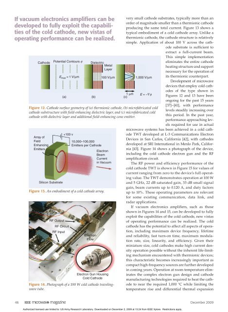
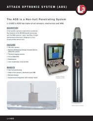
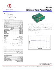
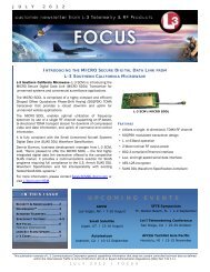
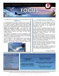
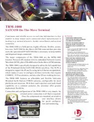
If vacuum electronics amplifiers can bedeveloped to fully exploit the capabilitiesof the cold cathode, new vistas ofoperating performance can be realized.CathodeArray ofFieldEnhancingEmittersSilicon SubstratePotential Contours φ+100 v10,000–100,000Emitters per CathodeElectronBeamCurrentin VacuumFigure 13. An embodiment of a cold cathode array.RF OutputRF CircuitRF InputElectronFlowDielectricMetalLayerE max = 1 V/μm 100 V/μm 1,000 V/μm1 μm(a) (b) (c)Electron Gun HousingCold CathodeFigure 14. Photograph of a 100 W cold cathode travelingwavetube.very small cathode substrates, typically more than anorder of magnitude smaller than a thermionic cathodeproducing the same total current. Figure 13 shows atypical embodiment of a cold cathode array. Unlike athermionic cathode, the cathode structure is relativelysimple. Application of about 100 V across the cathodesubstrate is sufficient toextract a full-current beam.This simple implementationeliminates the entire cathodeheating structure and supportnecessary for the operation ofE = –∇φFigure 12. Cathode surface geometry of (a) thermionic cathode, (b) microfabricated coldcathode substructure with field-enhancing dielectric layer, and (c) microfabricated coldcathode with dielectric layer and additional field-enhancing cone emitter.its thermionic counterpart.Development of microwavedevices that employ cold cathodesof the type shown inFigures 12 and 13 have beenongoing for the past 15 years[37]–[41], with performancelevels steadily increasing overthis period. In the past year,performance approaching levelsrequired for use in actualmicrowave systems has been achieved in a cold cathodeTWT developed at L-3 Communications ElectronDevices in San Carlos, California [42], with cathodesdeveloped at SRI International in Menlo Park, California[43]. Figure 14 shows a photograph of the device,including the cold cathode electron gun and the RFamplification circuit.The RF power and efficiency performance of thecold cathode TWT is shown in Figure 15 for values ofcurrent ranging <strong>from</strong> zero to the device’s full operatingvalue. The TWT demonstrates operation at 100 Wand 5 GHz, 22 dB saturated gain, 33 dB small signalgain, beam currents up to 0.120 A, and duty factorsup to 10%. These operating parameters are relevantfor some existing communication, data link, andradar applications.If vacuum electronics amplifiers, such as thoseshown in Figures 14 and 15, can be developed to fullyexploit the capabilities of the cold cathode, new vistasof operating performance can be realized. The coldcathode has the potential to affect all aspects of operation,including maximum device frequency, lifetimeand reliability, fast turn-on time, maximum modulationrate, size, linearity, and efficiency. Given theirminiature size, cold cathodes make high current densityoperation possible without the inherent life-limitingmechanism encountered with thermionic devices;this characteristic becomes increasingly important ascompact high-frequency sources are further developedin coming years. Operation at room temperature eliminatesthe complex electron gun design and cathodemanufacturing technologies required to heat the cathodeto near the required 1,000 °C while limiting thetemperature rise and differential thermal expansion46 December <strong>2009</strong>Authorized licensed use limited to: US Army Research Laboratory. Downloaded on December 2, <strong>2009</strong> at 13:24 <strong>from</strong> <strong>IEEE</strong> Xplore. Restrictions apply.
of surrounding gun material. Instant device turn-onis also possible with devices employing cold cathodes.Time scales for cold cathode turn-on <strong>from</strong> an off stateto fully on state are decreased by several orders of magnitude,as the thermionic cathode responds on thermaldiffusion time scales of seconds, while the cold cathoderesponds on voltage charging time scales of tens ofnanoseconds. In addition, the turn-on voltage for thesecathodes is reduced by an order of magnitude belowthat of an electrode-modulated thermionic cathode,thereby reducing modulator voltage requirements andincreasing modulation rates, both by an order of magnitude.The importance of and benefit derived <strong>from</strong>cold cathode implementation depends on the intendedapplication, though the potential of this newly developedtechnology to affect the ultimate performancelimits of all RF vacuum devices is clear.Sheet-Beam AmplifiersSheet-beam millimeter-wave amplifiers offer theprospect of considerably higher power and specificpower (output power per unit weight and volume)than can be achieved with comparable pencil-beamdevices because significantly higher current can betransported through the circuit at a given voltage.This advantage is particularly important as the frequencyof vacuum electronics amplifiers increasesto 100 GHz and beyond because the dimensions ofthe beam tunnel, as well as the slow-wave structure,scale as the wavelength λ. In a pencil-beam device, thebeam diameter must be approximately λ/10 or less.Space-charge forces and beam temperature effectsfundamentally limit the current that can be transportedin such a small diameter beam thus limitingthe power that can be generated. The power density ofthe electromagnetic field that can be supported by thebeam-wave interaction structures and couplers is alsolimited by breakdown and heating effects, imposingan additional limitation on the output power as thevolume of these structures decreases with increasingfrequency. Empirically, the output power scalesroughly as l 3 . To overcome these limitations whileretaining the many positive features of slow-wave orstanding-wave amplifiers, it is necessary to somehowincrease the beam cross-section and the beam-waveinteraction volume. Sheet beams provide a solution.An example sheet structure is shown in Figure 16.Sheet-beam devices are also attractive because theplanar topology is relatively simple to fabricate. Thisis particularly important at millimeter-wave and terahertzfrequencies, where the very small feature sizesand tolerances can be achieved by lithographic microfabricationtechniques, such as lithography, electroplating,and molding and deep reactive-ion etching.However, the successful development and implementationof sheet-beam devices also present somedifficult challenges that have so far severely limitedSheet-beam millimeter-wave amplifiersoffer the prospect of considerablyhigher power than can be achievedwith comparable pencil-beam devices.the realization of this technology. In fact, sheet beamamplifiers have been pursued for well over 50 years[44], but, generally, they have yet to be proven as apractical alternative to pencil-beam devices. Thereare a number of reasons for this arrested development.First and perhaps the most fundamental is thatthe basic advantage of a sheet beam only holds if theelectron current density can be maintained at approximatelythe same level of the corresponding pencilbeam, and this is quite difficult due to potential sheetbeam instabilities, edge effects, and nonuniformities.A high degree of uniformity of both the beam andthe RF field across the width of the sheet is necessaryOutput Power (W)12010080604020100 W120 mA5 GHz22 dB sat Gain33 dB ss Gain24% Efficiency000.000 0.025 0.050 0.075 0.100 0.125Beam Current (A)Figure 15. Measured cold cathode traveling-wave tubepower and efficiency performance data.Figure 16. Sheet beam coupled-cavity traveling wavestructure with expanded view of one cell.605040302010Circuit Efficiency (%)December <strong>2009</strong> 47Authorized licensed use limited to: US Army Research Laboratory. Downloaded on December 2, <strong>2009</strong> at 13:24 <strong>from</strong> <strong>IEEE</strong> Xplore. Restrictions apply.