Copyright © 2009 IEEE. Reprinted from Microwave Magazine - L-3 ...
Copyright © 2009 IEEE. Reprinted from Microwave Magazine - L-3 ...
Copyright © 2009 IEEE. Reprinted from Microwave Magazine - L-3 ...

You also want an ePaper? Increase the reach of your titles
YUMPU automatically turns print PDFs into web optimized ePapers that Google loves.
<strong>Copyright</strong> © <strong>2009</strong> <strong>IEEE</strong>. <strong>Reprinted</strong> <strong>from</strong> <strong>Microwave</strong> <strong>Magazine</strong>This material is posted here with permission of the <strong>IEEE</strong>. Such permission of the <strong>IEEE</strong>does not in any way imply <strong>IEEE</strong> endorsement of any of L-3 Communications ElectronDevices’ products or services. Internal or personal use of this material is permitted.However, permission to reprint/republish this material for advertising or promotionalpurposes or for creating new collective works for resale or redistribution must beobtained <strong>from</strong> the <strong>IEEE</strong> by writing to pubs-permissions@ieee.org.By choosing to view this document, you agree to all provisions of the copyright lawsprotecting it.
FOCUSEDISSUE FEATUREMost microwave engineerstrained inthe art of solid-stateelectronicshavehad little or no exposure to the basicphysics and operational principles ofmodern vacuum electronics technology.Consequently, many fail toappreciate the capability, efficiency,and reliability of this remarkableand durable technologyand fail to take advantage of itas a cost-effective, high-powersolution when makingsystem-level decisions. Thegoal of this article is to bridge part ofthis gap. It is not intended as a tutorial onthe subject; there are textbooks available for thatpurpose [1], [2]. Instead, it has two purposes: Provide thereader with an overview of the current capability of the stateof the art and provide a glimpse of the research trends of thenear future. More information and in-depth analysis can befound in [3], which contains an excellent collection of reviewarticles covering broad aspects of vacuum electronics scienceand technology.Vacuum electronics technology is both old and new;its legacy is impressive and well-known. However, recordCOURTESY OFL-3 ELECTRONTECHNOLOGIES, INC.Joe X. Qiu, Baruch Levush, John Pasour, Allen Katz,Carter M. Armstrong, David R. Whaley, Jack Tucek,Kenneth Kreischer, and David GallagherJoe X. Qiu (joe.qiu@arl.army.mil) is with the Army Research Laboratory, Adelphi, MD 20783. Baruch Levush and John Pasour are withthe Naval Research Laboratory, Washington, DC 20375. Allen Katz is a professor in the Electrical and Computer Engineering Departmentat The College of New Jersey, and is President of Linearizer Technology, Inc., Hamilton, New Jersey 08619. Carter M. Armstrong and DavidR. Whaley are with Electron Devices Division, L-3 Communications, San Carlos, California 94070. Jack Tucek, Kenneth Kreischer, and DavidGallagher are with Northrop Grumman Corporation, Rolling Meadows, Illinois 60008.Digital Object Identifier 10.1109/MMM.<strong>2009</strong>.93451738 1527-3342/09/$26.00©<strong>2009</strong> <strong>IEEE</strong>December <strong>2009</strong>Authorized licensed use limited to: US Army Research Laboratory. Downloaded on December 2, <strong>2009</strong> at 13:24 <strong>from</strong> <strong>IEEE</strong> Xplore. Restrictions apply.
Average Power (W)10 710 610 510 410 310 210 1levels of performance andreliability are now evolv ingvia modern innovations thatexploit new materials, electromagnetic structures, fabri cationtechniques, and de signs.Vacuum electronics technologyhas been and willcontinue to be the enablingtechnology for entire classesof high-power, high-frequencyamplifiers, with the mostdemanding specificationsfor use in both military andcommercial systems. Thesedemands are steadily drivingdesigners of electronicsystems into the frequency/power parameter space thatis the natural domain of vacuumelectronics technology.In addition to a wide varietyof military and commercialapplications requiring highpower at high frequency, vacuumelectronics (VE) amplifiers and oscillators are usedin scientific research areas such as high-energy particleaccelerators and plasma heating for controlled thermonuclearfusion. They are also widely used in manymedical systems, such as compact radio-frequency(RF) accelerators and, recently, in nuclear magneticresonance spectrometers for dynamic nuclear polarizationexperiments [4]. Commercial satellite communicationsystems, broadcasting, and microwave ovensfor industrial and home use are also heavily dependenton vacuum devices for reliable performance athigh power, high efficiency, and low cost. Only vacuumelectronic devices meet many of these demandingrequirements [5], [6]. Figure 1 shows the range ofpower and frequency for key applications.The figure of merit, Pf 2 , captures the ability of adevice to generate RF power, where P is the averagepower and f is the operating frequency. Figure 2 showsthe steady progress in Pf 2 achieved for various vacuumelectronics device types. For example, Pf 2 for helixtraveling-wave tubes (TWTs) has seen a three-orderof-magnitudeimprovement in the past 50 years andis poised for further growth with continued innovations,such as using brace support rods and CVD diamondsupport rods for more efficient heat removal [7].Noteworthy improvements in vacuum electronicsamplifier reliability have been realized over thepast several decades. The operational lifetimes ofthe principal types of vacuum electronic amplifiers,always substantial, are now remarkable. For example,space-based applications require service lifetimesin excess of 150,000 hours (18 years); current data for110 –1LinearAccelerators(
Most microwave engineersfail to appreciate the capability,efficiency, and reliability of vacuumelectronics technology.made possible by the advances in devices based onwide bandgap semiconductor material (GaN), as wellas more efficient power combining techniques [10],[11]. As a result, the power advantage of tube-basedamplifiers over SSPAs is no longer obvious at lowermicrowave frequencies, although they still have betterefficiency than SSPAs. In response to the challengesand market demand, the last decade has seen significantefforts by the VE industry to develop devices withAverage Power (W)10 510 410 310 210 1PPM FocusedHelix TWT<strong>Microwave</strong>PowerPPM FocusedCC TWTModules1 Solid-StateThree Terminal10 –110 –2 0.1Single Device Limits1 10 100Frequency (GHz)Figure 3. Performance domain for the different high-poweramplifier technologies: Traveling-wave tubes (TWTs)including helix and coupled-cavity types, microwave powermodules (a solid-state and TWT hybrid) and solid-statepower amplifiers. Also shown is the common developmenttrend for the different technologies: higher power andhigher frequency.P(kW)f (GHz)Δf (GHz)1,000100101TWT-PPMTWT-SolenoidKlystron-PMMMPMSSPA0.128 30 32 34 36 38 40 42 44 46f (GHz)Figure 4. The figure of merit Pf 2 (Δf/f) for selectedmillimeter-wave power amplifiers including traveling-wavetube (TWT) amplifier, millimeter-wave power module(MMPM), klystron, and solid-state power amplifier (SSPA).higher power and greater bandwidth at the millimeter-waveband. More than 1 kW of millimeter-wavepower can now be produced with high efficiency in arelatively small package [12].Common to both defense and commercial applicationsis the need for increased signal power to achievethe required signal-to-noise ratios over large transmissiondistances and large-signal bandwidth (which, inturn, calls for higher operating frequencies) to accommodatemassive volumes of data. To measure the abilityof the devices to transmit information, the figure ofmerit Pf 2 1Df@f2, where 1Df@f2 is the fractional instantaneousbandwidth of an amplifier, is plotted for a numberof amplifiers at or above 30 GHz in Figure 4. Thehigh mark of a 100 kW GHz 2 is achieved by a 35 GHzhelix TWT with a periodic permanent magnet for beamfocusing. Presently, about 1 kW GHz 2 is achieved by a35 GHz SSPA. The larger value, about 500 kW GHz 2 , forsolenoid focusing devices is because of their ability totransmit more current than devices with periodic permanentmagnet. However, solenoid magnets are bulkyand heavy and require a separate power supply andcooling. As will be discussed later, the ongoing researcheffort to use a spatially distributed beam, such as a sheetbeam, would enable the achievement of greater than500 kW GHz 2 in a smaller permanent magnet.Next, we will give a brief overview of the commontube amplifiers used in high-power transmitters. Onlythree types of devices [TWTs including helix and coupled-cavitytypes, microwave power modules (MPMs),and klystrons] will be covered, with emphasis on therecent advance in the millimeter-wave band. Referencesto other tube devices can be found in the many proceedingsof the <strong>IEEE</strong> International Vacuum ElectronicsConference, as well as in the special issues on vacuumelectronics of <strong>IEEE</strong> Transactions on Electron Devices. Thesepublications contain a significant number of papers<strong>from</strong> countries such as Russia, China, France, Japan,South Korea, Italy, and the United Kingdom.Current Status of TWTAsIn the design of high-power transmitters for airborne,space, and mobile applications, a strong emphasisis placed on minimizing the power consumption,applied voltage, size, and weight of the amplifiers. Forsuch applications, where instantaneous bandwidth isalso a requirement, helix and coupled-cavity TWTs arethe device types of choice.The main reasons for the continued reliance onvacuum electronic amplifiers such as TWTAs in spacebasedtransponders and ground terminals are TWTAs’high output power and high efficiency. The typicalavailable powers for commercial satellite communicationTWTAs and SSPAs are compared in Figure 5.The power advantage of TWTAs over SSPAs is significant,especially at the higher frequency bands. At thelower frequency bands, on the other hand, the TWTAs’40 December <strong>2009</strong>Authorized licensed use limited to: US Army Research Laboratory. Downloaded on December 2, <strong>2009</strong> at 13:24 <strong>from</strong> <strong>IEEE</strong> Xplore. Restrictions apply.
grip on power is being challenged by SSPAs. For example,at C-band, commercially available modular SSPAsare capable of producing 1.5 kW of output power, and3.0 kW by phase-combining two systems [13]. However,these SSPAs are still relatively inefficient, withefficiency at less than 20%. Compared to a linearizedTWTA (LTWTA) producing similar RF power,the above SSPA would cost US$14,000 more in annualelectricity cost [14].Collector depression is a common technique forimproving the efficiency of TWTs [1]. Using a depressedcollector, one can convert some of the kinetic energy inthe spent electron beam (i.e., after its interaction withthe slow-wave circuit) into the potential energy of thepower supplies and, therefore, increase the overall efficiencyof the device [1, ch. 14]. Additional improvementcan be achieved by employing a multistage depressedcollector (MSDC) that can better match the energydistribution of the spent beam. The total efficiency ofstate-of-the-art space TWTs with a MSDC is over 70%[15] with typical TWTA efficiency between 50–60%. Thetypical SSPA’s efficiency is about 25–30% [16].The linearity of a power amplifier is always of greatimportance. For communication applications, theTWTA has long been considered as a device with poorlinearity as compared to the SSPA. The general belief isthat a TWTA must be backed off 3–4 dB <strong>from</strong> saturationto achieve the same level of linearity as an SSPA. This isan incomplete statement. It was pointed out in [16] thatthe power consumed by a TWTA is usually less thanthat of an SSPA with only half of the rated RF power. Asa result, for two amplifiers with the same total powerconsumption, a TWTA generally has more available linearpower than an SSPA for most of the frequency band.The two amplifiers have the same linearity performancefor lower-power and lower-frequency amplifiers only.Furthermore, the linearity of a TWTA can be improvedmuch more by use of linearization than that of an SSPA.As a result, more of the TWTA’s RF power that is lostdue to output backoff is available as linear power.Predistortion linearization is a simple and effectivetechnique for improving the performance of bothSSPAs and TWTAs [17]. Its effectiveness on TWTAs ismore significant because of the slow approach to saturationand the higher nonlinearity of the TWTA. It hasbeen shown that by applying fifth-order linearization,it is possible to achieve less than 1 dB overall gain compressionat saturation so that the combined transfercurve approaches that of an ideal linear limiter [18].Consequently, the need for backoff <strong>from</strong> saturation canbe greatly reduced to take advantage of the higher efficiencynear saturation.The effect of reduced efficiency by operating significantlybelow saturation to obtain linearity can bemitigated by reoptimizing the helix circuit for reducedgain compression and phase shift. It can also be mitigatedby reoptimizing the MSDC (both the collectorOnly vacuum electronic devices meetmany of the demanding requirementsfor reliable performance.Power (W)3,0002,0001,0000C X Ku DBSFrequency Banddesign and depressed voltages) to better match thespent beam distribution at large backoff operation.This will improve the collector efficiency and, therefore,the total efficiency. L-band and S-band TWTs at200–300 W output with 25–40% efficiency and eighttonecarrier-to-intermodulation ratio levels of 270 dBchave been produced with this technique. This performanceis a significant improvement over solidstatesystems having the same fidelity and twice theefficiency of SSPA [19].Recently, a new unexplored regime of TWT operation,based on the transverse interaction betweenan electron beam and a circularly polarized circuitwas investigated [20]. It was predicted that aC-band transverse TWT could be more efficient andmore linear—12 dB smaller value for the carrier-tointermodulationratio—than a conventional longitudinalTWT with a comparable saturated power. SuchTWTAs, if implemented, could meet the demandingrequirement for high-data-rate communication.The last decade has also seen a leap in the performanceof helix TWTs. These devices have criticalapplications in high-data-rate communications,high-resolution radar, and broadband electronic warfare.For example, in [21], a record helix TWT performancehas recently been reported at C- and X-band,with 25 kW and 8 kW peak power for radar applications.Compact (around 3.5 lb) helix TWTs at Ka-band(30 GHz) with 500 W continuous wave (CW) power,and 55% efficiency and at Q-band (44 GHz), with 230W CW power and 43% efficiency [22] have been demonstratedfor communication applications. A majorcontributing factor for the millimeter-wave TWTKaTWTASSPAKPAFigure 5. Typical power of commercial satellitecommunication high-power amplifiers including travelingwavetube amplifier (TWTA), klystron power amplifier(KPA) and solid-state power amplifier (SSPA).QDecember <strong>2009</strong> 41Authorized licensed use limited to: US Army Research Laboratory. Downloaded on December 2, <strong>2009</strong> at 13:24 <strong>from</strong> <strong>IEEE</strong> Xplore. Restrictions apply.
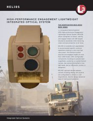
The power advantage of travelingwavetubes over solid-state poweramplifiers is significant, especiallyat the higher frequency bands.achievements is the use of a simulation-based designmethodology. This design methodology relies heavilyon the suite of recently developed codes for vacuumelectron devices [23]–[25].A coupled-cavity TWT uses a slow-wave circuitthat is mechanically and thermally more robust thana helix. A coupled-cavity structure is usually largerin size than a helix structure at the same frequency.It can, therefore, provide higher power at the samefrequency or operate at much higher frequencies thana helix TWT. One example is Communication PowerIndustries, Inc.’s Millitron coupled-cavity TWT [26]. Itis capable of producing 3 kW peak and 300 W averagepower at W-band.Current Status of <strong>Microwave</strong>and Millimeter-Wave Power ModulesThe MPM [27], [28] is an example of what RobertSymons calls appropriate technology [29]. In the caseof a low noise, high efficiency compact microwaveor millimeter-wave power amplifier, the appropriatetechnology to use is solid state for the input amplificationand vacuum electronics for the output. Thisgain partitioning between solid state and vacuumelectronics is what defines the MPM. When marriedwith a miniaturized electronic power conditioner,a high-power-density RF amplifier module results,providing 100 W and higher in the microwavebands and 50 W and higher in the millimeter-wavebands. The combined performance in size, weight,High-VoltageModuleSSA2.9-mmInputControl28-VdcInputWRD-180OutputLow-VoltageBoardTWTFigure 6. 40 W Ka-band microwave power module withcomponents/subassemblies identified. SSA: solid stateamplifier. TWT: traveling wave tube. <strong>Microwave</strong> powermodule cover has been removed.efficiency, bandwidth, and noise level is unattainableusing either constituent technology alone. Dueto its small size and high efficiency, the MPM is particularlywell-suited for use in resource-constrainedapplications, including communication (wireless),radar, and electronic warfare.A millimeter-wave power module (MMPM), as thename suggests, is simply a MPM designed to operatein the millimeter-wave frequency bands. MMPMshave been developed at both Ka- and Q-band. Aphotograph of a first-generation Ka-band MMPM isshown in Figure 6. In the unit shown, a nominal 100mW solid-state gallium arsenide (GaAs) amplifierdrives a low-voltage (about 7 kV) compact vacuumpower booster helix TWT. The MMPM provides anoutput power of 40 W <strong>from</strong> 26 to 40 GHz (with 50 W inthe 30–31 GHz communication band) in a conductioncooledpackage of 7.5 in 3 8.5 in 3 1.25 in, weighing6 lbs. The module displayed operates <strong>from</strong> 28 V dcinput power, requiring 300 W (max); however, otherprime power formats, including 270 V dc and threephase115 V ac, are possible. All high voltage is selfcontainedwithin the module.Since its initial development in the 1990s, theMPM has made significant strides in both performanceand functionality. Second-generation Ka- andQ-band MMPMs currently under development atL-3 Communications Electron Devices provide twicethe output power (100 W) at nearly double the efficiency(33%) over the first-generation designs. Theseadvances are the result of the wholesale applicationof advanced modeling and simulation in componentdesign [23], [24], as well as the steady progressionin miniature multistage TWT collector technologyand incremental improvements in power conditioningefficiency. Interestingly, although the power of thesecond-generation MPMs and MMPMs has doubled,their size and weight have not increased accordingly.The result is an increase in RF power density, 1.4 3power density (W/volume) and 1.6 3 specific powerdensity (W/mass), over first-generation performance.The addition of a miniature predistortion linearizer[30] in the MPM RF chain results in an increasein rated linear power of two and one-half times(over operation without a linearizer) with a concomitantincrease in rated efficiency by a factor oftwo. Such improvements in linear performance areimportant for digital and multicarrier communicationapplications.Future directions in MPM and MMPM developmentpoint to the continued evolution of MPM performanceand functionality. In the power-frequencyrealm, wideband dual-mode operation covering theKa- and Q-communication bands in a single MPMwith a single TWT is envisioned. While movinghigher in frequency, compact W-band MPMs providing100 W for radar and communication are seen as42 December <strong>2009</strong>Authorized licensed use limited to: US Army Research Laboratory. Downloaded on December 2, <strong>2009</strong> at 13:24 <strong>from</strong> <strong>IEEE</strong> Xplore. Restrictions apply.
enabling the exploitation of this region of the electromagneticapplication space.MPM functionality will also continue to increase.Most of this increase will come through higher levelsof integration, such as that exhibited by the MPMtransmitter (MPM-T). The MPM-T unit is a MPMassembly providing integral cooling, reverse andforward power sampling, linearization, harmonicand electromagnetic interference (EMI) filtering,serial interface control, and optional input signalup-conversion. The MPM-T, therefore, provides thesystem user a drop-in transmitter subassembly whilestill retaining all the desirable performance attributesof the MPM. A comparison of 75–100 W solidstate and MPM forced air-cooled Ka-band amplifiersshows the MPM-T to be a factor of two times smaller,lighter, and more efficient than an equivalent SSPA.Lastly, while it may come as a surprise to some, thereliability of the MPM-T assembly is expected to beon par with, if not better than, that of an SSPA. Theoutput power of some sample MPMs and MMPMs isshown in Figure 7.Current Status of Klystron AmplifiersKlystrons operate <strong>from</strong> UHF to millimeter-wave frequencies.They possess high gain, dynamic range,power, efficiency, and low noise, albeit with relativelynarrower bandwidths compared to TWTAs.Among the many applications for klystrons is theirlong use as the workhorse for high-power transmittersin terrestrial broadcast and satellite communications.Continued technical improvementshave further reaffirmed their dominance. In [31], byincorporating MSDC, the saturation efficiency for a2.4 kW klystron designed for direct broadcast satellite(DBS) band was raised <strong>from</strong> 24% to 40%. This im -provement can result in savings of over US$10,000in energy costs per year. This MSDC technology hasled Communications & Power Industries's (CPI’s)GEN IV klystron to capture 95% of the satellite communicationsuplink klystron power amplifier (KPA)market [32]. The typical available power for commercialsatellite communications klystron amplifiersis also shown in Figure 5.For many applications, a klystron is constrained byhigh voltage, limited bandwidth, and declining powerat high frequency. Two noteworthy technologies havebeen developed to address these issues: the extendedinteractionklystron (EIK) and the multiple-beam klystron(MBK).In the EIK, one or more of the klystron cavitiesare replaced by structures containing more thanone interaction gap. Compared to conventional klystrons,EIKs have a wider bandwidth and a higherpower level because of the distributed interaction.The most interesting development in the EIKhas been at the millimeter-wave frequencies [33].Future directions in power moduledevelopment point to the continuedevolution of microwave power moduleperformance and functionality.Power (W)2502001501005001.5 Octave0 10 20 30 40 50 60Frequency (GHz)Figure 7. Average output power of sample microwavepower modules (MPMs). The diamonds are MPMs withless than 0.5 octave bandwidth; the squares are MPMs withone octave bandwith; the triangles are MPMs with greaterthan 1.5 octave bandwidth.EIKs are available at frequencies <strong>from</strong> Ka-band toG-band. For example, an EIK is capable of deliveringan average power of 400 W at 95 GHz and 9 W (CW)at 218 GHz [34].MBKs offer the advantages of reduced beam voltage,reduced size and weight, and increased bandwidthwhen compared with single-beam klystrons.Multiple-beam devices have been developed extensivelyin Russia [35]. The highest level in compactnessmay well have been achieved by ISTOK (Russia),which developed a Ku-band MBK capable of delivering0.4 kW of peak power (133 W average) weighingonly 400 g, including the magnet.Advances in Wideband TWTA LinearizationDuring the past five years, there has been great progressin the linearization of TWTAs. Linearization isstill primarily by means of predistortion because ofthe wider bandwidth and higher efficiencies achievableby this form of linearization. Both analog anddigital (digital-signal-processing based) linearizationare now being applied to TWTAs. Digital linearizationoffers the advantage of near ideal transfer responsecorrection. A two-tone carrier-to-intermodulation ratioof greater than 50 dB can be achieved with a TWTA at3 dB output power backoff <strong>from</strong> saturation.The major constraint of digital-based linearizationis bandwidth. Although it is now possible to digitallyprocess signals over greater than 1 GHz of bandwidth,December <strong>2009</strong> 43Authorized licensed use limited to: US Army Research Laboratory. Downloaded on December 2, <strong>2009</strong> at 13:24 <strong>from</strong> <strong>IEEE</strong> Xplore. Restrictions apply.
180°HybridNLGPPLinearizerNLG180°Hybrid180°HybridPAPP PowerAmplifierPA180°HybridFigure 8. A push-pull (PP) configuration may be used to minimize both linearizer andtraveling-wave tube amplifier even order distortion. NLG: nonlinear generator.C/l (dBc)4035302520151052LTWTA 10 GHzTWTALTWTA 18 GHz3 4 5 6 7 8 9 10OPBO (dB)Figure 9. Wideband linearized traveling-wavetube amplifier (LTWTA) performance. Carrier-tointermodulation(C/I) ratio versus output power backoff(OPBO) <strong>from</strong> saturation.C/I (dB)MPM Linearity @ C, X, Ku, and DBS504540353025L-MPMKuC.XK20C, XMPMKu, K15102 3 4 5 6 7 8 9 10OPBO (dB)been achieved [36]. For amplifiersof an octave or greaterbandwidth, both even- andodd-order distortion productsand both intermodulation andharmonic distortion are present.A linearizer must correctboth to achieve linear performance.Even order distortioncan be minimized by the useof a push-pull structure. Oneapproach is to use push-pullTWTs to minimize amplifiereven-order distortion. Sincethe nonlinear generators usedin the linearizer to correct odd-order intermodulationdistortion also produce some even-order distortionthat can contribute to overall power amplifier distortion,a push-pull linearizer architecture must also beused. This design approach is illustrated in Figure8, which shows both a push-pull linearizer and thepush-pull PA. If more suppression is required, aneven-order nonlinear generator can be used to supplementthe odd-order nonlinearity. Figure 9 shows measuredLTWTA data taken over a 10–18 GHz range.In many wideband high-power amplifier applications,performance is not required across the fullfrequency range but only at specific bands. Forsuch applications, multiband linearizers may providebetter performance than a single widebandlinearizer. Dual- and triband linearizers have beendeveloped and are in production for C-, X-, and Kuband.This approach uses two or three independentpredistortor modules that can be switched betweencommon input and output amplifiers and attenuators.Using this approach, each predistorter can bealigned for optimum performance in a particularfrequency band. The carrier-to-intermodulationratio performance achieved by an experimentalquad-band LTWTA is shown in Figure 10.In general, with TWTAs, the narrower the bandwidth,the higher the improvement that can beobtained by linearization, but substantial improvementover large continuous bandwidths of more thanan octave can be achieved.Figure 10. Carrier-to-intermodulation (C/I) ratioof a quad band linearized microwave power module(L-MMPM) versus output power backoff (OPBO)<strong>from</strong> saturation.practical bandwidths are presently 100 MHz or lessdue to limitations relating to the complexity, cost, andpower consumption of available digital components.There has been significant progress in extendingthe bandwidth of analog linearization. It was not verylong ago that a 20% bandwidth was considered wideband.Today, multioctave, multi-GHz bandwidths haveFuture Trends in VacuumElectronics ResearchNew applications, such as high-data-rate communication,high-resolution radar, and active imaging inthe millimeter-wave and submillimeter-wave bands,demand the availability of compact higher-powersources at these frequencies and will be the drivingforce for vacuum electronics research in the near future.The two current Defense Advanced Research ProjectsAgency (DARPA) programs developing amplifier technologiesat these frequencies are HiFIVE and Terahertz44 December <strong>2009</strong>Authorized licensed use limited to: US Army Research Laboratory. Downloaded on December 2, <strong>2009</strong> at 13:24 <strong>from</strong> <strong>IEEE</strong> Xplore. Restrictions apply.
Electronics. HiFIVE is developing amplifiers at 220 GHz,and Terahertz Electronics is developing them at 670,850, and 1030 GHz. They both include vacuum electronicstechnologies. The emer ging requirements willcontinue to push the vacuum electronics field to newlevels of performance through advances in areas suchas new physics-based advanced modeling and simulationtools, innovative cathodes, and new fabricationtechniques. Spatially distributed electron beams suchas multiple beams and sheet-beam topologies supportedby microfabrication and refinements in materials,magnetics, and electron sources, will contributeto growth opportunities. Advances in power supplytechnology may well be an important next step in sizereduction. Examples of these research efforts are givenin the following sections.Cold Cathodes for VacuumElectronics AmplifiersThe cathode lies at the heart of every vacuum electronicsRF amplifier, powering the energy-exchange circuitryfor conversion of electron kinetic energy to energy of apropagating electromagnetic wave. The cathode’s solepurpose is to create a high- energy electron beam thatstreams through the vacuum in relative proximity to thedevice’s RF circuit. Current technology employs almostexclusively thermionic cathodes—i.e., metallic compositesthat are heated by various means to near 1,000 °C. Atsuch temperatures, electrons that are normally bound tothe cathode’s metallic lattice can be extracted <strong>from</strong> thecathode surface if their thermal energies exceed the cathode’ssurface vacuum potential barrier. This method ofcreating free-streaming electron beams in a vacuum hasbeen successively employed for more than 60 years.Quantum mechanics, however, holds the promiseof fundamentally altering the method used to createstreaming electron beams in vacuums—one that willenable revolutionary performance gains for the devicesthat employ it. These cold cathodes do not requirehigh thermal electron energies for beam emission, butinstead rely on quantum mechanical tunneling thoughthe vacuum potential barrier, a barrier distorted by thecreation of high cathode surface electric fields. Figure 11depicts the potential energy diagram for electrons at thesurfaces of a thermionic cathode and a cold cathode,both at room temperature. In the case of the thermioniccathode, without additional energy q e Dw, the electronsare bound to the cathode surface and cannot escape intothe vacuum. The additional energy required must come<strong>from</strong> direct heating of the cathode via external means.In the case of the cold cathode, no additional thermalenergy is available. Instead, the shape of thevacuum barrier is distorted via application of a highelectric field to the cathode surface. The barrier isnot reduced to zero, however, and the cathode relieson quantum mechanical tunneling through the barrier,which allows for transit of electrons throughMultiple-beam klystrons offerthe advantages of reduced beamvoltage, reduced size and weight,and increased bandwidth.the forbidden zone with a nonzero probability. If thesurface electric field and vacuum barrier distortionbecome high enough, then the tunneling probabilityincreases to levels that allow sufficient vacuum currentto be extracted.To create the necessary high cathode surfacefields, new methods of cathode fabrication havebeen developed that replace the metal composites ofthe thermionic cathode with a microfabricated siliconsubstrate upon which are formed several electricfield-enhancing features. Figure 12 comparesthe surface geometry and electric field values of(a) a thermionic cathode, (b) a microfabricated coldcathode substructure with field-enhancing dielectriclayer, and (c) a microfabricated cold cathode witha field-enhancing dielectric layer and an additionalfield-enhancing cone emitter. The dielectric layerincreases the electric field over that of a thermioniccathode by about 100 times, and the cone emittersadd an additional factor of 10–100 times at the apexof the cone, creating electric fields that ultimatelyexceed the threshold for room temperature electronemission into the vacuum.The cone emitters of Figure 12(c) have micronsizedfeatures, and, typically, each produce 1–10 mAof vacuum current. The small feature size and use ofmicrofabrication techniques allow for large arraysof such emitters 110 4 210 5 2 to be manufactured ontoPotential EnergyΔφ0CathodeConductionBandΔφ0Thermionic CathodeElectronWave FunctionVacuumZero Beam EmissionWithout ExternalHeatingCold CathodeVacuumCathodeElectronConductionTunneling andBandBeam Creation25 °CDistanceFigure 11. Energy diagram for a thermionic cathode anda cold cathode. The high surface electric field for the coldcathode distorts the potential barrier and allows tunneling.December <strong>2009</strong> 45Authorized licensed use limited to: US Army Research Laboratory. Downloaded on December 2, <strong>2009</strong> at 13:24 <strong>from</strong> <strong>IEEE</strong> Xplore. Restrictions apply.
If vacuum electronics amplifiers can bedeveloped to fully exploit the capabilitiesof the cold cathode, new vistas ofoperating performance can be realized.CathodeArray ofFieldEnhancingEmittersSilicon SubstratePotential Contours φ+100 v10,000–100,000Emitters per CathodeElectronBeamCurrentin VacuumFigure 13. An embodiment of a cold cathode array.RF OutputRF CircuitRF InputElectronFlowDielectricMetalLayerE max = 1 V/μm 100 V/μm 1,000 V/μm1 μm(a) (b) (c)Electron Gun HousingCold CathodeFigure 14. Photograph of a 100 W cold cathode travelingwavetube.very small cathode substrates, typically more than anorder of magnitude smaller than a thermionic cathodeproducing the same total current. Figure 13 shows atypical embodiment of a cold cathode array. Unlike athermionic cathode, the cathode structure is relativelysimple. Application of about 100 V across the cathodesubstrate is sufficient toextract a full-current beam.This simple implementationeliminates the entire cathodeheating structure and supportnecessary for the operation ofE = –∇φFigure 12. Cathode surface geometry of (a) thermionic cathode, (b) microfabricated coldcathode substructure with field-enhancing dielectric layer, and (c) microfabricated coldcathode with dielectric layer and additional field-enhancing cone emitter.its thermionic counterpart.Development of microwavedevices that employ cold cathodesof the type shown inFigures 12 and 13 have beenongoing for the past 15 years[37]–[41], with performancelevels steadily increasing overthis period. In the past year,performance approaching levelsrequired for use in actualmicrowave systems has been achieved in a cold cathodeTWT developed at L-3 Communications ElectronDevices in San Carlos, California [42], with cathodesdeveloped at SRI International in Menlo Park, California[43]. Figure 14 shows a photograph of the device,including the cold cathode electron gun and the RFamplification circuit.The RF power and efficiency performance of thecold cathode TWT is shown in Figure 15 for values ofcurrent ranging <strong>from</strong> zero to the device’s full operatingvalue. The TWT demonstrates operation at 100 Wand 5 GHz, 22 dB saturated gain, 33 dB small signalgain, beam currents up to 0.120 A, and duty factorsup to 10%. These operating parameters are relevantfor some existing communication, data link, andradar applications.If vacuum electronics amplifiers, such as thoseshown in Figures 14 and 15, can be developed to fullyexploit the capabilities of the cold cathode, new vistasof operating performance can be realized. The coldcathode has the potential to affect all aspects of operation,including maximum device frequency, lifetimeand reliability, fast turn-on time, maximum modulationrate, size, linearity, and efficiency. Given theirminiature size, cold cathodes make high current densityoperation possible without the inherent life-limitingmechanism encountered with thermionic devices;this characteristic becomes increasingly important ascompact high-frequency sources are further developedin coming years. Operation at room temperature eliminatesthe complex electron gun design and cathodemanufacturing technologies required to heat the cathodeto near the required 1,000 °C while limiting thetemperature rise and differential thermal expansion46 December <strong>2009</strong>Authorized licensed use limited to: US Army Research Laboratory. Downloaded on December 2, <strong>2009</strong> at 13:24 <strong>from</strong> <strong>IEEE</strong> Xplore. Restrictions apply.
of surrounding gun material. Instant device turn-onis also possible with devices employing cold cathodes.Time scales for cold cathode turn-on <strong>from</strong> an off stateto fully on state are decreased by several orders of magnitude,as the thermionic cathode responds on thermaldiffusion time scales of seconds, while the cold cathoderesponds on voltage charging time scales of tens ofnanoseconds. In addition, the turn-on voltage for thesecathodes is reduced by an order of magnitude belowthat of an electrode-modulated thermionic cathode,thereby reducing modulator voltage requirements andincreasing modulation rates, both by an order of magnitude.The importance of and benefit derived <strong>from</strong>cold cathode implementation depends on the intendedapplication, though the potential of this newly developedtechnology to affect the ultimate performancelimits of all RF vacuum devices is clear.Sheet-Beam AmplifiersSheet-beam millimeter-wave amplifiers offer theprospect of considerably higher power and specificpower (output power per unit weight and volume)than can be achieved with comparable pencil-beamdevices because significantly higher current can betransported through the circuit at a given voltage.This advantage is particularly important as the frequencyof vacuum electronics amplifiers increasesto 100 GHz and beyond because the dimensions ofthe beam tunnel, as well as the slow-wave structure,scale as the wavelength λ. In a pencil-beam device, thebeam diameter must be approximately λ/10 or less.Space-charge forces and beam temperature effectsfundamentally limit the current that can be transportedin such a small diameter beam thus limitingthe power that can be generated. The power density ofthe electromagnetic field that can be supported by thebeam-wave interaction structures and couplers is alsolimited by breakdown and heating effects, imposingan additional limitation on the output power as thevolume of these structures decreases with increasingfrequency. Empirically, the output power scalesroughly as l 3 . To overcome these limitations whileretaining the many positive features of slow-wave orstanding-wave amplifiers, it is necessary to somehowincrease the beam cross-section and the beam-waveinteraction volume. Sheet beams provide a solution.An example sheet structure is shown in Figure 16.Sheet-beam devices are also attractive because theplanar topology is relatively simple to fabricate. Thisis particularly important at millimeter-wave and terahertzfrequencies, where the very small feature sizesand tolerances can be achieved by lithographic microfabricationtechniques, such as lithography, electroplating,and molding and deep reactive-ion etching.However, the successful development and implementationof sheet-beam devices also present somedifficult challenges that have so far severely limitedSheet-beam millimeter-wave amplifiersoffer the prospect of considerablyhigher power than can be achievedwith comparable pencil-beam devices.the realization of this technology. In fact, sheet beamamplifiers have been pursued for well over 50 years[44], but, generally, they have yet to be proven as apractical alternative to pencil-beam devices. Thereare a number of reasons for this arrested development.First and perhaps the most fundamental is thatthe basic advantage of a sheet beam only holds if theelectron current density can be maintained at approximatelythe same level of the corresponding pencilbeam, and this is quite difficult due to potential sheetbeam instabilities, edge effects, and nonuniformities.A high degree of uniformity of both the beam andthe RF field across the width of the sheet is necessaryOutput Power (W)12010080604020100 W120 mA5 GHz22 dB sat Gain33 dB ss Gain24% Efficiency000.000 0.025 0.050 0.075 0.100 0.125Beam Current (A)Figure 15. Measured cold cathode traveling-wave tubepower and efficiency performance data.Figure 16. Sheet beam coupled-cavity traveling wavestructure with expanded view of one cell.605040302010Circuit Efficiency (%)December <strong>2009</strong> 47Authorized licensed use limited to: US Army Research Laboratory. Downloaded on December 2, <strong>2009</strong> at 13:24 <strong>from</strong> <strong>IEEE</strong> Xplore. Restrictions apply.
for strong and efficient beam-wave interaction. Also,sheet-beam interaction circuits are intrinsically overmoded,and fabrication errors or slight misalignmentsof the beam relative to the circuit can cause undesiredmodes to be excited. Thus, two major obstacles thatmust be overcome to achieve the full potential of sheetbeamamplifiers are 1) the formation and transport ofa sufficiently high perveance and uniform beam and2) the design and fabrication of suitable interactioncircuits, both of which must be executed with a highdegree of precision.Most sheet beam research has focused on magnetictransport, utilizing periodic permanent magnets[45], [46]. Such a configuration is relativelylight and compact, and stable beam transport can beachieved over a relatively long length. The key disadvantageof periodic permanent magnet focusing isthat it imposes a minimum beam voltage for stabilitythat is often far higher than desirable <strong>from</strong> systemsconsiderations. The alternative magnetic focusingscheme, employing a uniform or solenoidal field,can provide significantly higher field strength (andhence stronger focusing) <strong>from</strong> available permanentmagnets than periodic permanent magnet focusing,but it has usually been avoided because of potentialinstabilities [47].To determine the optimum transport technique for asheet beam, these stability considerations must be combinedwith the beam envelope equation, which determinesthe magnetic field strength required to balancethe outward space-charge and beam temperature forceson the beam. For relatively low-voltage (,20–25 kV)sheet beam devices, a solenoidal field can transport significantlyhigher current densities, thereby achievinghigher output power [48]. The price that must be paidis a somewhat heavier and larger magnet assembly.Whichever approach is used, the transport field mustbe carefully matched to the electron gun.25 cmPermanent GunMagnets (20 kv, 3.5 A)CollectorBeamTunnelPolePiecesEIK Circuit withInput/OutputGuidesInteractionCavitiesFigure 17. Layout of NRL’s 94 GHz sheet-beam extendedinteration klystron (EIK). The permanent magnet producesa uniform 8.5-kG field over the interaction volume.Most sheet-beam circuit configurations that havebeen considered for millimeter-wave amplifiers areeither like EIK, consisting of a number of discrete cavitystructures, or traveling-wave types, with a suitablestructure to slow the wave phase velocity to match theelectron velocity. While these configurations are generallyanalogous to corresponding well-developed pencil-beamstructures, their design and optimization arecomplicated and quite challenging. Unlike the beamtunnel in pencil-beam devices, which is below cut-offfor the operating frequency so that adjacent circuit elementsare isolated, a sheet beam tunnel is wide enoughto propagate the fundamental transverse electric (TE)mode, which can easily be excited and lead to oscillationand/or beam disruption if the midplane symmetryof the tunnel, circuit, and beam is destroyed by misalignment,fabrication errors, etc. Also, as the aspectratio of a sheet beam device increases, it becomes moredifficult to ensure uniformity and proper phasing ofthe beam and the mode field across the entire widthof the device.Recent progress in devising such sheet beamstructures, largely facilitated by more powerful computercodes and computing resources, is promising.These codes are enabling much more realistic designsto be evaluated and, with their optimization routinesto fine-tune parameters, make first-pass fabricationsuccess a reality. As an example, such simulationspredict that a 94-GHz, 20-kV, 3.5-A sheet-beam EIK,which has an interaction circuit ,1.5 cm long, cangenerate a peak output power .10 kW. This is at leasta factor of five larger than a pencil-beam device atthis frequency and operating voltage. A device basedon this simulation is being fabricated (Figure 17), andefforts are underway to scale such devices into theterahertz regime.Compact, High-Power Terahertz SourcesSince demonstrating the first operation of a vacuumelectronic terahertz source based on microfabricatedfolded-waveguide (FWG) technology [49], NorthropGrumman has continued the development of compact,high-power THz sources in support of several DARPATHz initiatives. Similar to classical vacuum electronicdevices, these THz sources consist of a thermionic electronsource, a slow-wave interaction circuit to amplifythe RF wave, and a depressed collector to recoverenergy <strong>from</strong> the spent beam for efficient source operation.A 10 kG Nd-Fe-B permanent magnet solenoid isused to magnetically confine the electron beam as itpasses through the slow-wave structure. Vacuum electronicsdevices based on FWG regenerative oscillatorcircuits have been successfully fabricated and operatedbetween 0.600–0.675 THz with RF power levelsover 50 mW at duty cycles up to 3% [50]. This is significantlyhigher than the power capability of existingsources operating at these frequencies.48 December <strong>2009</strong>Authorized licensed use limited to: US Army Research Laboratory. Downloaded on December 2, <strong>2009</strong> at 13:24 <strong>from</strong> <strong>IEEE</strong> Xplore. Restrictions apply.
A FWG slow-wave circuit is a serpentine waveguide,folded back upon itself multiple times, with abeam tunnel through the center of the structure. TheFWG is designed such that the axial velocity of theRF wave in the waveguide can be made to matchthe group velocity of the electrons travelling downthe beam tunnel. In order to achieve efficient couplingof the RF wave to the electron beam at THz frequencies,the cross-sectional dimensions of the FWG are onthe order of tens of microns by hundreds of microns,which must not vary over the entire circuit length ofseveral centimeters.Another requirement is smooth walls to minimizethe waveguide attenuation due to the shallowskin depth at THz frequencies. Realization of circuitsmeeting these requirements has only been enabledby the use of modern microfabrication techniques,like deep reactive-ion etching of silicon coupled withcopper sputter deposition and electroplating. The planarnature of the FWG circuit is naturally amenableto these planar microfabrication processes, enablingbatch processing of multiple circuits on a single wafer.Additionally, FWG circuits do not rely on fragile structuressuch as gratings to achieve amplification, and,therefore, they are structurally more robust. Theyare fabricated <strong>from</strong> a solid block for better thermalmanagement. Finally, cofabricated tapers at each endof the serpentine waveguide provide a natural andeffective way for coupling power into and out of thecircuit. The FWGs used in the terahertz sources (Figure18) were fabricated in halves (mirror-images) bya two-level silicon deep reactive-ion etching process:One step to create the FWG itself and a second step tocreate the beam tunnel through the FWG structure.Each half was then metalized via copper electroplating,aligned, and bonded together, forming the completedFWG circuit.In addition to the careful design and accuratefabrication of the FWG interaction circuit, the electrostaticgun design, electron beam transport magnetics,and the collector design are crucial in orderto achieve compact, high-power devices that operatewith minimal beam intercept and high device efficiency.Focus and transport of a 4 mA beam throughthe 60 360 mm 2 beam tunnel (60 mm—roughly thediameter of an average human hair) is a technicalchallenge as mechanical offsets, edge-emitted electrons<strong>from</strong> the cathode, and localized transversemagnetic fields on the order of a few tens of Gauss(less than 1% of the overall axial field) can force thebeam off axis, leading to significant beam intercept.Precision fabrication of the electron gun assembly,accurate mechanical alignment of the gun with thebeam tunnel in the FWG circuit, and minimizationof the transverse magnetic fields have lead to a beamtransmission of 78% for a 4.8 mA beam at 10 kV in arecent prototype. Lastly, the design of a single-stage,graphite lens collector was optimized to recover92.4% of the energy <strong>from</strong> the spent electron beam.The THz source prior to final assembly is shown inFigure 19.After assembly and exhaust, the vacuum electronicsFWG THz source is mounted on the test stand in thebore of the permanent magnet solenoid. Beam focusand transmission are controlled by the alignment ofthe magnet, which is adjusted, relative to the source,with two three-axis translation stages. A cylindricalcopper waveguide serves as an overmoded, externaloutput waveguide to transmit RF output power toFigure 18. Folded-waveguide circuit half fabricated bydeep reactive-ion etching process.Figure 19. The terahertz source prior to final assembly.Frequency (GHz)700680660640620TheoryExperiment6009,000 9,250 9,500 9,750 10,000Beam Voltage (V)Figure 20. Terahertz source operating frequencies.December <strong>2009</strong> 49Authorized licensed use limited to: US Army Research Laboratory. Downloaded on December 2, <strong>2009</strong> at 13:24 <strong>from</strong> <strong>IEEE</strong> Xplore. Restrictions apply.
At millimeter-wave bands, theperformance of vacuum electronicsdevices is not likely to be matchedby solid-state power amplifiers in thenear future.the THz detector. A 2 L/s ion pump maintains thevacuum, and nitrogen gas flows through the magnetbore to stabilize the temperature of the source duringtesting.Table 1 summarizes the operating characteristicsfor a recent THz source prototype. This source operatedat 0.656 THz, 9.9 kV, and 46% beam transmission.Measured power at the output window was 52 mW. Inthe oscillator, the estimated single pass gain is around15 dB, which is equal to the total loss of the return path.The size of the compact device is driven mainly by thesize of the cylindrical magnet with a diameter of 3.4 inand a length of 4.9 in.The oscillation frequency is observed to step-tuneas the beam voltage is varied <strong>from</strong> 9.6 kV to greaterthan 10 kV, as shown in Figure 20. It is believed thatthese steps are characteristic of the regenerative feedbackFWG circuit in the source. In general, there wasmegahertz stability <strong>from</strong> pulse to pulse. The measuredline-width was less than 30 MHz due, in part,to fluctuations of the beam current and voltage duringthe pulse. Measurable power was observed between607–675 GHz.Work is presently underway to extend FWG devicetechnology to develop compact, high-power vacuumelectronic amplifiers and fully integrated powerTABLE 1. THz source operation parameters.ParameterPower at windowFrequencySingle pass gainCathode voltagePulse lengthRepetition rateValue52 mW0.656 THz,15 dB9.9 kV0.05–1.0 ms#30 HzDuty cycle, maximum 3 %Axial fieldEmission currentCollector current10 kG4.6 mA2.1 mABeam transmission 46 %Interaction efficiency 0.4 %Source efficiency 0.2 %modules (a solid-state driver amplifier together with aFWG amplifier) to operate <strong>from</strong> 0.2 THz to over 1 THz.ConclusionVacuum electronics amplifiers continue to play animportant role in high-power transmitter applications.At microwave frequencies, recent advances inwide bandgap semiconductor devices such as GaNand power combining techniques are enabling SSPAsto challenge the power advantage of vacuum electronicsamplifiers, but vacuum electronics devices stillhold the efficiency edge even at these frequencies. Atmillimeter-wave bands, the performance of vacuumelectronics devices, both in terms of power bandwidthproduct and efficiency, is not likely to be matched bySSPAs in the near future. The use of linearization furtherenhances the efficiency edge of vacuum electronicsamplifiers. The development of technology at theupper millimeter-wave and submillimeter-wave areenabled by cold cathode technologies and microfabricationtechniques.References[1] A. S. Gilmour, Jr., Principles of Traveling Wave Tubes. Boston: ArtechHouse, 1994.[2] A. S. Gilmour, Jr., <strong>Microwave</strong> Tubes. Boston: Artech House, 1986.[3] R. J. Barker, J. H. Booske, N. C. Luhmann, Jr., and G. S. Nusinovich,Eds., Modern <strong>Microwave</strong> and Millimeter-Wave Power Electronics. Piscataway,NJ: <strong>IEEE</strong> Press, 2005.[4] V. S. Bajaj, M. K. Hornstein, K. E. Kreischer, J. R. Sirigiri, P. P.Woskov, M. L. Mak-Jurkauskas, J. Herzfeld, R. J. Temkin, and R.G. Griffin, “250 GHz CW gyrotron oscillator for dynamic nuclearpolarization in biological solid state NMR,” J. Magn. Reson., vol.189, no. 2, pp. 251–279, Dec. 2007.[5] R. K. Parker, R. H. Abrams, Jr., B. G. Danly, and B. Levush, “Vacuumelectronics,” <strong>IEEE</strong> Trans. Microw. Theory Tech., vol. 50, no. 3, pp.835–845, Mar. 2002.[6] R. H. Abrams, Jr., B. Levush, A. A. Mondelli, and R. K. Parker,“Vacuum electronics for the 21st century,” <strong>IEEE</strong> Microw. Mag., vol.2, no. 3, pp. 61–72, Sept. 2001.[7] A. V. Galdetskiy, “Helix slow-wave structure with diamond supportfor power TWTs,” in Proc. 6th Int. Vacuum Electronics Conf.,Noordwijk, The Netherlands, Apr. 2005, pp. 471–472.[8] J. M. Weekley and B. J. Mangus, “TWTA versus SSPA: A comparisonof on-orbit reliability data,” <strong>IEEE</strong> Trans. Electron Devices, vol. 52,no. 5, pp. 650–652, May 2005.[9] “Solid-state power invades the tube realm,” in Proc. <strong>IEEE</strong> MTT-SInt. <strong>Microwave</strong> Symp. Workshop, Honolulu, HI, June 2007.[10] H. Shigematsu, Y. Inoue, A. Akasegawa, M. Yamada, S. Masuda,Y. Kamada, A. Yamada, M. Kanamura, T. Ohki, K. Makiyama, N.Okamoto, K. Imanishi, T. Kikkawa, K. Joshin, and N. Hara, “C-band340-W and X-band 100-W GaN power amplifiers with over 50-%PAE,” in Proc. Int. <strong>Microwave</strong> Symp., Boston, MA, June <strong>2009</strong>, TH3A-1.[11] H. Sumi, H. Takahashi, T. Soejima, and R. Mochizuki, “Ku-band,120-W power amplifier using gallium nitride FETs,” in <strong>IEEE</strong> MTT-SInt. <strong>Microwave</strong> Symp. Dig., Boston, MA, June <strong>2009</strong>, TH4A-3.[12] “Millimeter-wave power amplifier technology: Power, linearityand efficiency,” in Proc. <strong>IEEE</strong> MTT-S Int. <strong>Microwave</strong> Symp. Workshop,Atlanta, GA, June 2008.[13] General Dynamics SATCOM Technologies. [Online]. Available:http://www.gdsatcom.com/electronics.php#solid50 December <strong>2009</strong>Authorized licensed use limited to: US Army Research Laboratory. Downloaded on December 2, <strong>2009</strong> at 13:24 <strong>from</strong> <strong>IEEE</strong> Xplore. Restrictions apply.