Copyright © 2009 IEEE. Reprinted from Microwave Magazine - L-3 ...
Copyright © 2009 IEEE. Reprinted from Microwave Magazine - L-3 ...
Copyright © 2009 IEEE. Reprinted from Microwave Magazine - L-3 ...

Create successful ePaper yourself
Turn your PDF publications into a flip-book with our unique Google optimized e-Paper software.
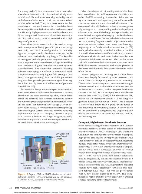
for strong and efficient beam-wave interaction. Also,sheet-beam interaction circuits are intrinsically overmoded,and fabrication errors or slight misalignmentsof the beam relative to the circuit can cause undesiredmodes to be excited. Thus, two major obstacles thatmust be overcome to achieve the full potential of sheetbeamamplifiers are 1) the formation and transport ofa sufficiently high perveance and uniform beam and2) the design and fabrication of suitable interactioncircuits, both of which must be executed with a highdegree of precision.Most sheet beam research has focused on magnetictransport, utilizing periodic permanent magnets[45], [46]. Such a configuration is relativelylight and compact, and stable beam transport can beachieved over a relatively long length. The key disadvantageof periodic permanent magnet focusing isthat it imposes a minimum beam voltage for stabilitythat is often far higher than desirable <strong>from</strong> systemsconsiderations. The alternative magnetic focusingscheme, employing a uniform or solenoidal field,can provide significantly higher field strength (andhence stronger focusing) <strong>from</strong> available permanentmagnets than periodic permanent magnet focusing,but it has usually been avoided because of potentialinstabilities [47].To determine the optimum transport technique for asheet beam, these stability considerations must be combinedwith the beam envelope equation, which determinesthe magnetic field strength required to balancethe outward space-charge and beam temperature forceson the beam. For relatively low-voltage (,20–25 kV)sheet beam devices, a solenoidal field can transport significantlyhigher current densities, thereby achievinghigher output power [48]. The price that must be paidis a somewhat heavier and larger magnet assembly.Whichever approach is used, the transport field mustbe carefully matched to the electron gun.25 cmPermanent GunMagnets (20 kv, 3.5 A)CollectorBeamTunnelPolePiecesEIK Circuit withInput/OutputGuidesInteractionCavitiesFigure 17. Layout of NRL’s 94 GHz sheet-beam extendedinteration klystron (EIK). The permanent magnet producesa uniform 8.5-kG field over the interaction volume.Most sheet-beam circuit configurations that havebeen considered for millimeter-wave amplifiers areeither like EIK, consisting of a number of discrete cavitystructures, or traveling-wave types, with a suitablestructure to slow the wave phase velocity to match theelectron velocity. While these configurations are generallyanalogous to corresponding well-developed pencil-beamstructures, their design and optimization arecomplicated and quite challenging. Unlike the beamtunnel in pencil-beam devices, which is below cut-offfor the operating frequency so that adjacent circuit elementsare isolated, a sheet beam tunnel is wide enoughto propagate the fundamental transverse electric (TE)mode, which can easily be excited and lead to oscillationand/or beam disruption if the midplane symmetryof the tunnel, circuit, and beam is destroyed by misalignment,fabrication errors, etc. Also, as the aspectratio of a sheet beam device increases, it becomes moredifficult to ensure uniformity and proper phasing ofthe beam and the mode field across the entire widthof the device.Recent progress in devising such sheet beamstructures, largely facilitated by more powerful computercodes and computing resources, is promising.These codes are enabling much more realistic designsto be evaluated and, with their optimization routinesto fine-tune parameters, make first-pass fabricationsuccess a reality. As an example, such simulationspredict that a 94-GHz, 20-kV, 3.5-A sheet-beam EIK,which has an interaction circuit ,1.5 cm long, cangenerate a peak output power .10 kW. This is at leasta factor of five larger than a pencil-beam device atthis frequency and operating voltage. A device basedon this simulation is being fabricated (Figure 17), andefforts are underway to scale such devices into theterahertz regime.Compact, High-Power Terahertz SourcesSince demonstrating the first operation of a vacuumelectronic terahertz source based on microfabricatedfolded-waveguide (FWG) technology [49], NorthropGrumman has continued the development of compact,high-power THz sources in support of several DARPATHz initiatives. Similar to classical vacuum electronicdevices, these THz sources consist of a thermionic electronsource, a slow-wave interaction circuit to amplifythe RF wave, and a depressed collector to recoverenergy <strong>from</strong> the spent beam for efficient source operation.A 10 kG Nd-Fe-B permanent magnet solenoid isused to magnetically confine the electron beam as itpasses through the slow-wave structure. Vacuum electronicsdevices based on FWG regenerative oscillatorcircuits have been successfully fabricated and operatedbetween 0.600–0.675 THz with RF power levelsover 50 mW at duty cycles up to 3% [50]. This is significantlyhigher than the power capability of existingsources operating at these frequencies.48 December <strong>2009</strong>Authorized licensed use limited to: US Army Research Laboratory. Downloaded on December 2, <strong>2009</strong> at 13:24 <strong>from</strong> <strong>IEEE</strong> Xplore. Restrictions apply.