Smart Battery System Manager Specification, version 1.0
Smart Battery System Manager Specification, version 1.0
Smart Battery System Manager Specification, version 1.0

Create successful ePaper yourself
Turn your PDF publications into a flip-book with our unique Google optimized e-Paper software.
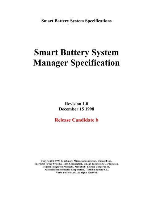
<strong>Smart</strong> <strong>Battery</strong> <strong>System</strong> <strong>Specification</strong>s<strong>Smart</strong> <strong>Battery</strong> <strong>System</strong><strong>Manager</strong> <strong>Specification</strong>Revision <strong>1.0</strong>December 15 1998Release Candidate bCopyright © 1998 Benchmarq Microelectronics Inc., Duracell Inc.,Energizer Power <strong>System</strong>s, Intel Corporation, Linear Technology Corporation,Maxim Integrated Products, Mitsubishi Electric Corporation,National Semiconductor Corporation, Toshiba <strong>Battery</strong> Co.,Varta Batterie AG. All rights reserved.
Questions and comments regarding this specificationmay be forwarded to:Email: selector@sbs-forum.orgOr: questions@sbs-forum.orgFor additional information on <strong>Smart</strong><strong>Battery</strong> <strong>System</strong> <strong>Specification</strong>s, visit theSBS Implementer’s Forum (SBS-IF) at:www.sbs-forum.orgTHIS SPECIFICATION IS PROVIDED "AS IS" WITH NO WARRANTIES WHATSOEVER,INCLUDING ANY WARRANTY OF MERCHANTABILITY, NONINFRINGEMENT, FITNESS FOR ANYPARTICULAR PURPOSE, OR ANY WARRANTY OTHERWISE ARISING OUT OF ANY PROPOSAL,SPECIFICATION OR SAMPLE. THE AUTHORS DISCLAIMS ALL LIABILITY, INCLUDINGLIABILITY FOR INFRINGEMENT OF ANY PROPRIETARY RIGHTS, RELATING TO USE OFINFORMATION IN THIS SPECIFICATION. NO LICENSE, EXPRESS OR IMPLIED, BY ESTOPPEL OROTHERWISE, TO ANY INTELLECTUAL PROPERTY RIGHTS IS GRANTED HEREIN.IN NO EVENT WILL ANY SPECIFICATION CO-OWNER BE LIABLE TO ANY OTHER PARTY FORANY LOSS OF PROFITS, LOSS OF USE, INCIDENTAL, CONSEQUENTIAL, INDIRECT OR SPECIALDAMAGES ARISING OUT OF THIS AGREEMENT, WHETHER OR NOT SUCH PARTY HADADVANCE NOTICE OF THE POSSIBILITY OF SUCH DAMAGES. FURTHER, NO WARRANTY ORREPRESENTATION IS MADE OR IMPLIED RELATIVE TO FREEDOM FROM INFRINGEMENT OFANY THIRD PARTY PATENTS WHEN PRACTICING THE SPECIFICATION.
<strong>Smart</strong> <strong>Battery</strong> <strong>System</strong> <strong>Manager</strong> <strong>Specification</strong>Table of Contents1. INTRODUCTION 11.1. Scope 11.2. Audience 12. REFERENCES 13. DEFINITIONS 24. SMART BATTERY SYSTEM MANAGER 24.1. <strong>Smart</strong> <strong>Battery</strong> <strong>System</strong> <strong>Manager</strong> Requirements and Considerations 34.1.1. Powered by the <strong>Battery</strong> Subsystem 34.1.2. Powered by AC 44.1.3. Implementation Guidelines 54.2. <strong>Smart</strong> <strong>Battery</strong> <strong>System</strong> <strong>Manager</strong> Model 54.3. Interface Requirements 74.4. <strong>Smart</strong> <strong>Battery</strong> <strong>System</strong> <strong>Manager</strong> Functional Requirements 74.5. <strong>Smart</strong> <strong>Battery</strong> <strong>System</strong> <strong>Manager</strong> and Composite <strong>Battery</strong> Reporting 84.5.1. <strong>Battery</strong> Data Composition Guidelines 84.5.2. <strong>Smart</strong> <strong>Battery</strong> <strong>System</strong> <strong>Manager</strong> Data Caching Guidelines 94.5.3. <strong>Smart</strong> <strong>Battery</strong> <strong>System</strong> <strong>Manager</strong> Command Intercepts 115. SMART BATTERY SYSTEM MANAGER INTERFACE 125.1. <strong>Battery</strong><strong>System</strong>State (0x01) 125.2. <strong>Battery</strong><strong>System</strong>StateCont (0x02) 145.3. <strong>Battery</strong><strong>System</strong>Info (0x04) 176. EXAMPLE IMPLEMENTATIONS 196.1. <strong>Battery</strong> Charging Topologies 196.1.1. Single charger / multiple battery topology #1 196.1.2. Multiple charger / multiple battery topology 206.1.3. Single charger / multiple battery topology #2 21APPENDIX A. THE COMMAND SET IN TABULAR FORM 22APPENDIX B. INTERCEPT COMMAND CATEGORIES 22SBS Implementers Forum Page i Revision <strong>1.0</strong>
<strong>Smart</strong> <strong>Battery</strong> <strong>System</strong> <strong>Manager</strong> <strong>Specification</strong>Revision HistoryRevision Number Date Author Notes<strong>1.0</strong> 12/15/98 S Fukatsu/R Dunstan Version <strong>1.0</strong> releaseSBS Implementers Forum Page ii Revision <strong>1.0</strong>
<strong>Smart</strong> <strong>Battery</strong> <strong>System</strong> <strong>Manager</strong> <strong>Specification</strong>3. Definitions• ACPI: Advanced Configuration and Power Interface.• APM: Advanced Power Management. A BIOS interface defined to enable system-wide powermanagement control via software.• <strong>Battery</strong>: One or more cells that are designed to provide electrical power.• Cell: The cell is the smallest unit in a battery. Most batteries consist of several cells connected inseries.• EC: Embedded Controller as defined in chapter 13 of the ACPI specification.• I²C-bus: A two-wire bus developed by Phillips, used to transport data between low-speed devices.• <strong>Smart</strong> <strong>Battery</strong>: A battery equipped with specialized hardware that provides present state, calculatedand predicted information to its SMBus Host under software control.• <strong>Smart</strong> <strong>Battery</strong> Charger: A battery charger that periodically communicates with a <strong>Smart</strong> <strong>Battery</strong> andalters its charging characteristics in response to information provided by the <strong>Smart</strong> <strong>Battery</strong>.• <strong>Smart</strong> <strong>Battery</strong> Selector: A device that arbitrates between two or more <strong>Smart</strong> Batteries. It controls thepower and SMBus paths between the SMBus Host, a <strong>Smart</strong> Charger and the <strong>Smart</strong> Batteries.• <strong>Smart</strong> Device: An electronic device or module that communicates over the SMBus with the SMBusHost and/or other <strong>Smart</strong> Devices. For example the back light controller in a notebook computer can beimplemented as a <strong>Smart</strong> Device.• SMBus: The <strong>System</strong> Management Bus is a specific implementation of an I²C-bus that describes dataprotocols, device addresses and additional electrical requirements that is designed to physicallytransport commands and information between the <strong>Smart</strong> <strong>Battery</strong>, SMBus Host, <strong>Smart</strong> <strong>Battery</strong> Chargerand other <strong>Smart</strong> Devices.• SMBus Host: A piece of portable electronic equipment powered by a <strong>Smart</strong> <strong>Battery</strong>. It is able tocommunicate with the <strong>Smart</strong> <strong>Battery</strong> and use information provided by the battery.• Packet Error Check (PEC): An additional byte in the SMBus protocols used to check for errors in anSMBus transmission. Refer to the <strong>System</strong> Management Bus <strong>Specification</strong> Revision 1.1. A <strong>Smart</strong><strong>Battery</strong> <strong>System</strong> <strong>Manager</strong> indicates its ability to support PEC with theBATTERY_SYSTEM_REVISION value in <strong>Battery</strong><strong>System</strong>Info() function.4. <strong>Smart</strong> <strong>Battery</strong> <strong>System</strong> <strong>Manager</strong>Why is a <strong>Smart</strong> <strong>Battery</strong> <strong>System</strong> <strong>Manager</strong> (SBSM) necessary? It would seem that the obvious method foradding an additional <strong>Smart</strong> <strong>Battery</strong> to any system would be simply to allocate an additional SMBus addressfor the second battery. Unfortunately, this is not a practical solution; the SMBus address is merely one partof the system, defining the data path for <strong>Smart</strong> <strong>Battery</strong> data transactions between the SMBus host, the <strong>Smart</strong><strong>Battery</strong> Charger and the <strong>Smart</strong> <strong>Battery</strong> itself. Other significant connections are required, both to reportcorrect information and to maintain system safety.In most multiple-battery systems today, some device or mechanism is present to arbitrate between thebatteries. Additionally, this device must be able to dynamically re-configure the system’s power systemwith sufficient speed to prevent any side effects caused by removal of the system’s primary battery. A usermay neither know nor care which battery is powering their system, but they do expect that their system willkeep on working. For example, in a system where a slot is shared between a battery and a floppy disk drive,the user may simply remove the battery to install the floppy drive. If the battery in the shared slot waspowering this example system, the device must be able to switch to the other battery quickly enough that thesystem’s power integrity is not compromised.The system (notebook) needs to be informed when there is a change in the battery system. For example, thepresence of AC could signal the system that it is possible to start charging or a battery calibration cycle orsimply change the back light settings of the LCD display. The addition of another battery should signal thesystem that additional operating time maybe available. The removal of a battery should signal the system tomake sure that there is enough energy to maintain system and data integrity. At a higher level, the operatingsystem (OS) needs to be informed when ever there has been a change in the battery system’s state. This isSBS Implementers Forum Page 2 Revision <strong>1.0</strong>
<strong>Smart</strong> <strong>Battery</strong> <strong>System</strong> <strong>Manager</strong> <strong>Specification</strong>required so that the OS can accurately reflect the state of the system to the user and to make appropriatepower management decisions.The SBSM described in this specification can provide this level of functionality.4.1. <strong>Smart</strong> <strong>Battery</strong> <strong>System</strong> <strong>Manager</strong> Requirements and ConsiderationsThere are several requirements for a system operating from battery power in a multiple-battery system.These requirements ensure system safety, data accuracy and data integrity.In all situations:• <strong>Battery</strong><strong>System</strong>State() will always return the actual state of SBSM. Software may use this feature toverify that a previous request was valid.• In the case of a SBSM that supports simultaneous charging/discharging, the <strong>Battery</strong><strong>System</strong>State() willreport each battery’s presence or absence and whether the battery is powering the system or connectedto the <strong>Smart</strong> <strong>Battery</strong> Charger.• The SBSM will select the proper battery or combination of batteries to power the system immediatelywhen external power is removed or fails. This must be done autonomously and a<strong>Battery</strong><strong>System</strong>State()notification sent to the system host by whatever mechanism is used within a givenimplementation.• The SBSM will have an external input that when asserted, will inhibit any and all charging activity.This input provides a hardware input that may be used prohibit charging . It has the same effect assetting the <strong>Battery</strong><strong>System</strong>StateCont() CHARGING_INHIBIT bit. Note that when this input is asserted,the <strong>Battery</strong><strong>System</strong>StateCont() CHARGING_INHIBIT bit will return a 1. When this input is returnedto its non-asserted state, the <strong>Battery</strong><strong>System</strong>StateCont() CHARGING_INHIBIT bit will be returned toits previous state.4.1.1. Powered by the <strong>Battery</strong> SubsystemWhen operating from battery power:• The power output of unselected batteries must be isolated from the system power supply. This isnecessary to prevent potentially high-current conditions that can occur if two or more batteries withdifferent characteristics or states are simply connected together. However, legal topologies can becreated where two or more batteries may be discharged simultaneously. In this case, the SBSM musthave circuitry to prevent potentially dangerous current flows between the batteries in use.• The SBSM must maintain an SMBus connection between the battery or batteries powering the systemand the system host. This ensures the integrity of AlarmWarning() messages between the battery(s) inuse and the system host. These warnings from battery(s) not in use may be ignored. In the case ofsimultaneous discharging or charging, the SBSM is responsible to create a “composite” critical alarmfrom the batteries in use and must send the composite critical messages to the system host. Thecomposite critical message is the bit-wise, logical-OR of AlarmWarning() messages from the individualbatteries.• The host must be able to communicate individually with every battery in the system to determine itscapacity, etc., without interfering with the normal operation of the battery(s) powering the system. Thisfeature enables user oriented displays that show the condition of every battery in the system, not justthe active one(s).• The SBSM must provide autonomous switchover functions between batteries to prevent system powerfailure.• In multiple-battery systems, when one of the batteries in use fails or is removed, the SBSM mustmaintain the system’s power integrity. It may use one or more of the remaining batteries to power thesystem. These actions must take place without host intervention and without compromising safety.• When the SBSM determines that the configuration has changed for any reason, the SMBus host mustbe notified that a change has occurred. There are two acceptable methods:1. The SBSM masters the SMBus to the host and writes its <strong>Battery</strong><strong>System</strong>State() register to theSMBus host (SMBus WriteWord protocol to the SMBus Host with the command code set to theselector’s address 0x14).SBS Implementers Forum Page 3 Revision <strong>1.0</strong>
<strong>Smart</strong> <strong>Battery</strong> <strong>System</strong> <strong>Manager</strong> <strong>Specification</strong>Note: The SBSM will issue a <strong>Battery</strong><strong>System</strong>State() notification for any change in the battery/powersystem status, including changes in the <strong>Battery</strong><strong>System</strong>StateCont(). It is the responsibility of the OSdriver to query the status of both the <strong>Battery</strong><strong>System</strong>State() and <strong>Battery</strong><strong>System</strong>StateCont() in order todetermine the exact reason for the notification (e.g. change in the AC status).2. The SBSM may notify the system independent of the SMBus by using a signal line that wouldcause the host to query the SBSM’s <strong>Battery</strong><strong>System</strong>State() and the <strong>Battery</strong><strong>System</strong>StateCont(. Thissignal line may be connected either to an interrupt or it may be polled by the SMBus host or otherfirmware on the system platform. In all cases, the host must be notified by the SBSM whenever achange occurs. The implementation is at the option of the system’s designer.4.1.2. Powered by ACWhen operating from an externally supplied power source (AC), there is another set of requirements for amultiple-battery systems. As in the previous case, there are potentially harmful side-effects if any of thefollowing are ignored while operating from external power:• The SBSM must be able to isolate the power output of all batteries from external power. This isnecessary to prevent uncontrolled currents into or out of the batteries.• The SMBus and Safety Signal connections must be properly maintained through the SBSM so that anyand all batteries in the system are charged safely.:1. Monitor the SMBus connection between the SBSM and each smart battery in a way thatensures proper charging voltage and charging current is applied to each battery in a safemanner. Either ChargingVoltage() and ChargingCurrent() must be received from the batteryor polled by the SBSM in a regular fashion. Refer to the <strong>Smart</strong> <strong>Battery</strong> and <strong>Smart</strong> <strong>Battery</strong>Charger specification for more details.2. Monitor the SMBus connections in a manner that ensures all AlarmWarning() messages fromthe battery are received by both the system host AND the appropriate <strong>Smart</strong> <strong>Battery</strong> charger.Alternatively, the system host or EC can regularly polls all the involved <strong>Smart</strong> <strong>Battery</strong>’s<strong>Battery</strong>Status() registers to ensure safe charging. The EC or system host must both send theAlarmWarning() messages to the host and ensure that AlarmWarning() messages are sent tothe <strong>Smart</strong> <strong>Battery</strong> charger that is charging the <strong>Smart</strong> <strong>Battery</strong> sending the messages.3. Each battery connected to a charger must have its safety signal appropriately monitored. Thesafety signal is an independent mechanism used to terminate or limit charge when the SMBusfails (primary safety mechanism). Failure to connect the safety signal to the SBSM defeatsthis method and may result in an unsafe system. The battery safety signal(s) must becontinually monitored by the charger or chargers that are sourcing power to each <strong>Smart</strong><strong>Battery</strong> being charged. This connection ensures out-of-band charge termination information isactually coming from the <strong>Smart</strong> <strong>Battery</strong> receiving power from the charger. This does notnecessarily mean that one charger may charge only one battery. In cases where one charger isused to charge more than one battery, it must respond to any charge termination signalreceived from the batteries being charged. The charge termination message or signal may bean AlarmWarning(), other SBS command that inhibits charging or the safety signal changingits state.To summarize, requirements for battery system safety during charging are:1. The <strong>Smart</strong> <strong>Battery</strong> Charger must regularly receive or poll for charging voltage and current from allbatteries that are being charged.2. The SMBus host must have the capability to receive an AlarmWarning() from a battery beingcharged or must poll the battery’s <strong>Battery</strong>Status().3. The <strong>Smart</strong> <strong>Battery</strong>’s safety signal(s) must be continually monitored by the charger or chargers thatare sourcing power to each battery being charged.Any topology that is in conflict with the above, may be unsafe and is forbidden. SBSMs that allowforbidden topologies are NOT compliant with the <strong>Smart</strong> <strong>Battery</strong> <strong>System</strong> <strong>Manager</strong> specifications.SBS Implementers Forum Page 4 Revision <strong>1.0</strong>
<strong>Smart</strong> <strong>Battery</strong> <strong>System</strong> <strong>Manager</strong> <strong>Specification</strong>4.1.3. Implementation GuidelinesTo accomplish these tasks, the SBSM can be implemented in many ways. One very simple system is acollection of five switches that control the SMBus (data), the safety signal, and power:• <strong>Battery</strong> output power• Charger output power• <strong>Battery</strong>-to-charger data• <strong>Battery</strong>-to-charger safety signal• Host-to-battery dataA more complex SBSM could be a combination micro-controller based system that has:• One SMBus port for each <strong>Smart</strong> <strong>Battery</strong>• Emulates the <strong>Smart</strong> <strong>Battery</strong> Charger function• Provides the <strong>Smart</strong> <strong>Battery</strong> <strong>System</strong> <strong>Manager</strong> functionality• Acts as the SMBus host.An SBSM that supports either simultaneous charging and./or discharging have additional capabilities.SBSMs that allow simultaneous discharge must also have the capability to:• Report data from a composite of the batteries supplying power• Report a composite of the alarms from the batteries supplying powerSBSMs that allow simultaneous charge must also have the capability to:• Report a composite of the alarms from the battery(s) being charged power to both the SMBus hostAND the charger(s)• Maintain constant monitoring of the safety signal(s)• Maintain the correct connections between the battery and charger for power, SMBus data and safetysignal.4.2. <strong>Smart</strong> <strong>Battery</strong> <strong>System</strong> <strong>Manager</strong> ModelOne possible, simple <strong>Smart</strong> <strong>Battery</strong> <strong>System</strong> <strong>Manager</strong> model is a system consisting of two <strong>Smart</strong> Batteries, a<strong>Smart</strong> <strong>Battery</strong> Charger and the SBSM in a notebook computer. The diagram below illustrates the typicalpower and data paths when battery A is acting as the primary battery. This diagram shows a <strong>Smart</strong> <strong>Battery</strong><strong>System</strong> <strong>Manager</strong> connecting <strong>Smart</strong> <strong>Battery</strong> A to both the system and the charger. When AC is present, the<strong>Smart</strong> <strong>Battery</strong> can opt to charge itself as required and the system will be powered by the AC source. If ACis not present, the system will be powered by <strong>Smart</strong> <strong>Battery</strong> A.This is exactly the same model used by the <strong>Smart</strong> <strong>Battery</strong> Selector. The differences are in the reportinginterface to the system.SBS Implementers Forum Page 5 Revision <strong>1.0</strong>
<strong>Smart</strong> <strong>Battery</strong> <strong>System</strong> <strong>Manager</strong> <strong>Specification</strong>Vcc,+12v, -12v<strong>System</strong>PowerSupplyDC(Unregulated/battery)PowerSwitchNote: SB A charging/powering thesystemSB B idleAC<strong>Smart</strong> <strong>Battery</strong> A<strong>Smart</strong> <strong>Battery</strong> BAC-DCConverter(Unregulated)VbattThermistorSMBusVbattThermistorSMBus<strong>System</strong> Host<strong>Smart</strong> <strong>Battery</strong><strong>System</strong> <strong>Manager</strong>SMBusThermistor<strong>Smart</strong> <strong>Battery</strong>ChargerVChargeCritical Events<strong>Battery</strong> Data/Status RequestsSMBusSimple Multiple <strong>Smart</strong> <strong>Battery</strong> <strong>System</strong>The following diagram is a block diagram of a SBSM, <strong>Smart</strong> <strong>Battery</strong> Charger and SMBus host as addedfunctionality to the EC (embedded controller). <strong>Smart</strong> <strong>Battery</strong> A and/or B are available to power the system.The power path configuration block is used by the SBSM to select which battery is used to power thesystem: <strong>Smart</strong> <strong>Battery</strong> A, <strong>Smart</strong> <strong>Battery</strong> B or a combination of both <strong>Smart</strong> Batteries A and B. Thealgorithm used is selected by the system’s designer and is contained in the SBSM. If AC is present, theSBSM may chose to charge either <strong>Smart</strong> <strong>Battery</strong> A or B or both. Again, the algorithm used is containedentirely within the SBSM.The safety signal combiner ensures that the <strong>Smart</strong> <strong>Battery</strong> Charger’s alternative safety signaling path isalways maintained.The SMBus router ensures that the operating system can communicate with individual batteries as well asthe composite of batteries being discharged simultaneously. There is no requirement for the compositebattery data to be generated within the EC. Other alternatives such as a private interface between the ECand the OS that would allow a custom driver to calculate composite battery data are allowed. The SMBusrouter also ensures that the operating system receives all alarms from the battery or batteries being chargedor discharged.It is important to note, that while functions, such as the <strong>Smart</strong> <strong>Battery</strong> charger are shown as discrete blocks,their respective functionality may be emulated by the EC in combination with other hardware.SBS Implementers Forum Page 6 Revision <strong>1.0</strong>
<strong>Smart</strong> <strong>Battery</strong> <strong>System</strong> <strong>Manager</strong> <strong>Specification</strong>V 1V 2V 3DC-DCConverterV 4V UNREGULATEDTPowerSwitchAC-DCConverter<strong>Smart</strong> <strong>Battery</strong> AT<strong>Smart</strong> <strong>Battery</strong> BV BATTV BATT<strong>System</strong> Host(EC)PowerConfigurationSMBusRouter&CompositedataV CHARGERSafety SignalCombiner<strong>Smart</strong> <strong>Battery</strong>ChargerT<strong>Smart</strong> <strong>Battery</strong><strong>System</strong> <strong>Manager</strong>SMBusCritical Events / State ChangesSelect <strong>Battery</strong>(s) andData CommandsSBSM Combined with embedded controller4.3. Interface RequirementsThe software interface consists of the primary read/write control register, an optional read/write controlregister, and a read-only register. The SBSM may be implemented as an SMBus slave-only device,however it may be implemented as a master and send a <strong>Battery</strong><strong>System</strong>State() notification to the SMBus hostafter every state change.4.4. <strong>Smart</strong> <strong>Battery</strong> <strong>System</strong> <strong>Manager</strong> Functional RequirementsThe SBSM must provide the following services:• The SBSM will do a power-on default to connect one or more batteries to power the system if AC isnot present and connect one or more batteries to their respective chargers if AC is present.• The SBSM will monitor the discharging batteries’ terminal voltages and if any falls below a presetminimum. It will autonomously switch to another battery or batteries (if any are present) or reconfigurethe simultaneous discharge configuration. The SBSM will update its <strong>Battery</strong><strong>System</strong>State() and the<strong>Battery</strong><strong>System</strong>StateCont() to reflect any changes and notify the system the <strong>Battery</strong><strong>System</strong>State() and/orthe <strong>Battery</strong><strong>System</strong>StateCont() has changed. In slave only implementations, this may be accomplishedin several ways:• The SMBus host polls the SBSM’s <strong>Battery</strong><strong>System</strong>State() and <strong>Battery</strong><strong>System</strong>StateCont() for changesSBS Implementers Forum Page 7 Revision <strong>1.0</strong>
<strong>Smart</strong> <strong>Battery</strong> <strong>System</strong> <strong>Manager</strong> <strong>Specification</strong>• The SBSM uses the #SMBALERT mechanism to notify the SMBus host that a state changeoccurred. The SMBus host will then have to determine that the SBSM signaled the change and thenread and pass on the contents of the <strong>Battery</strong><strong>System</strong>State() to the system via the EC interface.• The SBSM uses an interrupt connected to a micro-controller such as the EC. When an interrupt isdetected, it causes the <strong>Battery</strong><strong>System</strong>State() to be read and passes the contents to the system via theEC interface.• The SBSM will monitor the presence of the discharging battery(s) and, if it is removed, it willautonomously switch to another battery (or batteries) present. In systems with simultaneous dischargeenabled, the SBSM will modify the configuration when any of the batteries being discharged isremoved. The SBSM will update its <strong>Battery</strong><strong>System</strong>State() register to reflect the change and notify thesystem that its <strong>Battery</strong><strong>System</strong>State() has changed.• If no batteries are powering the system as indicated by the status bits in POWERED_BY_X and thereis an event that causes a <strong>Battery</strong><strong>System</strong>State() change• if required the SBSM will autonomously switch to the next viable battery or simultaneousdischarge configuration• update its <strong>Battery</strong><strong>System</strong>State() register to reflect the change• notify the system that its <strong>Battery</strong><strong>System</strong>State has changed.• The charger connection is the sole responsibility of the <strong>Smart</strong> <strong>Battery</strong> <strong>System</strong> <strong>Manager</strong>. The SBSMmust report whether AC is present or not, and if it changes, the SBSM must update its<strong>Battery</strong><strong>System</strong>StateCont() register to reflect the change and notify the system that its<strong>Battery</strong><strong>System</strong>State() has changed. Note: The SBSM renders the ChargerMode() and ChargerStatus()registers redundant from the Operating <strong>System</strong>’s perspective.• It is expected that the SBSM will operate in an entirely autonomous manner, independent of any highlevelcontrol such as that provided by an application or system BIOS. This autonomy allows thesystem to charge multiple batteries while the host intelligence is not operational (e.g., when the systemis off or suspended). Since the SBSM operates autonomously, it is totally responsible for the batterysystem’s safe operation and for maintaining the power integrity of the system.In all cases, the SBSM’s primary purpose is to ensure safe operation of the battery system and to maintainsystem power and minimize interruptions to that power. Its secondary purpose is to inform (or makeinformation available to) the SMBus host about the system’s <strong>Battery</strong><strong>System</strong>State and changes in that<strong>Battery</strong><strong>System</strong>State.4.5. <strong>Smart</strong> <strong>Battery</strong> <strong>System</strong> <strong>Manager</strong> and Composite <strong>Battery</strong> ReportingThe SBSM is a component that owns the battery system. In some implementations, it may allow more thanone battery to supply power simultaneously. This creates problems for the operating system as it does notnecessarily have a means to accurately put together data from two or more batteries being discharged at thesame time. The SBSM must have the ability to report composite battery data of the active batteries whenmore than one battery is powering the system simultaneously.The SBSM is not required to support simultaneous discharge, but if it does, it assumes the burden to mergeand report the battery system’s composite data.4.5.1. <strong>Battery</strong> Data Composition GuidelinesDuring simultaneous charging, the SBSM must have the ability to create a composite alarm of theindividual batteries being charged. At a minimum, when any individual battery being charged issues analarm, it must be passed through to the system host and charger. The charger(s) must subsequently stopscharging if any battery’s charging alarm bit defined in the <strong>Smart</strong> <strong>Battery</strong> Charger specification (includingany reserved bits) is set.During simultaneous discharging, the SBSM must logically OR the alarms of the individual batteries beingdischarged. At a minimum, when any individual battery being discharged issues an alarm, it must be passedthrough to the host including any reserved bits with the alarm values of the rest of the batteries beingdischarged as defined in the <strong>Smart</strong> <strong>Battery</strong> Data <strong>Specification</strong>.SBS Implementers Forum Page 8 Revision <strong>1.0</strong>
<strong>Smart</strong> <strong>Battery</strong> <strong>System</strong> <strong>Manager</strong> <strong>Specification</strong>During Simultaneous discharge, the SBSM should appear to the system host as either one battery orindividual batteries if specific information is requested or directed to or from a particular battery. Thisrequirement appears across the entire <strong>Smart</strong> <strong>Battery</strong> data set. Individual implementations may change thealgorithms used to combine or merge data. The SBSM interface provides the means to access either thecombined data or individual data.Examples of battery data composition may be the MaxError() command. If the system host requestsMaxError() and the SBSM is in a mode where battery composition is operating, the specific implementationmay choose to report the RMS (root mean squared value of all MaxError() values.4.5.2. <strong>Smart</strong> <strong>Battery</strong> <strong>System</strong> <strong>Manager</strong> Data Caching GuidelinesIn order to preserve bandwidth on the system host SMBus, the SBSM may employ a cache for dynamic andstatic composite battery data. Dynamic data values are those that change or are expected to change duringthe mobile PC operation, e.g., Current(). Static values are those that remain the same as long as the batteryis not removed or replaced, e.g., SerialNumber().In order to preserve data integrity and currency, the SBSM needs to apply reasonable refresh rules to anycached values. Generally stated these rules are:• Static values may be cached and re-read without limit as long as the SBSM has not been reset or thebattery exchanged, removed or newly inserted. In any of these cases, the SBSM must refresh the staticdata in any cache it may maintain and notify the system host as advised in earlier in this specification.• Dynamic data values may be cached in expectation of a system host request. Dynamic data must berefreshed after being read once. Further, the SBSM must flag an error (not respond or indicate staledata) or use any mechanism available in the physical layer to avoid or delay the response until freshdata is available and combined according to the implementation algorithm rules.• The SBSM must refresh dynamic data at appropriate intervals suggested in the following table so thatdata is not stale. The timeout period for this refresh is governed by specific OEM implementations.The following table is a guide to what battery data should be cached and when the cache should beinvalidated or updated.Function Access Composite Cacheable CacheInvalidate (inaddition tobatteryinsertion)ManufacturerAccess r/w no NoRemainingCapacityAlarm* r/w yes Yes On writeRemainingTimeAlarm* r/w yes Yes On write<strong>Battery</strong>Mode r/w yes Yes On writeAtRate r/w yes Yes On writeAtRateTimeToFull r no Yes Write to AtRate or 1minute (chargeonly)AtRateTimeToEmpty* r yes (dischargeonly)AtRateOK* r yes (dischargeonly)Yes Write to AtRate or 1minute (dischargeonly)NoCache Update(next accessOR …)SBS Implementers Forum Page 9 Revision <strong>1.0</strong>
<strong>Smart</strong> <strong>Battery</strong> <strong>System</strong> <strong>Manager</strong> <strong>Specification</strong>Temperature r Yes Yes 1 minute(charging/discharging) ) or upon a statechangeVoltage r yes Yes 1 minute(charging/discharging) ) or upon a statechangeCurrent r yes NoAverageCurrent r yes NoMaxError r yes Yes or upon a statechangeRelativeStateOfCharge r yes Yes 1 minute(charging/discharging) ) otherwise TBDminutesAbsoluteStateOfCharge r yes Yes 1 minute(charging/discharging) ) otherwise TBDminutesRemainingCapacity r yes Yes 1 minute(charging/discharging) ) otherwise TBDminutesFullChargeCapacity r yes Yes Upon a state changeRunTimeToEmpty* r yes Yes 1 minute(charging/discharging) ) otherwiseTBDminutesAverageTimeToEmpty* r yes Yes 1 minute(charging/discharging) ) otherwise TBDminutesAverageTimeToFull r no Yes 1 minute (charging)ChargingCurrent r no Yes 1 minute (charging)ChargingVoltage r no Yes 1 minute (charging)<strong>Battery</strong>Status* r yes NoCycleCount r no yes Change from chargeto discharge ordischarge to chargeDesignCapacity r no yesDesignVoltage r no yes<strong>Specification</strong>Info r no yesManufactureDate r no yesSerialNumber r no yesreservedManufacturerName r no yesDeviceName r no yesDeviceChemistry r no yesManufacturerData r no noreservedOptionalMfgFunction5 r/wSBS Implementers Forum Page 10 Revision <strong>1.0</strong>
<strong>Smart</strong> <strong>Battery</strong> <strong>System</strong> <strong>Manager</strong> <strong>Specification</strong>reservedOptionalMfgFunction4OptionalMfgFunction3OptionalMfgFunction2OptionalMfgFunction1r/wr/wr/wr/w<strong>Smart</strong> <strong>Battery</strong> Functions4.5.3. <strong>Smart</strong> <strong>Battery</strong> <strong>System</strong> <strong>Manager</strong> Command InterceptsIn order to preserve bandwidth on the system host SMBus, the SBSM may intercept and respond directly tocommands directed to either the <strong>Smart</strong> <strong>Battery</strong> or the <strong>Smart</strong> <strong>Battery</strong> Charger. When an individual battery ispowering the system or is being charged or whenever individual battery data is desired, the SBSM relaysthe command to the battery and produces the requested data in the most efficient manner possible. TheSBSM may optionally pass <strong>Smart</strong> <strong>Battery</strong> Charger commands through to the charger in the most efficientmeans possible.The SBSM typically intercepts commands directed to the battery or charger whenever simultaneouscharging, simultaneous discharging, or a combination of charging and discharging is taking place in thebattery system. In this case, the SBSM will rely either on cached composite data values or it will have togenerate composite data in real time. During these situations, the SMBus for both the battery and chargerare invisible to the system host.For instance, the SBSM may intercept the SBC ChargerMode() command when in simultaneous chargingmode and make appropriate composition of the charging status. The composite data returned duringsimultaneous discharge should adhere to the relevant SBS specification. The method of data composition isdetermined by the OEM implementation.SBS Implementers Forum Page 11 Revision <strong>1.0</strong>
<strong>Smart</strong> <strong>Battery</strong> <strong>System</strong> <strong>Manager</strong> <strong>Specification</strong>5. <strong>Smart</strong> <strong>Battery</strong> <strong>System</strong> <strong>Manager</strong> InterfaceThe following functions are used by the SMBus Host to communicate with the SBSM and attached <strong>Smart</strong>Batteries.The functions are described as follows:FunctionName() 0xnn (command code)Description:A brief description of the function.Purpose:The purpose of the function, and an example where appropriate.SMBus Protocol: Refer to Section 6 and to the SMBus specification for more details.Input, Output or Input/Output: A description of the data supplied to or returned by the function.Whenever the <strong>Smart</strong> <strong>Battery</strong> <strong>System</strong> <strong>Manager</strong> encounters a valid command with invalid data, it is expectedto do nothing, just ignore the invalid data. For example, if an attempt is made to select battery A and B tosimultaneously communicate with the system host, the SBSM will just ignore the request. This behaviorwill help to prevent errant commands from setting up conditions that might cause damage to the system, orbatteries.The following commands describe the interface the system software expects when communicating with a<strong>Smart</strong> <strong>Battery</strong> <strong>System</strong> <strong>Manager</strong>. It is acceptable for the system BIOS, or some other device in the system,to intercept and emulate some or all of the SBSM commands, provided that the SBSM interface definedbelow is maintained to the system software.5.1. <strong>Battery</strong><strong>System</strong>State (0x01)Description:This required function returns the present state of the <strong>Smart</strong> <strong>Battery</strong> <strong>System</strong> <strong>Manager</strong> and allows access toindividual batteries. The information is broken into four nibbles that report:• Which battery is communicating with the SMBus Host• Which battery(s), if any, or AC is powering the system• Which battery(s) is connected to the <strong>Smart</strong> Charger• Which battery(s) are present.The SBSM provides a mechanism to notify the system whenever there is a change in its state. Specifically,the SBSM will provides the system with a notification whenever:• A battery is added or removed• AC power is connected or disconnected• The SBSM autonomously changes the configuration of the battery(s) supplying power• The SBSM autonomously changes the configuration of the battery(s) being chargedThis function provides simultaneous access to four nibble-wide registers of the following types:• One to control the communications path between the SMBus host and a specific battery• One to show the status of the battery(s) powering the system• One to show the status of the battery(s) being charged• One to show the status of the battery(s) present in the systemPurpose:Used by the system host to determine the present state of the <strong>Smart</strong> <strong>Battery</strong> <strong>System</strong> <strong>Manager</strong> and theattached batteries. It also may be used to determine the state of the battery system after the SBSM notifiesthe system of a change.SBS Implementers Forum Page 12 Revision <strong>1.0</strong>
<strong>Smart</strong> <strong>Battery</strong> <strong>System</strong> <strong>Manager</strong> <strong>Specification</strong>SMBus Protocol: Read or Write WordInput/Output: word -- bit flags in nibbles mapped as follows:SMB(r/w)<strong>Battery</strong>(s)connected toSMBus host(comm.)POWER_BY(r)<strong>Battery</strong>(s)Powering the<strong>System</strong>(power & comm.)CHARGE(r)<strong>Battery</strong>(s)Charging(power & comm.)PRESENT(r)<strong>Battery</strong>(s) PresentD C B A D C B A D C B A D C B ASMB_X nibbleThe read/write SMB_X nibble is used by the SMBus Host to select which individual battery tocommunicate with or to determine which individual battery or composite battery it is communicating with.Normally, this nibble is set to the same value as the POWER_BY_X nibble.For example, an application that displays the remaining capacity of all batteries would write to this nibble toindividually select each battery in turn and get its capacity. The bits are defined as follows:0xf000 select all SMBus host is communicating with a composite of the battery(s) powering the system.0x8000 SMB_D SMBus Host is communicating with <strong>Battery</strong> D0x4000 SMB_C SMBus Host is communicating with <strong>Battery</strong> C0x2000 SMB_B SMBus Host is communicating with <strong>Battery</strong> B0x1000 SMB_A SMBus Host is communicating with <strong>Battery</strong> ANote: On a write to this nibble, only one or all bits may be set. In the first case, the SMBus hostcommunicates with the specified individual battery. In the second case, the SBSM will return a compositepicture of the battery system. The battery(s) forming the composite can be determined by examining thecontents of the POWER_BY_X nibble. The SBSM can not be forced to read any arbitrary set of batteriesand is responsible to present composite data only for battery combinations it selects.Note: Writes of values other than 0x1000, 0x2000, 0x4000, 0x8000, and 0xf000 are not allowedThe operating system will read this nibble to determine which battery it is actually communicating with toensure that it is connected to the desired battery(s).0xf000 Composite mode SMBus host is communicating with a composite of the battery(s) powering thesystem.0x8000 SMB_D SMBus Host is communicating with <strong>Battery</strong> D0x4000 SMB_C SMBus Host is communicating with <strong>Battery</strong> C0x2000 SMB_B SMBus Host is communicating with <strong>Battery</strong> B0x1000 SMB_A SMBus Host is communicating with <strong>Battery</strong> AIn composite mode, refer to the POWER_BY_X nibble to determine the composite batteries that make updischarging related data values. Composite data values are not returned for batteries during simultaneouscharging. See the Appendix X for a classification of which data values fall into which category.POWER_BY_X nibbleThe read only POWER_BY_X nibble is used by the SMBus Host to determine which battery(s) is poweringthe system. All writes to this nibble will be ignored.0x0800 POWER_BY_D <strong>System</strong> being powered by <strong>Battery</strong> D.0x0400 POWER_BY_C <strong>System</strong> being powered by <strong>Battery</strong> C.0x0200 POWER_BY_B <strong>System</strong> being powered by <strong>Battery</strong> B.0x0100 POWER_BY_A <strong>System</strong> being powered by <strong>Battery</strong> A.0x0000 POWER_BY_AC <strong>System</strong> being powered by AC.Note: Each bit in the POWER_BY_X nibble will be set independently to indicate which batteries, if any,are powering the system. For example:0x0300 POWER_BY_A and POWER_BY_B <strong>System</strong> being powered by battery A and B simultaneouslySBS Implementers Forum Page 13 Revision <strong>1.0</strong>
<strong>Smart</strong> <strong>Battery</strong> <strong>System</strong> <strong>Manager</strong> <strong>Specification</strong>CHARGE_X nibbleThe read only CHARGE_X nibble is used by the SMBus Host to determine which, if any, battery is beingcharged. All writes to this nibble will be ignored.The bits are defined as follows:0x0080 CHARGE_D <strong>Battery</strong> D being charged0x0040 CHARGE_C <strong>Battery</strong> C being charged0x0020 CHARGE_B <strong>Battery</strong> B being charged0x0010 CHARGE_A <strong>Battery</strong> A being charged0x0000 No <strong>Battery</strong> being chargedNote: Each bit in the CHARGE_X nibble will be set independently to indicate which batteries are actuallybeing charged. For example:0x0030 CHARGE_A and CHARGE_B Batteries A and B are being simultaneously charged.An indication that multiple batteries are being charged simultaneously does not indicate that the batteriesare being charged at the same rate or that they will complete their charge at the same time. To actuallydetermine when an individual battery will be fully charged, use the SMB_X nibble to individually select thebattery of interest and read the TimeToFull() value.PRESENT_X nibbleThe read only PRESENT_X nibble is used by the SMBus Host to determine how many and which batteriesare present. All writes to this nibble will be ignored.The bits are defined as follows:0x0008 PRESENT_D <strong>Battery</strong> D is present0x0004 PRESENT_C <strong>Battery</strong> C is present0x0002 PRESENT_B <strong>Battery</strong> B is present0x0001 PRESENT_A <strong>Battery</strong> A is presentNote: Each bit in the PRESENT_X nibble will be set independently to indicate the presence of a battery.5.2. <strong>Battery</strong><strong>System</strong>StateCont (0x02)Description:This required function returns additional state information of the <strong>Smart</strong> <strong>Battery</strong> <strong>System</strong> <strong>Manager</strong> andprovides an interface to prohibit charging. This command also removes any requirement for the operatingsystem to communicate directly with the charger to obtain AC presence information. When the SBSM isused, access to the charger address, 0x12, is blocked.Purpose:Used by the system host to determine the retrieve additional state information from the <strong>Smart</strong> <strong>Battery</strong><strong>System</strong> <strong>Manager</strong> and the overall system power configuration. It may also be used by the system to prohibitany battery charging. This feature may be used in conjunction with a special power cable for example toprohibit charging in situations where charging is not allowed.SMBus Protocol: Read or Write WordInput/Output: word -- bit flags mapped as follows:FieldBitsUsedFormatAllowable ValuesSBS Implementers Forum Page 14 Revision <strong>1.0</strong>
<strong>Smart</strong> <strong>Battery</strong> <strong>System</strong> <strong>Manager</strong> <strong>Specification</strong>AC_PRESENT 0 Bit flag The AC_PRESENT bit returns a 1 when the SBSMdetermines that AC is present. It returns to 0 when AC isremoved. Any change in this bit causes an SBSM statechange. Writes to this bit have no effectPOWER_NOT_GOOD 1 Bit Flag The POWER_NOT_GOOD bit returns 1 when the ACpower is too low to supply adequate power to the system.Writes to this bit have no effect.CALIBRATE_REQUEST_SUPPORT2 Bit Flag The optional CALIBRATE_REQUEST_SUPPORT bitreturns 1 when the SBSM has the ability to detectbatteries needing a calibration cycle. Writes to this bithave no effect.CALIBRATE_REQUEST 3 Bit Flag The optional CALIBRATE_REQUEST bit returns 1when the SBSM determines one or more batteries requirea calibration cycle. Writes to this bit have no effect.CHARGING_INHIBIT 4 Bit flag The CHARGING_INHIBIT bit returns a 0 when chargingis allowed and returns a 1 when charging is inhibited.This bit may be written to by the host to inhibit or allowcharging. The default value of this bit is 0.CHARGER_POR 5 Bit Flag The CHARGER_POR bit always returns 0. Writing a 1to this bit forces a power on reset of the charger.CALIBRATE 6 Bit Flag The optional CALIBRATE bit returns 0 when a batterycalibration cycle is not in progress. This bit may bewritten to by the host to initiate a calibration cycle (fullydischarging the battery followed by charging the battery).When the CALIBRATE_REQUEST bit is set, writing a 1to this bit enables the SBSM to begin calibrating anybattery when AC is present. The CALIBRATE bit willbe reset when:• the battery begins charging• AC is removed• the battery being calibrated is removed• a 0 is written to the CALIBRATE bitThe host may explicitly initiate a battery calibration cycleat any time. In this case, the host sets one of theCALIBRATE_X nibble bits and then sets theCALIBRATE bit to begin the calibration cycle.Reserved 7 undefined This bit is reserved and will always return zero.CALIBRATE_A 8 Bit Flag This optional bit may be set to select a battery forcalibration. Only zero or one of the fourCALIBRATE_X bits may be set at any one time. The bitis cleared when the CALIBRATE_OK bit is cleared.CALIBRATE_B 9 Bit Flag This optional bit may be set to select a battery forcalibration. Only zero or one of the fourCALIBRATE_X bits may be set at any one time. The bitis cleared when the CALIBRATE_OK bit is cleared.CALIBRATE_C 10 Bit Flag This optional bit may be set to select a battery forcalibration. Only zero or one of the fourCALIBRATE_X bits may be set at any one time. The bitis cleared when the CALIBRATE_OK bit is cleared.SBS Implementers Forum Page 15 Revision <strong>1.0</strong>
<strong>Smart</strong> <strong>Battery</strong> <strong>System</strong> <strong>Manager</strong> <strong>Specification</strong>CALIBRATE_D 11 Bit Flag This optional bit may be set to select a battery forcalibration. Only zero or one of the fourCALIBRATE_X bits may be set at any one time. The bitis cleared when the CALIBRATE_OK bit is cleared.Reserved 12…15Undefined These bits are reserved and will always return zero.AC_PRESENT bitThe AC_PRESENT bit is a read only bit used to show the user the status AC availability to power thesystem. It may be used internally by the SMBus Host in conjunction with other information to determinewhen it is appropriate to allow a battery conditioning cycle. Whenever there is a change in the AC status,the SBSM must send a state change notification to the system. Since the AC_PRESENT bit is not part ofthat notification, the system has to read this register to determine the actual presence of AC.POWER_NOT_GOOD bitThe POWER_NOT_GOOD bit is set whenever the SBSM determines that the AC (or external powersource) is not supplying an adequate amount of power. The SBSM is expected to take the appropriateactions to ensure that the power integrity is maintained and notify the system of a change in the<strong>Battery</strong>SytemState. This bit will be reset when AC is removed or when the external power source is onceagain adequate.CALIBRATE_REQUEST_SUPPORT bitThe CALIBRATE_REQUEST_SUPPORT bit is set to signal that the SBSM has a mechanism to determinewhen any of the attached batteries are in need of a calibration cycle. The bit is cleared if the SBSM doesnot have this capability.CALIBRATE_REQUEST bitThe optional CALIBRATE_REQUEST bit is supported only by SBSMs that report a 1 in theCALIBRATE_REQUEST_SUPPORT bit. When this bit is set, the SBSM has determined that one or moreof the connected batteries need a calibration cycle. This bit will be cleared when all batteries connected tothe SBSM do not require a calibration cycle.CHARGING_INHIBIT bitThe CHARGING_INHIBIT bit is a read/write bit that either reports the present ability of the chargingsystem or allows the SMBus Host to inhibit the SBSM to allow batteries to be charged. When this bit iscleared, the SBSM may charge batteries as needed, when set, the SBSM MUST not allow any batterycharging to occur. Changes in this bit do not cause a state change notification.CHARGER_POR bitThe CHARGER_POR bit is used to force a charger power on reset. Writing a 1 to this bit will cause aPOR, writing a 0 to this bit has no effect..CALIBRATE bitThe optional CALIBRATE is used either to show the status of battery calibration cycles in the SBSM or tobegin a calibration cycle. A calibration cycle may be done in response to a CALIBRATION_REQUEST orinitiated by a user application as part a regimen to maintain battery longevity. When theCALIBRATE_REQUEST bit is set and none of the CALIBRATE_X bits are set, setting the CALIBRATEbit will start the calibration cycle on a battery selected by the SBSM. In this case, after starting thecalibration, the system can read the CALIBRATE_X nibble to determine which battery is being calibrated.When the CALIBRATE_REQUEST bit is cleared, one of the CALIBRATE_X bits must be set in order fora calibration cycle to take place. Support of the battery calibration function is strongly recommended.CALIBRATE_X bitSBS Implementers Forum Page 16 Revision <strong>1.0</strong>
<strong>Smart</strong> <strong>Battery</strong> <strong>System</strong> <strong>Manager</strong> <strong>Specification</strong>The CALIBRATE_X is set by the system to select a battery for a calibration cycle. After this bit is set, thesystem sets the CALIBRATE bit to start the calibration cycle.5.3. <strong>Battery</strong><strong>System</strong>Info (0x04)Description:The SMBus system host uses this command to determine the capabilities of the <strong>Smart</strong> <strong>Battery</strong> <strong>System</strong><strong>Manager</strong>.Purpose:Allows the system host to determine the number of batteries the <strong>Smart</strong> <strong>Battery</strong> <strong>System</strong> <strong>Manager</strong> supports aswell as the specification revision implemented by the SBSM.SMBus Protocol: Read WordInput/Output: word -- bit flags in nibbles mapped as follows:FieldBATTERIES_SUPPORTEDBATTERY_SYSTEM_REVISIONBitsUsedFormatAllowable Values0…3 bit flags BATTERIES_SUPPORTED returns 1’s in the bitpositions of batteries supported by the <strong>Smart</strong><strong>Battery</strong> <strong>System</strong> <strong>Manager</strong>. For example, a twobatterySBSM might return 0011 for this nibble,while a four-battery SBSM would return 1111 forthis nibble.4…7 encoded nibble The BATTERY_SYSTEM_REVISION reports the<strong>version</strong> of the <strong>Smart</strong> <strong>Battery</strong> <strong>System</strong> <strong>Manager</strong>specification supported:1000 – Version <strong>1.0</strong>.1001 – Version <strong>1.0</strong> with optional PEC supportAll other codes reserved.Vscale 8 .. 11 4-bit binary values 0 - 3 (multiplies voltage by 10 ^ VScale)IPScale 12 .. 4-bit binary values 0 - 3 (multiplies current by 10 ^ IPScale)15Note: It is acceptable for a SBSM component to expect the system BIOS to intercept and emulate thiscommand rather than implementing it in the actual device itself.BATTERIES_SUPPORTED nibbleThe BATTERIES_SUPPORTED nibble is used by the SMBus Host to determine how many and whichbatteries the SBSM can support. This specification is written to allow support for up to four batteries, butdue to size or cost constraints a given SBSM may support less than this number. The bits in this nibble areindividually hard-coded by the SBSM to indicate which battery positions the SBSM supports.The bits are defined as follows:0x0008 PRESENT_D <strong>Battery</strong> D is supported by the <strong>Smart</strong> <strong>Battery</strong> <strong>System</strong> <strong>Manager</strong>0x0004 PRESENT_C <strong>Battery</strong> C is supported by the <strong>Smart</strong> <strong>Battery</strong> <strong>System</strong> <strong>Manager</strong>0x0002 PRESENT_B <strong>Battery</strong> B is supported by the <strong>Smart</strong> <strong>Battery</strong> <strong>System</strong> <strong>Manager</strong>0x0001 PRESENT_A <strong>Battery</strong> A is supported by the <strong>Smart</strong> <strong>Battery</strong> <strong>System</strong> <strong>Manager</strong>Note: Each bit in the BATTERIES_SUPPORTED nibble will be set independently to indicate the batterypositions supported by the <strong>Smart</strong> <strong>Battery</strong> <strong>System</strong> <strong>Manager</strong>.BATTERY_SYSTEM_REVISION nibbleSBS Implementers Forum Page 17 Revision <strong>1.0</strong>
<strong>Smart</strong> <strong>Battery</strong> <strong>System</strong> <strong>Manager</strong> <strong>Specification</strong>The BATTERY_SYSTEM_REVISION is an encoded value used to indicate which <strong>version</strong> of the <strong>Smart</strong><strong>Battery</strong> <strong>System</strong> <strong>Manager</strong> specification the SBSM supports. For Revision <strong>1.0</strong> of the <strong>Smart</strong> <strong>Battery</strong> <strong>System</strong><strong>Manager</strong> specification, the value will be 8.SBS Implementers Forum Page 18 Revision <strong>1.0</strong>
<strong>Smart</strong> <strong>Battery</strong> <strong>System</strong> <strong>Manager</strong> <strong>Specification</strong>6. Example ImplementationsThis section is intended to provide a closer look at some possible implementations of a <strong>Smart</strong> <strong>Battery</strong><strong>System</strong> <strong>Manager</strong>.6.1. <strong>Battery</strong> Charging TopologiesThere are many possible charging topologies that may be used for simultaneous charging. In the followingsection three are presented. The topology used in any system is selected to meet the cost, safety and usemodels favored by the system designer. The SBSM specification does not have advocate a particulardesign, rather a consistent reporting interface and a safe implementation.6.1.1. Single charger / multiple battery topology #1<strong>Smart</strong> <strong>Battery</strong> <strong>System</strong><strong>Manager</strong><strong>Smart</strong> <strong>Battery</strong>Charger<strong>Smart</strong> <strong>Battery</strong>A<strong>Smart</strong> <strong>Battery</strong>BSMBusPowerFigure 6.1 Single charger / multiple battery topology.Figure 6.1 is a variation of the most common charger topology used by <strong>Smart</strong> <strong>Battery</strong> Selectors today. Inthe case of the selector <strong>version</strong>, the SMBus is switched along with the power. But to charge the batteries inparallel, the SBSM takes on additional responsibilities to ensure system safety. A few of theseconsiderations the SBSM must take before connecting the batteries in parallel to the charger are:The batteries are of the same chemistry. In fact, that they are from the same sub-family within a particularchemistry.The batteries are at the same charge state.The charging current to any individual battery does not exceed its safe limitsIn the simultaneous charging topology shown in Figure 6.1, the SMBuses from each battery are logically“merged” and a composite charging request is sent to the charger. This may be done by the SBSM pollingthe individual battery’s charging current requirements and/or their charging voltage requirements.For example during the early stages of charging lithium batteries, the SBSM will request the charger supplya current value less than or equal to the sum of the currents requested by the individual batteries. TheSBSM will then read the actual current values used by each individual batteries and ensure that noneexceeds the amount that battery requested. As the batteries charge state nears full, the SBSM will transitionSBS Implementers Forum Page 19 Revision <strong>1.0</strong>
<strong>Smart</strong> <strong>Battery</strong> <strong>System</strong> <strong>Manager</strong> <strong>Specification</strong>into a constant voltage charger with the voltage set to the lower of the voltage requests from the individualbatteries. The exact algorithms used will be specific to a particular platform.6.1.2. Multiple charger / multiple battery topology<strong>Smart</strong> <strong>Battery</strong> <strong>System</strong><strong>Manager</strong><strong>Smart</strong> <strong>Battery</strong>Charger<strong>Smart</strong> <strong>Battery</strong>Charger<strong>Smart</strong> <strong>Battery</strong>A<strong>Smart</strong> <strong>Battery</strong>BFigure 6.2 Multiple charger / multiple battery charger topologySMBusPowerFigure 6.2 requires a one to one correspondence between batteries being charged and chargers. Thisapproach places little burden on the SBSM, but adds the requirement for multiple <strong>Smart</strong> <strong>Battery</strong> Chargersand may increase the BOM.SBS Implementers Forum Page 20 Revision <strong>1.0</strong>
<strong>Smart</strong> <strong>Battery</strong> <strong>System</strong> <strong>Manager</strong> <strong>Specification</strong>6.1.3. Single charger / multiple battery topology #2<strong>Smart</strong> <strong>Battery</strong> <strong>System</strong><strong>Manager</strong><strong>Smart</strong> <strong>Battery</strong>ChargerSMBus<strong>Smart</strong> <strong>Battery</strong>A<strong>Smart</strong> <strong>Battery</strong>BPowerFigure 6.3 Single charger / multiple battery charger topologyFigure 6.3 shows a time –share arrangement between one charger and multiple batteries. It is similar tofigure 6.1, but topologically does not allow for true simultaneous charging. This is the same approach usedby a <strong>Smart</strong> <strong>Battery</strong> Selector and the SBSM must guarantee the connection of the SMBus and Safety Signalmatch the power connection when the switching rate between the batteries is relatively slow.There is one major difference because the SBSM may switch rapidly between the batteries, thus appearingto charge them simultaneously. In this case, the SBSM is responsible to both program the charger and toensure the individual battery’s Safety Signals are appropriately combined to ensure safetySMBus host is communicating with the composite of the battery(s) powering the system.SBS Implementers Forum Page 21 Revision <strong>1.0</strong>
<strong>Smart</strong> <strong>Battery</strong> <strong>System</strong> <strong>Manager</strong> <strong>Specification</strong>Appendix A. The command set in tabular formIn the following table, the function name, its access (r,w), data type and command are tabularized. For a<strong>Smart</strong> <strong>Battery</strong> <strong>System</strong> <strong>Manager</strong> to be recognized as compliant, it must support all the required functionsdescribed by this specification.<strong>Smart</strong> <strong>Battery</strong> <strong>System</strong> <strong>Manager</strong> FunctionsFunction Code Access DataReserved0x00<strong>Battery</strong><strong>System</strong>State 0x01 r/w packed word<strong>Battery</strong><strong>System</strong>StateCont 0x02 r/w packed word<strong>Battery</strong><strong>System</strong>Info 0x04 R only packed wordReserved0x03 - 0x2eOptionalMfgFunction5 0x2f r/w dataReserved0x30-0x3bOptionalMfgFunction4 0x3c r/w wordOptionalMfgFunction3 0x3d r/w wordOptionalMfgFunction2 0x3e r/w wordOptionalMfgFunction1 0x3f r/w wordreserved10x40-0xffNotes:All unused function codes are reserved and may not be usedThe upper two bits of all command codes are specifically reserved for future use to optionally addressmultiple <strong>Smart</strong> <strong>Battery</strong> <strong>System</strong> <strong>Manager</strong>sAppendix B. Intercept Command CategoriesIn the following table, the smart battery data set commands are categorized as dynamic or static andcharger-related or discharge-related. The SBSM uses these categories to support command intercepts whencombining data values and reporting the composite battery system to the host.Table to be added.###SBS Implementers Forum Page 22 Revision <strong>1.0</strong>