ABB i-bus® EIB Electronic Switch Actuator, 4-fold, MDRC ES/S 4.1.1 ...
ABB i-bus® EIB Electronic Switch Actuator, 4-fold, MDRC ES/S 4.1.1 ...
ABB i-bus® EIB Electronic Switch Actuator, 4-fold, MDRC ES/S 4.1.1 ...

You also want an ePaper? Increase the reach of your titles
YUMPU automatically turns print PDFs into web optimized ePapers that Google loves.
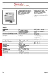
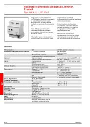
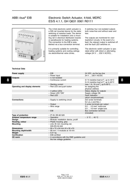
<strong>ABB</strong> i-bus ® <strong>EIB</strong><strong>Electronic</strong> <strong>Switch</strong> <strong>Actuator</strong>, 4-<strong>fold</strong>, <strong>MDRC</strong><strong>ES</strong>/S <strong>4.1.1</strong>, GH Q631 0061 R0111Heat <strong>Switch</strong> Flush Forced Position/1Selection in ETS2– <strong>ABB</strong>OutputBinary output, 4-<strong>fold</strong>The application program enables thefour non-isolated outputs of the electronicswitch actuator to be used tocontrol heating systems and/or coolingceilings via electrothermal valve drives.HeatIn the basic configuration, the applicationhas four 1 bit communication objectsfor switching the outputs. Theelectronic switch actuator can be controlledwith 1 bit control values via twostepor PWM control (PWM=PulseWidth Modulation). To do so, the switchobjects of the outputs must be linkedwith the control value outputs of roomthermostats. The parameters of theroom thermostat must be set to “continuous2-step control” or “switching 2-step control”.If a room thermostat can only transmit8 81 byte control values, it is possible toassign 1 byte objects to the outputs ofthe switch actuator. In this case, theoutputs of the switch actuator can becontrolled via these objects with a 1byte control value.The function of 1 byte control is requiredif the room temperature controlleris only able to send continuous controlvalues or if a continuous control valueis required for other functions (such ascentral inlet temperature control).Otherwise, the control should be carriedout with a 1 bit value.Electrothermal valve drives can becontrolled with the electronic switchactuator. With the parameter “Connectedvalve drive”, the switch actuator isadapted to the characteristic of the valvedrive - “de-energised closed” or “deenergisedopen”. The valve type of thedrive is taken from the technical dataof the respective valve manufacturer.In the event of an overload/short circuitof one or more outputs, the relevantoutput is switched off and the “Fault”LED is switched on.The restart of the output(s) or the extinguishingof the “Fault” LED is onlycarried out once the fault has beenrectified and further ON telegramshave been received at all the previouslyoverloaded outputs.Depending on the type of thermostatcontrol used, the parameter “Controlsignal is received as” must be set to “1bit signal” or “1 byte signal”.The additional parameter “PWM cycletime” appears if 1 byte control hasbeen selected. The cyclic period for theclosing and opening operations of theoutput is set with this parameter. Thereason for cyclical switching lies in thefact that the electronic switch actuatorconverts the 1 byte control value intoan equivalent pulse width modulation.This means for example that at a controlvalue of 66% and a cyclic intervalof 15 minutes, the output opens for 10minutes and closes for 5 minutes.When parameterising the cyclic intervals,it should be noted that it is onlyadvisable to set shorter periods for testpurposes. Even a thermoelectric valvedrive that opens relatively quicklyneeds approx. 2 min to carry out a fullopening and closing operation.FlushIf an output should not be modified e.g.for a week, it can be opened for a settime and then closed again. Thisfunction prevents the heating valvesfrom calcifying during the summer. Thisperiod is set with the parameter “Timercontrolled flushing of the valve”. Thiscan be carried out once per week oronce per month.Alternatively, it is possible to flush thevalves e.g. using a time switch. To doso, the 1 bit object “Valve flushing”must be activated for the respectiveinputs via the parameter “Enable valveflushing by telegram”.The status objects of the outputs arenot updated during flushing.<strong>ES</strong>/S <strong>4.1.1</strong>Page 3 of 6<strong>ES</strong>S_411_TD_EN_V1-12CDC 508 013 D0201<strong>ES</strong>/S <strong>4.1.1</strong>
<strong>ABB</strong> i-bus ® <strong>EIB</strong><strong>Electronic</strong> <strong>Switch</strong> <strong>Actuator</strong>, 4-<strong>fold</strong>, <strong>MDRC</strong><strong>ES</strong>/S <strong>4.1.1</strong>, GH Q631 0061 R0111Bus voltage recoveryThe output of the actuator is an electronicoutput. The output is thereforeopen, provided that the bus voltagehas not been applied. It is not possibleto set a “Default position on bus voltagefailure” in the same way as a relaycontact.It is possible to set the behaviour onbus voltage recovery. The “Position ofthe valve drive in case of bus voltagerecovery” can be set in 10% intervalsbetween 0% = fully closed/open and100% = fully opened/closed.Communication objectsfor 1 bit switch inputs8 8Communication objectsfor continuous control with value inputs(1 byte)No. Type Object name Function0 1 bit Output A <strong>Switch</strong>1 1 bit Output B <strong>Switch</strong>2 1 bit Output C <strong>Switch</strong>3 1 bit Output D <strong>Switch</strong>No. Type Object name Function0 1 byte Output A <strong>Switch</strong>-PWM1 1 byte Output B <strong>Switch</strong>-PWM2 1 byte Output C <strong>Switch</strong>-PWM3 1 byte Output D <strong>Switch</strong>-PWMCommunication objectsfor activated forced positionNo. Type Object name Function…4 1 bit Output A Forced position5 1 bit Output B Forced position6 1 bit Output C Forced position7 1 bit Output D Forced positionCommunication objectswith isolated flushing objectsNo. Type Object name Function…8 1 bit Output A Valve flushing9 1 bit Output B Valve flushing10 1 bit Output C Valve flushing11 1 bit Output D Valve flushingCommunication objectsfor activated fault signalNo. Type Object name Function…12 1 bit Output A Telegr. Fault13 1 bit Output B Telegr. Fault14 1 bit Output C Telegr. Fault15 1 bit Output D Telegr. FaultCommunication objectswith status objectsNo. Type Object name Function…16 1 bit Output A Telegr. Status17 1 bit Output B Telegr. Status18 1 bit Output C Telegr. Status19 1 bit Output D Telegr. Status<strong>ES</strong>/S <strong>4.1.1</strong>Page 5 of 6<strong>ES</strong>S_411_TD_EN_V1-12CDC 508 013 D0201<strong>ES</strong>/S <strong>4.1.1</strong>
<strong>ABB</strong> i-bus ® <strong>EIB</strong><strong>Electronic</strong> <strong>Switch</strong> <strong>Actuator</strong>, 4-<strong>fold</strong>, <strong>MDRC</strong><strong>ES</strong>/S <strong>4.1.1</strong>, GH Q631 0061 R0111ParametersThe default setting for the values isprinted in bold type.Separate for each output:– Control signal is received as 1 bit signal1 byte signal (converted into PWM)Only for 1 byte control:– PWM cycle time 16.5 s / 33 s / 66 s / 2.1 min / 4.4 min /8.9 min / 17.8 min / 36 min / 1.2 h /2.3 h / 4.6 h / 9.5 h / 19 h / 1.6 d /3.1 d / 6.3 d– Connected valve drive de-energised closedde-energised open– Send status of the output yes / no– Enable valve flushing by yes / notelegram– Timer controlled flushing of the valve one time per weekone time per monthno automatic flushingOnly for timer-controlled flushing:– Duration of flushing 4 min6 min10 min– Position of the valve drive in case 0 %of bus voltage recovery 10 %20 %8…890 %100 %Only for 1 bit control:– PWM cycle time for forced position 16.5 s / 33 s / 66 s / 2.1 min / 4.4 min /and failure of room thermostat 8.9 min / 17.8 min / 36 min / 1.2 h /2.3 h / 4.6 h / 9.5 h / 19 h / 1.6 d /3.1 d / 6.3 d– Enable forced position of the valve drive yes / noby EIS1 telegram (1 bit)Only if “yes” is selected:– Position of the valve drive in case 0 %of forced position 10 %20 %…90 %100 %– Cyclical monitoring of the connection yes / noto the room thermostatOnly if “yes” is selected:– Time base for monitoring time 130 ms / 260 ms / 520 ms / 1.0 s /2.1 s / 4.2 s / 8.4 s / 17 s / 34 s /1.1 min / 2.2 min / 4.5 min / 9 min /18 min / 35 min / 1.2 h– Factor for monitoring time (5…127) 107– Position of the valve drive in case of 0 %room thermostat failure 10 %20 %…90 %100 %<strong>ES</strong>/S <strong>4.1.1</strong>Page 6 of 6<strong>ES</strong>S_411_TD_EN_V1-12CDC 508 013 D0201<strong>ES</strong>/S <strong>4.1.1</strong>