SSI Series - Sensortechnics
SSI Series - Sensortechnics
SSI Series - Sensortechnics

You also want an ePaper? Increase the reach of your titles
YUMPU automatically turns print PDFs into web optimized ePapers that Google loves.
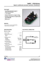
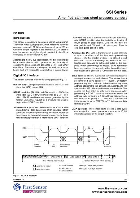
<strong>SSI</strong> <strong>Series</strong>Amplified stainless steel pressure sensorsI²C BUSIntroductionThe sensor is capable to generate a digital output signal.The device runs a cyclic program, which will store a correctedpressure value with 13 bit resolution about every 500 µswithin the output registers of the internal ASIC. In order touse the sensor for digital signal readout, it should beconnected to a bidirectional I²C-bus.According to the I²C-bus specification, the bus is controlledby a master device, which generates the clock signal,controls the bus access and generates START and STOPconditions. The sensor is designed to work as a slave,hence it will only respond to requests from a master device.Digital I²C interfaceThe sensor complies with the following protocol (Fig. 1):Bus not busy: During idle periods both data line (SDA) andclock line (SCL) remain HIGH.START condition (S): HIGH to LOW transition of SDA linewhile clock (SCL) is HIGH is interpreted as START condition.START conditions are always generated by themaster. Each initial request for a pressure value has tobegin with a START condition.STOP condition (P): LOW to HIGH transition of SDA line whileclock (SCL) is HIGH determines STOP condition. STOPconditions are always generated by the master. More thanone request for the current pressure value can be transmittedwithout generation of intermediate STOP condition.DATA valid (D): State of data line represents valid data when,after START condition, data line is stable for duration ofHIGH period of clock signal. Data on line must bechanged during LOW period of clock signal. There isone clock pulse per bit of data.Acknowledge (A): Data is transferred in pieces of 8 bits(1 byte) on serial bus, MSB first. After each byte receivingdevice – whether master or slave – is obliged to pulldata line LOW as acknowledge for reception of data.Master must generate an extra clock pulse for this purpose.When acknowledge is missed, slave transmitterbecomes inactive. It is on master either to send last commandagain or to generate STOP condition in that case.Slave address: The I²C-bus master-slave concept requiresa unique address for each device. The sensor has apreconfigured slave address (1111000xb). By factoryprogramming it is possible to define a secondary slaveaddress additional to the general one. According to I²Cspecification 127 different addresses are available. Thesensor will then listen to both slave addresses. Aftergenerating a START condition the master sends theaddress byte containing a 7 bit address followed by adata direction bit (R/W). A "0" indicates a transmissionfrom master to slave (WRITE), a "1" indicates a datarequest (READ).DATA operation: The sensor starts to send 2 data bytescontaining the current pressure value as a 15 bitinformation placed in the output registers.SCLSDASTARTconditionDatavalidData allowedto changeSTOPcondition1S Slave Address R/W A Data Byte 1 A Data Byte 2AData Byte 1PRead out of first pressure valueRead out of n pressure values (optional)generated by mastergenerated by slaveS = START conditionA = AcknowledgeP = STOP conditionData Byte 1 = High Byte (MSB first)Data Byte 2 = Low Byte (LSB last)Fig. 1:I²C bus protocolE / 11671 / D3/7www.first-sensor.comwww.sensortechnics.com