SSI Series - Sensortechnics
SSI Series - Sensortechnics
SSI Series - Sensortechnics

Create successful ePaper yourself
Turn your PDF publications into a flip-book with our unique Google optimized e-Paper software.
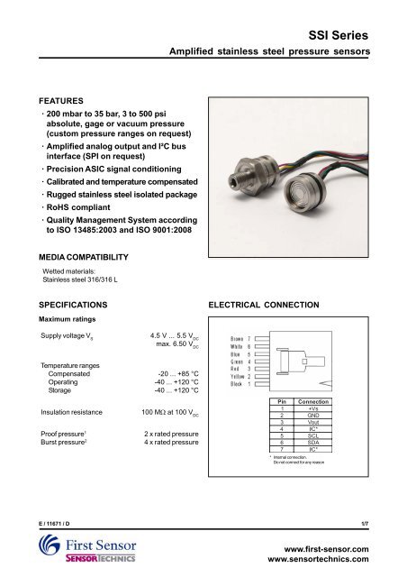
<strong>SSI</strong> <strong>Series</strong>Amplified stainless steel pressure sensorsI²C BUSIntroductionThe sensor is capable to generate a digital output signal.The device runs a cyclic program, which will store a correctedpressure value with 13 bit resolution about every 500 µswithin the output registers of the internal ASIC. In order touse the sensor for digital signal readout, it should beconnected to a bidirectional I²C-bus.According to the I²C-bus specification, the bus is controlledby a master device, which generates the clock signal,controls the bus access and generates START and STOPconditions. The sensor is designed to work as a slave,hence it will only respond to requests from a master device.Digital I²C interfaceThe sensor complies with the following protocol (Fig. 1):Bus not busy: During idle periods both data line (SDA) andclock line (SCL) remain HIGH.START condition (S): HIGH to LOW transition of SDA linewhile clock (SCL) is HIGH is interpreted as START condition.START conditions are always generated by themaster. Each initial request for a pressure value has tobegin with a START condition.STOP condition (P): LOW to HIGH transition of SDA line whileclock (SCL) is HIGH determines STOP condition. STOPconditions are always generated by the master. More thanone request for the current pressure value can be transmittedwithout generation of intermediate STOP condition.DATA valid (D): State of data line represents valid data when,after START condition, data line is stable for duration ofHIGH period of clock signal. Data on line must bechanged during LOW period of clock signal. There isone clock pulse per bit of data.Acknowledge (A): Data is transferred in pieces of 8 bits(1 byte) on serial bus, MSB first. After each byte receivingdevice – whether master or slave – is obliged to pulldata line LOW as acknowledge for reception of data.Master must generate an extra clock pulse for this purpose.When acknowledge is missed, slave transmitterbecomes inactive. It is on master either to send last commandagain or to generate STOP condition in that case.Slave address: The I²C-bus master-slave concept requiresa unique address for each device. The sensor has apreconfigured slave address (1111000xb). By factoryprogramming it is possible to define a secondary slaveaddress additional to the general one. According to I²Cspecification 127 different addresses are available. Thesensor will then listen to both slave addresses. Aftergenerating a START condition the master sends theaddress byte containing a 7 bit address followed by adata direction bit (R/W). A "0" indicates a transmissionfrom master to slave (WRITE), a "1" indicates a datarequest (READ).DATA operation: The sensor starts to send 2 data bytescontaining the current pressure value as a 15 bitinformation placed in the output registers.SCLSDASTARTconditionDatavalidData allowedto changeSTOPcondition1S Slave Address R/W A Data Byte 1 A Data Byte 2AData Byte 1PRead out of first pressure valueRead out of n pressure values (optional)generated by mastergenerated by slaveS = START conditionA = AcknowledgeP = STOP conditionData Byte 1 = High Byte (MSB first)Data Byte 2 = Low Byte (LSB last)Fig. 1:I²C bus protocolE / 11671 / D3/7www.first-sensor.comwww.sensortechnics.com
<strong>SSI</strong> <strong>Series</strong>Amplified stainless steel pressure sensorsPHYSICAL DIMENSIONS<strong>SSI</strong>...1 (weld ring)Vent tubeWires, 100 mmØ 16.45.0Ø 1.6O-ring grooverecommended size 15.6 x 1.7813.05.52.43.0Do not touch diaphragm!Ø 15.0Ø 18.4Ø 19.0-0,05 mmmass: approx. 17 g dimensions in mm+0,00 mmA clearance fit 19H8 with 20 ° phase is recommended for mounting.<strong>SSI</strong>...5 (1/4 " NPT)Vent tubeØ 19.0Wires, 100 mmØ 1.65.028.50SW 2010.0R16.0Ø 4.4mass: approx. 50 g 1/4 NPTdimensions in mmE / 11671 / D5/7www.first-sensor.comwww.sensortechnics.com
<strong>SSI</strong> <strong>Series</strong>Amplified stainless steel pressure sensorsPHYSICAL DIMENSIONS<strong>SSI</strong>...9 (G 1/8 " HEX)Vent tubeØ 19.0Wires, 100 mmØ 1.65.028.56.0SW 2010.0O-ring grooverecommended size 11x2Ø 4.4mass: approx. 35 g G 1/8dimensions in mmOPTIONAL PRESSURE FITTING<strong>SSI</strong>...N(1/4 " NPT fitting for G 1/8 " thread)1/4 NPT11.518SW 14G 1/8Other fittings are available on request. Please contact First Sensor.E / 11671 / D6/7www.first-sensor.comwww.sensortechnics.com
<strong>SSI</strong> <strong>Series</strong>Amplified stainless steel pressure sensorsORDERING INFORMATIONOptionsExample:<strong>Series</strong><strong>SSI</strong>M200Pressure rangeM700B001B3x5B010B020B035P003P010P015P050P150P300P500200mbarA*Pressuremode700mbarG G ageV*CalibrationHousingElectricalconnectionAbsoluteU Unidirectional 1 WeldringA AMP-V acuum*5 1/4" NPT1 bar9 G 1/8" HEX3 .5 barN**10 bar20 bar35 bar3 psi10 psi15 psi50 psi150 psi300 psi500 psi* only availablefrom700 mbar.MOQ may apply* only available as<strong>SSI</strong>M200GV...(0...-200 mbar)1/4" NPTfitting* MOQ may apply**1/4" NPT fitting onG 1/8" threadMODU**TYCO5-103956-6GradeHSupplyHigh5 5 V<strong>SSI</strong>B001G U 9 A H 5Custom pressure ranges, higher accuracy, SPI bus interface, 3 V supply and other pressurefittings are available on request. MOQ may apply. Please contact First Sensor.First Sensor reserves the right to make changes to any products herein.First Sensor does not assume any liability arising out of the applicationor use of any product or circuit described herein, neither does it conveyany license under its patent rights nor the rights of others.E / 11671 / D7/7www.first-sensor.comwww.sensortechnics.com