Tutorial 2: Drawing Setup in AutoCAD 2010
Tutorial 2: Drawing Setup in AutoCAD 2010
Tutorial 2: Drawing Setup in AutoCAD 2010

Create successful ePaper yourself
Turn your PDF publications into a flip-book with our unique Google optimized e-Paper software.
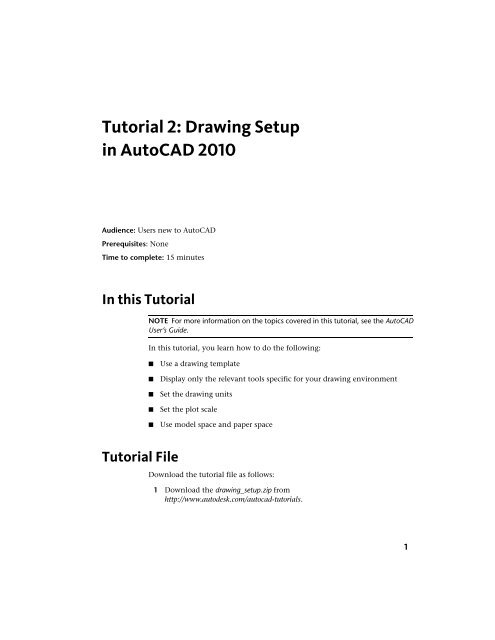
<strong>Tutorial</strong> 2: <strong>Draw<strong>in</strong>g</strong> <strong>Setup</strong><strong>in</strong> <strong>AutoCAD</strong> <strong>2010</strong>1Audience: Users new to <strong>AutoCAD</strong>Prerequisites: NoneTime to complete: 15 m<strong>in</strong>utesIn this <strong>Tutorial</strong>NOTE For more <strong>in</strong>formation on the topics covered <strong>in</strong> this tutorial, see the <strong>AutoCAD</strong>User’s Guide.In this tutorial, you learn how to do the follow<strong>in</strong>g:■■■■■Use a draw<strong>in</strong>g templateDisplay only the relevant tools specific for your draw<strong>in</strong>g environmentSet the draw<strong>in</strong>g unitsSet the plot scaleUse model space and paper space<strong>Tutorial</strong> FileDownload the tutorial file as follows:1 Download the draw<strong>in</strong>g_setup.zip fromhttp://www.autodesk.com/autocad-tutorials.1
2 Unzip draw<strong>in</strong>g_setup.zip to C:\My Documents\<strong>Tutorial</strong>s.Lesson 1: Use a <strong>Draw<strong>in</strong>g</strong> TemplateIn this lesson, you learn how to start a draw<strong>in</strong>g us<strong>in</strong>g a draw<strong>in</strong>g template file.When you use a template file, new draw<strong>in</strong>gs created from the templateautomatically use the sett<strong>in</strong>gs def<strong>in</strong>ed <strong>in</strong> the template. This saves you setuptime and helps to make sure each draw<strong>in</strong>g you create follows your company’sCAD standards.<strong>Draw<strong>in</strong>g</strong> template files have a .dwt file extensionSome of the sett<strong>in</strong>gs stored <strong>in</strong> draw<strong>in</strong>g template files <strong>in</strong>clude■Unit type and scale (precision)■■■■■■Title blocks/borders, blocks, and logosLayer namesSnap, grid, and ortho sett<strong>in</strong>gsGrid limitsAnnotation stylesL<strong>in</strong>etypesTo start a draw<strong>in</strong>g with a template1 Click Start menu (W<strong>in</strong>dows) ➤ (All) Programs ➤ Autodesk ➤ <strong>AutoCAD</strong><strong>2010</strong> ➤ <strong>AutoCAD</strong> <strong>2010</strong> - English.2 NOTE If the New Features dialog box appears, select Maybe later and OKto close it.The <strong>AutoCAD</strong> w<strong>in</strong>dow opens with an empty draw<strong>in</strong>g file <strong>Draw<strong>in</strong>g</strong>1.dwg.3 Click ➤ New.2 | <strong>Tutorial</strong> 2: <strong>Draw<strong>in</strong>g</strong> <strong>Setup</strong> <strong>in</strong> <strong>AutoCAD</strong> <strong>2010</strong>
4 In the Select Template dialog box, select <strong>Tutorial</strong>-iArch.dwt.5 Click Open to open the <strong>Tutorial</strong>-iArch.dwt template.Lesson 1: Use a <strong>Draw<strong>in</strong>g</strong> Template | 3
Notice that the file name is <strong>Draw<strong>in</strong>g</strong>2.dwg. You are not open<strong>in</strong>g the<strong>Tutorial</strong>-iArch.dwt file template file, but are open<strong>in</strong>g a new draw<strong>in</strong>g basedon the template file.The <strong>Tutorial</strong>-iArch.dwt template file is used for architectural draw<strong>in</strong>gs, and<strong>in</strong>cludes predef<strong>in</strong>ed sett<strong>in</strong>gs for draw<strong>in</strong>g units, dimension style, l<strong>in</strong>etype,layer, border and title block.When you use a template file, you can start your draw<strong>in</strong>g immediatelywithout hav<strong>in</strong>g to spend time def<strong>in</strong><strong>in</strong>g sett<strong>in</strong>gs and styles.6 Click ➤ Close ➤ Current <strong>Draw<strong>in</strong>g</strong> to close <strong>Draw<strong>in</strong>g</strong>2.dwg.Lesson 2: Switch WorkspacesThe workspace is the <strong>AutoCAD</strong> w<strong>in</strong>dow layout of dockable w<strong>in</strong>dows, menus,toolbars, and other user <strong>in</strong>terface features. You can select a predef<strong>in</strong>edworkspace or def<strong>in</strong>e your own. In this lesson, you learn how to select thepredef<strong>in</strong>ed workspaces, <strong>in</strong>clud<strong>in</strong>g the workspace for creat<strong>in</strong>g a 3D model.When you use a workspace, only the menus, toolbars, ribbon tabs, and palettesrelevant to a task are displayed.4 | <strong>Tutorial</strong> 2: <strong>Draw<strong>in</strong>g</strong> <strong>Setup</strong> <strong>in</strong> <strong>AutoCAD</strong> <strong>2010</strong>
To switch workspaces1 The status bar is located at the bottom of the w<strong>in</strong>dow. The Workspacesicon on the status bar is shown below.NOTE If you do not see this icon, right-click <strong>in</strong> an empty area on the statusbar and click Workspaces. If you still do not see this icon, you may need tomaximize the <strong>AutoCAD</strong> w<strong>in</strong>dow.2 Click the down arrow to display the menu of predef<strong>in</strong>ed workspaces.3 On the Workspace menu, click 3D Model<strong>in</strong>g.4 The 3D Model<strong>in</strong>g workspace is displayed. The Workspaces icon <strong>in</strong> thestatus bar <strong>in</strong>dicates that you are now <strong>in</strong> the 3D Model<strong>in</strong>g workspace. Inthis workspace, you can access the various commands and tools neededfor creat<strong>in</strong>g 3D draw<strong>in</strong>gs. For example, notice the 3D model<strong>in</strong>g commandsavailable <strong>in</strong> the ribbon.NOTE The selected workspace is reta<strong>in</strong>ed when you close and reopen<strong>AutoCAD</strong>. To return to 2D Draft<strong>in</strong>g & Annotation, you must select it.Lesson 2: Switch Workspaces | 5
5 To access help <strong>in</strong>formation for the Ribbon commands, place the mousecursor over one of the commands and keep the cursor there for a second.Help <strong>in</strong>formation for the Smooth Object command is shown below.6 | <strong>Tutorial</strong> 2: <strong>Draw<strong>in</strong>g</strong> <strong>Setup</strong> <strong>in</strong> <strong>AutoCAD</strong> <strong>2010</strong>
6 Use the Workspaces icon on the status bar to switch back to the 2DDraft<strong>in</strong>g & Annotation workspace.Lesson 3: Select the <strong>Draw<strong>in</strong>g</strong> UnitsIn this lesson, you learn how to set the draw<strong>in</strong>g unit and the scale for adraw<strong>in</strong>g.Before you start a draw<strong>in</strong>g, you must first decide what draw<strong>in</strong>g units to use.In <strong>AutoCAD</strong>, distances are measured <strong>in</strong> draw<strong>in</strong>g units. In a draw<strong>in</strong>g, onedraw<strong>in</strong>g unit may equal one <strong>in</strong>ch, one millimeter, one meter, or one mile.Before you beg<strong>in</strong> draw<strong>in</strong>g, you decide what one draw<strong>in</strong>g unit will represent.<strong>AutoCAD</strong> does not <strong>in</strong>clude a sett<strong>in</strong>g that determ<strong>in</strong>es the length of a draw<strong>in</strong>gunit.After you decide what draw<strong>in</strong>g units to use, you can set the format of thedraw<strong>in</strong>g units. The format sett<strong>in</strong>gs available for l<strong>in</strong>ear units <strong>in</strong>clude■ Architectural. A length of 15.5 units displays as 1’-3 1/2”■ Decimal. A length of 15.5 units displays as 15.5000■ Eng<strong>in</strong>eer<strong>in</strong>g. A length of 15.5 units displays as 1’-3.5”For example, a mechanical eng<strong>in</strong>eer who works <strong>in</strong> millimeters would set theformat for l<strong>in</strong>ear units to decimal. An architect who works <strong>in</strong> feet and <strong>in</strong>ches,would set the format to architectural.Lesson 3: Select the <strong>Draw<strong>in</strong>g</strong> Units | 7
The draw<strong>in</strong>g unit format controls only the display style of the draw<strong>in</strong>g unitson-screen, such as <strong>in</strong> the display of coord<strong>in</strong>ates and values <strong>in</strong> the dialog boxesand prompts.To set the format of the draw<strong>in</strong>g units1 Click ➤ <strong>Draw<strong>in</strong>g</strong> Utilities ➤ Units.2 In the <strong>Draw<strong>in</strong>g</strong> Units dialog box, under Length, select the follow<strong>in</strong>gvalues:■Type: Architectural■ Precision: 0’-0 1/8’’8 | <strong>Tutorial</strong> 2: <strong>Draw<strong>in</strong>g</strong> <strong>Setup</strong> <strong>in</strong> <strong>AutoCAD</strong> <strong>2010</strong>
The Sample Output section shows the display style of the draw<strong>in</strong>g unitson-screen. Select different length types, such as Decimal, Scientific, orEng<strong>in</strong>eer<strong>in</strong>g and notice how the sample output changes.3 Click Cancel to close the dialog box.Lesson 4: Set the Plot ScaleIn this lesson, you learn to specify a scale to output your draw<strong>in</strong>g.When you plot a draw<strong>in</strong>g, you either specify a precise scale or fit the imagedesign to the current paper size. For example, a distance of one draw<strong>in</strong>g unittypically represents one millimeter or one meter <strong>in</strong> a metric draw<strong>in</strong>g, whileone <strong>in</strong>ch or one foot <strong>in</strong> real-world units are common <strong>in</strong> an imperial draw<strong>in</strong>g.Lesson 4: Set the Plot Scale | 9
To plot us<strong>in</strong>g a custom scale1 Click ➤ Open ➤ <strong>Draw<strong>in</strong>g</strong> and select Architectural - Imperial.dwg <strong>in</strong>the Select File dialog box.2 Verify that the Model tab at the bottom of the draw<strong>in</strong>g w<strong>in</strong>dow is selected.You must be <strong>in</strong> model space for this lesson.3 Click ➤ Pr<strong>in</strong>t ➤ Plot .4 In the Plot dialog box, under Page setup, click Add.10 | <strong>Tutorial</strong> 2: <strong>Draw<strong>in</strong>g</strong> <strong>Setup</strong> <strong>in</strong> <strong>AutoCAD</strong> <strong>2010</strong>
5 In the Add Page <strong>Setup</strong> dialog box, enter My<strong>Setup</strong>. Click OK.6 Under Pr<strong>in</strong>ter/plotter, Name list, select your pr<strong>in</strong>ter to plot the currentlayout.7 Under Plot Scale, select 1:50 from the Scale drop-down list.NOTE If the Fit to paper check box is selected, the Scale list is not available8 Click Preview. If the Plot Scale Confirm dialog box is displayed, clickCont<strong>in</strong>ue. The plot preview of the draw<strong>in</strong>g is displayed at the selectedscale of 1:50.Lesson 4: Set the Plot Scale | 11
9 In the preview w<strong>in</strong>dow, click Plot to pr<strong>in</strong>t the draw<strong>in</strong>g.10 Click to close the preview w<strong>in</strong>dow, and click Cancel to close the Plotdialog box.To scale a draw<strong>in</strong>g to fit the page1 Click ➤ Pr<strong>in</strong>t ➤ Plot.2 In the Plot dialog box, under Plot Scale, select the Fit to Paper check box.12 | <strong>Tutorial</strong> 2: <strong>Draw<strong>in</strong>g</strong> <strong>Setup</strong> <strong>in</strong> <strong>AutoCAD</strong> <strong>2010</strong>
The result<strong>in</strong>g scale is automatically calculated. The ratio of plotted todraw<strong>in</strong>g units <strong>in</strong> the custom scale is displayed.3 Click OK to plot the draw<strong>in</strong>g.TIP To preview the plotted draw<strong>in</strong>g, <strong>in</strong> the Plot dialog box, click Preview.Lesson 5: Understand Model Space and PaperSpaceIn this lesson, you learn some basic concepts about model space and paperspace.There are two dist<strong>in</strong>ct work<strong>in</strong>g environments or “spaces,” <strong>in</strong> which you cancreate objects <strong>in</strong> a draw<strong>in</strong>g, model space and paper space.Use the tabs at the bottom of the draw<strong>in</strong>g area to access model space andpaper space. Use the Model tab for model space, and use one or more of theLayout tabs for paper space.NOTE These tabs can be hidden, appear<strong>in</strong>g <strong>in</strong>stead as buttons on the status bar.In model space, you draw a model of your subject at 1:1 scale. In paper space,you can create one or more layout viewports, dimensions, notes, and a titleblock to represent a draw<strong>in</strong>g sheet.To switch between model space and paper space1 If not already open, click ➤ Open ➤ <strong>Draw<strong>in</strong>g</strong> and select Architectural- Imperial.dwg <strong>in</strong> the Select File dialog box.Lesson 5: Understand Model Space and Paper Space | 13
2 Click the Model tab (if not already selected). In model space, you draw,view, and edit your model.3 Click the Layout1 tab to enter paper space. You can tell you are <strong>in</strong> paperspace, when you see the icon (shown <strong>in</strong> blue below) <strong>in</strong> the lower corner.If you are not <strong>in</strong> paper space, double-click the left mouse button <strong>in</strong> ablank area outside of the rectangle.14 | <strong>Tutorial</strong> 2: <strong>Draw<strong>in</strong>g</strong> <strong>Setup</strong> <strong>in</strong> <strong>AutoCAD</strong> <strong>2010</strong>
4 You can toggle back and forth between paper space and model space. Toenter model space, double-click the left mouse button <strong>in</strong> the middle ofthe rectangle. Notice that the border of the <strong>in</strong>side rectangle becomesthicker and the blue icon <strong>in</strong>dicat<strong>in</strong>g paper space disappears.5 In model space, the area surrounded by the rectangle with the thickborder is the layout viewport. You can use layout viewports to accessmodel space from with<strong>in</strong> paper space. A layout viewport is like a pictureframe conta<strong>in</strong><strong>in</strong>g a “photograph” of the model <strong>in</strong> model space.6 Practice toggl<strong>in</strong>g back and forth between model space and paper spaceby double-click<strong>in</strong>g the left mouse button <strong>in</strong>side the viewport (to entermodel space) and outside <strong>in</strong> the blank area (to enter paper space).NOTE If you are hav<strong>in</strong>g trouble enter<strong>in</strong>g model space, click the word PAPERfrom the status bar to switch to MODEL.To set a viewport to a specific scale1 Ensure that you have Architectural - Imperial.dwg open.2 Click the Layout1 tab to the right of the Model tab. Make sure you are<strong>in</strong> paper space.Lesson 5: Understand Model Space and Paper Space | 15
3 Click the border of the viewport.4 Right-click, and then click Properties.5 In the Properties palette, select Standard Scale, and then select 3/8” =1’-0” from the list.16 | <strong>Tutorial</strong> 2: <strong>Draw<strong>in</strong>g</strong> <strong>Setup</strong> <strong>in</strong> <strong>AutoCAD</strong> <strong>2010</strong>
The selected scale is applied to the viewport.Lesson 5: Understand Model Space and Paper Space | 17