Word Pro - MIW2000 - LR Informática Industrial
Word Pro - MIW2000 - LR Informática Industrial
Word Pro - MIW2000 - LR Informática Industrial

Create successful ePaper yourself
Turn your PDF publications into a flip-book with our unique Google optimized e-Paper software.
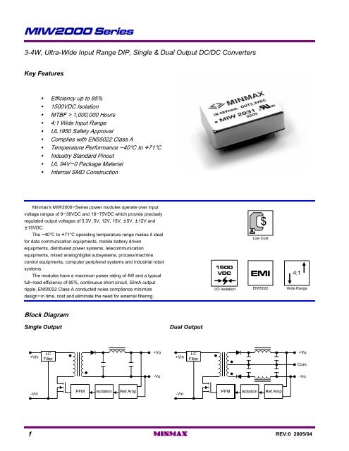
<strong>MIW2000</strong> Series3-4W, Ultra-Wide Input Range DIP, Single & Dual Output DC/DC ConvertersKey Features• Efficiency up to 85%• 1500VDC Isolation• MTBF > 1,000,000 Hours• 4:1 Wide Input Range• UL1950 Safety Approval• Complies with EN55022 Class A• Temperature Performance -40] to +71]• Industry Standard Pinout• UL 94V-0 Package Material• Internal SMD ConstructionMinmax's <strong>MIW2000</strong>-Series power modules operate over inputvoltage ranges of 9-36VDC and 18-75VDC which provide preciselyregulated output voltages of 3.3V, 5V, 12V, 15V, {5V, {12V and{15VDC.The -40] to +71] operating temperature range makes it idealfor data communication equipments, mobile battery drivenequipments, distributed power systems, telecommunicationequipments, mixed analog/digital subsystems, process/machinecontrol equipments, computer peripheral systems and industrial robotsystems.The modules have a maximum power rating of 4W and a typicalfull-load efficiency of 85%, continuous short circuit, 50mA outputripple, EN55022 Class A conducted noise compliance minimizedesign-in time, cost and eliminate the need for external filtering.1500VDCI/O Isolation$Low CostEMIEN550224:1Wide RangeBlock DiagramSingle OutputDual Output+VinLCFilter+Vo+VinLCFilter+VoCom.-Vo-Vo-VinPFM Isolation Ref.Amp-VinPFM Isolation Ref.Amp1MINMAXREV:0 2005/04
<strong>MIW2000</strong> SeriesModel Selection GuideModelNumberInputVoltageOutputVoltageOutput CurrentInput CurrentReflectedRippleCurrentEfficiencyMax.Min.@Max. Load@No Load@Max. LoadVDCVDCmAmAmA (Typ.)mA (Typ.)mA (Typ.)% (Typ.)MIW20213.39009016177MIW202256606617081MIW2023MIW2024MIW202524( 9 ~ 36 )1215{5333267{3003327{30201201156205838380MIW2026{12{167{1720183MIW2027{15{133{1320183MIW20313.3900907978MIW20325660668482MIW2033MIW2034MIW203548( 18 ~ 75 )1215{5333267{3003327{30989876105858582MIW2036{12{167{179885MIW2037{15{133{139885Absolute Maximum RatingsInput Surge Voltage( 1000 mS )ParameterLead Temperature (1.5mm from case for 10 Sec.)Internal Power Dissipation24VDC Input Models48VDC Input ModelsMin.-0.7-0.7------Max.1002602,500Exceeding the absolute maximum ratings of the unit could cause damage.These are not continuous operating ratings.50UnitVDCVDC]mWNotes :1. Specifications typical at Ta=+25], resistive load,nominal input voltage, rated output current unlessotherwise noted.2. Transient recovery time is measured to within 1%error band for a step change in output load of 75%to 100%.3. Ripple & Noise measurement bandwidth is 0-20MHz.Environmental SpecificationsParameterConditions Min. Max.Operating TemperatureAmbient -40 +71Operating TemperatureCase-40 +90Storage Temperature-40 +125Humidity--- 95CoolingFree-Air ConvectionConducted EMIEN55022 Class AUnit]]]%4. These power converters require a minimum outputloading to maintain specified regulation.5. Operation under no-load conditions will notdamage these modules; however, they may notmeet all specifications listed.6. All DC/DC converters should be externally fused atthe front end for protection.7. Other input and output voltage may be available,please contact factory.8. Specifications subject to change without notice.REV:0 2005/04MINMAX2
<strong>MIW2000</strong> SeriesInput SpecificationsParameterStart VoltageUnder Voltage ShutdownReverse Polarity Input CurrentShort Circuit Input PowerInput FilterModel24V Input Models48V Input Models24V Input Models48V Input ModelsAll ModelsMin.4.58.5------------Typ. Max.68.51217---8--- 16---1--- 2000Pi FilterUnitVDCAmWOutput SpecificationsParameterOutput Voltage AccuracyOutput Voltage BalanceLine RegulationLoad RegulationRipple & Noise (20MHz)Ripple & Noise (20MHz)Ripple & Noise (20MHz)Over Power <strong>Pro</strong>tectionTransient Recovery TimeTransient Response DeviationTemperature CoefficientOutput Short CircuitConditionsDual Output, Balanced LoadsVin=Min. to Max.Io=10% to 100%Over Line, Load & Temp.25% Load Step ChangeMin.---------------------120---------ContinuousTyp.{0.5{0.5{0.2{0.350---------150{2{0.01Max.{1.0{2.0{0.5{1.07510015---500---{0.02Unit%%%%mV P-PmV P-PmV rms%uS%%/]General SpecificationsParameterIsolation Voltage RatedIsolation Voltage TestIsolation ResistanceIsolation CapacitanceSwitching FrequencyMTBFConditions60 SecondsFlash Tested for 1 Second500VDC100KHz,1VMIL-HDBK-217F @ 25], Ground BenignMin.150016501000------1000Typ.---------380350---Max.---------500------UnitVDCVDCM[pFKHzK HoursCapacitive LoadModels by VoutMaximum Capacitive Load# For each output3.3V30005V300012V300015V3000{5V #680{12V #680{15V #680UnituF3MINMAXREV:0 2005/04
<strong>MIW2000</strong> SeriesInput Fuse Selection Guide24V Input Models1000mA Slow - Blow Type48V Input Models500mA Slow - Blow TypeInput Voltage Transient RatingVin ( VDC )150140130120110100908070605040302010010uS48VDC Input Models24VDC Input Models100uS 1mS 10mS 100mSREV:0 2005/04MINMAX4
<strong>MIW2000</strong> Series1001009090Efficiency (%)8070Efficiency (%)8070606050LowNomHigh50LowNomHighInput Voltage (V)Input Voltage (V)Efficiency vs Input Voltage ( Single Output )Efficiency vs Input Voltage ( Dual Output )90908080Efficiency (%)706050Efficiency (%)706050404030302010 20 40 60 801002010 20 40 60 80100Load Current (%)Load Current (%)Efficiency vs Output Load ( Single Output )Efficiency vs Output Load ( Dual Output )10080100LFM400LFMOutput Power (%)6040Naturalconvection200LFM200〜-40 50 60 70 80 90 100 110Ambient Temperature]Derating Curve5MINMAXREV:0 2005/04
<strong>MIW2000</strong> SeriesTest ConfigurationsInput Reflected-Ripple Current Test SetupInput reflected-ripple current is measured with a inductorLin (4.7uH) and Cin (220uF, ESR < 1.0[ at 100 KHz) tosimulate source impedance.Capacitor Cin, offsets possible battery impedance.Current ripple is measured at the input terminals of themodule, measurement bandwidth is 0-500 KHz.Overcurrent <strong>Pro</strong>tectionTo provide protection in a fault (output overload) condition,the unit is equipped with internal current limiting circuitry andcan endure current limiting for an unlimited duration. At thepoint of current-limit inception, the unit shifts from voltagecontrol to current control. The unit operates normally once theoutput current is brought back into its specified range.Input Source ImpedanceTo Oscilloscope+ + LinBatteryCinCurrent<strong>Pro</strong>be+Vin+OutDC / DCConverter-Vin-OutLoadThe power module should be connected to a lowac-impedance input source. Highly inductive sourceimpedances can affect the stability of the power module.In applications where power is supplied over long lines andoutput loading is high, it may be necessary to use a capacitorat the input to ensure startup.Peak-to-Peak Output Noise Measurement TestUse a Cout 0.47uF ceramic capacitor.Scope measurement should be made by using a BNCsocket, measurement bandwidth is 0-20 MHz. Position theload between 50 mm and 75 mm from the DC/DC Converter.+VinSingle OutputDC / DCConverter+OutCopper StripCoutScopeResistiveLoadCapacitor mounted close to the power module helpsensure stability of the unit, it is recommended to use a goodquality low Equivalent Series Resistance (ESR < 1.0[ at 100KHz) capacitor of a 4.7uF for the 24V input devices and a2.2uF for the 48V devices.+DC PowerSource-+Cin+Vin-VinDC / DCConverter+Out-OutLoad-Vin-OutOutput Ripple Reduction+VinDual OutputDC / DCConverter-Vin+OutCom.-OutCopper StripCoutCoutDesign & Feature ConsiderationsScopeResistiveLoadScopeA good quality low ESR capacitor placed as close aspracticable across the load will give the best ripple and noiseperformance.To reduce output ripple, it is recommended to use 3.3uFcapacitors at the output.+DC PowerSource-+Vin-VinSingle OutputDC / DCConverter+Out-OutCoutLoadMaximum Capacitive LoadThe <strong>MIW2000</strong> series has limitation of maximum connectedcapacitance at the output.The power module may be operated in current limitingmode during start-up, affecting the ramp-up and the startuptime.For optimum performance we recommend 680uFmaximum capacitive load for dual outputs and 3000uFcapacitive load for single outputs.The maximum capacitance can be found in the data sheet.+DC PowerSource-+Vin-VinDual OutputDC / DCConverter+OutCom.-OutCoutLoadREV:0 2005/04MINMAX6
<strong>MIW2000</strong> SeriesThermal ConsiderationsMany conditions affect the thermal performance of thepower module, such as orientation, airflow over the moduleand board spacing. To avoid exceeding the maximumtemperature rating of the components inside the powermodule, the case temperature must be kept below 90°C.The derating curves are determined from measurementsobtained in an experimental apparatus.Position of air velocityprobe and thermocouple15mm / 0.6in50mm / 2inAir FlowDUT7MINMAXREV:0 2005/04
<strong>MIW2000</strong> SeriesMechanical DimensionsConnecting Pin PatternsTop View ( 2.54 mm / 0.1 inch grids )Single Output31.8 [1.25]4.1 [0.16]Side10.2 [0.40]2.54 [0.100]Bottom4.5 [0.18]2 3 9 1123 220.50 [0.020]16 1415.22 [0.600] 2.5 [0.10]20.3 [0.80]Dual OutputTolerancePinMillimetersX.X{0.25X.XX{0.13{0.05InchesX.XX{0.01X.XXX{0.005{0.002Pin ConnectionsPhysical CharacteristicsPin2Single Output-VinDual Output-VinCase Size31.8*20.3*10.2 mm:1.25*0.80*0.40 inches3-Vin-Vin911No PinNCCommon-VoutCase Material: Metal With Non-Conductive Baseplate1416+Vout-Vout+VoutCommonWeight: 16.2g22+Vin+VinFlammability: UL94V-023+Vin+VinNC: No ConnectionThe <strong>MIW2000</strong> converter is encapsulated in a low thermal resistance molding compound that has excellent resistance/electricalcharacteristics over a wide temperature range or in high humidity environments.The encapsulant and unit case are both rated to UL 94V-0 flammability specifications.Leads are tin plated for improved solderability.REV:0 2005/04MINMAX8