The Secrets of RS-485 Half-duplex Communication - Moxa
The Secrets of RS-485 Half-duplex Communication - Moxa
The Secrets of RS-485 Half-duplex Communication - Moxa

Create successful ePaper yourself
Turn your PDF publications into a flip-book with our unique Google optimized e-Paper software.
<strong>Moxa</strong> Tech Note<br />
<strong>The</strong> <strong>Secrets</strong> <strong>of</strong> <strong>RS</strong>-<strong>485</strong> <strong>Half</strong>-<strong>duplex</strong> <strong>Communication</strong><br />
Copyright © 2009 <strong>Moxa</strong> Inc. Released on Sep 28, 2009<br />
About <strong>Moxa</strong><br />
<strong>Moxa</strong> manufactures one <strong>of</strong> the world’s leading brands <strong>of</strong> device networking solutions. Products include serial<br />
boards, USB-to-serial hubs, media converters, device servers, embedded computers, Ethernet I/O servers,<br />
terminal servers, Modbus gateways, industrial switches, and Ethernet-to-fiber converters. Our products are key<br />
components <strong>of</strong> many networking applications, including industrial automation, manufacturing, POS, and medical<br />
treatment facilities.<br />
How to Contact <strong>Moxa</strong><br />
Tel: 1-714-528-6777<br />
Fax: 1-714-528-6778<br />
Web: www.moxa.com<br />
Email: info@moxa.com<br />
Casper Yang, Senior Product Manager<br />
support@moxa.com<br />
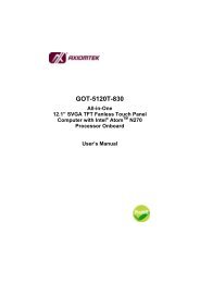
<strong>RS</strong>-<strong>485</strong> is a good choice for long distance serial communication since using<br />
differential transmission cancels out the vast majority <strong>of</strong> electromagnetic<br />
disturbances picked up by the signal. A simple <strong>RS</strong>-<strong>485</strong> network consists <strong>of</strong> one<br />
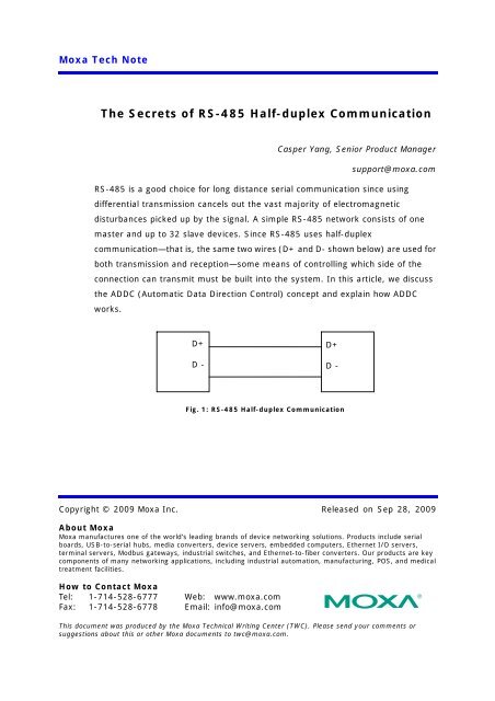
master and up to 32 slave devices. Since <strong>RS</strong>-<strong>485</strong> uses half-<strong>duplex</strong><br />
communication—that is, the same two wires (D+ and D- shown below) are used for<br />
both transmission and reception—some means <strong>of</strong> controlling which side <strong>of</strong> the<br />
connection can transmit must be built into the system. In this article, we discuss<br />
the ADDC (Automatic Data Direction Control) concept and explain how ADDC<br />
works.<br />
D+<br />
D -<br />
Fig. 1: <strong>RS</strong>-<strong>485</strong> <strong>Half</strong>-<strong>duplex</strong> <strong>Communication</strong><br />
This document was produced by the <strong>Moxa</strong> Technical Writing Center (TWC). Please send your comments or<br />
suggestions about this or other <strong>Moxa</strong> documents to twc@moxa.com.<br />
D+<br />
D -
<strong>Moxa</strong> Tech Note <strong>The</strong> <strong>Secrets</strong> <strong>of</strong> <strong>RS</strong>-<strong>485</strong> <strong>Half</strong>-<strong>duplex</strong><br />
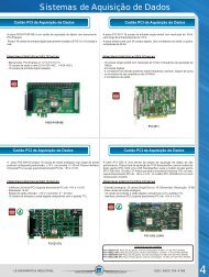
<strong>The</strong> most common way <strong>of</strong> controlling the transmit (Tx) and receive (Rx) direction is<br />
to use an RTS signal between the UART and the <strong>RS</strong>-<strong>485</strong> half-<strong>duplex</strong> wiring. By<br />
adding a simple logic circuit (see Fig. 2), you can turn RTS on or <strong>of</strong>f to switch the<br />
direction between Tx and Rx. That is, to transmit data you turn RTS on, and then<br />
you turn it <strong>of</strong>f when the transmission is finished. Although the overall concept is<br />
easy to describe and understand, devising a precise enough timing mechanism can<br />
be quite a challenge.<br />
UART<br />
RTS<br />
Tx<br />
Rx<br />
D +<br />
D -<br />
Fig. 2: Using RTS to Control Data Direction<br />
In most cases, the <strong>RS</strong>-<strong>485</strong> bus uses a master-slave architecture, which requires<br />
that each device on the <strong>RS</strong>-<strong>485</strong> bus have a unique id. <strong>The</strong> master will send a<br />
command with an id and ask each slave to respond one by one. <strong>The</strong> default RTS<br />
state is <strong>of</strong>f, which means that all devices are in the Rx state and are waiting to<br />
receive data (either a command or a response to a command) from one <strong>of</strong> the other<br />
devices. A typical scenario is as follows:<br />
(1) <strong>The</strong> master switches to the Tx state, transmits a command to query a device,<br />
and then switches back to the Rx state and waits for a response.<br />
(2) <strong>The</strong> slave whose id matches the id queried by the master switches to the Tx<br />
state, transmits its response, and then switches back to the Rx state.<br />
Copyright © 2009 <strong>Moxa</strong> Inc. Page 2 <strong>of</strong> 5
<strong>Moxa</strong> Tech Note <strong>The</strong> <strong>Secrets</strong> <strong>of</strong> <strong>RS</strong>-<strong>485</strong> <strong>Half</strong>-<strong>duplex</strong><br />
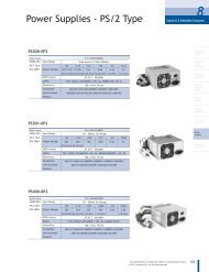
If the master switches back to the Rx state too slowly, it will not receive the entire<br />
response. If the master switches back too quickly, the command will not be sent<br />
correctly. To control the timing properly, you need to know when the data was sent<br />
out.<br />
Master<br />
Slave<br />
Master-RTS<br />
If too fast, the slave cannot receive<br />
all commands from the master.<br />
Tx: Command<br />
Rx State<br />
Good<br />
Timing<br />
Fig. 3: Using RTS to Control Direction<br />
Rx State<br />
Response<br />
If too slow, the master cannot receive<br />
all responses from the slave.<br />
UART Holding and Shift Registers—For Controlling the UART Directly<br />
With the UART’s Transmitter Empty Interrupt (TxINT) enabled, you may think it’s<br />
okay to turn the RTS to <strong>of</strong>f if no more data need to be sent. However, checking the<br />
TxINT value will only tell you that the holding register is empty, when in fact an<br />
additional byte could still be transmitting from the shift register. <strong>The</strong> UART’s<br />
transmit shift register is used to transmit data bit by bit. Every time you put data in<br />
the FIFO, the UART will move data into the shift register automatically. To confirm<br />
that the shift register is empty, you need to read the Line Status Register (LSR) and<br />
check if both the Transmitter Holding Register Empty (THRE) bit and Transmitter<br />
Empty (TEMT) bit are set or not. If both are set, it is safe to turn the RTS to <strong>of</strong>f.<br />
Copyright © 2009 <strong>Moxa</strong> Inc. Page 3 <strong>of</strong> 5
<strong>Moxa</strong> Tech Note <strong>The</strong> <strong>Secrets</strong> <strong>of</strong> <strong>RS</strong>-<strong>485</strong> <strong>Half</strong>-<strong>duplex</strong><br />
UART Enhanced Mode with TTL Setting—For Controlling the UART Directly<br />
To improve performance some advanced UARTs, such as the 16950 and <strong>Moxa</strong>’s<br />
MU150/MU860, support “Transmit Interrupt Trigger Level” (TTL). This level defines<br />
when the UART needs to issue a Transmitter Empty Interrupt (TxINT) and cause<br />
the Interrupt Service Routine (ISR) to put more data into the UART. With this level<br />
set to a nonzero value, the UART can issue an interrupt even though some data is<br />
still queued in the Tx FIFO. To work properly in an <strong>RS</strong>-<strong>485</strong> application, you need to<br />
set TTL to zero. This means that if you get a TxINT, the UART holding register and<br />
shift register are empty and you can turn RTS to <strong>of</strong>f immediately if no more data in<br />
the buffer needs to be sent.<br />
Applications in Win32 and UNIX/Linux—For Serial Application<br />
Programmers<br />
In most cases, you do not need to control the UART manually, and instead just use<br />
the API provided by the operating system. You can use WriteFile() for Win32<br />
systems, and write() for UNIX/Linux systems. Win32 provides the function<br />
RTS_CONTROL_TOGGLE to work with the RTS automatically. If fRtsControl is set to<br />
this value in the DCB structure by calling SetCommState(), the driver should turn<br />
RTS on automatically before sending the data and turn RTS <strong>of</strong>f automatically when<br />
it finishes. Before using this approach, you should first make sure that it is<br />
supported by the vendor if you are using a serial expansion solution (which means<br />
that you are not using serial.sys, Windows’ built-in serial port driver). If<br />
RTS_CONTROL_TOGGLE is not supported, controlling RTS manually will cause a lot<br />
<strong>of</strong> timing problems, and is not reliable.<br />
For UNIX/Linux, the POSIX tty API does not support the RTS toggle function, and<br />
you need to control RTS manually. In this case, you can call tcdrain() to wait until<br />
data is sent and turn RTS <strong>of</strong>f. <strong>The</strong> problem is that tty drivers only check the driver<br />
buffer and UART holding register. Unfortunately, there is no way to confirm that the<br />
shift register is empty. If you really want to use <strong>RS</strong>-<strong>485</strong> in UNIX/Linux with RTS<br />
control, you need to modify the driver or call your vendor for support.<br />
Copyright © 2009 <strong>Moxa</strong> Inc. Page 4 <strong>of</strong> 5
<strong>Moxa</strong> Tech Note <strong>The</strong> <strong>Secrets</strong> <strong>of</strong> <strong>RS</strong>-<strong>485</strong> <strong>Half</strong>-<strong>duplex</strong><br />
Working with Virtual Serial Ports—For Serial Application Programmers<br />
If the serial port is a “virtual” port, such as is created by a USB-to-serial or<br />
Ethernet-to-serial product, it’s not easy to know when all the data has been sent<br />
out because the driver needs to work with the firmware in the product and not a<br />
real UART. For virtual serial drivers, the write operation will be finished immediately<br />
when the data is moved to the local driver buffer. This is good for performance but<br />
is not good for <strong>RS</strong>-<strong>485</strong> RTS control. If you turn RTS <strong>of</strong>f immediately when the write<br />
operation is finished, the data will still be transmitting, which will cause problems.<br />
In this case, in Win32 you can use RTS_CONTROL_TOGGLE if it is supported by the<br />
driver. If not, you need to see if the driver supports an advanced option (such as<br />
<strong>Moxa</strong>’s “classical mode” in UPort and NPort) for confirming that all data will be sent<br />
out before the WriteFile() is returned. For virtual serial ports it is impossible to<br />
control RTS manually without RTS_CONTROL_TOGGLE or classical mode supported<br />
in Windows/UNIX/Linux.<br />
Controlling RTS Automatically—For Everyone<br />
Controlling RTS by s<strong>of</strong>tware (driver or application) can give rise to a number <strong>of</strong><br />
problems, and consequently many hardware vendors solve this problem by<br />
controlling the direction automatically. This means that the <strong>RS</strong>-<strong>485</strong> hardware can<br />
switch the Tx/Rx direction automatically, such as is done with <strong>Moxa</strong>’s ADDC<br />
(Automatic Data Direction Control) function. It is compatible with existing s<strong>of</strong>tware<br />
and if you want to transmit commands over the <strong>RS</strong>-<strong>485</strong> bus, you can just send,<br />
instead <strong>of</strong> worrying about controlling the RTS signal. <strong>The</strong> hardware will detect the<br />
action and switch to the Tx state automatically. Note that some converter products<br />
require users to configure the baudrate first. Please read the manual <strong>of</strong> your<br />
product for detailed information.<br />
Conclusion<br />
A good way to simplify <strong>RS</strong>-<strong>485</strong> implementation is to choose a product that supports<br />
ADDC. With ADDC you do not need to waste time modifying your programming to<br />
match the timing. You can keep your existing programming as is, and rest assured<br />
that it works with ADDC. Controlling the RTS on/<strong>of</strong>f process will be ignored by<br />
ADDC, and all you need to do is configure the hardware properly.<br />
Copyright © 2009 <strong>Moxa</strong> Inc. Page 5 <strong>of</strong> 5