User's Manual - from Measurement Computing
User's Manual - from Measurement Computing
User's Manual - from Measurement Computing

Create successful ePaper yourself
Turn your PDF publications into a flip-book with our unique Google optimized e-Paper software.
DaqBoard/1000 and /2000 Series User’s <strong>Manual</strong>For PCI-bus & Compact PCI-bus Data Acquisition BoardsIOtech, Inc.25971 Cannon RoadCleveland, OH 44146-1833Phone: (440) 439-4091Fax: (440) 439-4093E-mail (Product Information): sales@iotech.comE-mail (Technical Support): productsupport@iotech.comInternet: www.iotech.comDaqBoard/1000 & /2000 SeriesUser’s <strong>Manual</strong>For PCI-bus & Compact PCI-busData Acquisition Boardsp/n 1033-0901 Rev. 8.0© 1999 through 2005 by IOtech, Inc. 879194 Printed in the United States of America
Warranty InformationYour IOtech warranty is as stated on the product warranty card. You may contact IOtech by phone,fax machine, or e-mail in regard to warranty-related issues.Phone: (440) 439-4091, fax: (440) 439-4093, e-mail: sales@iotech.comLimitation of LiabilityIOtech, Inc. cannot be held liable for any damages resulting <strong>from</strong> the use or misuse of this product.Copyright, Trademark, and Licensing NoticeAll IOtech documentation, software, and hardware are copyright with all rights reserved. No part of this product may becopied, reproduced or transmitted by any mechanical, photographic, electronic, or other method without IOtech’s priorwritten consent. IOtech product names are trademarked; other product names, as applicable, are trademarks of theirrespective holders. All supplied IOtech software (including miscellaneous support files, drivers, and sample programs)may only be used on one installation. You may make archival backup copies.CE NoticeMany IOtech products carry the CE marker indicating they comply with the safety and emissions standards of theEuropean Community. As applicable, we ship these products with a Declaration of Conformity stating whichspecifications and operating conditions apply.Warnings, Cautions, Notes, and TipsRefer all service to qualified personnel. This caution symbol warns of possible personal injury or equipment damageunder noted conditions. Follow all safety standards of professional practice and the recommendations in this manual.Using this equipment in ways other than described in this manual can present serious safety hazards or cause equipmentdamage.This warning symbol is used in this manual or on the equipment to warn of possible injury or death <strong>from</strong> electricalshock under noted conditions.This ESD caution symbol urges proper handling of equipment or components sensitive to damage <strong>from</strong> electrostaticdischarge. Proper handling guidelines include the use of grounded anti-static mats and wrist straps, ESD-protectivebags and cartons, and related procedures.This symbol indicates the message is important, but is not of a Warning or Caution category. These notes can be ofgreat benefit to the user, and should be read.In this manual, the book symbol always precedes the words “Reference Note.” This type of note identifies the locationof additional information that may prove helpful. References may be made to other chapters or other documentation.Tips provide advice that may save time during a procedure, or help to clarify an issue. Tips may include additionalreference.Specifications and CalibrationQuality NoticeSpecifications are subject to change without notice. Significant changes will be addressed in an addendum or revision tothe manual. As applicable, IOtech calibrates its hardware to published specifications. Periodic hardware calibration isnot covered under the warranty and must be performed by qualified personnel as specified in this manual. Impropercalibration procedures may void the warranty.IOtech has been an ISO 9001 registered firm since 1996. Prior to shipment, we thoroughly test our products andreview our documentation to assure the highest quality in all aspects. In a spirit of continuous improvement,IOtech welcomes your suggestions.DaqBoard/1000 and /2000 Series User’s <strong>Manual</strong>iii
Your order was carefully inspected prior to shipment. When you receive your system, carefullyunpack all items <strong>from</strong> the shipping carton and check for physical signs of damage that may haveoccurred during shipment. Promptly report any damage to the shipping agent and your salesrepresentative. Retain all shipping materials in case the unit needs returned to the factory.CAUTIONUsing this equipment in ways other than described in this manual can causepersonal injury or equipment damage. Before setting up and using yourequipment, you should read all documentation that covers your system.Pay special attention to Warnings and Cautions.Note:PDF1033-0901During software installation, Adobe ® PDF versions of user manuals will automaticallyinstall onto your hard drive as a part of product support. The default location is in thePrograms group, which can be accessed <strong>from</strong> the Windows Desktop. Initialnavigation is as follows:Start [Desktop “Start” pull-down menu]⇒ Programs⇒ IOtech DaqX SoftwareYou can also access the PDF documents directly <strong>from</strong> the data acquisition CD by usingthe button located on the opening screen.Refer to the PDF documentation for details regarding both hardware and software.A copy of the Adobe Acrobat Reader ® is included on your CD. The Reader providesa means of reading and printing the PDF documents. Note that hardcopy versions ofthe manuals can be ordered <strong>from</strong> the factory.DaqBoard 1000 and 2000 Series.pdfContains the DaqBoard/1000 and /2000 Series hardware-related and software-relatedchapters, as well as links to the .pdf files listed below. This pdf file, plus thefollowing constitute a complete set of documentation for the DaqBoards discussed.Note that the Programmer’s <strong>Manual</strong> (1008-0901) and the DBK Option Cards &Modules(457-0905) are completely separate documents. The later does not apply toDaqBoard/1000 Series boards.DaqView.pdfPDF457-0909Discusses how to install and use this “out-of-the-box” data acquisition program.PDF1086-09261086-0922PostAcquisition Analysis.pdfThis pdf consists of two documents. The first discusses eZ-PostView, a post dataacquisition analysis program. The application is included free as a part of DaqTempproduct support. The second includes information regarding eZ-FrequencyView andeZ-TimeView. These two applications have more features than does eZ-PostView andare available for purchase. They can; however, be used freely during a 30-day trialperiod.ivDaqBoard/1000 and /2000 Series User’s <strong>Manual</strong>
PDF457-0905DBK Options.pdfThe DBK Option Cards and Modules <strong>Manual</strong> discusses each of the DBK productsavailable at the time of print. The DBK Options document does not apply toDaqBoard/1000 Series boards.PDF1008-0901Programmers <strong>Manual</strong>.pdfThe programmer’s manual pertains to developing custom programs usingApplications Program Interface (API) commands.Programmers should check the readme.file on the install CD-ROM for the location ofprogram examples included on the CD.DaqBoard/1000 and /2000 Series User’s <strong>Manual</strong>v
viDaqBoard/1000 and /2000 Series User’s <strong>Manual</strong>
<strong>Manual</strong> LayoutDaqBoard/1000 and /2000 Series, Installation Guide (p/n 1033-0940)DaqBoard/2000c Series, Installation Guide (p/n 1061-0940)Chapter 1 – Daq Systems and Device Overviews. This chapter begins with a discussion of the “modularconcept” that is associated with Daq data acquisition systems. The chapter then goes on to providean overview for each DaqBoard/1000 and /2000 Series board.Chapter 2 –Connections and Pinouts, DaqBoard/1000 Series - This chapter includes board pinouts forthe DaqBoard/1000 Series 68-pin connector. It includes screw terminal identification for TB-100,which is an optional terminal board connector.Chapter 3 - Connections and Pinouts, DaqBoard/2000 Series - This chapter includes board pinoutsfor the DaqBoard/2000 Series boards’ 100-pin connector (P4). The chapter includes an overview ofthe DBK200 Series P4 adapters that can be used to obtain DB37 type connectors (P1, P2, and P3).Chapter 4 - CE Compliance pertains to CE standards and conditions that are relevant to DaqBoard/1000and /2000 Series boards. A CE Kit, which can be used for DaqBoard/2000 Series boards, is alsodiscussed.Chapter 5 - Calibration lists the order in which to perform calibration-related adjustments and brieflydiscusses DaqCal.exe, a program that provides on-screen instruction, graphics, and prompts.GlossaryReference Notes:During software installation, Adobe ® PDF versions of user manuals are automaticallyinstalled onto your hard drive as a part of product support. The default location is in thePrograms directory, which can be accessed <strong>from</strong> the Windows Desktop.A copy of the Adobe Acrobat Reader ® is included on your CD. The Reader providesa means of reading and printing the PDF documents. Note that hardcopy versions of manualscan be ordered <strong>from</strong> the factory.‣ DaqView – explains the use and features of the included out-of-the-box dataacquisition software.‣ Post Acquisition Data Analysis User’s Guide – discusses three post-acquisition dataanalysis programs: eZ-PostView, eZ-TimeView, and eZ-FrequencyView.‣ For detailed information regarding specific DBKs, refer to the DBK Option Cardsand Modules User’s <strong>Manual</strong>, p/n 457-0905. Each DBK section includes devicespecifichardware and software information. The document includes a chapter onpower management. DaqBoard/1000 Series boards do not support DBK options.‣ For programming-related information refer to the separate Programmer’s <strong>Manual</strong>,p/n 1008-0901.DaqBoard/1000 and /2000 Series User’s <strong>Manual</strong> 959695 vii
This page is intentionally blank.viii 969594 DaqBoard/1000 and /2000 Series User’s <strong>Manual</strong>
Table of ContentsDaqBoard/1000 and /2000 Series, Installation Guide (p/n 1033-0940)DaqBoard/2000c Series, Installation Guide (p/n 1061-0940)1 – Daq Systems and Device OverviewsDaq Systems, the Modular Concept ……1-1Theory of Operation, DaqBoard/1000 and/2000 Series Boards…… 1-3DaqBoard/1000 ….. 1-7DaqBoard/1005 ….. 1-9DaqBoard/2000…… 1-11DaqBoard/2001 …… 1-13DaqBoard/2002 …… 1-15DaqBoard/2003 …… 1-17DaqBoard/2004 …… 1-19DaqBoard/2005 …… 1-21Using DBK Cards & Modules for Signal Conditioning ……1-23Note: DBK options do not apply to DaqBoard/1000 Series BoardsDaq Software …… 1-23Specifications – DaqBoard/1000 Series Boards …… 1-25Specifications – DaqBoard/2000 Series Boards …… 1-292 – Connections and Pinouts, DaqBoard/1000 SeriesOverview …… 2-1TB-100 Terminal Connector Option …… 2-2Pinouts for DaqBoard/1000 Series Boards …… 2-33 – Connections and Pinouts, DaqBoard/2000 SeriesOverview …… 3-1DBK200 Series, P4 Connector Options …… 3-2Pinouts for DaqBoard/2000 Series and /2000c Series Boards …… 3-84 – CE-ComplianceOverview …… 4-1CE Standards and Directives …… 4-1Safety Conditions …… 4-2Emissions/Immunity Conditions …… 4-2CE Enhancements for DBKs ...... 4-3CE Cable Kits for DaqBoard/2000 Series and /2000c Series Boards…… 4-35 – CalibrationGlossaryDaqBoard/1000 and /2000 Series User’s <strong>Manual</strong> 959695 ix
This page is intentionally blank.x 969594 DaqBoard/1000 and /2000 Series User’s <strong>Manual</strong>
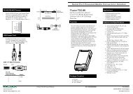
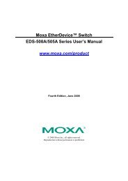
DaqBoard/1000 and /2000 SeriesInstallationThis guide tells how to complete the following steps for a successful installation.Step 1 – Install Software …… page 2Step 2 – Install Boards in Available PCI Bus-Slots …… page 3Step 3 – Configure Boards ….. page 5Step 4 – Test Hardware ….. page 6Reference Note:After you have completed the installation you should refer to the electronic documents thatwere automatically installed onto your hard drive as a part of product support. The defaultlocation is in the Programs group, which can be accessed <strong>from</strong> the Windows Desktop.You should keep your DaqBoard’s serial number and your DaqView/2000 authorization code (ifapplicable) with this document. Space is provided below for recording up to 4 board numbers and theirPCI bus-slot locations. The board serial number is located on the connector as indicated in the followingfigure.Serial Number Location on DaqBoard/2000 Series ConnectorThe location is similar for DaqBoard/1000 Series Board.Board Type (e.g.,1000, 1005, 2000,2001, etc.)*Serial NumberPCI Bus-Slot LocationBoard 1Board 2Board 3Board 4The host PC can support up to four Boards.*Note: DaqBoards have device labels which read, for example, “DaqBoard/1000,” “DaqBoard/2001,” “DaqBoard/2002,”etc. The name labels are convenient for users of more than one board type.DaqView/2000 Authorization Code ____________________________Customers who ordered DaqView/2000 can find their authorization code on the authorization code sheet located inside the sleeve of the install CD.Note that earlier documents may refer to this as a “registration code” or “registration ID.”Customers who did not order DaqView/2000 can run a 30-day free trial version, as discussed elsewhere in the User’s <strong>Manual</strong>.CAUTIONTake ESD precautions (packaging, proper handling, grounded wrist strap, etc.)Use care to avoid touching board surfaces and onboard components. Only handle boards by theiredges (or ORBs, if applicable). Ensure boards do not come into contact with foreign elements such asoils, water, and industrial particulate.© 1999 through 2004 by IOtech, Inc. 898195 1033-0940, rev. 8.0 IG-1
Reference Notes:(1) Each DaqBoard plugs into a PCI bus-slot. Consult your PC owner’s manual as needed.(2) DaqBoard/2000 Series users should read about the DBK cards and modules applicable to their acquisition system.Specific DBK information can be found in the world wide web at http://www.daqboard.com; and in the DBK Option Cardsand Modules User’s <strong>Manual</strong> (p/n 457-0905). After the install you can navigate to the DBK manual and other relevantelectronic documents <strong>from</strong> your desktop as follows: Start ⇒ Programs ⇒ IOtech DaqX Software ⇒ DaqBoard 2000Series UsersNote: DaqBoard/1000 Series boards do not support DBK options.Reference Note: Adobe PDF versions of user manuals willautomatically install onto your hard drive as a part of productsupport. The default location is in the Programs group, whichcan be accessed <strong>from</strong> the Windows Desktop. Refer to the PDFdocumentation for details regarding both hardware andsoftware. Note that hardcopy versions of the manuals can beordered <strong>from</strong> the factory.Minimum System RequirementsPC system with Pentium ® ProcessorWindows Operating SystemRAM, as follows:32 Mbytes of RAM for Windows 95/98/NT64 Mbytes of RAM for Windows Me64 Mbytes of RAM for Windows 200064 Mbytes of RAM for Windows XPInstallation, A Pictorial OverviewStep 1 – Install SoftwareIMPORTANT: Software must be installed before installing hardware.1. Remove previous version Daq drivers, if present. You can do this through Microsoft’s Add/RemovePrograms feature.2. Place the Data Acquisition CD into the CD-ROM drive. Wait for PC to auto-run the CD. This maytake a few moments, depending on your PC. If the CD does not auto-run, use the Desktop’sStart/Run/Browse feature and run the Setup.exe file.3. After the intro-screen appears, follow the screen prompts.Upon completing the software installation, continue with step 2, Install Boards in availablePCI Bus-slots.IG-2 DaqBoard/1000 and /2000 Series Installation Guide 898195 1033-0940, rev 8.0
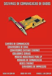
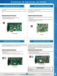
Step 2 – Install Boards in available PCI Bus-slotsIMPORTANT: Software must be installed before installing hardware.CAUTIONTurn off power to, and UNPLUG the host PC and externally connected equipment prior toremoving the PC’s cover and installing the DaqBoard. Electric shock or damage to equipmentcan result even under low-voltage conditions.Take ESD precautions (packaging, proper handling, grounded wrist strap, etc.)Use care to avoid touching board surfaces and onboard components. Only handle boards by theiredges (or ORBs, if applicable). Ensure boards do not come into contact with foreign elements suchas oils, water, and industrial particulate.IMPORTANT: Bus Mastering DMA must be Enabled.For a DaqBoard/1000 or /2000 Series board to operate properly, Bus Mastering DMA must beEnabled on the PCI slot [for which the board is to be installed]. Prior to installation, verify thatyour computer is capable of performing Bus Mastering DMA for the applicable PCI slot. Note thatsome computers have BIOS settings that enable [or disable] Bus Mastering DMA. If yourcomputer has this BIOS option, ensure that Bus Mastering DMA is Enabled on the appropriatePCI slot.Refer to your PC Owner's <strong>Manual</strong> for additional information regarding your PC and enablingBus Mastering DMA for PCI slots.1. Turn off power to, and UNPLUG the host PC and externally connected equipment.2. Remove the PC’s cover. Refer to your PC Owner’s <strong>Manual</strong> as needed.3. Choose an available PCI bus-slot.4. Carefully remove the DaqBoard <strong>from</strong> its anti-static protective bag. If you have not already done so,write down the serial number of your board at this time.5. Refer to the figure at the right. Remove the screw thatsecures the blank adapter plate, which is associated with thePCI slot you will be using. Refer to your PC Owner’s<strong>Manual</strong> if needed.6. Remove the blank adapter plate.Removing a Blank Adapter Plate1033-0940, rev 8.0 898195 DaqBoard/1000 and /2000 Series Installation Guide IG-3
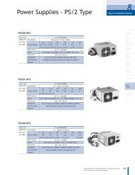
7. Refer to the figure at the right. Align the groove in theDaqBoard’s PCI edge-connector with the ridge of thedesired PCI slot, and with the PC’s corresponding rearpanelslot.8. Push the board firmly into the PCI slot. The board willsnap into position.9. Secure the board by inserting the rear-panel adapter-platescrew.10. Using the previous steps, install additional boards intoavailable PCI bus-slots, if applicable to your application.11. Replace the computer’s cover.12. Plug in all cords and cables that were removed in step 1.13. Apply power to, and start up the PC.Installing a DaqBoard/2000 Series BoardNote: At this point some PCs may prompt you to insert aninstallation disk. While this is rare, if you do receive such aprompt simply place the install CD-ROM into the disk driveand follow additional screen prompts.IG-4 DaqBoard/1000 and /2000 Series Installation Guide 898195 1033-0940, rev 8.0
Using “Add Device”This method is for users who have accessed the Daq Configurationcontrol panel applet, but have no DaqBoard1K icon or DaqBoard2K icon[as described on page IG-5, step 2].(A) After accessing the Daq Configuration control panel applet, click onthe button (see figure, right). The Select Device Typewindow will appear.(B) Using the Device Type’s pull-down list, select the applicable board.In the example at the right DaqBoard/2000 is selected.(C) Click the button. The board’s Properties tab will appear.Note that this tab will apply to all boards in the series.At this point, complete steps 3 through 5 <strong>from</strong> page IG-5.Step 4 – Test HardwareUsing “Add Device”Use the following steps to test the DaqBoard board. Note that these steps are continued <strong>from</strong> those listed under theprevious section, “Configure Board.”1. Select the “Test Hardware” tab.2. Click the “Resource Test” button.3. After the test is complete, click “OK.”System capability is now tested for the DaqBoard and a listof test results appears on screen.Note: If you experience difficulties, please consult your userdocumentation (included on your CD) before calling fortechnical support. Note that the user documentationincludes a troubleshooting chapter, as well as a greatdeal of information regarding specific DBK cards andmodules, which can be used with DaqBoard/2000systems.Test Hardware Tab(Condensed Screen Image)At this point we are ready to connect signals.• For DaqBoard/2000 Series boards, signal connection is typically accomplished with the use of aDBK200 Series option.• For DaqBoard/1000 Series boards, connection is typically made via a terminal board, such as theoptional TB-100.Reference Notes:‣ DaqBoard/2000 Series users: For detailed information regarding the DBK200 Series options, referto the DBK Option Cards and Modules User’s <strong>Manual</strong> (p/n 457-0905).‣ During software installation, Adobe ® PDF versions of user manuals are automatically installed ontoyour hard drive as a part of product support. The default location is in the Programs group, whichcan be accessed <strong>from</strong> the Windows Desktop. A copy of the Adobe Acrobat Reader ® is included onyour CD. The Reader provides a means of reading and printing the PDF documents. Note thathardcopy versions of manuals can be ordered <strong>from</strong> the factory.IG-6 DaqBoard/1000 and /2000 Series Installation Guide 898195 1033-0940, rev 8.0
DaqBoard/2000c SeriesInstallationThis guide tells you how to complete the following steps for a successful installation.Step 1 – Install Software …… page 2Step 2 – Install Boards into Available, 5 Volt, Compact-PCI Bus-Slots …… page 2Step 3 – Configure Boards ….. page 4Step 4 – Test Hardware ….. page 5Reference Note:After you have completed the installation you should refer to the electronic documents thatwere automatically installed onto your hard drive as a part of product support. The defaultlocation is in the Programs group, which can be accessed <strong>from</strong> the Windows Desktop.You should keep your DaqBoard/2000c Series board’s serial number and your DaqView/2000authorization code (if applicable) with this document. Space is provided below for recording up to 4 boardnumbers and their compact-PCI bus-slot location. Board serial numbers are located on the 100-pin P4connector.Board Typee.g., DaqBoard/2005cSerial NumberCompact-PCI Bus-Slot LocationBoard 1Board 2Board 3Board 4Compact PC support for DaqBoard/2000c Series boards varies. A system can support no more than four boards.*Note: The DaqBoard/2000c Series boards have their board identity indicated on the latch, as indicated inthe photo on the front page of this guide. This identification is provided since the boards look verymuch alike and are visually identical once installed.DaqView/2000 Authorization Code ____________________________Customers who ordered DaqView/2000 can find their authorization code on the authorization code sheet located inside thesleeve of the install CD. Customers who did not order DaqView/2000 can run a 30-day free trial version, as discussed in theuser’s manual.CAUTIONTake ESD precautions (packaging, proper handling, grounded wrist strap, etc.)Use care to avoid touching board surfaces and onboard components. Only handleboards by their edges (or ORBs, if applicable). Ensure boards do not come into contactwith foreign elements such as oils, water, and industrial particulate.Reference Note:During software installation, Adobe ® PDF versions of user manuals are automatically installedonto your hard drive as a part of product support. The default location is in the Programsgroup, which can be accessed <strong>from</strong> the Windows Desktop. A copy of the Adobe AcrobatReader ® is included on your CD. The Reader provides a means of reading and printing thePDF documents. Note that hardcopy versions of manuals can be ordered <strong>from</strong> the factory.Note:In regard to functionality, the DaqBoard/2000c Series boards are identical to theirDaqBoard/2000 Series counterparts.© 2001 through 2004 by IOtech, Inc. 979294 1061-0940, rev. 4.0 IG-1
Reference Notes:‣ Each DaqBoard/2000c Series Board plugs into a 5 volt, compact-PCI bus-slot located on the PC’s backplane. Notethat the 5 V compact-PCI bus-slot contains a blue key (see page 3). Consult your PC owner’s manual as needed.‣ Be sure to read about the DBK cards and modules applicable to your acquisition system. Specific DBK informationcan be found in on the world wide web at http://www.daqboard.com; and in your DBK Option Cards and ModulesUser’s <strong>Manual</strong> (p/n 457-0905). After the install you can navigate to the DBK manual and other relevant electronicdocuments <strong>from</strong> your desktop as follows:Start ⇒ Programs ⇒ IOtech DaqX Software ⇒ DaqBoard 2000 Series UsersReference Note: Adobe PDF versions of user manuals willautomatically install onto your hard drive as a part of productsupport. The default location is in the Programs group, whichcan be accessed <strong>from</strong> the Windows Desktop. Refer to the PDFdocumentation for details regarding both hardware andsoftware. Note that hardcopy versions of the manuals can beordered <strong>from</strong> the factory.Minimum System RequirementsPC system with Pentium ® ProcessorWindows Operating SystemRAM, as follows:32 Mbytes of RAM for Windows 95/98/NT64 Mbytes of RAM for Windows Me64 Mbytes of RAM for Windows 200064 Mbytes of RAM for Windows XPStep 1 – Install SoftwareIMPORTANT: Software must be installed before installing hardware.1. Remove previous version Daq drivers, if present. You can do this through Microsoft’s Add/RemovePrograms feature.2. Place the Data Acquisition CD into the CD-ROM drive. Wait for PC to auto-run the CD. This maytake a few moments, depending on your PC. If the CD does not auto-run, use the Desktop’sStart/Run/Browse feature.3. After the intro-screen appears, follow the screen prompts.Upon completing the software installation, continue with step 2, Install Boards in available 5 Volt,Compact-PCI Bus-slots.Step 2 – Install Boards in available 5 Volt, Compact-PCI Bus-slotsIMPORTANT: Software must be installed before installing hardware.IMPORTANT: Bus Mastering DMA must be Enabled.For a DaqBoard/2000c Series board to operate properly, Bus Mastering DMA must be enabled.Prior to installation, verify that your computer is capable of performing Bus Mastering DMA forthe applicable compact-PCI bus-slot. Note that some computers have BIOS settings that enable[or disable] Bus Mastering DMA. If your computer has this BIOS option, ensure that BusMastering DMA is Enabled on the appropriate compact-PCI bus-slot.Refer to your PC’s owner manual for additional information regarding Bus Mastering DMA.IMPORTANT: The Compact-PCI Bus-Slot must be keyed for 5 Volt use.Note: The 5 Volt Key location is indicated in the first photograph on page 3.IG-2 DaqBoard/2000c Series Installation Guide 979294 1061-0940, rev 4.0
CAUTIONTurn power OFF, and UNPLUG the host PC and externally connected equipment prior toremoving any cover plates or modules. Electric shock or damage to equipment can result evenunder low-voltage conditions.Take ESD precautions (packaging, proper handling, grounded wrist strap, etc.)Use care to avoid touching board surfaces and onboard components. Only handle boards by theiredges or ORBs. Ensure boards do not come into contact with foreign elements such as oils, water,and industrial particulate.1. Turn the PC’s power OFF.2. Turn power OFF to externally connected equipment.VoltageKey3. UNPLUG the host PC and all externally connectedequipment.4. Remove the computer’s compact-PCI bus-slot cover plate[or remove an unwanted module, if applicable].Refer to your PC Owner’s <strong>Manual</strong> as needed.5. Verify that the available compact-PCI bus slot is for5 volt applications.The computer’s 5 volt compact-PCI bus-slots can berecognized by a blue voltage key that is located in thecenter of the slot (see figure).6. Carefully remove the DaqBoard/2000c Series Board<strong>from</strong> its anti-static protective bag. If you have notalready done so, write down the serial number of yourboard at this time. The serial number is located on the100-pin P4 connector.7. With the board’s injector/ejector down, guide the boardinto the PC’s slot. Note that the top and bottom edges ofthe board locate in edge-guides, within the PC.8. Push the board back into the PC to engage the board’scompact-PCI connector with the computer’s compact-PCI bus-slot.9. Pull the board’s injector/ejector up. This will fullyengage the connectors.10. Secure the board by tightening the upper and lower lockscrews.11. Using the previous steps, install additional boards intoavailable compact-PCI bus-slots, if applicable to yourapplication.Note: The lower lock screw is accessed through an openingon the injector/ejector as indicated in the right-handfigure.Compact-PCI Bus-Slot with Blue 5 Volt Identifier KeyInjector/EjectorUpper Lock ScrewLower Lock Screw(see note)Installing a DaqBoard/2000c Series BoardLower LockScrewInjector/Ejector and Lower Lock Screw1061-0940, rev 4.0 979294 DaqBoard/2000c Series Installation Guide IG-3
12. Plug in all cords and cables that were removed in step 3.13. Apply power to, and start up the PC.Note: At this point some PCs may prompt you to insert aninstallation disk. While this is rare, if you do receivesuch a prompt simply place the install CD into the diskdrive and follow the screen prompts.Securing a DaqBoard/2000c Series BoardStep 3 – Configure BoardsDaqBoard/2000c Series boards have no jumpers or switches to set. Configuration is performed entirely through software.Refer to the following figure and steps to complete the configuration. The numbers in the figure correspond to the numberedsteps immediately following the figure.Accessing the DaqBoard/2000 Properties TabIG-4 DaqBoard/2000c Series Installation Guide 979294 1061-0940, rev 4.0
1. Run the Daq Configuration control panel applet. Navigation <strong>from</strong> the desktop to the applet is as follows:Start ⇒ Settings ⇒ Control Panel ⇒ Daq*Configuration (double-click)2. Double-click on the Device Inventory’s DaqBoard2K0 icon. The DaqBoard/2000 Properties tab (used for the entireDaqBoard/2000 Series) will appear. If the DaqBoard2K0 icon is not present, skip to the Using ‘Add Device’ sectionprovided below.3. Enter a “Device Name” in the text box, or use the default “DaqBoard2K0.” Device Name is for identifying the specificDaqBoard/2000 Series board. Note that Device Name actually refers to the PCI slot and not to the actual board.4. Verify that the “Device Type” shows the correct DaqBoard/2000 Series board, e.g., “DaqBoard/2000, DaqBoard/2001,etc.” Note that available device types can be viewed via the pull-down list ().5. Confirm that the DaqBoard/2000 Series text box shows a Bus #, Slot #, and Serial Number.If this text box is empty, use its pull-down list () and select the serial number that matches the one for your board.Refer to the inside front cover page for serial number information.Using “Add Device”This method is for users who have accessed the Daq Configuration control panelapplet, but have no DaqBoard2K icon (as described instep 2, above).(A) After accessing the Daq Configuration control panel applet, click on the AddDevice button (see figure, right). The Select Device Type window will appear.(B) Using the Device Type’s pull-down list, select the applicable board. In theexample at the right DaqBoard/2000 is selected.(C) Click the OK button. The DaqBoard/2000 Properties tab will appear. This tabapplies to all boards in the DaqBoard/2000 Series.At this point, complete steps 3 through 5 <strong>from</strong> above.Using “Add Device’Step 4 – Test HardwareUse the following steps to test the DaqBoard/2000 Series board. Note that these steps are continued <strong>from</strong> those listedunder the previous section, “Configure Board.”1. Select the “Test Hardware” tab.2. Click the “Resource Test” button.3. After the test is complete, click “OK.”System capability is now tested for the DaqBoard/2000Series board and a list of test results appears on screen.Note: If you experience difficulties, please consult your userdocumentation (included on your CD) before calling fortechnical support. Note that the user documentationincludes a troubleshooting chapter, as well as a greatdeal of information regarding specific DBK cards andmodules.Test Hardware Tab (Condensed Screen Image)At this point we are ready to connect signals. This is typically accomplished with the use of a DBK200 Series option.Reference Note:For detailed information regarding the DBK200 Series options, refer to the DBK Option Cards and ModulesUser’s <strong>Manual</strong> (p/n 457-0905).During software installation, Adobe ® PDF versions of user manuals are automatically installed onto yourhard drive as a part of product support. The default location is in the Programs group, which can beaccessed <strong>from</strong> the Windows Desktop. A copy of the Adobe Acrobat Reader ® is included on your CD. TheReader provides a means of reading and printing the PDF documents. Note that hardcopy versions ofmanuals can be ordered <strong>from</strong> the factory.1061-0940, rev 4.0 979294 DaqBoard/2000c Series Installation Guide IG-5
IG-6 DaqBoard/2000c Series Installation Guide 979294 1061-0940, rev 4.0
Daq Systems and Device Overviews 1Daq Systems, the Modular Concept …… 1-1Theory of Operation, DaqBoard/1000 and /2000 Series Boards …… 1-3DaqBoard/1000 …… 1-7DaqBoard/1005 …… 1-9DaqBoard/2000 ….… 1-11DaqBoard/2001……. 1-13DaqBoard/2002…… 1-15DaqBoard/2003…… 1-17DaqBoard/2004…… 1-19DaqBoard/2005…… 1-21Using DBK Cards and Modules for Signal Conditioning ….. 1-23Daq Software ……1-23Specifications - DaqBoard/1000 Series Board …… 1-25Specifications – DaqBoard/2000 Series Boards …… 1-29Daq Systems, the Modular ConceptDaq equipment and software form a modular, interrelated family of products that provide great flexibilityin data acquisition system design. This flexibility allows for the development of custom systems that areunique to the user, and which can be optimized for his or her specific application needs. With the Daqproduct line, system expansion or redesign can typically be accomplished with relative ease.• Primary Acquisition Device. This is the main data acquisition device, e.g., a DaqBook, DaqBoard,or Daq PC-Card. These devices provide a vital data conversion and communications link betweenthe data source of transducers and signal conditioners and the data processor of the host computer.Note that a DaqBoard can be one of three types: (1) ISA, (2) PCI, or (3) compact-PCI.• DBK Option Cards and Modules. Over 35 DBK cards and modules (the number is constantlygrowing) provide various types of signal conditioning and system expansion. Note that certain DBKmodules exist for the purpose of supplying power to other members of the acquisition system. TheDBK options are discussed in a DBK Basics document module and in the detailed DBK OptionCards and User’s <strong>Manual</strong> (p/n 457-0905). DaqBoard/1000 Series boards do not support DBKoptions.Note: Only passive DBKs, such as the DBK1 BNC module, the DBK11A screw terminal card, andthe DBK40 BNC analog interface, can be used with a Daq PC-Cards.Reference Note:DBK options are discussed in the DBK Option Cards and Modules User’s <strong>Manual</strong>(p/n 457-0905). As a part of product support, this manual is automatically loaded ontoyour hard drive during software installation. The default location is the Programsdirectory, which can be accessed through the Windows Desktop.• Software. DaqView out-of-the-box software provides a graphical user interface with easy to readspreadsheet formats for viewing channel data, as well as a choice of analog, digital, and bar-graphmeters. Waveform analysis can be performed, when applicable. A product support option, includedon the data acquisition CD, provides a means of performing post data analysis. More information isincluded in the software-specific PDF documents that are installed on your hard-drive as a part ofproduct support.DaqBoard/1000 and /2000 Series User’s <strong>Manual</strong> 957995 Daq Systems and Device Overviews 1-1
In addition to the included out-of-the-box software, Daq products can be controlled via user-writtencustom programs through Applications Program Interface (API). Several languages are supported,including C/C++ and VisualBASIC.DaqView and DASYLab can only be used with one DaqBoard at a time.LabView can be used with multiple boards. For multiple board use (via customprogramming) refer to the Using Multiple Devices section of the Programmer’s <strong>Manual</strong>.Reference Note:Programming topics are covered in the Programmer’s User <strong>Manual</strong> (p/n 1008-0901). As a partof product support, this manual is automatically loaded onto your hard drive during softwareinstallation. The default location is the Programs group, which can be accessed through theWindows Desktop.Daq Data Acquisition DevicesCategory Device DescriptionPrimaryAcquisitionDeviceDBK OptionCards andModules*SoftwareDaqBookDaqBoard/1000Series*DaqBoard/2000SeriesDaqBoard/2000cSeriesDaqBoard (ISA types)Daq PC-CardAnalog SignalConditioningAnalog OutputDigital I/O and ControlExpansionConnectionsPower Supply DBKs: 30A, 32A, 33, 34Included SoftwareOptional SoftwarePortable Data Acquisition Modules12-bit: DaqBook/100, /112, /12016-bit: DaqBook/200, /216, /260, /2001, /2005, /2020Plug-In Boards for PCI Bus-Slots16-bit , 200 kHz. 2 boards identified as /1000 and /1005Make use of a 68-pin SCSI III connector.The DaqBoard/1000 Series boards do not support DBK options.Plug-In Boards for PCI Bus-Slots16-bit , 200 kHz. Six boards identified as /2000 through /2005.Make use of a 100-pin connector (P4).Plug-In Boards for Compact-PCI Bus-Slots16-bit , 200 kHz. Six boards identified as /2000c through /2005c.Make use of a 100-pin connector (P4).Unless otherwise specified, documentation discussing a DaqBoard/2000series board also applies to a DaqBoard/2000c Series board.Plug-In Boards for ISA Bus-Slots12-bit: DaqBoard/100A, /112A16-bit: DaqBoard/200A, /216A, /2000Plug-In PCMCI Card12-bit: Daq/112B16-bit: Daq/216BCards and modules used to condition Analog SignalsDBK/ 4, 7, 8, 9, 12, 13, 15, 17, 18, 19, 42, 43A, 44, 45, 50, 51, 52, 53, 54,55, 65, 80, 81, 82, 83, 84, 85, 90, 100, 207, 207/CJCCards used to modify Analog Output SignalsDBK/ 2, 5Cards and modules used to condition Digital I/ODBK/ 20, 21, 23, 24, 25, 208, 210Cards and modules used to expand the acquisition system.DBK/ 1, 10, 11A, 35, 40, 41, 60, 200, 201, 202, 203, 204, 205, 206, 209DaqView, Post Data Acquisition Analysis Program (actual application notspecified), Visual Basic extensions, Application Programming Interface(API)DaqView/2000, DaqViewXL, DASYLab* DBK Option cards and modules are not supported by DaqBoard/1000 Series boards.1-2 Daq Systems and Device Overviews 929095 DaqBoard/1000 and /2000 Series User’s <strong>Manual</strong>
Theory of OperationI/O Comparison Matrixfor DaqBoard/1000 and /2000 Series BoardsAs implied by the following matrix, the operational material does not apply globally to every board. Forexample, DaqBoard/1005, /2002, and /2005 have no analog output channels.For ease of understanding, each board is discussed independently, following the matrix. Note that pinoutsare provided in chapter 2 for the DaqBoard/1000 Series and in chapter 3 for the DaqBoard/2000 Series.I/O Comparison Matrixfor DaqBoard/1000 and /2000 Series BoardsDaqBoardIdentityAnalog InputChannelsAnalog OutputChannelsDigital I/OChannelsCounterInputsTimerOutputs1000 16 2 24 4 21005 16 -- 24 4 22000 16 2 40 4 22001 16 4 40 4 22002 -- -- 40 4 22003 -- 4 -- -- --2004 -- 4 40 4 22005 16 -- 40 4 2Note: DaqBoard/1000 Series boards do not support DBK options.DaqBoard/1000 and /2000 Series User’s <strong>Manual</strong> 929095 Daq Systems and Device Overviews 1-3
Synchronous Input Operations for DaqBoard/1000 and DaqBoard/2000 Series BoardsAs indicated in the I/O matrix, applicable DaqBoards allow for synchronous scanning and acquisition ofAnalog Input, Digital Input and Counter Input Data at up to 200kHz aggregate scanning rates.For applicable DaqBoard/2000 Series devices, the Analog Input data can be either directly to the board or<strong>from</strong> expansion analog input modules connected to P1. The Digital Input data can be to the board’s 8-bitP2 (8255) digital inputs, 16-bit P3 digital inputs or P2 compatible DBK digital input expansion modules.Refer to the applicable pinouts to see how P1, P2, and P3 relate to the 100-pin P4 connector.DaqBoard/1000 Series boards do not support DBK options.Analog Input ChannelsThe boards that offer analog input (see previous matrix) allow analog input configuration for the board.For applicable DaqBook/2000 Series boards, analog input can be received <strong>from</strong> P1 compatible DBKanalog input expansion modules.Channel Selection and Mode SettingsThe main unit accepts up to 16 single ended or up to 8 differential-ended inputs and can be programmedfor single-ended or differential-ended on a per channel basis. In regard to DaqBoard/2000 Series boards,just one analog channel is sacrificed when a DBK expansion module is enabled. See DBK documentationin the DBK Option Cards & Modules User’s <strong>Manual</strong> (p/n 457-0905) for further information.Channel Range and PolarityDaqBoard/2000 Series board channels can be programmed for either unipolar or bipolar mode with gainsettings of 1,2,4,8,16,32 and 64. DaqBoard/1000 Series boards have the same gains but are only bipolar.Channel Sampling IntervalThe boards allow programmable sampling intervals of 5us or 10us on a per channel basis. This modeallows some channels which change slowly but a higher degree of accuracy is desirable to be sampled at alonger interval while channels that change more rapidly to be sampled using a shorter interval. Each 5us or10us interval reduces the maximum aggregate acquisition rate for the entire scan by that amount.Digital Input ChannelsAssociated boards allow either synchronous scanning of digital input channels or asynchronous I/Ooperations for all configured digital channels.Counter Input ChannelsAssociated boards allow synchronous scanning of the 4 16-bit counter input channels. The four 16-bitcounter channels can also be cascaded into two 32-bit counter channels. For either cascaded ornon-cascaded counter channels each channel can be configured for:• Pulse Counting Mode – specifies that each counter should be cleared upon being read and placed intothe input scan.• Totalize Counting Mode – specifies that each counter is to free-run and not be cleared during the inputacquisition.Synchronous Input Acquisition ClockingAssociated boards allow clocking of the synchronized inputs either by an internal, programmable pacerclock or by external clocking. These products use a sequencer to implement a multiplexing approach togathering the input data. This means that with either internal or external clocking the entire channel scan(including the sampling time for each channel) may not exceed the maximum aggregate rate of 200kHz.1-4 Daq Systems and Device Overviews 929095 DaqBoard/1000 and /2000 Series User’s <strong>Manual</strong>
Synchronous Output OperationsThe DaqBoard/1000 allows synchronous output of any D/A channels available at up to 100kHz for eachchannel. All D/A channels available may have output streamed to them and clocked out synchronously.The D/A channels may be configured for waveform output.The DaqBoard/2000 Series boards allow synchronous output of any D/A or P3 16-bit Digital channelsavailable at up to 100kHz for each channel. All D/A channels available and the 16-bit P3 Digital channelmay have output streamed to them and clocked out synchronously. The D/A channels may be configuredfor waveform output and the P3 digital channel may be configured for streamed digital pattern output usingthe same clock sources.Output Channel ConfigurationAnalog Output ChannelsEach D/A channel can be configured for waveform output individually. If the D/A channel is notconfigured for waveform output it then is available for asynchronous output operations.Digital Pattern Output Channel (DaqBoard/2000 Series Only)In regard to DaqBook/2000 Series boards, the 16-bit P3 Digital Port can be configured for streamed digitalpattern output. If not configured for streamed digital pattern output operations it then may be used forasynchronous digital I/O operations.Synchronous Output ClockingAssociated boards allow clocking of the synchronized output by the acquisition clock source, an internal,programmable pacer clock or by an external clock source. When the clock source generates a new clocksignal all outputs are updated concurrently. Regardless of the clock source, the clock may not exceed themaximum update rate of 100kHz.Synchronous Output Data SourceAssociated boards allow the data source for synchronized output operations to be that of a memory basedbuffer or a file located on a mass storage medium. With either type of output data source, the output datafor all the channels are contained in the buffer and/or file. The file path may be any file located on themachine or network accessible file.Asynchronous I/O OperationsAssociated boards allow asynchronous input of any counter or digital channel that is not currentlyconfigured for synchronous acquisition. The boards also allow for asynchronous output to any D/Achannels not currently configured for waveform output.In addition, for DaqBoard/2000 Series boards, the 16-bit P3 digital port can be used for both asynchronousinput and output operations if it is not currently configured for streamed pattern output operations. Also,the timer outputs can be programmed at any time regardless of the current state of synchronous orasynchronous operations on other channels.Digital I/O ChannelsLocal 8255 ChannelsThe boards [which have digital I/O capabilities] have an implemented Intel 8255 core in the digital I/Ologic. For DaqBoard/2000 Series boards, this is applicable to the P2 port [see pinouts for P2 to P4relationship]. With the Intel 8255 there are three 8-bit wide ports available for I/O and one 8-bit wide portfor configuration purposes. The configuration port is used to configure the other three 8-bit ports for eitherinput or output operations.Local 16-bit P3 Port (DaqBoard/2000 Series only)For DaqBoard/2000 series devices, the 16-bit P3 Digital Port can be used as either an input, or an outputport. With this port, no configuration is required as the port simply outputs when written to and inputswhen read.DaqBoard/1000 and /2000 Series User’s <strong>Manual</strong> 929095 Daq Systems and Device Overviews 1-5
Operation Matrix*Expansion Digital I/O (DaqBoard/2000 Series only)The DaqBoard/2000 Series boards that have digital I/O capabilities have the ability to expand thesethrough the P2 port and the connection of applicable digital I/O expansion modules. These modules arediscussed in the DBK Option Cards & Modules User’s <strong>Manual</strong>. When using the digital I/O expansionmodules the local P2 Intel 8255 digital I/O becomes inaccessible in lieu of the expansion modules. Theseexpansion modules provide additionally Intel 8255 ports as well as input isolation for applications thatrequire the expanded capabilities.Pulse Stream Output Using TimersThe boards allow the generation of output pulses based upon a programmable setting. These output timerscan be set at any time regardless of the state of any synchronous or asynchronous operations which arecurrently taking place on other channels.Analog Output ChannelsThe boards that have analog output capabilities have the ability to output analog data to any of theavailable (up to four) D/A channels. Each D/A channel may be asynchronously updated by an applicationif the D/A channel is not currently being used for waveform output operations.Counter Input ChannelsWith exception of DaqBoard/2003, the boards have counter input capabilities and have the ability to readcounter input [if the counter channel is not configured for synchronous acquisition]. As in the case ofsynchronous operations the 4 16-bit counter input channels can be used individually or cascaded into two32-bit counter channels. For either cascaded or non-cascaded counter channels each channel can beconfigured for:• Clear on Read Mode - specifies that each counter should be cleared (reset to 0) upon being read.• Continuous Totalize Mode – specifies that each counter is to free-run and not be cleared duringthe read operation.Operation 1000 1005 2000 2001 2002 2003 2004 2005Synchronous InputAnalog Main Unit Inputs Yes Yes Yes Yes No No No YesAnalog Expansion Input No No Yes Yes No No No YesCounter Inputs Yes Yes Yes Yes Yes No Yes YesDigital Main Unit Inputs Yes Yes Yes Yes Yes No Yes YesDigital Expansion Inputs No No Yes Yes Yes No Yes YesSynchronous OutputAnalog D/A Waveform Output Yes No Yes Yes No Yes Yes NoStreamed Digital Output (16-bit) No No Yes Yes Yes No Yes YesAsynchronous IOMain Unit Digital I/O Yes Yes Yes Yes Yes No Yes YesExpansion Digital I/O No No Yes Yes Yes No Yes YesTimer Output (Pulse Generation) Yes Yes Yes Yes Yes No Yes YesAnalog Output Yes No Yes Yes No Yes Yes No* A similar matrix, intended to highlight board differences at a glance, is presented on page 1-3.1-6 Daq Systems and Device Overviews 929095 DaqBoard/1000 and /2000 Series User’s <strong>Manual</strong>
DaqBoard/100016 AnalogInput2 AnalogOutput24 DigitalI/O4 CounterInputs2 TimerOutputsDaqBoard/1000 is a high-speed, multi-function, plug-and-play data acquisition board for PCI buscomputers. It features a 16-bit, 200-kHz A/D converter, digital calibration, bus mastering DMA, two16-bit, 100-kHz D/A converters, 24 digital I/O lines, four counters, and two timers.Up to four boards can be installed into a PC.One 68-pin SCSI III connector on the board provides access to all of the input and output signals. TheDaqBoard/1000 accommodates all I/O with one cable and one PCI slot.The 68-pin I/O connector is logically divided into three functions:• Analog input for16 single-ended or 8 differential analog inputs with 7 software programmable bipolarranges (±10 V to ±156 mV full scale).• 24 lines of general purpose digital I/O.• 4 counter inputs, 2 timer outputs, and 2 analog outputs.The on-board scan sequencer lets you select up to 512 channel/range combinations. The sequencer scansall channels of the scan at 5µs or 10 µs/channel.Bus mastering allows analog and digital/counter input data, as well as analog and digital output data, toflow between the PC and the DaqBoard without consuming CPU time.DaqBoard/1000 supports trigger modes that include:• Digital and pattern triggering – The boards have separate digital trigger input line, allowing TTLleveltriggering and latencies less than 5 µs. The trigger can be programmed for logic level or edgetriggering. In pattern triggering, any of the digital input ports acts as the trigger port. You can programthe digital pattern.• Software-based triggering – The PC detects the trigger event <strong>from</strong> analog, digital, or counterreadings. Six pre- and post-triggering modes are supported.The two 16-bit, 100-kHz analog output channels have an output <strong>from</strong> –10 V to +10 V. Using BusMastering DMA, each D/A can output a waveform.Other features of the DaqBoard/1000 include:• 24 TTL-level digital I/O lines. They are divided into three 8-bit ports.• Four 16-bit counters. Each can accept frequency inputs up to 10 MHz. The counters can be cascadedinto two 32-bit counters.• Two 16-bit timer outputs. Each can generate square waves <strong>from</strong> 16 Hz to 1 MHz.• Configuration through software. There are no switches or jumpers on the DaqBoard/1000.DaqBoard/1000 and /2000 Series User’s <strong>Manual</strong> 929095 Daq Systems and Device Overviews 1-7
DaqBoard/1000 Block DiagramConnectionsInstallationReference Note:For the DaqBoard/1000 installation procedure, refer to the DaqBoard/1000 and /2000 SeriesInstallation Guide. A copy of the guide is included at the beginning of this manual.I/O ConnectorsAll input and output signals are available at the board’s 68-pin SCSI III connector. Chapter 2 includes apinout. The following cable and terminal board options can be used to provide convenient screw terminalconnections for all signal I/O lines.Mating Cable: The CA-G56 is a 68-conductor shielded cable. It is used to connect a DaqBoard/1000Series board to a TB-100 termination board. The cable length is 3 feet.TB-100:TB-100 is an optional termination board. It provides convenient screw terminalconnections for all signal I/O lines of a DaqBoard/1000 Series board.Reference Note:The TB-100 terminal board connection option is discussed in chapter 2.1-8 Daq Systems and Device Overviews 929095 DaqBoard/1000 and /2000 Series User’s <strong>Manual</strong>
DaqBoard/100516 AnalogInputs24 DigitalI/O4 CounterInputs2 TimerOutputsDaqBoard/1005 is a high-speed, multi-function, plug-and-play data acquisition board for PCI buscomputers. It features a 16-bit, 200-kHz A/D converter, digital calibration, bus mastering DMA, 24 digitalI/O lines, four counters, and two timers.Up to four boards can be installed into a PC.One 68-pin SCSI III connector on the board provides access to all of the input and output signals. TheDaqBoard/1000 accommodates all I/O with one cable and one PCI slot. The 68-pin I/O connector islogically divided into three functions:• Analog input for16 single-ended or 8 differential analog inputs with 7 software programmable bipolarranges (±10 V to ±156 mV full scale).• 24 lines of general purpose digital I/O.• 4 counter inputs and 2 timer outputsThe on-board scan sequencer lets you select up to 512 channel/range combinations. The sequencer scansall channels of the scan at 5µs/channel or 10 µs/channel.Bus mastering allows analog and digital/counter input data, as well as digital output data, to flow betweenthe PC and the DaqBoard without consuming CPU time.DaqBoard/1005 supports trigger modes that include:• Digital and pattern triggering – The boards have separate digital trigger input line, allowing TTLleveltriggering and latencies less than 5 µs. The trigger can be programmed for logic level or edgetriggering. In pattern triggering, any of the digital input ports acts as the trigger port. You can programthe digital pattern.• Software-based triggering – The PC detects the trigger event <strong>from</strong> analog, digital, or counterreadings. Six pre- and post-triggering modes are supported.Other features of the DaqBoard/1000 include:• 24 TTL-level digital I/O lines. They are divided into three 8-bit ports.• Four 16-bit counters. Each can accept frequency inputs up to 10 MHz. The counters can be cascadedinto two 32-bit counters.• Two 16-bit timer outputs. Each can generate square waves <strong>from</strong> 16 Hz to 1 MHz.• Configuration through software. There are no switches or jumpers on the DaqBoard/1005.DaqBoard/1000 and /2000 Series User’s <strong>Manual</strong> 929095 Daq Systems and Device Overviews 1-9
DaqBoard/1005 Block DiagramConnectionsInstallationReference Note:For the DaqBoard/1005 installation procedure, refer to the DaqBoard/1000 and /2000 SeriesInstallation Guide. A copy of the guide is included at the beginning of this manual.I/O ConnectorsAll input and output signals are available at the board’s 68-pin SCSI III connector. Chapter 2 includes apinout. The following cable and terminal board options can be used to provide convenient screw terminalconnections for all signal I/O lines.Mating Cable: The CA-G56 is a 68-conductor shielded cable. It is used to connect a DaqBoard/1000Series board to a TB-100 termination board. The cable length is 3 feet.TB-100:TB-100 is an optional termination board. It provides convenient screw terminalconnections for all signal I/O lines of a DaqBoard/1000 Series board.Reference Note:The TB-100 terminal board connection option is discussed in chapter 2.1-10 Daq Systems and Device Overviews 929095 DaqBoard/1000 and /2000 Series User’s <strong>Manual</strong>
DaqBoard/200016 AnalogInput2 AnalogOutput40 DigitalI/O4 CounterInputs2 TimerOutputsDaqBoard/2000 and DaqBoard/2000c are high-speed, multi-function, plug-and-play data acquisitionboards for PCI and compact-PCI bus computers, respectively. They feature a 16-bit, 200-kHz A/Dconverter, digital calibration, bus mastering DMA, two 16-bit, 100-kHz D/A converters, 40 digital I/Olines, four counters, and two timers.Up to 470 channels of analog and digital I/O can be accessed with one DaqBoard/2000. Up to four boardscan be installed into a PC.A 100-pin connector on the boards provides access to all of the input and output signals. TheDaqBoard/2000 and /2000c accommodate all I/O with one cable and one PCI [or compact-PCI] slot.The 100-pin I/O connector, P4, is logically divided into three ports:• P1 – Analog input port for16 single-ended or 8 differential analog inputs with 13 softwareprogrammable ranges (±10 V to ±156 mV full scale).• P2 – General purpose digital I/O port with 24 lines, or digital I/O expansion port controlling up to 192external lines.• P3 – 16-bit digital I/O port, counter inputs, timer outputs, and analog outputs.The on-board scan sequencer lets you select up to 512 channel/range combinations. The sequencer scansall channels of the scan at 5µs or 10 µs/channel.Bus mastering allows analog and digital/counter input data, as well as analog and digital output data, toflow between the PC and the DaqBoard/2000 without consuming CPU time.DaqBoard/2000 supports a full complement of trigger modes including:• Hardware analog triggering – A user-programmed trigger level sets an analog DAC, which iscompared in hardware to the analog input level on the selected channel. Trigger latency is < 5 µs.• Digital and pattern triggering – The boards have separate digital trigger input line, allowing TTLleveltriggering and latencies less than 5 µs. The trigger can be programmed for logic level or edgetriggering. In pattern triggering, any of the digital input ports acts as the trigger port. You can programthe digital pattern.• Software-based triggering – The PC detects the trigger event <strong>from</strong> readings, either analog, digital, orcounter. Six pre- and post-triggering modes are supported.The two 16-bit, 100-kHz analog output channels have an output <strong>from</strong> –10 V to +10 V. (These channels areseparate <strong>from</strong> the D/As used to determine analog trigger levels.) Using Bus Mastering DMA, each D/A canoutput a waveform. Bus Mastering DMA also allows for digital pattern generation on the 16-bit high-speeddigital I/O port.Other features of the DaqBoard/2000 include:• 40 TTL-level digital I/O lines. They are divided into three 8-bit ports and one 16-bit port.• Four 16-bit counters. Each can accept frequency inputs up to 10 MHz. The counters can be cascadedinto two 32-bit counters.• Two 16-bit timer outputs. Each can generate square waves <strong>from</strong> 16 Hz to 1 MHz.• Configuration through software. There are no switches or jumpers on the DaqBoard/2000.DaqBoard/1000 and /2000 Series User’s <strong>Manual</strong> 929095 Daq Systems and Device Overviews 1-11
DaqBoard/2000 Block Diagram** The DaqBoard/2000c Block Diagram is the same, with exception that the /2000c board uses acompact-PCI Bus instead of a standard PCI bus.ConnectionsInstallationReference Note: For the DaqBoard/2000 and DaqBoard/2000c installation procedure, refer toeither the DaqBoard/1000 and /2000 Series Installation Guide or to the DaqBoard/2000cSeries Installation Guide, as applicable. The guides are included at the beginning of thismanual.I/O ConnectorsAll input and output signals are available at the board’s 100-pin P4 connector. A 3-foot, 100-conductorribbon cable, part number CA-195, mates with connector P4.Reference Note: There are several P4-connector board options available for connecting the100 pins of P4 to typical DB37 connectors (P1, P2, and P3). In addition to being brieflydiscussed in chapter 3 of this manual, these options, referred to as DBK200 Series, aredetailed in the DBK Cards and Modules User’s <strong>Manual</strong> (p/n 457-0905).1-12 Daq Systems and Device Overviews 929095 DaqBoard/1000 and /2000 Series User’s <strong>Manual</strong>
DaqBoard/200116 AnalogInput4 AnalogOutput40 DigitalI/O4 CounterInputs2 TimerOutputsDaqBoard/2001 and DaqBoard/2001c are high-speed, multi-function, plug-and-play data acquisitionboards for PCI or compact-PCI bus computers, respectively. They feature a 16-bit, 200-kHz A/Dconverter, digital calibration, bus mastering DMA, four 16-bit, 100-kHz D/A converters, 40 digital I/Olines, four counters, and two timers.Up to 470 channels of analog and digital I/O can be accessed with one DaqBoard/2001 board. Up to fourboards can be installed into a PC.A 100-pin connector on the DaqBoard/2001 provides access to all of the input and output signals. Theboards accommodate all I/O with one cable and one PCI [or compact-PCI] slot. The 100-pin I/O connector,P4, is logically divided into three ports:• P1 – Analog input port for16 single-ended or 8 differential analog inputs with 13 softwareprogrammable ranges (±10 V to ±156 mV full scale).• P2 – General purpose digital I/O port with 24 lines, or digital I/O expansion port controlling up to 192external lines.• P3 – 16-bit digital I/O port, counter inputs, timer outputs, and analog outputs.The on-board scan sequencer lets you select up to 512 channel/range combinations. The sequencer scansall channels of the scan at 5µs/channel or 10µs/channel.Bus mastering allows analog and digital/counter input data, as well as analog and digital output data, toflow between the PC and the DaqBoard/2001 without consuming CPU time.DaqBoard/2001 supports a full complement of trigger modes including:• Hardware analog triggering – A user-programmed trigger level sets an analog DAC, which iscompared in hardware to the analog input level on the selected channel. Trigger latency is < 5 µs.• Digital and pattern triggering – The DaqBoard/2001 has a separate digital trigger input line,allowing TTL-level triggering and latencies less than 5 µs. The trigger can be programmed for logiclevel or edge triggering. In pattern triggering, any of the digital input ports acts as the trigger port.You can program the digital pattern.• Software-based triggering – The PC detects the trigger event <strong>from</strong> readings, either analog, digital, orcounter. Six pre- and post-triggering modes are supported.The four 16-bit, 100-kHz analog output channels have an output <strong>from</strong> –10 V to +10 V. (These channelsare separate <strong>from</strong> the D/As used to determine analog trigger levels.) Using Bus Mastering DMA, each D/Acan output a waveform. Bus Mastering DMA also allows for digital pattern generation on the 16-bit highspeeddigital I/O port.Other features of the DaqBoard/2001 include:• 40 TTL-level digital I/O lines. They are divided into three 8-bit ports and one 16-bit port.• Four 16-bit counters. Each can accept frequency inputs up to 10 MHz. The counters can be cascadedinto two 32-bit counters.• Two 16-bit timer outputs. Each can generate square waves <strong>from</strong> 16 Hz to 1 MHz.• Configuration through software. There are no switches or jumpers on a DaqBoard/2001.DaqBoard/1000 and /2000 Series User’s <strong>Manual</strong> 929095 Daq Systems and Device Overviews 1-13
ConnectionsDaqBoard/2001 Block Diagram** The DaqBoard/2001c Block Diagram is the same, with exception that the /2001c board uses acompact-PCI Bus instead of a standard PCI bus.InstallationReference Note: For the DaqBoard/2001 and /2001c installation procedure, refer to either theDaqBoard/1000 and /2000 Series Installation Guide or to the DaqBoard/2000c SeriesInstallation Guide, as applicable. The guides are included at the beginning of this manual.I/O ConnectorAll input and output signals are available at the board’s 100-pin P4 connector. A 3-foot, 100-conductorribbon cable, part number CA-195, mates with connector P4.Reference Note: There are several P4-connector board options available for connecting the100 pins of P4 to typical DB37 connectors (P1, P2, and P3). In addition to being brieflydiscussed in chapter 3 of this manual, these options, referred to as DBK200 Series, aredetailed in the DBK Cards and Modules User’s <strong>Manual</strong> (p/n 457-0905).1-14 Daq Systems and Device Overviews 929095 DaqBoard/1000 and /2000 Series User’s <strong>Manual</strong>
DaqBoard/200240 DigitalI/O4 CounterInputs2 TimerOutputsDaqBoard/2002 and /2002c are high-speed, multi-function, plug-and-play data acquisition boards for PCIand compact-PCI bus computers, respectively. They feature digital calibration, bus mastering DMA,40 digital I/O lines, four counters, and two timers.Up to 470 channels of analog and digital I/O can be accessed with one board. Up to four boards can beinstalled into a PC.A 100-pin connector on the boards provides access to all of the input and output signals. The boardsaccommodate all I/O with one cable and one PCI [or compact-PCI] slot. The 100-pin I/O connector, P4, islogically divided into three ports:• P1 – Not used by DaqBoard/2002• P2 – General purpose digital I/O port with 24 lines, or digital I/O expansion port controlling up to192 external lines.• P3 – 16-bit digital I/O port, counter inputs, timer outputs, and analog outputs.The on-board scan sequencer lets you select up to 512 channel/range combinations. The sequencer scansall channels of the scan at 5 µs/channel or 10 µs/channel.Bus mastering allows digital/counter input data and digital output data to flow between the PC and theDaqBoard/2002 board without consuming CPU time.DaqBoard/2002 supports a complement of trigger modes including:• Digital and pattern triggering – The boards have separate digital trigger input line, allowing TTLleveltriggering and latencies less than 5 µs. The trigger can be programmed for logic level or edgetriggering. In pattern triggering, any of the digital input ports acts as the trigger port. You can programthe digital pattern.• Software-based triggering – The PC detects the trigger event <strong>from</strong> readings [digital, or counter].Six pre- and post-triggering modes are supported.Other features of the DaqBoard/2002 include:• 40 TTL-level digital I/O lines. They are divided into three 8-bit ports and one 16-bit port.• Four 16-bit counters. Each can accept frequency inputs up to 10 MHz. The counters can be cascadedinto two 32-bit counters.• Two 16-bit timer outputs. Each can generate square waves <strong>from</strong> 16 Hz to 1 MHz.• Configuration through software. There are no switches or jumpers on a DaqBoard/2002.DaqBoard/1000 and /2000 Series User’s <strong>Manual</strong> 929095 Daq Systems and Device Overviews 1-15
ConnectionsDaqBoard/2002 Block Diagram**The DaqBoard/2002c Block Diagram is the same, with exception that the /2002c board uses acompact-PCI Bus instead of a standard PCI bus.InstallationReference Note: For the DaqBoard/2002 and compact-PCI DaqBoard/2002c installationprocedure, refer to either the DaqBoard/1000 and /2000 Series Installation Guide or to theDaqBoard/2000c Series Installation Guide, as applicable. The guides are included at thebeginning of this manual.I/O ConnectorAll input and output signals are available at the board’s 100-pin P4 connector. A 3-foot, 100-conductorribbon cable, part number CA-195, mates with connector P4.Reference Note: There are several P4-connector board options available for connecting the100 pins of P4 to typical DB37 connectors (P1, P2, and P3). In addition to being brieflydiscussed in chapter 3 of this manual, these options, referred to as DBK200 Series, aredetailed in the DBK Cards and Modules User’s <strong>Manual</strong> (p/n 457-0905).1-16 Daq Systems and Device Overviews 929095 DaqBoard/1000 and /2000 Series User’s <strong>Manual</strong>
DaqBoard/20034 Analog OutputsDBK205TerminationsDaqBoard/2003 and /2003c are high-speed plug-and-play data acquisition boards for PCI and compact-PCIbus computers, respectively. The boards are used for analog output and include four 16-bit, 100-kHz D/Aconverters. Up to four boards can be installed into a PC.A 100-pin connector on the boards provides access to the DAC analog output signals. The boards plugdirectly into a PCI or compact-PCI bus slot, as applicable. The DAC analog output leaves the boardthrough “P3-designated” pins located on the board’s 100-pin P4 connector.Both boards support Software-based triggering. In “Software-based” triggering the PC detects thetrigger event <strong>from</strong> the readings. Six pre- and post-triggering modes are supported.TB1-1 AGNDTB1-2 DAC0TB1-3 AGNDTB1-4 DAC1TB1-5 AGNDTB1-6 DAC2TB1-7 AGNDTB1-8 DAC3TB1-9 AGNDTB1-10 XTTLTB1-11 CLKTB1-12 DGNDDBK205 AdapterDaqBoard/2003 Block DiagramNote: DaqBoard/2003 and DaqBoard/2003c are shipped with one DBK205 adapter. The adapter has twelve screwterminals as follows: DAC0, DAC1, DAC2, DAC3, 1 digital ground, 5 analog grounds, 1 external clock (CLK), and1 external trigger (XTTL). DBK205 connects directly to DaqBoard/2003’s P4 connector.ConnectionsInstallationI/O ConnectorReference Note: For the DaqBoard/2003 and DaqBoard/2003c installation procedure, refer toeither the DaqBoard/1000 and /2000 Series Installation Guide or to the DaqBoard/2000cSeries Installation Guide, as applicable. The guides are included at the beginning of thismanual.Analog output signals are available at the board’s 100-pin P4 connector. A 3-foot, 100-conductor ribboncable, part number CA-195, mates with connector P4; however, a DBK205 adapter board is included forconnecting the 100 pins of P4 to a terminal block (TB1).DBK205’s TB1 includes screw terminals for: DAC0, DAC1, DAC2, and DAC3, 1 digital ground,5 analog grounds, 1 external clock (CLK), and 1 external trigger (XTTL). DBK205 connects directly toDaqBoard/2003’s P4 connector or to a compact-PCI DaqBoard/2003c’s P4 connector.DBK205 is depicted as part of the block diagram above and is discussed briefly in chapter 3 of this manual.DBK205 is also discussed in the DBK Cards and Modules User’s <strong>Manual</strong> (p/n 457-0905).DaqBoard/1000 and /2000 Series User’s <strong>Manual</strong> 929095 Daq Systems and Device Overviews 1-17
1-18 Daq Systems and Device Overviews 929095 DaqBoard/1000 and /2000 Series User’s <strong>Manual</strong>
DaqBoard/20044 AnalogOutput40 DigitalI/O4 CounterInputs2 TimerOutputsDaqBoard/2004 and /2004c are high-speed, multi-function, plug-and-play data acquisition boards for PCIand compact-PCI bus computers, respectively. They feature bus mastering DMA, four 16-bit, 100-kHzD/A converters, 40 digital I/O lines, four counters, and two timers.Up to four boards can be installed in one PC.A 100-pin connector on the boards provides access to all of the input and output signals. Each boardaccommodates all I/O with one cable and one PCI [or compact-PCI] slot, as applicable. The 100-pin I/Oconnector, P4, is logically divided into three ports: P1, P2, and P3; however, DaqBoard/2004 only makesuse of the P2 and P3 pin designations.• P1 – Not used by DaqBoard/2004• P2 – General purpose digital I/O port with 24 lines, or digital I/O expansion port controlling up to 192external lines.• P3 – 16-bit digital I/O port, counter inputs, timer outputs, and analog outputs.The on-board scan sequencer lets you select up to 512 channel/range combinations. The sequencer scansall channels of the scan at 5 µs or 10 µs per channel.Bus mastering allows the digital/counter input data and analog and digital output data to flow between thePC and the DaqBoard/2004 without consuming CPU time.DaqBoard/2004 supports several trigger modes, including:• Digital and pattern triggering – Each board has a separate digital trigger input line, allowing TTLleveltriggering and latencies less than 5 µs. The trigger can be programmed for logic level or edgetriggering. In pattern triggering, any of the digital input ports acts as the trigger port. You canprogram the digital pattern.• Software-based triggering – The PC detects the trigger event <strong>from</strong> readings, either analog, digital, orcounter. Six pre- and post-triggering modes are supported.The four 16-bit, 100-kHz analog output channels have an output <strong>from</strong> -10 V to +10 V. Using BusMastering DMA, each D/A can output a waveform. Bus Mastering DMA also allows for digital patterngeneration on the 16-bit high-speed digital I/O port.Other features of the DaqBoard/2004 include:• 40 TTL-level digital I/O lines. They are divided into three 8-bit ports and one 16-bit port.• Four 16-bit counters. Each can accept frequency inputs up to 10 MHz. The counters can be cascadedinto two 32-bit counters.• Two 16-bit timer outputs. Each can generate square waves <strong>from</strong> 16 Hz to 1 MHz.• Configuration through software. There are no switches or jumpers on a DaqBoard/2004.DaqBoard/1000 and /2000 Series User’s <strong>Manual</strong> 929095 Daq Systems and Device Overviews 1-19
ConnectionsDaqBoard/2004 Block Diagram** The DaqBoard/2004c Block Diagram is the same, with exception that the /2004c board uses acompact-PCI Bus instead of a standard PCI bus.InstallationReference Note: For the DaqBoard/2004 and DaqBoard/2004c installation procedure, refer toeither the DaqBoard/1000 and /2000 Series Installation Guide or to the DaqBoard/2000cSeries Installation Guide, as applicable. The guides are included at the beginning of thismanual.I/O ConnectorAll input and output signals are available at the board’s 100-pin P4 connector. A 3-foot, 100-conductorribbon cable, part number CA-195, mates with connector P4.Reference Note: There are several P4-connector board options available for connecting the100 pins of P4 to typical DB37 connectors (P1, P2, and P3). In addition to being brieflydiscussed in chapter 3 of this manual, these options, referred to as DBK200 Series, aredetailed in the DBK Cards and Modules User’s <strong>Manual</strong> (p/n 457-0905).1-20 Daq Systems and Device Overviews 929095 DaqBoard/1000 and /2000 Series User’s <strong>Manual</strong>
DaqBoard/200516 AnalogInput40 DigitalI/O4 CounterInputs2 Timer OutputsDaqBoard/2005 and DaqBoard/2005c are high-speed, multi-function, plug-and-play data acquisitionboards for PCI and compact-PCI bus computers, respectively. They feature a 16-bit, 200-kHz A/Dconverter, digital calibration, bus mastering DMA, 40 digital I/O lines, four counters, and two timers.Up to 470 channels of analog and digital I/O can be accessed with one board. Up to four boards can beinstalled in one PC.A 100-pin connector on the board provides access to all of the input and output signals. The Each boardaccommodates all I/O with one cable and one PCI [or compact-PCI] bus-slot, as applicable. The 100-pinI/O connector, P4, is logically divided into three ports:• P1 – Analog input port for 16 single-ended or 8 differential analog inputs with 13 softwareprogrammable ranges (±10 V to ±156 mV full scale).• P2 – General purpose digital I/O port with 24 lines, or digital I/O expansion port controlling up to 192external lines.• P3 – 16-bit digital I/O port, counter inputs, and timer outputs.The on-board scan sequencer lets you select up to 512 channel/range combinations. The sequencer scansall channels of the scan at 5 µs/channel or 10 µs/channel.Bus mastering allows analog and digital/counter input data, as well as analog and digital output data, toflow between the PC and the board without consuming CPU time.DaqBoard/2005 supports a full complement of trigger modes, including:• Hardware analog triggering – A user-programmed trigger level sets an analog DAC, which iscompared in hardware to the analog input level on the selected channel. Trigger latency is < 5 µs.• Digital and pattern triggering – Both boards have a separate digital trigger input line, allowing TTLleveltriggering and latencies less than 5 µs. The trigger can be programmed for logic level or edgetriggering. In pattern triggering, any of the digital input ports acts as the trigger port. You can programthe digital pattern.• Software-based triggering – The PC detects the trigger event <strong>from</strong> readings, either analog, digital, orcounter. Six pre- and post-triggering modes are supported.Bus Mastering DMA also allows for digital pattern generation on the 16-bit high-speed digital I/O port.Other features of the DaqBoard/2005 include:• 40 TTL-level digital I/O lines. They are divided into three 8-bit ports and one 16-bit port.• Four 16-bit counters. Each can accept frequency inputs up to 10 MHz. The counters can be cascadedinto two 32-bit counters.• Two 16-bit timer outputs. Each can generate square waves <strong>from</strong> 16 Hz to 1 MHz.• Configuration through software. There are no switches or jumpers on a DaqBoard/2005.DaqBoard/1000 and /2000 Series User’s <strong>Manual</strong> 929095 Daq Systems and Device Overviews 1-21
ConnectionsDaqBoard/2005 Block Diagram**The DaqBoard/2005c Block Diagram is the same, with exception that the /2005c board uses acompact-PCI Bus instead of a standard PCI bus.InstallationReference Note:For the DaqBoard/2005 and compact-PCI DaqBoard/2005c installation procedure, refer toeither the DaqBoard/1000 and /2000 Series Installation Guide or to the DaqBoard/2000cSeries Installation Guide, as applicable. The guides are included at the beginning of thismanual.I/O ConnectorAll input and output signals are available at the board’s 100-pin P4 connector. A 3-foot, 100-conductorribbon cable, part number CA-195, mates with connector P4.Reference Note:There are several P4-connector board options available for connecting the 100 pins of P4 totypical DB37 connectors (P1, P2, and P3). In addition to being briefly discussed in chapter 3of this manual, these options, referred to as DBK200 Series, are detailed in the DBK Cardsand Modules User’s <strong>Manual</strong> (p/n 457-0905).1-22 Daq Systems and Device Overviews 929095 DaqBoard/1000 and /2000 Series User’s <strong>Manual</strong>
Using DBK Cards and Modules for Signal ConditioningThe DBK signal-conditioning cards and module are designed for use with DaqBooks, LogBooks, andvarious types of data acquisition boards, i.e., ISA, PCI, and compact-PCI types. The DBKs perform bestwhen used with an acquisition device that can dynamically select channel, gain, and range. DBK cards andmodules with dynamic channel and gain/range selection allow for high channel-to-channel scan rates witha variety of transducers.Note: Only passive DBKs, such as the DBK1 BNC module, the DBK11A screw terminal card, and theDBK40 BNC analog interface, can be used with Daq PC-Cards.DBK output signals can be bipolar, e.g., -5 to +5 V, or unipolar, e.g., 0 to 10 V. The user can select arange of relevant values to correspond to the lowest signal (e.g., -5 or 0 V) and the highest signal (e.g., 5 or10 V) signal. This type of range selection guarantees the highest resolution in 12-bit or 16-bit conversion.DBK modules share the same footprint as the DaqBook and a typical notebook PCs; allowing forconvenient stacking. The majority of these modules have their own power supply; however, severaloptions exist for packaging and powering the DBKs.Reference Note:DBK options are detailed in the DBK Option Cards and Modules User’s <strong>Manual</strong>(p/n 457-0905). As a part of product support, this manual is automatically loaded onto yourhard drive during software installation. The default location is the Programs directory, whichcan be accessed through the Windows Desktop.Daq SoftwareThe Daq devices have software options capable of handling most applications. Three types of software areavailable:• ready-to-use graphical programs, e.g., DaqView, DaqViewXL, and post acquisition data analysisprograms such as PostView, DIAdem, and eZ-PostView• drivers for third-party, icon-driven software such as DASYLab and LabView• various language drivers to aid custom programming using APIReady-to-use programs are convenient for fill-in-the-blank applications that do not require programmingfor basic data acquisition and display:• DaqView is a Windows-based program for basic set-up and data acquisition. DaqView lets youselect desired channels, gains, transducer types (including thermocouples), and a host of otherparameters with a click of a PC’s mouse. DaqView lets you stream data to disk and display datain numerical or graphical formats. PostView is a post-acquisition waveform-display programwithin DaqView.• DaqViewXL allows you to interface directly with Microsoft Excel to enhance data handling anddisplay. Within Excel you have a full-featured Daq control panel and all the data displaycapabilities of Excel.• Post acquisition data analysis programs, e.g., PostView, DIAdem, and eZ-PostView, typicallyallow you to view and edit post-acquisition data.• The Daq Configuration control panel allows for interface configuration, testing, andtroubleshooting.Each Daq system comes with an Application Programming Interface (API). API-language drivers includeC/C++ and Visual Basic. The latest software is a 32-bit version API.DaqBoard/1000 and /2000 Series User’s <strong>Manual</strong> 929095 Daq Systems and Device Overviews 1-23
Reference Notes:‣ The software document modules, DaqView, DaqViewXL, and Post AcquisitionData Analysis User’s Guide, are not included as part of the hardcopy manual, butare available in PDF version. See the PDF Note, below.‣ Programming topics are covered in the Programmer’s User <strong>Manual</strong> (1008-0901).As a part of product support, this manual is automatically loaded onto your harddrive during software installation. The default location is the Programs directory,which can be accessed through the Windows Desktop.PDFNote:During software installation, Adobe ® PDF versions of user manuals will automaticallyinstall onto your hard drive as a part of product support. The default location is in thePrograms directory, which can be accessed <strong>from</strong> the Windows Desktop. Refer to the PDFdocumentation for details regarding both hardware and software.A copy of the Adobe Acrobat Reader ® is included on your CD. The Reader providesa means of reading and printing the PDF documents. Note that hardcopy versions of themanuals can be ordered <strong>from</strong> the factory.1-24 Daq Systems and Device Overviews 929095 DaqBoard/1000 and /2000 Series User’s <strong>Manual</strong>
Specifications – DaqBoard/1000 SeriesNote: Specifications are subject to change without notice.I/O Comparison Matrixfor DaqBoard/1000 Series BoardsDaqBoardIdentityAnalog InputChannelsAnalog OutputChannelsDigital I/OChannelsCounterInputsTimerOutputs1000 16 2 24 4 21005 16 -- 24 4 2General Specifications Applicable to DaqBoard/1000, /1005Warm-up: 1 hour to rated specificationsSupply voltage range: 4.75 VDC to 5.25 VDC (PCI bus)Power consumption (per board): 3.5 WOperating temperature: 0 to +60°CStorage temperature: -40 to +80°CRelative Humidity: 0 to 95% non-condensingVibration: MIL STD 810ESignal I/O Connector: 68-pin SCSI type III, carries all analog I/O and digital I/ODimensions: 165 mm W x 15 mm D x 108 mm H (6.5” x 0.6” x 4.2”)Weight: 160 g (0.35 lbs)Analog Inputs Applicable to DaqBoard/1000, /1005Channels: 16 single-ended or 8 differential, programmable on a per-channel basis as singleendedor differential bipolar.Bandwidth: 500 kHzSettling Time: 5 µs maximum to 1 LSB for full-scale stepMaximum Input Voltage: +11V relative to analog commonOver-Voltage Protection: ±35VRanges: Software programmable via sequencer on a per-channel basis.Voltage Range(Note 1)Accuracy (Note 2)One Year, 0 to 35°C±(% reading + % range)AbsoluteInput Noise (Note 3)(LSB rms)10 Hz to 200 kHzTypical-10 to +10 V 0.015+.005 1-5 to +5 V 0.015+.005 1-2.5 to +2.5 V 0.015+.005 1-1.25 to +1.25 V 0.015+.005 2-0.625 to +0.625 V 0.015+.008 2-0.3125 to +0.3125 V 0.015+.008 3-0.156 to +0.156 V 0.02+.008 3Notes:1) Specifications assume differential input single channel scan, 200 kHz scan rate, unfiltered.2) Accuracy specification is exclusive of noise. <strong>Measurement</strong>s were taken at P1.3) Inputs shorted to signal ground (SGND). 8192 samples.DaqBoard/1000 and /2000 Series User’s <strong>Manual</strong> 929095 Daq Systems and Device Overviews 1-25
A/D Specifications Applicable to DaqBoard/1000, /1005Type: Successive approximation, 200 kHz maximum conversion rateResolution: 16 bitsConversion Time: 5 µsMaximum Sample Rate: 200 kHzDifferential Nonlinearity: ±2 LSB maximumIntegral Nonlinearity: ±1 LSB maximumMissing Codes: None, over full operating temperature rangeInput Sequencer Applicable to DaqBoard/1000, /1005Analog, digital and counter inputs can be scanned synchronously based either on an internalprogrammable timer, or an external clock source. Analog and digital outputs can be synchronized toeither of these clocks.Scan Clock Sources: 21. Internal, programmable <strong>from</strong> 5 µs to 5.96 hours maximum in 1 µs steps2. External, TTL level input up to 200 kHz maximumProgrammable parameters per scan: channel (random order), gainDepth: 512 locationOn-board Channel to channel scan rate: 5 or 10 µs per channel, programmableExternal Acquisition Scan Clock Input Applicable to DaqBoard/1000, /1005Maximum rate: 200 kHzClock Signal Range: 0V to +5VMinimum pulse width: 50 ns high, 50 ns lowTriggering Applicable to DaqBoard/1000, /1005Trigger Sources:4, individually selectable for starting and stopping an acquisition. Stop acquisitioncan occur on a different channel than start acquisition; stop acquisition can be triggered via modes 2,3, or 4 described below. Pre-trigger is supported with fixed or variable pre-trigger periods.1. Single-Channel Digital Trigger: A separate digital input is provided for digital triggering.Latency: 5 µs max.2. Digital Pattern Triggering: 8 or 16-bit pattern triggering on any digital input. Programmable fortrigger on equal, above, below, or within or outside of a window. Individual bits can be masked for“don’t care” condition. Latency: One scan period maximum.3. Counter/Totalizer Triggering: Counter/totalizer inputs can trigger an acquisition. User can selectto trigger on a frequency or on total counts that are equal, above, below, or within/outside of awindow. Latency: One scan period maximum.4. Software Triggering: Trigger can be initiated under program control.1-26 Daq Systems and Device Overviews 929095 DaqBoard/1000 and /2000 Series User’s <strong>Manual</strong>
Analog OutputsApplicable to DaqBoard/1000; does not apply to DaqBoard/1005Two analog output channels are updated synchronously relative to scanned inputs, and clocked <strong>from</strong>either an internal onboard clock, or an external clock source. Analog outputs can also be updatedasynchronously, independent of any other scanning in the system. Bus mastering DMA providesCPU and system-independent data transfers, ensuring accurate outputs that are irrespective of othersystem activities. Streaming <strong>from</strong> disk or memory is supported, allowing continuous, nearly-infinitelength, waveform outputs (limited only by available PC system resources).Channels: 2 DAC channels (DAC0, DAC1)Resolution: 16 bitsOutput voltage range: ±10 VDigital Feedthru: 50 mV when updatedOutput current: ±10 mAOffset error: ±0.0045 V maximumGain error: ±0.01%Update rate: 100 kHz maximum, 1.5 Hz minimum (no minimum with external clock)Settling Time: 10 µs maximum to 1 LSB for full-scale stepClock Sources: 4 programmable1. Onboard D/A clock, independent of scanning input clock2. Onboard scanning input clock3. External D/A input clock, independent of external scanning input clock4. External scanning input clockDigital I/O Applicable to DaqBoard/1000, /1005Channels: 24, expandable to 208 with external DBK optionsInput Scanning Modes: 2 programmable1. Asynchronous, under program control at any time relative to input scanning2. Synchronous with input scanningPorts: 3 x 8-bit (82C55 emulation). Each port is programmable as input or output.Input Characteristics: 100 Ω series, 20 pF to commonInput protection: ±8 kV ESD clamp diodes parallelI/O levels: TTLSampling/Update rate: 200 kHz maximumOutput Characteristics: Output 12 mA per pin, 200 mA total continuous (per bank of 24 outputs)Counters Applicable to DaqBoard/1000, /1005Counter inputs can be scanned synchronously along with analog and digital scanned inputs, basedeither on internal programmable timer, or an external clock source. Bus mastering DMA providesCPU and system-independent data transfers, insuring data acquisition performance irrespective ofother system activities. Counters can be configured to clear when read, or to totalize and clear underprogram control.Channels: 4 x 16-bit, cascadable as 2 x 32-bitFrequency <strong>Measurement</strong> Rate: 10 MHz maximumInput Signal Range: -15 V to +15 VInput Characteristics: 2.7 kΩ series in parallel with 20 pF to common and 10 kΩ to +5 VInput protection: ±8 kV ESD clamp diodes parallelTrigger Level: TTLMinimum pulse width: 50 ns high, 50 ns lowDaqBoard/1000 and /2000 Series User’s <strong>Manual</strong> 929095 Daq Systems and Device Overviews 1-27
Frequency/Pulse Generators Applicable to DaqBoard/1000, /1005Channels: 2 x 16-bitOutput Waveform: Square waveOutput rate: 1 MHz base rate divided by 1 to 65535 (programmable)High level output voltage: 2.0 V minimum @ -3.75 mA, 3.0 V minimum @ -2.5 mALow level output voltage: 0.4 V maximum @ 2.5 mAAccessories and Cables Applicable to DaqBoard/1000, /1005Termination Board (TB-100)Termination board with screw terminals for accessing all I/O for one DaqBoard/1000 orDaqBoard/1005. The terminal board connects to the DaqBoard/1000 Series board’s 68-pinconnector via a CA-G56 cable.Rack Mount Kit (Rack3)This is a kit for mounting the TB-100 termination board to a rack.68-Conductor Cable (CA-G56)68-conductor, 3 ft. shielded cable. Used to connect a TB-100 terminal board to a DaqBoard/1000 ora DaqBoard/1005.Software Applicable to DaqBoard/1000, /1005DaqView for setup, data acquisition display and analysis.DaqViewXL for seamless execution within Microsoft Excel’s tool palette.eZ-PostView for post acquisition viewing and analysis.1-28 Daq Systems and Device Overviews 929095 DaqBoard/1000 and /2000 Series User’s <strong>Manual</strong>
Specifications – DaqBoard/2000 Series BoardsNote: Specifications are subject to change without notice.I/O Comparison Matrixfor DaqBoard/2000 Series BoardsDaqBoardIdentityAnalog InputChannelsAnalog OutputChannelsDigital I/OChannelsCounterInputsTimerOutputs2000 16 2 40 4 22001 16 4 40 4 22002 -- -- 40 4 22003 -- 4 -- -- --2004 -- 4 40 4 22005 16 -- 40 4 2General Specifications Applicable to all DaqBoard/2000 Series BoardsWarm-up: 1 hour to rated specificationsSupply voltage range: 4.75 VDC to 5.25 VDC (PCI bus)Power consumption (per board): 3.5 W (up to 10 W with external accessories)Power Available for External Signal Conditioning and Expansion Options:5 V at 1 A (all boards); ±15 V at 75 mA each (with exception of DaqBoard/2002)Operating temperature: 0 to +60°CStorage temperature: -40 to +80°CRelative Humidity: 0 to 95% non-condensingVibration: MIL Std 810EDimensions:DaqBoard/2000 Series: 165 mm W x 15 mm D x 108 mm H (6.5” x 0.6” x 4.2”)DaqBoard/2000c Series: 160mm W x 19 mm D x 100 mm H (6.3” x 0.7” x 3.9”)Weight:DaqBoard/2000 Series: 160 g (0.35 lbs)DaqBoard/2000c Series: 178.95 g (0.39 lbs)DaqBoard/1000 and /2000 Series User’s <strong>Manual</strong> 929095 Daq Systems and Device Overviews 1-29
Analog Specifications Applicable to DaqBoard/2000, /2001, /2005A/D: Successive approximation, 200 kHz maximum conversion rateResolution: 16 bitsChannels: 16 single-ended or 8 differential, expandable up to 256 differentialConversion Time: 5 µsConnector: 100-pin high-density edge-typeMissing Codes: None, over full operating temperature rangeInput Voltage Ranges (software programmable via sequencer):Voltage RangeAccuracy (Note 2)One Year,0 to 35°C±(% reading+% range)Absolute Transfer (Note 3)Input Noise(LSB rms)10 Hz-200 kHz(Note 4)0 to +10 V 0.015+.005 0.004+.002 10 to +5 V 0.015+.005 0.004+.002 10 to +2.5 V 0.015+.005 0.004+.002 10 to +1.25 V 0.015+.008 0.004+.002 20 to +0.625 V 0.015+.008 0.004+.002 20 to +0.3125 V 0.015+.008 0.004+.003 2-10 to +10 V 0.015+.005 0.004+.001 1-5 to +5 V 0.015+.005 0.004+.001 1-2.5 to +2.5 V 0.015+.005 0.004+.001 1-1.25 to +1.25 V 0.015+.005 0.004+.001 2-0.625 to +0.625 V 0.015+.008 0.004+.001 2-0.3125 to +0.3125 V 0.015+.008 0.004+.0015 3-0.156 to +0.156 V 0.02+.008 0.004+.0015 3Notes(1) Specifications assumedifferential input single channelscan, 200 kHz scan rate,unfiltered.(2) Accuracy specification isexclusive of noise.(3) Transfer accuracy assumescalibration inside computer;applicable for measurementsmade ±5°C <strong>from</strong> ambienttemperature at calibration(4) Inputs shorted to P4-45A,differential input, 8192samples.Voltage Specifications (one year, 0-35°C) Applicable to DaqBoard/2000, /2001, /2005Differential Nonlinearity: ±2 LSB maximumIntegral Nonlinearity: ±1 LSB maximumTemperature Coefficient: ±(10 ppm + 0.3 LSB)/°C typicalInput Impedance: 10 MΩ (single ended); 20 MΩ (differential), in parallel with 50 pFBias Current:
Input Sequencer Applicable to DaqBoard/2000, /2001, /2002, /2004, /2005Analog, digital and counter inputs can be scanned synchronously based either on an internalprogrammable timer, or an external clock source. Analog and digital outputs can also besynchronized to either of these clocks. Bus Mastering DMA is utilized to provide CPU and systemindependentdata transfers, insuring data acquisition performance irrespective of other systemactivities.Scan Clock Sources: 21. Internal, programmable <strong>from</strong> 5 µs to 5.96 hours maximum in 5 µs steps2. External, TTL level input up to 200 kHz maximumProgrammable parameters per scan: channel (random order), gain, unipolar/bipolarDepth: 512 locationsOn-board Channel to channel scan rate: 5 or 10 µs per channel, programmableExpansion channel scan rate: 5 or 10 µs per channel, programmableExternal Acquisition Scan Clock Input Applicable to DaqBoard/2000, /2001, /2005Maximum rate: 200 kHzSignal Range: 0V to +5VInput Characteristics: 100 Ω series, 20 pF to common and 10 kΩ to +5VInput protection: ±8 kV ESD clamp diodes parallelTrigger Level: TTLSlew Rate Requirement: 14 V/µs minimumMinimum pulse width: 50 ns high, 50 ns lowTriggering Applicable to DaqBoard/2000, /2001, /2005Trigger Sources: 6, individually selectable for starting and stopping an acquisition. Stop acquisitioncan occur on a different channel than start acquisition; stop acquisition can be triggered via modes 2,4, 5, or 6 described below. Pre-trigger is supported with fixed or variable pre-trigger periods.1. Single-Channel Analog Hardware Trigger: Any analog input channel can be softwareprogrammed as the analog trigger channel, including any of the 256 analog expansion channels.Input Signal Range: Anywhere within range of the selected input channelTrigger level: Programmable (11-bit resolution), including “window triggering.”Hysteresis: Programmable (11-bit resolution)Latency: 5 µs maximum2. Single-Channel Analog Software Trigger: Any analog input channel, including any of the 256analog expansion channels, can be selected as the software trigger channel. If the trigger channelinvolves a calculation, such as with temperature, then the driver automatically compensates for thedelay required to calculate the reading, resulting in a maximum latency of one scan period.Input Signal Range: Anywhere within the range of the selected trigger channelTrigger level: Programmable (16-bit resolution), including “window triggering”Latency: One scan period maximum3. Single-Channel Digital Trigger: A separate digital input is provided for digital triggeringInput Signal Range: -15V to +15VTrigger level: TTLMinimum pulse width: 50 ns high, 50 ns lowLatency: 5 µs maximumDaqBoard/1000 and /2000 Series User’s <strong>Manual</strong> 929095 Daq Systems and Device Overviews 1-31
4. Digital Pattern Triggering: 8 or 16-bit pattern triggering on any of the digital input ports.Programmable for trigger on equal, above, below, or within or outside of a window. Individual bitscan be masked for “don’t care” condition.Latency: One scan period maximum5. Counter/Totalizer Triggering: Counter/totalizer inputs can trigger an acquisition. User can selectto trigger on a frequency or on total counts that are equal, above, below, or within/outside of awindow.Latency: One scan period maximum6. Software Triggering: Trigger can be initiated under program control.Analog Output Applicable to DaqBoard/2000, /2001, /2003, /2004The analog output channels are updated synchronously relative to scanned inputs, and clocked <strong>from</strong>either an internal onboard clock, or an external clock source. Analog outputs can also be updatedasynchronously, independent of any other scanning in the system. Bus mastering DMA providesCPU and system-independent data transfers, ensuring accurate outputs that are irrespective of othersystem activities. Streaming <strong>from</strong> disk or memory is supported, allowing continuous, nearly-infinitelength, waveform outputs (limited only by available PC system resources).Channels: DaqBoard/2000: 2 DAC channels (DAC0, DAC1)DaqBoard/2001, /2003, /2004: 4 DAC channels each (DAC0, DAC1, DAC2, and DAC3)Resolution: 16 bitsOutput voltage range: ±10 VOutput current: ±10 mAOffset error: ±0.0045 V maximumDigital Feedthru: 50 mV when updatedGain error: ±0.01%Update rate: 100 kHz maximum, 1.5 Hz minimum (no minimum with external clock)Settling Time: 10 µs maximum to 1 LSB for full-scale stepClock Sources: 41. Onboard D/A clock, independent of scanning input clock2. Onboard scanning input clock3. External D/A input clock, independent of external scanning input clock4. External scanning input clockDigital I/O Applicable to DaqBoard/2000, /2001, /2002, /2004, /2005Channels: 40, expandable to 208 with external DBK optionsInput Scanning Modes: 21. Asynchronous, under program control at any time relative to input scanning2. Synchronous with input scanningPorts: 3 x 8-bit (82C55 emulation), and 1 x 16-bit. Each port is programmable as input or output.Input Characteristics: 100 Ω series, 20 pF to commonInput protection: ±8 kV ESD clamp diodes parallelI/O levels: TTLSampling/Update rate: 200 kHz maximum1-32 Daq Systems and Device Overviews 929095 DaqBoard/1000 and /2000 Series User’s <strong>Manual</strong>
Pattern Generation Output Applicable to DaqBoard/2000, /2001, /2002, /2004, /2005The P3 16-bit digital I/O port can be configured for 16-bit pattern generation. The pattern can beupdated synchronously with an acquisition <strong>from</strong> a file. If pattern generation mode is utilized, then theD/A outputs can only be used in an asynchronous mode. Bus mastering DMA provides CPU andsystem-independent data transfers, insuring data acquisition performance irrespective of othersystem activities. Streaming <strong>from</strong> disk or memory is supported, allowing continuous, nearly-infinitelength, pattern outputs (limited only by available PC system resources)Frequency/Pulse Generators Applicable to DaqBoard/2000, /2001, /2002, /2004, /2005Channels: 2 x 16-bitOutput Waveform: Square waveOutput rate: 1 MHz base rate divided by 1 to 65535 (programmable)High level output voltage: 2.0 V minimum @ -3.75 mA, 3.0 V minimum @ -2.5 mALow level output voltage: 0.4 V maximum @ 2.5 mAFrequency/Pulse Counters Applicable to DaqBoard/2000, /2001, /2002, /2004, /2005Counter inputs can be scanned synchronously along with analog and digital scanned inputs, basedeither on internal programmable timer, or an external clock source. Bus mastering DMA providesCPU and system-independent data transfers, insuring data acquisition performance irrespective ofother system activities. Counters can be configured to clear when read, or to totalize and clear underprogram control.Channels: 4 x 16-bit, cascadable as 2 x 32-bitInput rate: 10 MHz maximumInput Signal Range: -15 V to +15 VInput Characteristics: 2.7 kΩ series in parallel with 20 pF to common and 10 kΩ to +5 VInput protection: ±8 kV ESD clamp diodes parallelTrigger Level: TTLMinimum pulse width: 50 ns high, 50 ns lowIncluded Accessories and Software for DaqBoard/2000 SeriesSoftware: Windows Drivers (32-bit), 90-day Getting Started DaqViewHardware: DBK205 is included with only DaqBoard/2003 and DaqBoard/2003c. This adapter optionprovides screw-terminal access to the board’s four analog outputs (DAC0, DAC1, DAC2,and DAC3), 1 digital ground, 5 analog grounds, an external clock (CLK), and an externaltrigger (XTTL).DaqBoard/1000 and /2000 Series User’s <strong>Manual</strong> 929095 Daq Systems and Device Overviews 1-33
Optional Accessories for DaqBoard/2000 SeriesSoftware:DaqView including drivers for DasyLab and LabView, eZ-PostView post-acquisition software,DasyLabHardware:CA-37-x - Expansion cable. The “x” indicates number of devices on expansion side, for example, CA-37-1 is a DB37-to-DB37 cable that provides expansion to 1 card. CA-37 cables are usedto connect <strong>from</strong> P1 to P1, P2 to P2, or P3 to P3.CA-195 - Interconnect cable, 3-ft, 100-conductor, mates with all above options and withDaqBoard/2000 Series P4 connectors.DBK200 - Adapter panel, for connection of DBK signal conditioning and expansion options (analog)DBK201 - Adapter panel, connects DBK signal conditioning and expansion optionsDBK202 - Adapter panel with screw terminals, connects DBK signal conditioning and expansionoptionsDBK203 - Adapter module with screw terminals, connects DBK signal conditioning and expansionoptionsDBK204 - Consists of a DBK203 and a CA-209 CE cable kit for meeting CE complianceDBK205 - This adapter provides screw-terminal access to DaqBoard/2003’s [and DaqBoard/2003c’s]four analog outputs (DAC0, DAC1, DAC2, and DAC3) 1 digital ground, 5 analog grounds,an external clock (CLK), and an external trigger (XTTL).DBK206 - Screw-terminal board suitable for both analog and digital expansion. It provides threeDB37 connectors(P1, P2, and P3) and corresponding terminal blocks.DBK207 - Carrier board for 5B-compatible analog input modules. The DBK207 board includes twoP1 connectors for analog expansion, a power connection terminal, and 16 signal terminalblocks.DBK207/CJC - Carrier board for 5B-compatible analog input modules. The DBK207 board includestwo P1 connectors for analog expansion, a power connection terminal,16 signal terminal blocks, and cold junction sensors for cold junction compensation (CJC)for thermocouple applications.DBK208 - Carrier board for Opto-22 compatible solid-state-relay (SSR) digital modules. The DBK208board includes two P2 connectors for digital expansion, a power connection terminal, and16 signal terminal blocks.DBK209 - mini-adapter board suitable for both analog and digital expansion. The board providesthree DB37 connectors (P1, P2, and P3).DBK210 - 32 channel digital I/O carrier board. The DBK210 provides: two P2 connectors, one P1connector, footprints for 32 optically-isolated Grayhill 70M-Series mini-modules, a100-pin P4 connector, and 4 removable screw terminal blocks. Each block supports 8mini-modules.DIN-DBK-1 – DIN-rail mount kit for DBK206, DBK207, and DBK208 applications.Rack-DBK-3 – Rack mount kit for DBK206, DBK207, DBK208, and DBK209 applications.<strong>Manual</strong>s<strong>Manual</strong> Set (Set #1033), p/n 1033-0900.This is a hardcopy set of manuals that is available for purchase.The set includes the following three manuals.DaqBoard/1000 and /2000 Series User’s <strong>Manual</strong> (p/n 1033-0901)Programmer’s <strong>Manual</strong> for developing custom programs using API commands.(p/n 1008-0901)DBK Option Cards & Modules User’s <strong>Manual</strong> (p/n 457-0905)Note: DaqBoard/1000 Series boards do not support DBK options.1-34 Daq Systems and Device Overviews 929095 DaqBoard/1000 and /2000 Series User’s <strong>Manual</strong>
Connections and Pinouts, DaqBoard/1000 Series 2Overview …… 2-1TB-100 Terminal Connector Option …… 2-2Pinout for DaqBoard/1000 and DaqBoard/1005 …… 2-3CAUTIONTurn off power to all devices connected to the system before connecting cables orsetting configuration jumpers and switches. Electrical shock or damage toequipment can result even under low-voltage conditions.CAUTIONThe discharge of static electricity can damage some electronic components.Semiconductor devices are especially susceptible to ESD damage. You shouldalways handle components carefully, and you should never touch connector pins orcircuit components unless you are following ESD guidelines in an appropriate ESDcontrolled area. Such guidelines include the use of properly grounded mats andwrist straps, ESD bags and cartons, and related procedures.OverviewDaqBoard/1000 Series boards communicate [external <strong>from</strong> the host PC] through a 68-pin SCSI IIIconnector. The TB-100 board is used to provide convenient screw-terminal connections for all signal I/O.Pinouts for both the TB-100 and the DaqBoard/1000 Series boards follow.Note that a TB-100 board can be easily connected to a DaqBopard/1000 or DaqBoard/1005 via a 68-conductor, shielded cable, p/n CA-G56. The cable has a length of three feet.DaqBoard/1000 and /2000 Series User’s <strong>Manual</strong> 929095 Connections & Pinouts, DaqBoard/1000 Series 2-1
TB-100 Terminal Connector OptionThe TB-100 Terminal Connector option can be used to connect allsignal I/O lines that are associated with a DaqBoard/1000 Seriesdevice. TB-100 connects to the DaqBoard’s 68-pin SCSI IIIconnector via a shielded 3 ft., 68 conductor cable, p/n CA-G56.TB-100 PinoutThe “Pin” column refers to the pin no. on the 68-Pin SCSI III Connector.Screw Terminals for TB2 Side Pin Screw Terminals for TB1 Side Pin+5V Vcc (+5 VDC) 19 ACH0 Analog Input Channel 0 68GND Digital Common Note 1 ACH8 Analog Input Channel 8 34A0 Digital I/O Line A0 18 AGND Analog Common Note 2A1 Digital I/O Line A1 52 ACH1 Analog Input Channel 1 33A2 Digital I/O Line A2 17 ACH9 Analog Input Channel 9 66A3 Digital I/O Line A3 51 AGND Analog Common Note 2A4 Digital I/O Line A4 16 ACH2 Analog Input Channel 2 65A5 Digital I/O Line A5 50 ACH10 Analog Input Channel 10 31A6 Digital I/O Line A6 15 AGND Analog Common Note 2A7 Digital I/O Line A7 49 ACH3 Analog Input Channel 3 30B0 Digital I/O Line B0 14 ACH11 Analog Input Channel 11 63B1 Digital I/O Line B1 48 AGND Analog Common Note 2B2 Digital I/O Line B2 13 ACH4 Analog Input Channel 4 28B3 Digital I/O Line B3 47 ACH12 Analog Input Channel 12 61B4 Digital I/O Line B4 12 AGND Analog Common Note 2B5 Digital I/O Line B5 46 ACH5 Analog Input Channel 5 60B6 Digital I/O Line B6 11 ACH13 Analog Input Channel 13 26B7 Digital I/O Line B7 45 AGND Analog Common Note 2C0 Digital I/O Line C0 10 ACH6 Analog Input Channel 6 25C1 Digital I/O Line C1 44 ACH14 Analog Input Channel 14 58C2 Digital I/O Line C2 9 AGND Analog Common Note 2C3 Digital I/O Line C3 43 ACH7 Analog Input Channel 7 57C4 Digital I/O Line C4 8 ACH15 Analog Input Channel 15 23C5 Digital I/O Line C5 42 AGND Analog Common Note 2C6 Digital I/O Line C6 7 SGND Low Level Sense Common 62C7 Digital I/O Line C7 41 POSREF +5 VDC Positive Reference 20TTLTRG TTL Trigger Input 6 AGND Analog Common Note 2GND Digital Common Note 1 NEGREF - 5 VDC Negative Reference 54CNT0 Counter Input CTR0 5 AGND Analog Common Note 2CNT1 Counter Input CTR1 39 XDAC0 Analog Output, DAC0 22CNT2 Counter Input CTR2 4 AGND Analog Common Note 2CNT3 Counter Input CTR3 38 XDAC1 Analog Output, DAC1 21TMR0 Timer Output 0 3 AGND Analog Common Note 2TMR1 Timer Output 1 37 XAPCR A/D Pacer Clock I/O 2XDPCR DAC Pacer Clock I/O 1 GND Digital Common Note 1GND Digital Common Note 1 EGND Earth Ground N/ANote 1: Digital Common Pins on the SCSI III connector are: 35, 36, and 40.Note 2: Analog Common Pins on the SCSI III connector are: 24, 27, 29, 32, 56, 59, 64, and 672-2 Connections & Pinouts, DaqBoard/1000 Series 929095 DaqBoard/1000 and /2000 Series User’s <strong>Manual</strong>
Pinout for DaqBoard/1000 and DaqBoard/1005Pin numbers refer to the 68-pin SCSI III female connector, located on the DaqBoard/1000and DaqBoard/1005 boards.Function Pin Pin FunctionAnalog input Channel 8 34 68 Analog input Channel 0Analog input Channel 1 33 67 Analog CommonAnalog Common 32 66 Analog input Channel 9Analog input Channel 10 31 65 Analog input Channel 2Analog input Channel 3 30 64 Analog CommonAnalog Common 29 63 Analog input Channel 11Analog input Channel 4 28 62 Low Level Sense CommonAnalog Common 27 61 Analog input Channel 12Analog input Channel 13 26 60 Analog input Channel 5Analog input Channel 6 25 59 Analog CommonAnalog Common 24 58 Analog input Channel 14Analog input Channel 15 23 57 Analog input Channel 7Analog Output 0 (DAC0) Note 1 22 56 Analog CommonAnalog Output 1 (DAC1) Note 1 21 55 Analog Common5 VDC Positive Reference 20 54 -5 VDC Negative ReferenceVcc (+5 VDC) 19 53 Digital CommonDigital I/O line A0 18 52 Digital I/O line A1Digital I/O line A2 17 51 Digital I/O line A3Digital I/O line A4 16 50 Digital I/O line A5Digital I/O line A6 15 49 Digital I/O line A7Digital I/O line B0 14 48 Digital I/O line B1Digital I/O line B2 13 47 Digital I/O line B3Digital I/O line B4 12 46 Digital I/O line B5Digital I/O line B6 11 45 Digital I/O line B7Digital I/O line C0 10 44 Digital I/O line C1Digital I/O line C2 9 43 Digital I/O line C3Digital I/O line C4 8 42 Digital I/O line C5Digital I/O line C6 7 41 Digital I/O line C7TTL Trigger Input 6 40 Digital CommonCounter Input CTR0 5 39 Counter Input CTR1Counter Input CTR2 4 38 Counter Input CTR3Timer Output 0 3 37 Timer Output 1A/D Pacer Clock Input/Output 2 36 Digital CommonDAC Pacer Clock I/O 1 35 Digital CommonNote 1: DAC0 and DAC1 apply to DaqBoard/1000. They do not apply to DaqBoard/1005.DaqBoard/1000 and /2000 Series User’s <strong>Manual</strong> 929095 Connections & Pinouts, DaqBoard/1000 Series 2-3
2-4 Connections & Pinouts, DaqBoard/1000 Series 929095 DaqBoard/1000 and /2000 Series User’s <strong>Manual</strong>
Connections and Pinouts, DaqBoard/2000 Series 3Overview …… 3-1DBK200 Series, P4 Connector Options …… 3-2Pinouts for DaqBoard/2000 Series and /2000c Series Boards …… 3-8CAUTIONTurn off power to all devices connected to the system before connecting cables orsetting configuration jumpers and switches. Electrical shock or damage toequipment can result even under low-voltage conditions.CAUTIONThe discharge of static electricity can damage some electronic components.Semiconductor devices are especially susceptible to ESD damage. You shouldalways handle components carefully, and you should never touch connector pins orcircuit components unless you are following ESD guidelines in an appropriate ESDcontrolled area. Such guidelines include the use of properly grounded mats andwrist straps, ESD bags and cartons, and related procedures.OverviewDaqBoard/2000 Series and DaqBoard/2000c Series boards communicate [external <strong>from</strong> the host PC]through the board’s 100-pin P4 connector. Typically, a DBK200 Series P4-adapter is used to provide oneor more DB37 connectors (P1, P2, P3), which are subsets of the 100-pin P4 connector.Pinouts for P1, P2, P3, and P4 are located after the following DBK200 Series board descriptions.DaqBoard/2000 Series and cPCI DaqBoard/2000c Series boards communicate [external <strong>from</strong> the host PC]through the board’s 100-pin P4 connector. Typically a DBK200 Series P4-adapter is used to provide one ormore DB37 connectors (P1, P2, P3).Using a DBK201 P4-to-P1/P2/P3 AdapterDaqBoard/1000 and /2000 User’s <strong>Manual</strong> 898195 Connections & Pinouts, DaqBoard/2000 Series 3-1
The following matrix provides a quick comparison of the DBK200 Series adapter boards. Details for eachboard are provided in the DBK Option Cards and Modules User’s <strong>Manual</strong> (p/n 457-0905). An illustration andbrief discussion of each DBK200 Series adapter board is presented after the following table.DBK200 Series, Adapter Board MatrixDBKP1AnalogP2DigitalP3Pulse,Freq.,DigitalP4ScrewTerminalsSpecialFeaturesComments200 Yes No No Yes No No Analog I/O use only.201 Yes Yes Yes Yes No No Like DBK209, except for form-factor.202203204Yes Yes 40-pinheaderfor P3205 No No 12screwterm.Yes Yes Custom RCFilter Setup.DBK202 is a bare board. DBK203consists of a DBK202 mounted in achassis. DBK204 consists of a DBK203and a CA-209 CE cable kit.Yes Yes No Only used with DaqBoard/2003 or /2003c.Can plug directly into P4. Screw terminalsare related to P3.206 Yes Yes Yes Yes Yes No Similar to DBK202, but has a differentform-factor and has no RC filter setup.207207/CJCYes(Qty. 2)208 No Yes(Qty. 2)No No Yes Yes Can carry5B modules.No Yes Yes Can carryrelay modules.Supports 5B-compatible Analog I/Omodules. DBK207/CJC includes ColdJunction Compensation. Includes two P1connectors. Screw terminals are for 5Bmodule connections.Supports Opto-22 compatible Solid-State-Relay (SSR) digital modules. Includes twoP2 connectors.209 Yes Yes Yes Yes No No Like DBK201, except for form-factor.210 Yes Yes(Qty. 2)No Yes Yes Can carrydigital I/Omodules.Supports 32 channels of digital I/O viaGrayhill TM 70M-Series mini-modules.DBK200 Series, P4 Connector OptionsReference Note: Prior to connecting a DBK to a DaqBoard/2000 Series or /2000c Series board, refer tothe applicable DBK document module(s), in the DBK Option Cards and Modules User’s <strong>Manual</strong>(p/n 457-0905). During software installation, the manual is automatically installed onto your hard drive asa part of product support. The default location is the Programs directory, which can be accessed throughthe Windows Desktop.DBK200The DBK200 P4-to-P1 adapter board provides a DB37 P1connector.P1 is suitable for ANALOG/IO.DBK200 does not support Digital I/O or frequency signals.DBK200’s P4 (100-pin connector) connects to the DaqBoard/2000Series or DaqBoard/2000c Series board’s P4 connector via aCA-195 Cable.DBK200 Adapter with P13-2 Connections & Pinouts, DaqBoard/2000 Series 898195 DaqBoard/1000 and /2000 User’s <strong>Manual</strong>
DBK201The DBK201 P4-to-P1/P2/P3 adapter provides DB37 P1, P2, andP3 connectors.• P1 is used for ANALOG I/O.• P2 is used for DIGITAL I/O.• P3 is used for Pulse/Frequency(Digital and Counter/Timer) I/O.DBK201’s P4 (100-pin connector) connects to a DaqBoard/2000Series or /2000c Series board’s P4 connector via a CA-195 Cable.DBK201, P4-to-P1/P2/P3 AdapterDBK202, DBK203, and DBK204DBK202P4-to-P1/P2/P3 Adapter with Screw-Terminalsand Locators for RC Filter SetupDBK203, with Cover Plate Removed 1Chassis-Mounted P4-to-P1/P2/P3 Adapter withScrew-Terminals and Locators for RC Filter Setup1Note: The DBK203, DBK204, and DBK204c modules are identical. The DBK204 designation indicatesthat the module includes a CE cable kit for use with DaqBoard/2000 Series boards that are of thestandard PCI type. The DBK204c designation indicates that the module includes a CE cable kit foruse with the compact-PCI type boards, i.e., the DaqBoard/2000c Series.The DBK202, DBK203, DBK204, and DBK204c adapters each provide a DB37 P1 connector, DB37 P2connector, and a 40-pin header (designated as P3).•••P1 is used for ANALOG I/OP2 for DIGITAL I/OP3 for Pulse/Frequency (Digital and Counter/Timer) I/OIn addition to the P1, P2, and P3 connectors, these boards include terminal blocks designated TB1 throughTB12. The blocks provide a screw-terminal connection option for P1, P2, and P3.Each of the three adapters can be connected to the DaqBoard/2000 Series or /2000c Series 100-pin P4connector via a CA-195 cable.Note: These screw-terminal adapter boards provide a means of connecting signals to a DaqBoard/2000Series or a /2000c Series board through one of three methods:• Cables connected to P1, P2, and P3 connectors, as applicable.• Signal wires connected to the appropriate screw-terminal blocks (TB1 through TB12).The board’s silkscreen identifies all screw terminals.• With a combination of the above two methods.Note: Board images are not to the same scale.DaqBoard/1000 and /2000 User’s <strong>Manual</strong> 898195 Connections & Pinouts, DaqBoard/2000 Series 3-3
DBK205The DBK205 provides 12 screw-terminal connections on one terminal block (TB1) for DaqBoard/2003and DaqBoard/2003c. The signal lines on DBK205’s P4 connector correspond with P3-associated pins onthe P4 connector of DaqBoard/2003 and /2003c. The DBK205 can connect directly to the 100-pin P4connector on the DaqBoard/2003, or DaqBoard/2003c.DBK205TerminationsTB1-1 AGNDTB1-2 DAC0TB1-3 AGNDTB1-4 DAC1TB1-5 AGNDTB1-6 DAC2TB1-7 AGNDTB1-8 DAC3TB1-9 AGNDTB1-10 XTTLTB1-11 CLKTB1-12 DGNDNote: DBK205 connects directly toDaqBoard/2003’s or /2003c’sP4 connector.DBK205 AdapterDaqBoard/2003 Block DiagramDBK206The DBK206 provides a P1, P2, and P3 connector and corresponding screw-terminal blocks.•••P1 is used for ANALOG I/OP2 for DIGITAL I/OP3 for Pulse/Frequency (Digital and Counter/Timer) I/ODBK206, P4-to-P1/P2/P3 Adapter with Screw-TerminalsThe DBK206 is suitable for both analog and digital expansion. Signal connection to a DaqBoard/2000Series or to a DaqBoard/2000c Series board can be made as follows:• With cables connected to P1, P2, and P3 connectors, as applicable.• With signal wires connected to the appropriate screw-terminal blocks (TB1 through TB12).Note that the DBK206 board’s silkscreen identifies all screw terminals.• With a combination of the above two methods.Regardless of which method is used, the DBK206 connects to the 100-pin P4 connector of aDaqBoard/2000 Series or a /2000c Series board. The connection is made via a CA-195 cable. The boardcontains mounting holes that allow the board to be secured inside a user-provided enclosure.Note: Board images are not to the same scale.3-4 Connections & Pinouts, DaqBoard/2000 Series 898195 DaqBoard/1000 and /2000 User’s <strong>Manual</strong>
DBK207 and DBK207/CJCThe DBK207 and DBK207/CJC are carrier boards for 5B-compatible analog input modules. Theyeach provide:••••two P1 connectors – for ANALOG I/Oa 5 VDC power terminalfootprints for sixteen 5B Modules16 terminal blocks.In addition, DBK207/CJC provides Cold Junction Compensation. The DBK207 and DBK207/CJCeach include a 100-pin P4 connector for use with DaqBoard/2000 Series and cPCI DaqBoard/2000cSeries Boards.DBK207/CJC Carrier Board for 5B Compatible ModulesWARNINGEnsure that hard-wire emergency over-ride circuitry exists for all applications thatmake use of dangerous switch-loads. Do not operate such switch-loads unlessemergency over-ride circuitry is present.DBK207 and DBK207/CJC are typically installed in NEMA-type panels; however, they may be installedon DIN rails. Separate mounting instructions are included with Rack Mount Kit (part no. Rack-DBK-3)and with DIN-rail Mount Kit (part no. DIN-DBK-1).DBK207 and DBK207/CJC allow Daq-based acquisition systems to use various combinations of sixteen5B signal-conditioning modules. 5B modules can accommodate a variety of signals, including low-levelthermocouple and strain-gage signals. Configuration options are flexible. You can select the type of signalattached to each channel. One Daq device can support up to 16 DBK207 [or DBK207/CJC] boards,providing a maximum of 256 isolated, analog input channels. Note that Daq devices scan the channels atthe same 10 µs/channel rate as other DBKs (256 scans in 2.56 ms in a full system).Each user-installed 5B module offers 500 V isolation <strong>from</strong> the system and between channels. BothDBK207 and DBK207/CJC include 16 screw-terminal blocks for signal inputs. In addition, theDBK207/CJC includes cold junction compensators (CJCs) for use with thermocouple 5B modules.Sockets are provided for user-installed AC1362 current-sense resistor modules, as discussed in5B Module Connection in the DBK207 section of the DBK Option Cards and Modules User’s <strong>Manual</strong>(p/n 457-0905).DaqBoard/1000 and /2000 User’s <strong>Manual</strong> 898195 Connections & Pinouts, DaqBoard/2000 Series 3-5
DBK208DBK208 is a two-bank carrier board for optically-isolated Solid-State-Relay (SSR) modules. Eachbank supports up to eight digital I/O modules. The banks can be independently set as “input” or“output” via jumpers (JP0 for Bank 0, and JP1 for Bank 1). The I/O modules are industry standardOpto-22 compatible, 5-volt logic level modules.The DBK208 provides:•••two P2 connectors for DIGITAL I/Ofootprints for sixteen optically-isolated Solid-State-Relay (SSR) Modules16 dual-screw terminal blocks.DBK208 includes a 100-pin P4 connector for use with DaqBoard/2000 Series and /2000c SeriesBoards.DBK208 Carrier Board for Opto-22 Compatible Solid-State-RelaysWARNINGEnsure that hard-wire emergency over-ride circuitry exists for all applications thatmake use of dangerous switch-loads. Do not operate such switch-loads unlessemergency over-ride circuitry is present.Note: DBK208 is not used with DaqBoard/2003.DBK208 boards are typically installed in NEMA-type panels; however, they may alternatively be installedon DIN rails. Separate mounting instructions are included with Rack Mount Kit (part no. Rack-DBK-3)and with DIN-rail Mount Kit (part no. DIN-DBK-1).In regard to the DaqBoard/2000 Series and DaqBoard/2000c Series boards, control originates in theboard’s 100-pin P4 connector. Connection of these boards to DBK208 can be made directly or indirectlyas follows:• Direct connection can be made <strong>from</strong> the DaqBoard/2000 Series or /2000c Series board’s100-pin P4 connector to a DBK208’s P4 connector via a CA-195 cable.• Indirect connection can be made using an additional DBK200 Series P4-adapter that includesa 37-pin P2 connector. For example, one of the following could be used: DBK201, DBK202,DBK203, DBK204, DBK206, DBK209, or another DBK208. CA-37 cables are used toconnect <strong>from</strong> P2 to P2.Note that a single Daq-based data acquisition system can support up to 16 DBK208 boards, providing atotal of 256 channels. DBK208 boards contain two DB37 P2 connectors for the purpose of daisy-chainingto other DBK208s or to other P2-supported devices.3-6 Connections & Pinouts, DaqBoard/2000 Series 898195 DaqBoard/1000 and /2000 User’s <strong>Manual</strong>
DBK209The DBK209 is a mini-adapter board suitable for bothanalog and digital expansion. The board provides threeDB37 connectors (P1, P2, and P3).DBK209 connects to DaqBoard/2000 Series or /2000c SeriesP4 connector via a CA-195 cable.Other than the form factor, DBK209 is identical to DBK201.• P1 is used for ANALOG I/O.• P2 is used for DIGITAL I/O.• P3 is used for Pulse/Frequency (Digital andCounter/Timer) I/O.DBK209’s P4 (100-pin connector) connects to theDaqBoard/2000 Series or /2000c Series board’s P4connector via a CA-195 Cable.DBK209P4-to-P1/P2/P3 Mini-adapter BoardDBK210DBK210 is a four-bank carrier board for optically-isolated Grayhill 70M-Series mini-modules. Eachbank supports up to eight digital I/O modules. Each bank can be independently set to input or output.The settings are made via micro-switches. The Grayhill 70M-Series I/O modules are industrystandard, 5-volt logic level modules.DBK210 boards are typically installed in NEMA-type panels; however, they can be installed on DINrails. Separate mounting instructions are included with Rack Mount Kit (part no. Rack-DBK-3) andwith DIN-rail Mount Kit (part no. DIN-DBK-1).DBK210 boards contain three DB37 connectors, as follows: two P2 connectors for daisy-chaining toother DBK210s or to other P2-supported devices; one P1 connector for convenient access to theanalog input channels of a DaqBook/2000 Series or a DaqBoard/2000 Series device.DBK210 Carrier Board for Grayhill 70M-Series Mini-ModulesDaqBoard/1000 and /2000 User’s <strong>Manual</strong> 898195 Connections & Pinouts, DaqBoard/2000 Series 3-7
Pinouts for DaqBoard/2000 Series and /2000c Series BoardsReference Notes: You must set up DaqView for the particular DBKs in your system. Ifyou are unfamiliar with the method of setting up DBKs in DaqView, or if you need arefresher, refer to the following documents as needed.‣ The DBK Set Up in DaqView chapter of the DBK Option Cards Modules User’s<strong>Manual</strong> (p/n 457-0905),‣ The DBK Option Cards Modules User’s <strong>Manual</strong> (p/n 457-0905), for the applicableDBK document module(s). The documentation discusses hardware configurationaspects that require setup in software.‣ The DaqView document module.During software installation, documentation is automatically installed onto your hard driveas a part of product support. The default location is the Programs directory, which can beaccessed through the Windows Desktop.Note: As new DBKs become available, be sure to use the latest revision of DaqView with the properconfiguration options.The following P1, P2, and P3 connector pinouts pertain to the DBK200 Series adapter boards that werediscussed in the first part of this chapter. P1, P2, and P3 are subset connectors of the 100-pin P4 connectorfound on the DaqBoard/2000 Series and /2000c Series boards, and for that reason P4 pin-correlation isprovided.CAUTIONDo not confuse connectors. Ensure that you only connect P1 I/Os to P1,P2 I/Os to P2, and P3 I/Os to P3. Improper connection may result in equipmentdamage.Note: In the pinouts that follow, some pins are irrelevant to certain DaqBoards. For example:DaqBoard/2002, /2002c, /2004, and 2004c have no P1 correlation; and for those boards P1 and theassociated P4 pins should be ignored. The DaqBoard/2003 and /2003c only relate to P3 and theassociated P4 pins; but for these two boards, a DBK205 screw-terminal adapter is typically used(see page 3-3). Note that chapter 1, Device Systems and Device Overviews, contains detailedinformation that is specific to each board.3-8 Connections & Pinouts, DaqBoard/2000 Series 898195 DaqBoard/1000 and /2000 User’s <strong>Manual</strong>
P1 for DaqBoard/2000 Series and /2000c Series BoardsAnalog I/OP1The P1 DB37 connector isobtained with the use ofone of the following:DBK200DBK201DBK202DBK203DBK204DBK206DBK207DBK207/CJCDBK209The P1 DB37 connectordoes not apply to DBK205or to DBK208.Pin Signal Name Description for P1 Pin Use P4Correlation1 +5 Volts Expansion +5 V power (Refer to Power Management, chapter 2, in DBK <strong>Manual</strong>) A12 -15 Volts Expansion -15 VDC power (Refer to Power Management, ch. 2, in DBK <strong>Manual</strong>) A483 Expansion 7 Digital OUT, external ADDRESS select bit 3 B324 Expansion 9 Digital OUT, external ADDRESS select bit 1 B335 Expansion 5 Digital OUT, external GAIN select bit 1 B316 Expansion 6 Digital OUT, external GAIN select bit 0 A327 Ground Common See Ground Correlation Tables, page 3-15. ⇐8 Negative Reference Analog, -5 V reference A369 Positive Reference Analog +5V reference B3510 Not Connected N/A N/A11 CH 15 (SE), or CH 7 LO DIFF Ch 15 HI IN (single-ended mode) / Ch 7 LO IN (differential mode) B3612 CH 14 (SE), or CH 6 LO DIFF Ch 14 HI IN (single-ended mode) / Ch 6 LO IN (differential mode) A3813 CH 13 (SE), or CH 5 LO DIFF Ch 13 HI IN (single-ended mode) / Ch 5 LO IN (differential mode) B3914 CH 12 (SE), or CH 4 LO DIFF Ch 12 HI IN (single-ended mode) / Ch 4 LO IN (differential mode) A4115 CH 11 (SE), or CH 3 LO DIFF Ch 11 HI IN (single-ended mode) / Ch 3 LO IN (differential mode) B4216 CH 10 (SE), or CH 2 LO DIFF Ch 10 HI IN (single-ended mode) / Ch 2 LO IN (differential mode) A4417 CH 9 (SE), or CH 1 LO DIFF Ch 9 HI IN (single-ended mode) / Ch 1 LO IN (differential mode) B4518 CH 8 (SE), or CH 0 LO DIFF Ch 8 HI IN (single-ended mode) / Ch 0 LO IN (differential mode) A4719 Signal Ground (SGND) Sense Common (SGND) A4520 A/I Clock External ADC Pacer Clock Input / Internal ADC Pacer Clock Output B2621 +15 Volts Expansion +15 V power (Refer to Power Management, chapter 2, in DBK <strong>Manual</strong>) B4822 Expansion 8 Digital OUT, external ADDRESS select bit 2 A3323 Expansion 10 Digital OUT, external ADDRESS select bit 0 A3424 Not Connected N/A N/A25 TTL Trigger Digital IN, External TTL Trigger Input A2726 Expansion 11 Digital OUT, Simultaneous sample and hold (SSH) B3427 Not Connected N/A N/A28 Ground Common See Ground Correlation Tables, page 3- 15. ⇐29 Ground Common See Ground Correlation Tables, page 3-15. ⇐30 CH 7 (SE), or CH 7 HI DIFF Ch 7 IN (single-ended mode) / Ch 7 HI IN (differential mode) A3731 CH 6 (SE), or CH 6 HI DIFF Ch 6 IN (single-ended mode) / Ch 6 HI IN (differential mode) B3832 CH 5 (SE), or CH 5 HI DIFF Ch 5 IN (single-ended mode) / Ch 5 HI IN (differential mode) A4033 CH 4 (SE), or CH 4 HI DIFF Ch 4 IN (single-ended mode) / Ch 4 HI IN (differential mode) B4134 CH 3 (SE), or CH 3 HI DIFF Ch 3 IN (single-ended mode) / Ch 3 HI IN (differential mode) A4335 CH 2 (SE), or CH 2 HI DIFF Ch 2 IN (single-ended mode) / Ch 2 HI IN (differential mode) B4436 CH 1 (SE), or CH 1 HI DIFF Ch 1 IN (single-ended mode) / Ch 1 HI IN (differential mode) A4637 CH 0 (SE), or CH 0 HI DIFF Ch 0 IN (single-ended mode) / Ch 0 HI IN (differential mode) B47DaqBoard/1000 and /2000 User’s <strong>Manual</strong> 879194 Connections & Pinouts, DaqBoard/2000 Series 3-9
P2 for DaqBoard/2000 Series and /2000c Series BoardsDigital I/OP2The P2 DB37 connector isobtained with the use ofone of the following:DBK201DBK202DBK203DBK204DBK206DBK208DBK209The P2 DB37 connectordoes not apply to DBK200,DBK205, DBK207, orDBK207/CJC.Pin Signal Name Description for P2 Pin Use P4Correlation1 Not Connected N/A N/A2 Not Connected N/A N/A3 Port B - B7 Digital I/O: P2 Digital Port B, Bit 7; or, P2 Expansion Address Bit 0 Out B104 Port B - B6 Digital I/O: P2 Digital Port B, Bit 6; or, P2 Expansion Address Bit 1 Out A115 Port B - B5 Digital I/O: P2 Digital Port B, Bit 5; or, P2 Expansion Address Bit 2 Out B116 Port B - B4 Digital I/O: P2 Digital Port B, Bit 4; or, P2 Expansion Address Bit 3 Out A127 Port B - B3 Digital I/O: P2 Digital Port B, Bit 3; or, P2 Expansion Address Bit 4 Out B128 Port B - B2 Digital I/O: P2 Digital Port B, Bit 2; or, P2 Expansion RESET Output A139 Port B - B1 Digital I/O: P2 Digital Port B, Bit 1; or, P2 Expansion WRITE Output B1310 Port B - B0 Digital I/O: P2 Digital Port B, Bit 0; or, P2 Expansion READ Output A1411 Ground Digital Common See Ground Correlation Tables, page 3- 15. ⇐12 Not Connected N/A N/A13 Ground Digital Common See Ground Correlation Tables, page 3- 15. ⇐14 Not Connected N/A N/A15 Ground Digital Common See Ground Correlation Tables, page 3- 15. ⇐16 Not Connected N/A N/A17 Ground Digital Common See Ground Correlation Tables, page 3- 15. ⇐18 + 5 Volt Supply Expansion +5 Volt Power (Refer to Power Management, ch. 2, in DBK <strong>Manual</strong>) A1, B119 Ground Digital Common See Ground Correlation Tables, page 3- 15. ⇐20 + 5 Volt Supply Expansion +5 Volt Power (Refer to Power Management, ch. 2, in DBK <strong>Manual</strong>) A1, B121 Ground Digital Common See Ground Correlation Tables, page 3- 15. ⇐22 Port C - C7 Digital I/O: P2 Digital Port C, Bit 7; or, P2 Expansion Data Bit 7 A623 Port C - C6 Digital I/O: P2 Digital Port C, Bit 6; or, P2 Expansion Data Bit 6 B624 Port C - C5 Digital I/O: P2 Digital Port C, Bit 5; or, P2 Expansion Data Bit 5 A725 Port C - C4 Digital I/O: P2 Digital Port C, Bit 4; or, P2 Expansion Data Bit 4 B726 Port C - C3 Digital I/O: P2 Digital Port C, Bit 3; or, P2 Expansion Data Bit 3 A827 Port C - C2 Digital I/O: P2 Digital Port C, Bit 2; or, P2 Expansion Data Bit 2 B828 Port C - C1 Digital I/O: P2 Digital Port C, Bit 1; or, P2 Expansion Data Bit 1 A929 Port C - C0 Digital I/O: P2 Digital Port C, Bit 0; or, P2 Expansion Data Bit 0 B930 Port A - A7 Digital I/O: P2 Digital Port A, Bit 7; or, P2 Expansion Data Bit 15 A231 Port A - A6 Digital I/O: P2 Digital Port A, Bit 6; or, P2 Expansion Data Bit 14 B232 Port A - A5 Digital I/O: P2 Digital Port A, Bit 5; or, P2 Expansion Data Bit 13 A333 Port A - A4 Digital I/O: P2 Digital Port A, Bit 4; or, P2 Expansion Data Bit 12 B334 Port A - A3 Digital I/O: P2 Digital Port A, Bit 3; or, P2 Expansion Data Bit 11 A435 Port A - A2 Digital I/O: P2 Digital Port A, Bit 2; or, P2 Expansion Data Bit 10 B436 Port A - A1 Digital I/O: P2 Digital Port A, Bit 1; or, P2 Expansion Data Bit 9 A537 Port A - A0 Digital I/O: P2 Digital Port A, Bit 0; or, P2 Expansion Data Bit 8 B53-10 Connections & Pinouts, DaqBoard/2000 Series 898195 DaqBoard/1000 and /2000 User’s <strong>Manual</strong>
P3 for DaqBoard/2000 Series and /2000c Series BoardsP3The P3 DB37connector isobtained withthe use of oneof thefollowing:Pulse/Frequency/Digital I/O(Note 2)DBK201DBK202 (Note 1)DBK203 (Note 1)DBK204 (Note 1)DBK206DBK209DB37 P3 ConnectorNote: There is no direct pin number correlation between the40-pin header and the DB37 P3 connector.*In regard to pins 31 through 34, see Note 3.Pin Signal Name Description for P3 Pin Use P4Correlation1 Digital Ground (Note 1) Digital Common See Ground Correlation Tables, page 3-15. ⇐2 Digital Ground (Note 1) Digital Common See Ground Correlation Tables, page 3-15. ⇐3 Digital 7 P3 Digital Port Bit 7 B194 Digital 6 P3 Digital Port Bit 6 A195 Digital 5 P3 Digital Port Bit 5 B206 Digital 4 P3 Digital Port Bit 4 A207 Digital 3 P3 Digital Port Bit 3 B218 Digital 2 P3 Digital Port Bit 2 A219 Digital 1 P3 Digital Port Bit 1 B2210 Digital 0 P3 Digital Port Bit 0 A2211 Digital Ground Digital Common See Ground Correlation Tables, page 3-15. ⇐12 Expansion 2 Reserved ---13 Expansion 3 Reserved ---14 Expansion 4 Reserved ---15 Timer 0 P3 Timer 0 Output B2416 Timer 1 P3 Timer 1 Output A2517 Counter 2 P3 Counter 2 Input B2818 Counter 0 P3 Counter 0 Input B2919 + 15 Volts Expansion, +15 VDC B4820 + 5 Volt Supply Expansion, +5 Volt Power (Refer to Power Management, ch. 2, in DBK <strong>Manual</strong>) A1, B121 Analog Out Clock External DAC Pacer Clock Input/Internal DAC Pacer Clock Output A2622 Digital 15 Digital I/O; P3 Digital Port Bit 15 B1523 Digital 14 Digital I/O; P3 Digital Port Bit 14 A1524 Digital 13 P3 Digital Port Bit 13 B1625 Digital 12 P3 Digital Port Bit 12 A1626 Digital 11 P3 Digital Port Bit 11 B1727 Digital 10 P3 Digital Port Bit 10 A1728 Digital 9 P3 Digital Port Bit 9 B1829 Digital 8 P3 Digital Port Bit 8 A1830 Digital Ground Digital Common See Ground Correlation Tables, page 3-15. ⇐31 Analog Out DAC 3 (Note 3) Analog DAC 3 Output B5032 Analog Out DAC 2 (Note 3) Analog DAC 2 Output B4933 Analog Out DAC 1 (Note 3) Analog DAC 1 Output A5034 Analog Out DAC 0 (Note 3) Analog DAC 0 Output A4935 Counter 3 P3 Counter 3 Input A2836 Counter 1 P3 Counter 1 Input A2937 - 15 Volts Expansion, - 15 VDC Power (Refer to Power Management, ch. 2, in DBK<strong>Manual</strong>)A48Note 1: P3 pins 1 and 2 are not connected on DBK201.DBK202, DBK203, DBK204“On-Board” 40-Pin HeaderThe P3 DB37 connector does not apply to DBK200, DBK205, DBK207, DBK207/CJC, or DBK208.Note 2: For DBK202, DBK203, and DBK204, the 37-pin P3 connector is obtained by connecting a CA-60 cable to an“On-Board” 40-pin header.Note 3: Pins 31, 32, 33, and 34 on the P3 DB37 connector are used for Analog Out DACs. DaqBoard/2001, /2003 & /2004 can utilizeall four pins. DaqBoard/2000 does not make use of pins 31 or 32. DaqBoard/2002 and DaqBoard/2005 boards do not makeuse of pins 31 through 34 as these series two boards have no Analog Out DAC.(Analog Out DAC 3)(Analog Out DAC 2)DaqBoard/1000 and /2000 User’s <strong>Manual</strong> 898195 Connections & Pinouts, DaqBoard/2000 Series 3-11
P4 to P1, P2 and P3 CorrelationThe following table lists the correlation between the P4 I/O lines and their respective P1, P2 and P3 pinlocations on the DBK200 Series boards. Ground correlation is provided in a subsequent table.P4 Pin Signal Type Description P1, P2, P3 CorrelationA1 +5VDC Power Expansion +5 Volts P1 pin 1P2 pin 18, 20P3 pin 20B1 +5VDC Power Expansion +5 Volts P1 pin 1P2 pin 18, 20P3 pin 20A2 Port A bit 7 Dig I/O P2 Digital Port A, bit 7 -or-P2 pin 30P2 expansion Data bit 15B2 Port A bit 6 Dig I/O P2 Digital Port A, bit 6 -or-P2 pin 31P2 expansion Data bit 14A3 Port A bit 5 Dig I/O P2 Digital Port A, bit 5 -or-P2 pin 32P2 expansion Data bit 13B3 Port A bit 4 Dig I/O P2 Digital Port A, bit 4 -or-P2 pin 33P2 expansion Data bit 12A4 Port A bit 3 Dig I/O P2 Digital Port A, bit 3 -or-P2 pin 34P2 expansion Data bit 11B4 Port A bit 2 Dig I/O P2 Digital Port A, bit 2 -or-P2 pin 35P2 expansion Data bit 10A5 Port A bit 1 Dig I/O P2 Digital Port A, bit 1 -or-P2 pin 36P2 expansion Data bit 9B5 Port A bit 0 Dig I/O P2 Digital Port A, bit 0 -or-P2 pin 37P2 expansion Data bit 8A6 Port C bit 7 Dig I/O P2 Digital Port C, bit 7 -or-P2 pin 22P2 expansion Data bit 7B6 Port C bit 6 Dig I/O P2 Digital Port C, bit 6 -or-P2 pin 23P2 expansion Data bit 6A7 Port C bit 5 Dig I/O P2 Digital Port C, bit 5 -or-P2 pin 24P2 expansion Data bit 5B7 Port C bit 4 Dig I/O P2 Digital Port C, bit 4 -or-P2 pin 25P2 expansion Data bit 4A8 Port C bit 3 Dig I/O P2 Digital Port C, bit 3 -or-P2 pin 26P2 expansion Data bit 3B8 Port C bit 2 Dig I/O P2 Digital Port C, bit 2 -or-P2 pin 27P2 expansion Data bit 2A9 Port C bit 1 Dig I/O P2 Digital Port C, bit 1 -or-P2 pin 28P2 expansion Data bit 1B9 Port C bit 0 Dig I/O P2 Digital Port C, bit 0 -or-P2 pin 29P2 expansion Data bit 0A10 Ground Dig I/O Digital Common See Ground TablesB10 Port B bit 7 Dig I/O P2 Digital Port B, bit 7 -or-P2 pin 3P2 expansion address bit 0A11 Port B bit 6 Dig I/O P2 Digital Port B, bit 6 -or-P2 pin 4P2 expansion address bit 1B11 Port B bit 5 Dig I/O P2 Digital Port B, bit 5 -or-P2 pin 5P2 expansion address bit 2A12 Port B bit 4 Dig I/O P2 Digital Port B, bit 4 -or-P2 pin 6P2 expansion address bit 2B12 Port B bit 3 Dig I/O P2 Digital Port B, bit 3 -or-P2 expansion address bit 3P2 pin 7This table is continued.3-12 Connections & Pinouts, DaqBoard/2000 Series 898195 DaqBoard/1000 and /2000 User’s <strong>Manual</strong>
P4 Pin Signal Type Description P1, P2, P3 CorrelationA13 Port B bit 2 Dig I/O P2 Digital Port B, bit 2 -or-P2 pin 8P2 expansion RESETB13 Port B bit 1 Dig I/O P2 Digital Port B, bit 1 -or-P2 pin 9P2 expansion WRITEA14 Port B bit 0 Dig I/O P2 Digital Port B, bit 0 -or-P2 pin 10P2 expansion READB14 Ground Dig I/O Digital Common See Ground TablesA15 P3 Dig bit 14 Dig I/O P3 Digital Port bit 14 P3 pin 23B15 P3 Dig bit 15 Dig I/O P3 Digital Port bit 15 P3 pin 22A16 P3 Dig bit 12 Dig I/O P3 Digital Port bit 12 P3 pin 25B16 P3 Dig bit 13 Dig I/O P3 Digital Port bit 13 P3 pin 24A17 P3 Dig bit 10 Dig I/O P3 Digital Port bit 10 P3 pin 27B17 P3 Dig bit 11 Dig I/O P3 Digital Port bit 11 P3 pin 26A18 P3 Dig bit 8 Dig I/O P3 Digital Port bit 8 P3 pin 29B18 P3 Dig bit 9 Dig I/O P3 Digital Port bit 9 P3 pin 28A19 P3 Dig bit 6 Dig I/O P3 Digital Port bit 6 P3 pin 4B19 P3 Dig bit 7 Dig I/O P3 Digital Port bit 7 P3 pin 3A20 P3 Dig bit 4 Dig I/O P3 Digital Port bit 4 P3 pin 6B20 P3 Dig bit 5 Dig I/O P3 Digital Port bit 5 P3 pin 5A21 P3 Dig bit 2 Dig I/O P3 Digital Port bit 2 P3 pin 8B21 P3 Dig bit 3 Dig I/O P3 Digital Port bit 3 P3 pin 7A22 P3 Dig bit 0 Dig I/O P3 Digital Port bit 0 P3 pin 10B22 P3 Dig bit 1 Dig I/O P3 Digital Port bit 1 P3 pin 9A23 Ground Dig I/O Digital Common See Ground TablesB23 XCK Dig I/O Reserved No ConnectionA24 Ground Dig I/O Digital Common See Ground TablesB24 Timer 0 Dig OUT P3 Timer 0 Output P3 pin 15A25 Timer 1 Dig OUT P3 Timer 1 Output P3 pin 16B25 Ground Dig I/O Digital Common See Ground TablesA26 DAC Pacer Dig I/O External DAC Pacer Clock Input / P3 pin 21Internal DAC Pacer OutputB26 ADC Pacer Dig I/O External ADC Pacer Clock Input / P1 pin 20Internal ADC Pacer OutputA27 TTL Trigger Dig IN External TTL Trigger Input P1 pin 25B27 Ground Dig I/O Digital Common See Ground TablesA28 Counter 3 Dig IN P3 Counter 3 Input P3 pin 35B28 Counter 2 Dig IN P3 Counter 2 Input P3 pin 17A29 Counter 1 Dig IN P3 Counter 1 Input P3 pin 36B29 Counter 0 Dig IN P3 Counter 0 Input P3 pin 18A30 CD ACK- Dig IN Reserved No ConnectionB30 SDI Dig IN Reserved No ConnectionA31 Ground Analog Analog Signal Common See Ground TablesB31 XI/O Gain 1 Dig OUT Analog Expansion Gain Select bit 1 P1 pin 5A32 XI/O Gain 0 Dig OUT Analog Expansion Gain Select bit 0 P1 pin 6B32 XI/O Address 3 Dig OUT Analog Exp. Address Select bit 3 P1 pin 3A33 XI/O Address 2 Dig OUT Analog Exp. Address Select bit 2 P1 pin 22B33 XI/O Address 1 Dig OUT Analog Exp. Address Select bit 1 P1 pin 4A34 XI/O Address 0 Dig OUT Analog Exp. Address Select bit 0 P1 pin 23B34 External SSH Dig OUT Analog Expansion Simultaneous P1 pin 26Sample/Hold SignalA35 Ground Analog Analog Signal Common See Ground TablesB35 Positive Ref Analog Analog +5 Volt Reference P1 pin 9A36 Negative Ref Analog Analog -5 Volt Reference P1 pin 8B36 Analog In Ch15 Analog Analog Input Chan 15 (SE)P1 pin 11Analog Input Chan 7L (DIF)A37 Analog In Ch7 Analog Analog Input Chan 7 (SE)P1 pin 30Analog Input Chan 7H (DIF)B37 Ground Analog Analog Signal Common See Ground TablesA38 Analog In Ch14 Analog Analog Input Chan 14 (SE)P1 pin 12Analog Input Chan 6L (DIF)B38 Analog In Ch6 Analog Analog Input Chan 6 (SE)P1 pin 31Analog Input Chan 6H (DIF)A39 Ground Analog Analog Signal Common See Ground TablesThis table is continued.DaqBoard/1000 and /2000 User’s <strong>Manual</strong> 898195 Connections & Pinouts, DaqBoard/2000 Series 3-13
P4 Pin Signal Type Description P1, P2, P3 CorrelationB39 Analog In Ch13 Analog Analog Input Chan 13 (SE) P1 pin 13Analog Input Chan 5L (DIF)A40 Analog In Ch5 Analog Analog Input Chan 5 (SE) P1 pin 32Analog Input Chan 5H (DIF)B40 Ground Analog Analog Signal Common See Ground TablesA41 Analog In Ch12 Analog Analog Input Chan 12 (SE) P1 pin 14Analog Input Chan 4L (DIF)B41 Analog In Ch Analog Analog Input Chan 4 (SE) P1 pin 33Analog Input Chan 4H (DIF)A42 Ground Analog Analog Signal Common See Ground TablesB42 Analog In Ch11 Analog Analog Input Chan 11 (SE) P1 pin 15Analog Input Chan 3L (DIF)A43 Analog In Ch3 Analog Analog Input Chan 3 (SE) P1 pin 34Analog Input Chan 3H (DIF)B43 Ground Analog Analog Signal Common See Ground TablesA44 Analog In Ch10 Analog Analog Input Chan 10 (SE) P1 pin 16Analog Input Chan 2L (DIF)B44 Analog In Ch2 Analog Analog Input Chan 2 (SE) P1 pin 35Analog Input Chan 2H (DIF)A45 Signal Ground Analog Sense Common (SGND) P1-19B45 Analog In Ch9 Analog Analog Input Chan 9 (SE) P1 pin 17Analog Input Chan 1L (DIF)A46 Analog In Ch1 Analog Analog Input Chan 1 (SE) P1 pin 36Analog Input Chan 1H (DIF)B46 Ground Analog Analog Signal Common See Ground TablesA47 Analog In Ch8 Analog Analog Input Chan 8 (SE) P1 pin 18Analog Input Chan 0L (DIF)B47 Analog In Ch0 Analog Analog Input Chan 0 (SE) P1 pin 37Analog Input Chan 0H (DIF)A48 -15VDC Power Expansion -15 Volts P1 pin 2P3 pin 37B48 +15VDC Power Expansion +15 Volts P1 pin 21P3 pin 19A49 DAC 0 Analog DAC 0 Output P3 pin 34B49 * DAC 2 Analog DAC 2 Output P3 pin 32A50 DAC 1 Analog DAC 1 Output P3 pin 33B50 * DAC 3 Analog DAC 3 Output P3 pin 31* DAC 2 and DAC 3 (<strong>from</strong> P4 pins B49 and B50, respectively) only apply to DaqBoard/2001, /2003 /2004and the equivalent cPCI DaqBoard/2000c Series Boards.3-14 Connections & Pinouts, DaqBoard/2000 Series 898195 DaqBoard/1000 and /2000 User’s <strong>Manual</strong>
Ground Tables – P4 Pin to P1, P2, and P3 Ground CorrelationDigital Common (DGND)P4 Pin DBK200 DBK201 DBK202DBK203DBK204A10B14A23A24B25B27DBK206 DBK207 DBK208 DBK209------- ------- ------- P1-7 ------- ------- P1-7 P1------- P2-11P2-13P2-15P2-17P2-19P2-21------- --------------P3-11-------P2-11P2-13P2-15P2-17P2-19P2-21P3-1P3-2P3-11P3-30P2-11P2-13P2-15P2-17P2-19P2-21P3-1P3-2P3-11P3-30------- P2-11P2-13P2-15P2-17P2-19P2-21P2-11P2-13P2-15P2-17P2-19P2-21------- ------- P3-1P3-2P3-11P3-30P2P3Analog Common (AGND)P4 Pin DBK200 DBK201 DBK202DBK203DBK204A31A35B37A39B40A42B43B46P1-7P1-28P1-29P1-7P1-28P1-29P1-7P1-28P1-29DBK206 DBK207 DBK208 DBK209-------P1-28P1-29P1-7P1-28P1-29------- -------P1-28P1-29------- ------- ------- ------- ------- ------- ------- P2------- P3-30 ------- ------- ------- ------- -------P1P3DaqBoard/1000 and /2000 User’s <strong>Manual</strong> 898195 Connections & Pinouts, DaqBoard/2000 Series 3-15
3-16 Connections & Pinouts, DaqBoard/2000 Series 898195 DaqBoard/1000 and /2000 User’s <strong>Manual</strong>
CE-Compliance 4Overview ……4-1CE Standards and Directives …… 4-1Safety Conditions ……4-2Emissions/Immunity Conditions ……4-2CE Enhancements for DBKs .…… 4-3CE Cable Kits for DaqBoard/2000 Series and /2000c Series Boards…… 4-3OverviewCE standards were developed by the European Union (EU) dating <strong>from</strong> 1985 and include specificationsboth for safety and for EMI emissions and immunity. Now, all affected products sold in EU countries mustmeet such standards. Although not required in the USA, these standards are considered good engineeringpractice since they enhance safety while reducing noise and ESD problems.In contracted and in-house testing, most Daq* products met the required specifications. Those productsnot originally in compliance were redesigned accordingly. In some cases, alternate product versions, shieldplates, edge guards, special connectors, or add-on kits are required to meet CE compliance.CE-compliant products bear the “CE” mark and include a Declaration of Conformity stating theparticular specifications and conditions that apply. The test records and supporting documentationthat validate the compliance are kept on file at the factory.CE Standards and DirectivesThe electromagnetic compatibility (EMC) directives specify two basic requirements:1. The device must not interfere with radio or telecommunications.2. The device must be immune <strong>from</strong> electromagnetic interference <strong>from</strong> RF transmitters, etc.The standards are published in the Official Journal of European Union under direction of CENELEC(European Committee for Electrotechnical Standardization). The specific standards relevant to Daq*equipment are listed on the product’s Declaration of Conformity and include: CISPR22:1985;EN55022:1988 (Information Technology Equipment, Class A for commercial/industrial use); andEN50082-1:1992 for various categories of EMI immunity.The safety standard that applies to Daq* products is EN 61010-1 : 1993 (Safety Requirements forElectrical Equipment for <strong>Measurement</strong>, Control, and Laboratory Use, Part 1: General Requirements).Environmental conditions include the following:• indoor use• altitude up to 2000 m• temperature 5°C to 40°C (41°F to 104°F)• maximum relative humidity 80% for temperatures up to 31°C (87.8°F) decreasing linearlyto 50% relative humidity at 40°C (104°F)• mains supply voltage fluctuations not to exceed ±10% of the nominal voltage• other supply voltage fluctuations as stated by the manufacturer• transient overvoltage according to installation categories (overvoltage categories) I, II and IIIFor mains supply, the minimum and normal category is II• pollution degree I or II in accordance with IEC 664DaqBoard/1000 and /2000 Series User’s <strong>Manual</strong> 959495 CE-Compliance 4-1
Safety ConditionsFor clarification, terms used in some Declarations of Conformity include:• pollution degree: any addition of foreign matter, solid, liquid or gaseous (ionized gases) that mayproduce a reduction of dielectric strength or surface resistivity. Pollution Degree I has no influenceon safety and implies: the equipment is at operating temperature with non-condensing humidityconditions; no conductive particles are permitted in the atmosphere; warm-up time is sufficient toavert any condensation or frost; no hazardous voltages are applied until completion of the warm-upperiod. Pollution Degree II implies the expectation of occasional condensation.• overvoltage (installation) category: classification with limits for transient overvoltage, dependenton the nominal line voltage to earth. Category I implies signals without high transient values.Category II applies to typical mains power lines with some transients.Users must comply with all relevant safety conditions in the user’s manual and the Declarations ofConformity. This manual and Daq* hardware make use of the following Warning and Caution symbols:If you see either of these symbols on a product, carefully read the related information and be alert to thepossibility of personal injury.This warning symbol is used in this manual or on the equipment to warn of possibleinjury or death <strong>from</strong> electrical shock under noted conditions.This warning/caution symbol is used to warn of possible personal injury orequipment damage under noted conditions.Daq* products contain no user-serviceable parts; refer all service to qualified personnel. Thespecific safety conditions for CE compliance vary by product; but general safety conditions include:• The operator must observe all safety cautions and operating conditions specified in thedocumentation for all hardware used.• The host computer and all connected equipment must be CE compliant.• All power must be off to the device and externally connected equipment before internal access to thedevice is permitted.• Isolation voltage ratings: do not exceed documented voltage limits for power and signal inputs.All wire insulation and terminal blocks in the system must be rated for the isolation voltage in use.Voltages above 30 Vrms or ±60 VDC must not be applied if any condensation has formed on thedevice.• Current and power use must not exceed specifications. Do not defeat fuses or other over-currentprotection.Emissions/Immunity ConditionsThe specific immunity conditions for CE compliance vary by product; but general immunity conditionsinclude:• Cables must be shielded, braid-type with metal-shelled connectors. Input terminal connections are tobe made with shielded wire. The shield should be connected to the chassis ground with the hardwareprovided.• The host computer must be properly grounded.• In low-level analog applications, some inaccuracy is to be expected when I/O leads are exposed toRF fields or transients over 3 or 10 V/m as noted on the Declaration of Conformity.4-2 CE-Compliance 959495 DaqBoard/1000 and /2000 Series User’s <strong>Manual</strong>
CE Enhancements for DBKsThe following CE enhancements are described in the individual document modules of theDBK Cards and Modules User’s <strong>Manual</strong> (p/n 457-0905).• DBK41/CE• Edge Guard (for DBK5, DBK8, and DBK44)• Applicable cables and connectorsCE Cable Kits for DaqBoard 2000 Series and /2000c Series BoardsCAUTIONTurn OFF the power to, and UNPLUG the host PC and externally connected equipment prior toremoving the PC’s cover and removing (or installing) the DaqBoard/2000 Series [or /2000c Series]Board. Electric shock or damage to equipment can result even under low-voltage conditions.Take ESD precautions (packaging, proper handling, grounded wrist strap, etc.)Use care to avoid touching board surfaces and onboard components. Only handle boards by theiredges (or ORBs, if applicable). Ensure boards do not come into contact with foreign elements suchas oils, water, and industrial particulate.Note: The CE Cable Kit used with DaqBoard/2000 Series Boards is p/n CA-209.The CE Cable Kit used with cPCI DaqBoard/2000c Series Boards is p/n CA-209c.By following these instructions correctly, your DaqBoard/2000 Series [or /2000c Series] Board will beCE Compliant in accordance with the conditions stated on your board’s Declaration of Conformity.If your board is already installed, you will need to remove it <strong>from</strong> the PC before proceeding. If your boardis not yet installed, proceed to the section entitled, Install the CE ORB.Remove DaqBoard/2000 Series or /2000c Series Board <strong>from</strong> the Host PCFor DaqBoard/2000 Series Boards [PCI type]1. Turn the host PC’s power OFF.2. Turn power OFF to externally connected equipment.3. UNPLUG the host PC and all externally connected equipment.4. Remove the PC’s cover. Refer to your PC Owner’s <strong>Manual</strong> as needed.5. Locate the DaqBoard/2000 Series Board and carefully remove the board <strong>from</strong> its PCI slot.For cPCI DaqBoard/2000c Series Boards [cPCI Type]1. Turn the compact PC’s power OFF.2. Turn power OFF to externally connectedequipment.3. UNPLUG the compact PC and allexternally connected equipment.4. Loosen the upper and lower lock screws(see figure).5. Push the cPCI board’s injector/ejectordown to disengage the board.6. Slide the board free of the compact PC.Injector/EjectorLower Lock ScrewUpper Lock ScrewRemoving a cPCI DaqBoard/2000c Series BoardDaqBoard/1000 and /2000 Series User’s <strong>Manual</strong> 959495 CE-Compliance 4-3
Install the CE ORB1. Remove the two screws that secure the standard [non-CE] ORB to the board (see figures).2. Using the same screws, mount the CE ORB to the board. Tighten the screws snug, but do not overtighten.Note: For the cPCI DaqBoard/2000c Series Boards, the board’s edge will locate between theORB’s Retaining Edge and the two screw mounts.Mounting DaqBoard/2000 Series and cPCI DaqBoard/2000c Series Boards to CE ORBsInstall the Board with its CE ORBFor DaqBoard/2000 Series Boards [PCI type]If you a installing the DaqBoard/2000 Series Board for the first time, refer to chapter 1 of this manual;or to the DaqBoard/2000 Series Quick Start Guide, prior to installing the board.1. If you have not already done so, turn off power to, andUNPLUG the host PC and externally connectedequipment. Then remove the PC’s cover. Refer to yourPC Owner’s <strong>Manual</strong> as needed.2. Install the DaqBoard/2000 Series Board[with CE ORB]as follows:(a) Align the groove in the edge connector with theridge on the PCI slot.(b) Push the DaqBoard/2000 Series Board firmlyinto the PCI slot.(c) Replace the rear panel adapter screw.Installing a DaqBoard/2000 Series Board3. Replace the PC’s cover.4-4 CE-Compliance 959495 DaqBoard/1000 and /2000 Series User’s <strong>Manual</strong>
For cPCI DaqBoard/2000c Series Boards [cPCI Type]If you a installing the cPCI DaqBoard/2000c Series Board for the first time, refer to chapter 2 of thismanual; or to the cPCI DaqBoard/2000c Series Quick Start Guide, prior to installing the board.1. Turn the compact PC’s power OFF.2. Turn power OFF to externally connectedequipment.3. UNPLUG the compact PC and allexternally connected equipment.4. With the board’s injector/ejector down,slide the board into the compact PC.Make sure you use the PCs card guides.5. After the board is inserted, pull the cPCIboard’s injector/ejector up to engage theboard.6. Tighten the upper and lower lock screws.Injector/EjectorLower Lock ScrewUpper Lock ScrewInstalling a cPCI DaqBoard/2000c Series BoardConnect the CA-195CE Cable to the BoardNote: This section includes illustrations depicting the DaqBoard/2000; but apply to both theDaqBoard/2000 Series Boards and the cPCI DaqBoard/2000c Series Boards.Note: When mating P4 connectors, ensure that the P4 white locator trianglespoint to each other. The triangles locate pin A1.1. Connect one end of the CA-195CE Cable to DaqBoard/2000 Series [or /2000c Series] Board’s P4connector. Note that either end of the cable can be connected to the board; however, the white locatortriangles must align with each other.2. Align the Cable Clamp (1033-2009) with theCE ORB and secure the items with two4-40 x 3/16 screws (provided).Note: In the right hand figure, the cable is not shown toallow for greater clarity of parts.DaqBoard/1000 and /2000 Series User’s <strong>Manual</strong> 959495 CE-Compliance 4-5
Secure the Grounding Pigtail to Cable CA-195CEUsing Cable Clamps 1033-2009, 1033-2010, and two 4_40 x 5/16 screws, secure the Grounding Pigtail tothe cable. Note that the Clamps must be positioned over the cable’s Copper Band as shown in the figureon page 4-5. Tighten screws snug, but do not over tighten.Note: In the following figure, the cable is not shown to allow for greater clarity of parts.Connect Cable and Grounding Pigtail to DBK203Note: DBK204 [for use with DaqBoard/2000 Series Boards] consists of a DBK203 and a CA-209 CEcable kit. DBK204c [for use with cPCI DaqBoard/2000c Series Boards] consists of a DBK203 anda CA-209c CE cable kit.1. Verify correct P4 connector alignment of the CA-195CE Cable and DBK203’s P4 connector.2. Complete the connection.3. Connect the open end of the Grounding Pigtail to the threaded insert located to the right ofDBK203’s P4 connector. See figure on page 4-5.Note: When mating P4 connectors, ensure that the P4 white locator trianglespoint to each other. The triangles locate pin A1.At this point your board will be CE compliant, providing that the conditions listed on your board’sDeclaration of Conformity are satisfied. You can return power to the system and commence with normaloperation of your DaqBoard/2000 Series [or /2000c Series] Board.4-6 CE-Compliance 959495 DaqBoard/1000 and /2000 Series User’s <strong>Manual</strong>
Calibration 5DaqBoard/1000 and /2000 Series boards are factory-calibrated. However, if adjustments are needed theyshould be completed in the following order:1. PGA Input and Output Offset2. Sample/Hold Offset3. A/D Offset and Gain4. VDC Voltage Reference5. DAC0 Full-Scale*6. DAC1 Full-Scale*7. DAC2 Full-Scale*8. DAC3 Full-Scale**In regard to the various DaqBoard/1000 and /2000 Series boards, DAC applicability is as follows:DaqBoard/1000 – DAC0 and DAC1 applyDaqBoard/1005 – No DACs applyDaqBoard/2000 and /2000c– DAC0 and DAC1 applyDaqBoard/2001 and /2001c– DAC0, DAC1, DAC2, and DAC3 applyDaqBoard/2002 and /2002c– No DACs applyDaqBoard/2003 and /2003c– DAC0, DAC1, DAC2, and DAC3 applyDaqBoard/2004 and /2004c– DAC0, DAC1, DAC2, and DAC3 applyDaqBoard/2005 and /2005c – No DACs applyA Windows-based program, DaqCal.exe, is used to calibrate Daq systems, including analog expansioncards. DaqCal.exe is used in conjunction with:• a 6-1/2 digit, digital multi-meter• an adjustable voltage calibrator• an ambient temperature meter.To use the calibration program:1. Launch DaqCal.Note: DaqCal is installed automatically <strong>from</strong> your data acquisition CD as a part of productsupport. This takes place during software installation. DaqCal’s default location is theIOtech DaqX Software folder, in the Programs group.2. When DaqCal opens you will be prompted to select your device <strong>from</strong> a list. After doing so,simply follow the illustrated on-screen instructions.DaqBoard/1000 and /2000 Series User’s <strong>Manual</strong> 879194 Calibration 5-1
5-2 Calibration 959495 DaqBoard/1000 and /2000 Series User’s <strong>Manual</strong>
GlossaryAcquisitionAnalogAnalog-to-DigitalConverter (ADC)APIBipolarBufferA collection of scans acquired at a specified rate as controlled by the sequencer.A signal of varying voltage or current that communicates data.A circuit or device that converts analog values into digital values, such as binary bits, for use indigital computer processing.Application Program Interface. The interface program within the Daq system’s driver thatincludes function calls specific to Daq hardware and can be used with user-written programs(several languages supported).A range of analog signals with positive and negative values (e.g., -5 to +5 V); see unipolar.Buffer refers to a circuit or device that allows a signal to pass through it, while providingisolation, or another function, without altering the signal. Buffer usually refers to:(a)(b)(c)A device or circuit that allows for the temporary storage of data during data transfers. Suchstorage can compensate for differences in data flow rates. In a FIFO (First In - First Out)buffer, the data that is stored first is also the first data to leave the buffer.A follower stage used to drive a number of gates without overloading the preceding stage.An amplifier which accepts high source impedance input and results in low sourceimpedance output (effectively, an impedance buffer).Buffer AmplifierChannelAn amplifier used primarily to match two different impedance points, and isolate one stage <strong>from</strong>a succeeding stage in order to prevent an undesirable interaction between the two stages. (Alsosee, Buffer).In reference to Daq devices, channel simply refers to a single input, or output entity.In a broader sense, an input channel is a signal path between the transducer at the point ofmeasurement and the data acquisition system. A channel can go through various stages(buffers, multiplexers, or signal conditioning amplifiers and filters). Input channels areperiodically sampled for readings.An output channel <strong>from</strong> a device can be digital or analog. Outputs can vary in a programmedway in response to an input channel signal.Common modeCommon modevoltageCrosstalkDigitalCommon mode pertains to signals that are identical in amplitude and duration; also can be usedin reference to signal components.Common mode voltage refers to a voltage magnitude (referenced to a common point) that isshared by two or more signals. Example: referenced to common, Signal 1 is +5 VDC andSignal 2 is +6 VDC. The common mode voltage for the two signals is +5.5 VDC [(5 + 6)/2].An undesired transfer of signals between systems or system components. Crosstalk causessignal interference, more commonly referred to as noise.A digital signal is one of discrete value, in contrast to a varying signal. Combinations of binarydigits (0s and 1s) represent digital data.Glossary 959395 G-1
Digital-to-AnalogConverter (DAC)DIP switchDifferential modeDifferential modevoltageA circuit or device that converts digital values (binary bits), into analog signals.A DIP switch is a group of miniature switches in a small Dual In-line Package (DIP). Typically,users set these switches to configure their particular application.The differential mode measures a voltage between 2 signal lines for a single channel. (Also seesingle-ended mode).Differential mode voltage refers to a voltage difference between two signals that are referencedto a common point. Example: Signal 1 is +5 VDC referenced to common. Signal 2 is +6 VDCreferenced to common.If the +5 VDC signal is used as the reference, the differential mode voltage is +1 VDC(+ 6 VDC - +5 VDC = +1 VDC).If the +6 VDC signal is used as the reference, the differential mode voltage is -1 VDC(+ 5 VDC - +6 VDC = -1 VDC).ESDExcitationGainIsolationElectrostatic discharge (ESD) is the transfer of an electrostatic charge between bodies havingdifferent electrostatic potentials. This transfer occurs during direct contact of the bodies, orwhen induced by an electrostatic field. ESD energy can damage an integrated circuit (IC).Some transducers [e.g. strain gages, thermistors, and resistance temperature detectors (RTDs)]require a known voltage or current. Typically, the variation of this signal through thetransducer corresponds to the condition measured.The degree to which an input signal is amplified (or attenuated) to allow greater accuracy andresolution; can be expressed as ×n or ±dB.The arrangement or operation of a circuit so that signals <strong>from</strong> another circuit or device do notaffect the isolated circuit.In reference to Daq devices, isolation usually refers to a separation of the direct link between thesignal source and the analog-to-digital converter (ADC). Isolation is necessary whenmeasuring high common-mode voltage.LinearizationMultiplexer (MUX)Sample (reading)ScanSequencerSimultaneousSample-and-HoldSingle-ended modeSome transducers produce a voltage in linear proportion to the condition measured. Othertransducers (e.g., thermocouples) have a nonlinear response. To convert nonlinear signals intoaccurate readings requires software to calibrate several points in the range used and theninterpolate values between these points.A device that collects signals <strong>from</strong> several inputs and outputs them on a single channel.The value of a signal on a channel at an instant in time. When triggered, the ADC reads thechannel and converts the sampled value into a 12- or 16-bit value.A series of measurements across a pre-selected sequence of channels.A programmable device that manages channels and channel-specific settings.An operation that gathers samples <strong>from</strong> multiple channels at the same instant and holds thesevalues until all are sequentially converted to digital values.The single-ended mode measures a voltage between a signal line and a common reference thatmay be shared with other channels. (Also see differential mode).G-2 959395 Glossary
TriggerTTLUnipolarAn event to start a scan or mark an instant during an acquisition. The event can be defined invarious ways; e.g., a TTL signal, a specified voltage level in a monitored channel, a buttonmanually or mechanically engaged, a software command, etc. Some applications may use preandpost-triggers to gather data around an instant or based on signal counts.Transistor-Transistor Logic (TTL) is a circuit in which a multiple-emitter transistor has replacedthe multiple diode cluster (of the diode-transistor logic circuit); typically used to communicatelogic signals at 5 V.A range of analog signals that is always zero or positive (e.g., 0 to 10 V). Evaluating a signal inthe right range (unipolar or bipolar) allows greater resolution by using the full-range of thecorresponding digital value. See bipolar.Glossary 959395 G-3
G-4 959395 Glossary