Image-Reject and Single-Sideband Mixers - TriQuint
Image-Reject and Single-Sideband Mixers - TriQuint
Image-Reject and Single-Sideband Mixers - TriQuint

Create successful ePaper yourself
Turn your PDF publications into a flip-book with our unique Google optimized e-Paper software.
Tech-note<br />
The Communications Edge <br />
Author: Bert C. Henderson, James A. Cook<br />
<strong>Image</strong>-<strong>Reject</strong> <strong>and</strong> <strong>Single</strong>-Sideb<strong>and</strong> <strong>Mixers</strong><br />
<strong>Image</strong>-reject mixers (IRMs) <strong>and</strong> single-sideb<strong>and</strong><br />
mixers (SSMs) play a key role in many<br />
of today’s microwave <strong>and</strong> rf systems [1, 2,<br />
3]. IRMs <strong>and</strong> SSMs reduce system cost <strong>and</strong><br />
complexity by removing the need for expensive<br />
preselection, <strong>and</strong> one or more stages of<br />
up- or downconversion. IRMs simplify<br />
downconversion by employing phase-cancellation<br />
techniques to separate the downconverted<br />
products resulting from the undesired<br />
image <strong>and</strong> desired rf inputs. Similarly, SSMs<br />
simplify up-conversion by separating the upconverted<br />
lower sideb<strong>and</strong> (LSB) from the<br />
upconverted upper sideb<strong>and</strong> (USB). In both<br />
IRMs <strong>and</strong> SSMs, two mixing products are<br />
separated <strong>and</strong> channelized into two different<br />
output ports to be further processed or terminated.<br />
This article provides a working knowledge of<br />
present IRM <strong>and</strong> SSM technology. It gives an<br />
overview of what these devices do, how they<br />
operate, <strong>and</strong> some practical performance considerations.<br />
In addition, two appendices are<br />
given: one that provides a simplified analysis<br />
procedure for evaluating quadrature-mixer<br />
circuits, <strong>and</strong> another that correlates image<br />
rejection <strong>and</strong> sideb<strong>and</strong> suppression with circuit<br />
parameters.<br />
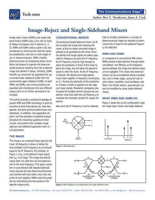
THE IMAGE<br />
The image is an unwanted input signal to the<br />
mixer. Its frequency is above or below the<br />
local oscillator (LO) frequency by an amount<br />
equal to the IF frequency. For example, in<br />
Figure 1, if fR1 is the desired if input signal,<br />
then fR2 is its image. The image <strong>and</strong> desired<br />
inputs both mix with the LO <strong>and</strong> downconvert<br />
to the same frequency. This poses a problem<br />
in conventional DB (double-balanced)<br />
mixers because the two downconverted products<br />
interfere with each other, since they exit<br />
at the IF port together. IRMs avoid this problem<br />
by channelizing the two products into<br />
separate output ports.<br />
CONVENTIONAL MIXERS<br />
Conventional double-balanced mixers use filters<br />
to block the image from entering the<br />
mixer, so that no down-converted image is<br />
allowed to be generated by the mixer. Since<br />
the desired <strong>and</strong> image signals are always separated<br />
in frequency by twice the IF frequency,<br />
the IF frequency must be high enough to<br />
allow the preselector in front of the mixer to<br />
block the image, but still allow the desired if<br />
signal to enter the mixer. As the IF frequency<br />
is reduced, the desired <strong>and</strong> image signals<br />
move closer together in frequency (converging<br />
on fL), forcing the selectivity of the preselector<br />
to increase in order to separate the two adjacent<br />
input signals. Preselector complexity also<br />
increases for tunable receivers because the preselector<br />
must track with the LO frequency, to<br />
maintain the normally constant IF output frequency.<br />
Also since the IF frequency must be relatively<br />
RF<br />
INPUT<br />
R<br />
Figure 1. IRM application.<br />
RF<br />
50Ω<br />
90° LO 90°<br />
RF<br />
QUADRATURE<br />
HYBRID<br />
I2' IF<br />
QUADRATURE<br />
HYBRID<br />
WJ Communications, Inc. • 401 River Oaks Parkway • San Jose, CA 95134-1918 • Phone: 1-800-WJ1-4401 • Fax: 408-577-6620 • e-mail: sales@wj.com • Web site: www.wj.com<br />
L<br />
LO<br />
INPUT<br />
I1<br />
I2<br />
Figure 2. Block diagram of an image-reject <strong>and</strong> single-sideb<strong>and</strong> mixer.<br />
0°<br />
I1<br />
I2<br />
M1<br />
M2<br />
high to simplify preselection, a number of<br />
downconversion stages are required to downconvert<br />
the rf input to the baseb<strong>and</strong> frequency<br />
for detection.<br />
IRMS AND SSMS<br />
In comparison to conventional DB mixers,<br />
IRMs achieve image-rejection through phase<br />
cancellation, not filtering, so the frequency<br />
spacing between the image <strong>and</strong> desired inputs<br />
can be negligible. This means that downconversion<br />
can be accomplished without preselection,<br />
<strong>and</strong> in fewer stages, saving the cost of<br />
extra mixers, amplifiers, local oscillators, <strong>and</strong><br />
fitters. For similar reasons, upconversion can<br />
also be simplified by using single-sideb<strong>and</strong><br />
mixers.<br />
WHAT IRMS AND SSMS DO<br />
Figure 2 shows the circuit configuration used<br />
for image-reject mixers <strong>and</strong> single-sideb<strong>and</strong><br />
f1<br />
OUTPUT<br />
I1'<br />
0°<br />
fR1 fL fR2<br />
INPUTS<br />
I1<br />
I2
Tech-note<br />
mixers. The only differences between them<br />
are their respective applications <strong>and</strong> parameters.<br />
IRM<br />
Figure 1 shows how the circuit of Figure 2 is<br />
operated as an IRM. The signal at fR1 will<br />
downconvert to exit at I1, <strong>and</strong> the signal at<br />
fR2 will down-convert to exit at I2. If fR1 is<br />
the desired signal, then fR2 is its image.<br />
Ideally, none of the downconverted image signal<br />
exits the desired IF output port. However,<br />
since amplitude <strong>and</strong> phase imbalances exist in<br />
practical circuits, some of the downconverted<br />
image will be present at the desired IF output<br />
port. <strong>Image</strong> rejection is defined as the ratio of<br />
the downconverted image signal power exiting<br />
the desired IF port, to that of the desired<br />
signal, exiting the same IF output port. For<br />
example, if the downconverted image <strong>and</strong><br />
desired signal levels at I 1 are -30 dBm <strong>and</strong><br />
-10 dBm respectively, then the image rejection<br />
is 20 dB. Good image rejection requires<br />
close amplitude <strong>and</strong> phase matching, low<br />
mixer VSWR, <strong>and</strong> directivity.<br />
SSM<br />
Figure 3 shows how the circuit of Figure 2 is<br />
operated as a single-sideb<strong>and</strong> mixer. The SSM<br />
provides a single-sideb<strong>and</strong> suppressed carrier<br />
output. A LSB or USB output can be selected<br />
by choosing which I port to drive with the IF<br />
signal. An IF into I1, results in an LSB output,<br />
<strong>and</strong> an input into I2, results in a USB<br />
output. SSMs have two main parameters:<br />
sideb<strong>and</strong> suppression <strong>and</strong> carrier suppression.<br />
Sideb<strong>and</strong> suppression is analogous to image<br />
rejection, <strong>and</strong> is defined as the ratio of the<br />
undesired sideb<strong>and</strong> signal power to that of the<br />
desired sideb<strong>and</strong> signal power at the if output<br />
port. Carrier suppression is a measure of how<br />
much of the carrier signal leaks through the<br />
SSM to become present at the rf output, <strong>and</strong><br />
is defined as the ratio of the carrier-power<br />
level at the output port to that of the desired<br />
output-power level at the if output port.<br />
Both sideb<strong>and</strong> <strong>and</strong> carrier suppression are<br />
specified in terms of dBc because they are<br />
measured with respect to the desired LSB or<br />
USB output-power level.<br />
HOW IRMS AND SSMS OPERATE<br />
<strong>Image</strong>-reject <strong>and</strong> single-sideb<strong>and</strong> mixer operation<br />
may be explained as follows: In any<br />
mixer, the phase angles of its rf <strong>and</strong> LO input<br />
signals are conserved through the mixing<br />
process, so that the phase of the IF output<br />
equals the sum of the if <strong>and</strong> LO input phase<br />
angles, multiplied by their respective harmonic<br />
coefficients, m <strong>and</strong> n. These coefficients<br />
define the inter-modulation products exiting<br />
the mixer fIM = mfR + nfL, where m <strong>and</strong> n are<br />
positive or negative integers. For the desired<br />
<strong>and</strong> image downconverted products, m <strong>and</strong> n<br />
equal ±1. For example, referring to Figure 1,<br />
if the frequency of the downconverted desired<br />
signal is fIF = fL - fR1, then n = 1 <strong>and</strong> m = -1,<br />
<strong>and</strong> its phase angle will equal (θL - θR1 ),<br />
where θL <strong>and</strong> θR1 are the phase angles of the<br />
LO <strong>and</strong> rf inputs, respectively. Similarly, the<br />
frequency of the downconverted image signal<br />
is fIM = fR2 - fL so that m = 1 <strong>and</strong> n = -1, <strong>and</strong><br />
its phase angle equals (θR2 - θL). Figure 2 shows that both IRMs <strong>and</strong> SSMs<br />
comprise two mixers, two quadrature power<br />
dividers, <strong>and</strong> one in-phase power divider.<br />
These are all passive devices, <strong>and</strong> can act<br />
together to significantly enhance system costeffectiveness,<br />
performance, <strong>and</strong> reliability.<br />
<strong>Mixers</strong> M1 <strong>and</strong> M2 have IF output currents,<br />
fC<br />
Figure 3. SSM application.<br />
The Communications Edge <br />
Author: Bert C. Henderson, James A. Cook<br />
RF<br />
OUTPUT<br />
I1’ <strong>and</strong> I2’, respectively. The phase angles of I1’ <strong>and</strong> I2’ are 0° <strong>and</strong> 90°, respectively. For both<br />
mixers, ( θL is set equal to zero because the LO<br />
is applied in-phase to M1 <strong>and</strong> M2. Also,<br />
since the IF inputs to M1 <strong>and</strong> M2 are in<br />
quadrature; i.e., 90° out of phase with respect<br />
to each other, (θR for M1 is set equal to zero,<br />
<strong>and</strong> (θR for M2 is set equal to 90°. Hence, 1’ I<br />
= Imn∠0° <strong>and</strong> I2’ = Imn∠m90°. Imn is the<br />
same for M1 <strong>and</strong> M2 because the two mixers<br />
are assumed to have matching conversion-loss<br />
characteristics.<br />
I 1’ <strong>and</strong> I 2’ combine in the output quadrature<br />
power divider in such a way as to channelize<br />
the (f L - f R1) product into output port I 1, <strong>and</strong><br />
the (f R2 - f L) product into output port I 2.<br />
When downconverting, one product is taken<br />
to be the desired output, <strong>and</strong> the other is<br />
taken to be the image output, which is terminated.<br />
The following shows how this channelization<br />
occurs:<br />
I1 = 1/2 (I1’ + I2’ ∠90°)<br />
= 1/2 (Imn + Imn ∠(m + 1) 90°)<br />
Imn ; m = -1(fL - f<br />
=<br />
R1)<br />
{ 0 ; m = 1(fR2 - fL) (1)<br />
I2 = 1/2 (I1’ ∠90° + I2’ )<br />
= 1/2 (Imn∠90° + Imn∠m90°) 0 ; m = -1(fL - f<br />
= R1)<br />
{<br />
Imn∠90° ; m = 1(fR2 - fL) (2)<br />
WJ Communications, Inc. • 401 River Oaks Parkway • San Jose, CA 95134-1918 • Phone: 1-800-WJ1-4401 • Fax: 408-577-6620 • e-mail: sales@wj.com • Web site: www.wj.com<br />
L<br />
I2<br />
f1<br />
I1<br />
R<br />
f1<br />
INPUT<br />
f1<br />
INPUT<br />
I1 AS INPUT<br />
I2 AS INPUT<br />
L<br />
S<br />
B<br />
fc<br />
U<br />
SB<br />
OUTPUTS<br />
L<br />
S<br />
B<br />
fc<br />
U<br />
SB<br />
OUTPUTS
Tech-note<br />
When upconverting, I 1 <strong>and</strong> R 1 are interchanged,<br />
as are I 2 <strong>and</strong> R 2, so that the inputs<br />
to the mixer are a low-frequency signal injected<br />
at I 1 <strong>and</strong> I 2, <strong>and</strong> a microwave carrier<br />
injected at the LO port. The outputs are the<br />
LSB (f L - f I1) product that exits at R 1, <strong>and</strong> the<br />
USB (f L + f I2) product that exits at R 2.<br />
PRACTICAL PERFORMANCE<br />
CONSIDERATIONS<br />
The conversion loss of an IRM includes the<br />
losses due to the quadrature hybrids <strong>and</strong> inphase<br />
power splitter, in addition to the mixer<br />
conversion loss. This additional circuitry<br />
increases the conversion loss, but not to unacceptable<br />
levels. Figure 4 shows the typical<br />
conversion loss of an IRM <strong>and</strong> a SSM.<br />
Typical conversion loss is 8.0 dB from 8 to<br />
18 GHz.<br />
The amount of image rejection obtained with<br />
an IRM is determined by the circuit amplitude<br />
<strong>and</strong> phase balance. Since circuitry imbalances<br />
are frequency dependent, image rejection<br />
is also frequency dependent. Figure 5<br />
shows the frequency dependence of the image<br />
rejection for the IRM <strong>and</strong> the sideb<strong>and</strong> suppression<br />
for the SSM, typical performance<br />
being 22 dB.<br />
Intermodulation products are more critical for<br />
the SSM, since there are several spurious<br />
products close to the desired output [4].<br />
Suppression of the carrier signal, at frequency<br />
f c, is also important. Figure 6 shows the typical<br />
output spectra for two different applications<br />
of the SSM.<br />
Figure 6A shows the SSM using the low-frequency<br />
f IF signal as the high-power input, <strong>and</strong><br />
Figure 6B shows the SSM with the high-frequency<br />
f c signal as the high-power input.<br />
Inspection of Figure 6 reveals the trade-off<br />
between the two different applications. A<br />
high-level f c signal provides good inter-modulation<br />
suppression, but poor carrier suppression;<br />
whereas, a high-level f IF signal provides<br />
good carrier suppression at the expense of<br />
reduced intermodulation suppression. The<br />
carrier suppression is determined by the mixer<br />
L-R isolation.<br />
Also, suppression of the 1 × 3 product is not<br />
the same for f c - 3f I, as it is for f c + 3f I. The<br />
CONVERSION LOSS (dB)<br />
CONVERSION LOSS (dB)<br />
IMAGE REJECTION (dB)<br />
SIDEBAND SUPPRESSION (dB)<br />
5<br />
6<br />
7<br />
8<br />
9<br />
8<br />
5<br />
6<br />
7<br />
8<br />
9<br />
8<br />
Figure 4. Conversion-loss.<br />
10<br />
15<br />
20<br />
25<br />
30<br />
8<br />
10<br />
15<br />
20<br />
25<br />
30<br />
8<br />
Figure 5. <strong>Image</strong>-rejection <strong>and</strong> sideb<strong>and</strong> suppression.<br />
The Communications Edge <br />
Author: Bert C. Henderson, James A. Cook<br />
1 × 3 product closest to the desired output is<br />
always suppressed more than the 1 × 3 prod-<br />
uct closest to the undesired output. This<br />
additional suppression is caused by the input<br />
9 10 11 12 13 14 15 16 17 18<br />
FREQUENCY (GHz)<br />
A. Conversion-loss of the M34C single-sideb<strong>and</strong> mixer.<br />
9 10 11 12 13 14 15 16 17 18<br />
FREQUENCY (GHz)<br />
B. Conversion-loss of the M33C image-reject mixer.<br />
9 10 11 12 13 14 15 16 17 18<br />
FREQUENCY (GHz)<br />
A. M33C image-rejection.<br />
9 10 11 12 13 14 15 16 17 18<br />
FREQUENCY (GHz)<br />
B. M34C sideb<strong>and</strong> suppression.<br />
WJ Communications, Inc. • 401 River Oaks Parkway • San Jose, CA 95134-1918 • Phone: 1-800-WJ1-4401 • Fax: 408-577-6620 • e-mail: sales@wj.com • Web site: www.wj.com
Tech-note<br />
<strong>and</strong> output quadrature couplers. In fact, every<br />
other odd harmonic from the undesired sideb<strong>and</strong><br />
exhibits this characteristic.<br />
APPENDIX A:<br />
SIMPLIFIED ANALYSIS OF<br />
QUADRATURE MIXERS<br />
This analysis shows which mixing products<br />
will exit the various ports of a quadrature<br />
mixer. Much of this analysis has already been<br />
published [1, 5], but without the mathematical<br />
simplifications included here. The<br />
SUPPRESSION (dB)<br />
SUPPRESSION (dB)<br />
0<br />
10<br />
20<br />
30<br />
40<br />
50<br />
60<br />
0<br />
10<br />
20<br />
30<br />
40<br />
50<br />
60<br />
Figure 6. Intermodulation suppression.<br />
approach is to determine the Fourier series for<br />
the current in each mixer diode, then sum<br />
these currents to determine which mixing<br />
products exit the various ports.<br />
For example, the IRM of Figure 7 is analyzed.<br />
The current in each diode is assumed to flow<br />
from anode to cathode, <strong>and</strong> is written as a<br />
double Fourier series:<br />
iD = Σ Σ gn vm ej(nωL + mωR )t ejmφ ejnθ ∞ ∞<br />
n=1 m=1<br />
= k nm e jmφ e jnθ<br />
This double series results from multiplying<br />
1 × 3 1 × 2 LSB fC USB 1 × 2 1 × 3<br />
A. I-port input power = +10 dBm.<br />
1 × 3 1 × 2 LSB fC USB 1 × 2 1 × 3<br />
B. R-port input power = +10 dBm.<br />
The Communications Edge <br />
Author: Bert C. Henderson, James A. Cook<br />
the diode conductance waveform, which is<br />
governed by the LO signal, by the waveform<br />
for the voltage across the diode, which is governed<br />
by the if signal. The amplitude portion<br />
of the Fourier series can be reduced to Knm,<br />
or K for short, since we are only concerned<br />
with phase.<br />
The phase angle θ corresponds to the difference<br />
in phase between the LO input <strong>and</strong> each<br />
of the diode currents. The phase angle φ corresponds<br />
to the difference in phase between<br />
the rf input <strong>and</strong> each of the diode currents.<br />
Four assumptions are made in this analysis:<br />
1. Perfect circuit balance <strong>and</strong> perfect<br />
quadrature couplers<br />
2. Identical diodes<br />
3. Large-signal LO<br />
4. Small-signal rf.<br />
The current in diode 1 can be written as:<br />
i 1 = K e jmπ = K (-1) m<br />
φ equals π because the if signal is 180° out of<br />
WJ Communications, Inc. • 401 River Oaks Parkway • San Jose, CA 95134-1918 • Phone: 1-800-WJ1-4401 • Fax: 408-577-6620 • e-mail: sales@wj.com • Web site: www.wj.com<br />
LO<br />
0°<br />
I1<br />
90°<br />
I2<br />
LPF LPF<br />
HPF HPF<br />
RF<br />
1 4<br />
2 3<br />
50Ω<br />
Figure 7. Schematic diagram of the image-reject mixer.
Tech-note<br />
phase with the assumed direction of currentflow<br />
in diode 1 (anode-to-cathode). θ equals<br />
zero because the LO signal is in phase with<br />
the current-flow in diode 1. The current in<br />
diode 2 can be written as:<br />
i 2 = K<br />
Both φ <strong>and</strong> θ equal zero because the rf <strong>and</strong><br />
LO inputs are in phase with the current-flow<br />
in diode 2. The current in diode 3 can be<br />
written as:<br />
i 3 = K e jm(π/2+π) e jnπ = Kj (-m) (-1) n<br />
φ equals (π/2 + π): The π/2 comes from the<br />
rf quadrature-hybrid, <strong>and</strong> the θ comes from<br />
the current flow in diode 3 being 180° out of<br />
phase with the rf signal exiting the hybrid.<br />
The current in diode 4 can be written as:<br />
i 4 = K e jmπ/2 e jnπ = Kj m (-1) n<br />
φ equals π/2 because of the rf quadrature<br />
hybrid, <strong>and</strong> θ equals π because the LO signal<br />
is 180° out of phase with the current flow in<br />
diode 4.<br />
Once the four individual diode currents have<br />
been determined, they can be combined to<br />
form the IF outputs at I 1 <strong>and</strong> I 2. The current<br />
exiting I 1 can be written as:<br />
iI1 = i1 - i2 + j i3 - j i4 = K [(-1) m -1 + j (1-m)(-1) n - j (1+m)(-1) n]<br />
Currents i 3 <strong>and</strong> i 4 are multiplied by j because<br />
of the 90° phase shift in the IF quadrature<br />
coupler. Currents i 2 <strong>and</strong> i 4 are negative<br />
because they are entering (instead of exiting)<br />
at the node connecting the diodes to the IF<br />
coupler. Similarly, the current exiting I 2 can<br />
be written as:<br />
iI2 = j i1 - j i2 + i3 - i4 = K [j(-1) m -j + j-m(-1) n - jm(-1) n]<br />
Table 1 summarizes which mixing products<br />
exit at I 1 <strong>and</strong> I 2. Notice first that the R±L<br />
products exit at I 1, <strong>and</strong> the L-R product exits<br />
at I 2 Also, notice that every other odd product<br />
exits I 1 <strong>and</strong> I 2. Mixing products (±L+R),<br />
(±L+5R), (±L+9R), etc. <strong>and</strong> (L-3R), (L-7R),<br />
(L-11R), all exit at I 1. And mixing products<br />
(L-R), (L-5R), (L-9R), etc., <strong>and</strong> (L+3R),<br />
(L+7R), etc., all exit at I 2. Finally, notice that<br />
the products exiting at I 1 <strong>and</strong> I 2 are always in<br />
quadrature with each other. When analyzing<br />
IM suppression, the b<strong>and</strong>width of the output<br />
port must be considered because many of the<br />
products in Table 1 could be outside the frequency<br />
range of the low-pass IF output.<br />
The preceeding analysis can be used to quickly<br />
analyze mixer/quadrature-hybrid networks<br />
to determine which products will exit the<br />
mixer ports. The phase angle of each diode<br />
current can be written in its final form in<br />
terms of j m, j n, (-1) m, (-1) n by inspection, <strong>and</strong><br />
then summed. A simple table of output products<br />
can then be written.<br />
APPENDIX B:<br />
IMAGE REJECTION AS A<br />
FUNCTION OF AMPLITUDE AND<br />
PHASE MATCH<br />
This analysis shows the relationship between<br />
image rejection <strong>and</strong> amplitude phase imbalances<br />
[6]. <strong>Image</strong> rejection is defined as the<br />
ratio of the magnitude of the image signal<br />
<strong>and</strong> the desired signal. Therefore, the image<br />
rejection at I1 in Figure 2 is:<br />
The Communications Edge <br />
Author: Bert C. Henderson, James A. Cook<br />
|I1(m=+1)| IR = -20 log<br />
|I1(m=-1)| (3)<br />
From equation (1) |I 1’| = |I 2’| = I mn; using this<br />
<strong>and</strong> rewriting equation (1), we obtain:<br />
I1 = 1/2 [|I1’| ∠θ1 + |I2’| ∠(θ2 + (m+1) 90°)]<br />
(4)<br />
From equation (4) we obtain the following<br />
equations for I1(m=+1) <strong>and</strong> I1(m=-l): I 1(m=+1) = 1/2 (|I 1’| ∠θ 1 - |I 2’| ∠θ 2)<br />
I 1(m=-1) = 1/2 (|I 1’| ∠θ 1 + |I 2’| ∠θ 2)<br />
For practical applications, I 1’ <strong>and</strong> I 2’ are not<br />
exactly amplitude <strong>and</strong> phase matched. If an<br />
amplitude imbalance factor of A <strong>and</strong> a phase<br />
imbalance factor of θ are included in equations<br />
(5A) <strong>and</strong> (5B), we obtain:<br />
I1(m=+1) = 1/2 [|I1’| ∠θ1] [(1 - A ∠θ2)] (6A)<br />
I1(m=-1) = 1/2 [|I1’| ∠θ1] [(1 + A ∠θ2)] (6B)<br />
Where,<br />
I<br />
A =<br />
2’<br />
<strong>and</strong> θ = θ2 - θ1 I1’ The factor A is equal to the sum of the individual<br />
amplitude imbalances in the rf <strong>and</strong> IF<br />
hybrids <strong>and</strong> the two mixers. The factor, θ, is<br />
Mixing Product (RF) m (LO) n I 1 I 2<br />
R+L 1 1 K[-1-1-1-1] = -4K K[-j-j+j+j] = 0<br />
R-L 1 -1 K[-1-1-1-1] = -4K K[-j-j+j+j] = 0<br />
L-R -1 1 K[-1-1+1+1] = 0 K[-j-j-j-j] = -4jK<br />
L to I isolation 0 1 K[-1-1-j+j] = 0 K[j-j-1+1] = 0<br />
R to I isolation 1 0 K[-1-1+1+1] = 0 K[j-j-j-j] = -4jK<br />
2x1 2 1 K[1-1+j-j] = 0 K[j-j+1-1] = 0<br />
-2x1 -2 1 K[1-1+j-j] = 0 K[j-j+1-1] = 0<br />
3x1 3 1 K[1-1+1+1] = 0 K[j-j-j-j] = -4jK<br />
-3x1 -3 1 K[1-1-1-1] = -4K K[j-j+j+j] = 0<br />
5x1 5 1 K[-1-1-1-1] = -4K K[-j-j+j+j] = 0<br />
-5x1 -5 1 K[-1-1+1+1] = 0 K[j-j-j-j] = -4jK<br />
Table 1. Summary of which mixing products exit I1 <strong>and</strong> I2. WJ Communications, Inc. • 401 River Oaks Parkway • San Jose, CA 95134-1918 • Phone: 1-800-WJ1-4401 • Fax: 408-577-6620 • e-mail: sales@wj.com • Web site: www.wj.com<br />
(5A)<br />
(5B)
Tech-note<br />
the total phase imbalance which is due to the<br />
sum of the deviation from quadrature in the<br />
rf <strong>and</strong> IF hybrids, <strong>and</strong> the phase imbalance of<br />
the two mixers.<br />
A <strong>and</strong> θ also include the effects of hybrid<br />
directivity <strong>and</strong> impedance mismatches<br />
between the hybrids <strong>and</strong> the mixers.<br />
Imperfect hybrid directivity causes additional<br />
phase errors, <strong>and</strong> impedance mismatches<br />
cause amplitude ripple [7].<br />
Substituting equations (5A) <strong>and</strong> (5B) into (3)<br />
results in the following equation for image<br />
rejection as a function of A <strong>and</strong> θ:<br />
1 + A2 - 2A cosθ<br />
IR = -10 log ( )<br />
A = 10<br />
1 + A 2 + 2A cosθ<br />
A dB -( 20 )<br />
The effect of A <strong>and</strong> θ on image rejection is<br />
illustrated in Figure 8 [6].<br />
Example: If the if hybrid amplitude imbalance<br />
is +0.5 dB, the IF hybrid amplitude<br />
imbalance is +0.5 dB, <strong>and</strong> the mixer amplitude<br />
match is -0.5 dB, the total amplitude<br />
imbalance is 0.5 + 0.5 - 0.5 = 0.5 dB. If the<br />
total phase imbalance is 10 degrees, the image<br />
rejection is 20.7 dB. This estimate of the<br />
image rejection is optimistic, since it does not<br />
include the effects of VSWR <strong>and</strong> imperfect<br />
hybrid directivity.<br />
CONCLUSION<br />
In summary, image-reject <strong>and</strong> single’ sideb<strong>and</strong><br />
mixers provide a valuable means of solving<br />
difficult system problems posed by conventional<br />
double-balanced mixers. Using phase<br />
cancellation instead of filtering for image<br />
rejection <strong>and</strong> sideb<strong>and</strong> suppression, fewer<br />
expensive components, such as mixers,<br />
VCOs, <strong>and</strong> amplifiers are required. This<br />
means that reliability is increased <strong>and</strong> cost is<br />
reduced. The theory <strong>and</strong> operation of IRMs<br />
<strong>and</strong> SSMs has been discussed, <strong>and</strong> key parameters<br />
have been defined. The tradeoffs<br />
between sideb<strong>and</strong>, inter-modulation <strong>and</strong> carrier<br />
suppression for upconverter applications<br />
are outlined, <strong>and</strong> practical design guidelines<br />
given. IRMs <strong>and</strong> SSMs are increasingly solving<br />
key system problems. It is the authors’<br />
intent that this article help further this<br />
progress.<br />
REFERENCES<br />
1. Cochrane, J. B. <strong>and</strong> F. A. Marki. ‘Thin-<br />
Film <strong>Mixers</strong> Team Up to Block Out<br />
<strong>Image</strong> Noise,” Microwaves, March 1977,<br />
Vol. 16, No. 3.<br />
2. Okean, H. C. <strong>and</strong> A. J. Kelly. “Low-Noise<br />
Receiver Design Trends Using State-ofthe-Art<br />
Building Blocks,” IEEE<br />
Transactions on Microwave Theory <strong>and</strong><br />
Techniques, April 1977, Vol. MTT25,<br />
No. 4, p. 256.<br />
3. Halford, B. R., “<strong>Single</strong>-Sideb<strong>and</strong> <strong>Mixers</strong><br />
IMAGE REJECTION (dB)<br />
50<br />
40<br />
30<br />
20<br />
10<br />
2°<br />
5°<br />
0.1°<br />
10°<br />
20°<br />
40°<br />
1°<br />
Figure 8. <strong>Image</strong> rejection vs. amplitude <strong>and</strong> phase imbalance.<br />
The Communications Edge <br />
Author: Bert C. Henderson, James A. Cook<br />
for Communication Systems,” 1982 IEEE<br />
MTT Symposium Digest, pp. 30-32.<br />
4. Giordano, M., et al. “SSB Modulators:<br />
Discrete or Integrate?” Microwaves,<br />
June 1979, p. 60.<br />
5. Henderson, B. C. ‘Mixer Design<br />
Considerations Improve Performance,”<br />
MSN, October 1981.<br />
6. Wilds, R. B. “Microwave Two-Phase<br />
Converters for <strong>Image</strong>less Receivers,”<br />
Microwave Journal, September 1961,<br />
Vol. 4, No. 9, pp. 84-87.<br />
7. Neuf, D. <strong>and</strong> S. Spohrer. “Conventional<br />
<strong>and</strong> New Applications for the Quadrature<br />
IF Microwave Mixer” Microwave Journal,<br />
January 1983, p. 103.<br />
0<br />
0 1 2 3 4 5 6 7 8 9 10<br />
AMPLITUDE IMBALANCE (dB)<br />
Copyright © 1985 Watkins-Johnson Company<br />
Vol. 12 No. 3 May/June 1985<br />
Revised <strong>and</strong> reprinted © 2001 WJ Communications, Inc.<br />
WJ Communications, Inc. • 401 River Oaks Parkway • San Jose, CA 95134-1918 • Phone: 1-800-WJ1-4401 • Fax: 408-577-6620 • e-mail: sales@wj.com • Web site: www.wj.com