HVHBT Doherty and Envelope Tracking PAs for High ... - TriQuint
HVHBT Doherty and Envelope Tracking PAs for High ... - TriQuint
HVHBT Doherty and Envelope Tracking PAs for High ... - TriQuint

Create successful ePaper yourself
Turn your PDF publications into a flip-book with our unique Google optimized e-Paper software.
<strong>HVHBT</strong> <strong>Doherty</strong> <strong>and</strong> <strong>Envelope</strong> <strong>Tracking</strong> <strong>PAs</strong> <strong>for</strong> <strong>High</strong> Efficiency<br />
WCDMA <strong>and</strong> WiMAX Basestation Applications<br />
Craig Steinbeiser, Thomas L<strong>and</strong>on, Gary Burgin, Oleh Krutko, Jeremy Haley, Preston Page,<br />
Don Kimball**, <strong>and</strong> Peter Asbeck**<br />
<strong>TriQuint</strong> Semiconductor, 500 W. Renner Road, Richardson, Texas 75080 USA<br />
**University of Cali<strong>for</strong>nia, San Diego, CA 92092 USA<br />
Abstract — <strong>HVHBT</strong> GaAs technology has been shown to be<br />
suitable <strong>for</strong> use in two leading power amplifier efficiency<br />
enhancement solutions: (1) <strong>Doherty</strong> <strong>and</strong> (2) <strong>Envelope</strong> <strong>Tracking</strong>.<br />
Each solution demonstrates the unique high efficiency<br />
characteristic of <strong>HVHBT</strong> GaAs technology. In both of these cases<br />
<strong>HVHBT</strong> GaAs has demonstrated highest efficiency among all<br />
evaluated technologies.<br />
In this paper we will compare <strong>Doherty</strong> <strong>and</strong> <strong>Envelope</strong> <strong>Tracking</strong><br />
solutions utilizing <strong>HVHBT</strong> technology. <strong>HVHBT</strong> results achieved<br />
in 2-way symmetric <strong>and</strong> asymmetric <strong>Doherty</strong> configurations are<br />
compared with recent <strong>Envelope</strong> <strong>Tracking</strong> (ET) results reported<br />
by researchers at UCSD. Although <strong>HVHBT</strong>/<strong>Doherty</strong> is very<br />
simple to implement, the advantages offered by <strong>HVHBT</strong>/ET<br />
including very high overall average-power PAE, increased<br />
available peak power, very low correction gain, wider tunable<br />
b<strong>and</strong>width, <strong>and</strong> improved thermal management together make<br />
<strong>HVHBT</strong>/ET solution a compelling alternative <strong>for</strong> high efficiency<br />
Power Amplifiers.<br />
Index Terms — GaAs <strong>HVHBT</strong>, <strong>Doherty</strong>, <strong>Envelope</strong> <strong>Tracking</strong>,<br />
efficiency, WCDMA, WiMAX, digital pre-distortion, power<br />
amplifier.<br />
I. INTRODUCTION<br />
On-going developments in <strong>High</strong> Voltage Heterojunction<br />
Bipolar Transistor (<strong>HVHBT</strong>) GaAs technology continue to<br />
enable significant advancement in WCDMA basestation RF<br />
power amplifier efficiency.<br />
<strong>High</strong> power-added-efficiency (PAE) is a key enabler <strong>for</strong><br />
modern basestation power amplifiers as system requirements<br />
drive toward use of higher peak to average ratio (PAR) signals<br />
in conjunction with limited available cooling <strong>and</strong> lower DC<br />
power consumption requirements. Achieving high averagepower<br />
PAE, while maintaining tight error vector magnitude<br />
(EVM) <strong>and</strong> ACLR specifications, is a challenge <strong>for</strong> high peak<br />
to average ratio WCDMA, WiMAX, <strong>and</strong> LTE signals.<br />
For the output stage, two leading efficiency enhancement<br />
solutions under evaluation are <strong>Doherty</strong> <strong>and</strong> <strong>Envelope</strong><br />
<strong>Tracking</strong> (ET). <strong>HVHBT</strong> technology is shown to be<br />
compatible with both efficiency enhancement solutions<br />
achieving very high efficiency, with <strong>HVHBT</strong>/ET showing the<br />
best overall PAE. GaAs <strong>HVHBT</strong>s are especially well suited<br />
<strong>for</strong> ET application since they can provide both high efficiency<br />
<strong>and</strong> gain over a wide dynamic range signal.<br />
In previous work [1] we presented a 2-way symmetrical<br />
250Wpk <strong>HVHBT</strong> <strong>Doherty</strong> that exhibits 57% collector<br />
efficiency (53% PAE) at 6dB backoff from P1dB <strong>and</strong> 62%<br />
collector efficiency (56% PAE) at 6dB backoff from Psat.<br />
Exceeding efficiency reported <strong>for</strong> LDMOS[2] <strong>and</strong> GaN[3].<br />
Recently we developed a 200Wpk <strong>HVHBT</strong> 2-way<br />
Asymmetric <strong>Doherty</strong> that shows 55% collector efficiency<br />
(49% PAE) at 9dB backoff from Psat surpassing results<br />
reported <strong>for</strong> a LDMOS Asymmetric <strong>Doherty</strong> [4] <strong>and</strong> a GaN<br />
symmetric <strong>Doherty</strong> with asymmetric drain bias [5] <strong>and</strong> much<br />
easier to implement compared to the novel 3-way mixedsignal<br />
<strong>Doherty</strong> proposed in [6]. The efficiency level of our<br />
asymmetric <strong>Doherty</strong> does not include mixed-signal techniques<br />
as used in [6] or asymmetric drain biasing as used in [5] <strong>and</strong><br />
there<strong>for</strong>e could be further improved, in an actual basestation<br />
system, if baseb<strong>and</strong> control of drive levels or asymmetric<br />
collector bias voltages is available.<br />
In our previous work [7], GaAs <strong>HVHBT</strong>s were evaluated in<br />
an <strong>Envelope</strong> <strong>Tracking</strong> amplifier configuration by researchers<br />
at UCSD, surpassing results reported <strong>for</strong> LDMOS[8][9][10]<br />
<strong>and</strong> GaN[11]. Measurements reported show that the overall<br />
system exceeds the linearity requirements <strong>for</strong> WCDMA <strong>and</strong><br />
WiMAX <strong>and</strong> achieves excellent overall efficiency (accounting<br />
<strong>for</strong> power dissipated by both the RF amplifier <strong>and</strong> the<br />
envelope amplifier).<br />
In this paper we will compare <strong>Doherty</strong> <strong>and</strong> <strong>Envelope</strong><br />
<strong>Tracking</strong> solutions implemented with <strong>HVHBT</strong> technology.<br />
<strong>HVHBT</strong> 2-way symmetric <strong>and</strong> Asymmetric <strong>Doherty</strong><br />
configurations are compared with recent <strong>HVHBT</strong> <strong>Envelope</strong><br />
<strong>Tracking</strong> results reported by researchers at UCSD. The 2-way<br />
<strong>HVHBT</strong>/<strong>Doherty</strong> is very simple to implement, however the<br />
advantages offered by <strong>HVHBT</strong>/ET including very high<br />
average power PAE, increased available peak power, very low<br />
correction gain, wider tunable b<strong>and</strong>width, <strong>and</strong> improved<br />
thermal management together make <strong>HVHBT</strong>/ET solution a<br />
compelling alternative <strong>for</strong> high efficiency power amplifiers.<br />
II. 2-WAY DOHERTY AMPLIFIER<br />
The 2-way <strong>Doherty</strong> amplifier is widely used in the industry<br />
today because it is very easy to implement, it is a drop-in<br />
replacement <strong>for</strong> class AB amplifier, <strong>and</strong> it is compatible with<br />
st<strong>and</strong>ard DPD techniques with no need <strong>for</strong> additional complex<br />
circuitry. However, since the efficiency boost of a <strong>Doherty</strong>
amplifier is due to load modulation of the carrier amplifier [1],<br />
the efficiency boost occurs across a relatively narrow b<strong>and</strong> <strong>and</strong><br />
is sensitive to variation in phase offsets. In addition, the RF<br />
load modulation is optimized to boost efficiency at a specific<br />
level of backoff. Operating beyond this backoff level<br />
efficiency decreases rapidly. For example a 2-way symmetric<br />
<strong>Doherty</strong> is optimized <strong>for</strong> operation through 6dB backoff while<br />
a 2-way 3dB-Asymmetric <strong>Doherty</strong> is designed to be operated a<br />
9dB backoff.<br />
<strong>HVHBT</strong> technology is well suited <strong>for</strong> <strong>Doherty</strong> operation<br />
due to very high efficiency at 2*Zopt <strong>for</strong> symmetric <strong>and</strong><br />
3*Zopt <strong>for</strong> 3dB-asymmetric load conditions where P1dB<br />
efficiency exceeds 75%, making a highly efficient carrier<br />
amplifier. In addition, the off-state impedance is very high,<br />
permitting the peaking amplifier to present a near ideal open at<br />
the combiner TEE <strong>for</strong> power levels at <strong>and</strong> below the target<br />
backoff. To explore the advantages of <strong>HVHBT</strong> technology,<br />
we developed a 2-way symmetric <strong>and</strong> a 2-way asymmetric<br />
<strong>Doherty</strong> amplifier using <strong>HVHBT</strong>-GEN1 technology.<br />
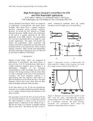
A. 2-Way Symmetric <strong>HVHBT</strong>/<strong>Doherty</strong> Amplifier<br />
A 2-way symmetric <strong>Doherty</strong> amplifier was designed to boost<br />
efficiency at 6dB Output-Back-Off from P1dB (OBO) [1].<br />
Gain Gain (dB) (dB)<br />
Fig. 1. 2-Way Symmetric <strong>Doherty</strong> (6dB Backoff Boost).<br />
15<br />
14<br />
13<br />
12<br />
11<br />
10<br />
9<br />
8<br />
7<br />
6<br />
5<br />
4<br />
3<br />
2<br />
1<br />
Gain_2140MHz_AB<br />
Gain_2140MHz<br />
Ceff_2140MHz_AB<br />
Ceff_2140MHz<br />
0<br />
0<br />
30 32 34 36 38 40 42 44 46 48 50 52 54<br />
Output Power (dBm)<br />
6dB Back-Off<br />
from P1dB<br />
Fig. 2. 2-Way Symmetric <strong>Doherty</strong> CW Pin/Pout<br />
75<br />
70<br />
65<br />
60<br />
55<br />
50<br />
45<br />
40<br />
35<br />
30<br />
25<br />
20<br />
15<br />
10<br />
5<br />
Collector Efficiency (%)<br />
2<br />
The <strong>Doherty</strong> amplifier is composed of a main amplifier <strong>and</strong> a<br />
peaking amplifier, where a 100W <strong>HVHBT</strong> module is used <strong>for</strong><br />
each shown in Figure 1.<br />
Figure 2 shows CW per<strong>for</strong>mance. CW saturated output<br />
power is 54dBm (250W) <strong>and</strong> P1dB at 53dBm (200W). At<br />
6dB OBO, output power is 47dBm (50W) <strong>and</strong> corresponding<br />
<strong>Doherty</strong> efficiency is greater than 57%.<br />
WCDMA linearity was characterized with a 2-carrier sideby-side<br />
WCDMA signal with 6.5dB PAR. Linearization was<br />
accomplished using a PALADIN®15 adaptive DPD test<br />
system, provided by PMC Sierra. Greater than 57% collector<br />
efficiency at 47dBm (50W) average output power has been<br />
demonstrated while achieving –55dBc linearized ACPR at<br />
5MHz offset. At this condition correction gain is near 3dB.<br />
B. 2-Way Asymmetric <strong>HVHBT</strong>/<strong>Doherty</strong> Amplifier<br />
A 2-way asymmetric <strong>Doherty</strong> amplifier was developed to<br />
boost efficiency at 9dB backoff <strong>for</strong>m P1dB [12]. The <strong>Doherty</strong><br />
amplifier consists of a 50W amplifier <strong>for</strong> the carrier amplifier<br />
<strong>and</strong> a 100W amplifier <strong>for</strong> the peaking amplifier shown in<br />
Figure 3. CW saturated power is greater than 200W (53dBm)<br />
<strong>and</strong> P1dB near 160W (52dBm). At 9dB backoff from P1dB,<br />
power is near 20W (43dBm) with collector efficiency near<br />
55% (48% PAE) at 2140MHz as shown in Figure 4.<br />
Fig. 3. 2-Way Asymmetric <strong>Doherty</strong> (9dB Backoff Boost) bed.<br />
Gain (dB)<br />
12<br />
11<br />
10<br />
9<br />
8<br />
7<br />
6<br />
5<br />
4<br />
3<br />
2<br />
1<br />
Gain<br />
CE<br />
PAE<br />
0<br />
10<br />
33 34 35 36 37 38 39 40 41 42 43 44 45 46 47 48 49 50 51 52 53<br />
Pout (dBm)<br />
9dB Back-Off<br />
from P1dB<br />
Fig. 4. 2-Way Asymmetric <strong>Doherty</strong> CW Pin/Pout<br />
70<br />
65<br />
60<br />
55<br />
50<br />
45<br />
40<br />
35<br />
30<br />
25<br />
20<br />
15<br />
Collector Efficiency (%)
III. ENVELOPE TRACKING AMPLIFIER<br />
Figure 5 shows a block diagram <strong>for</strong> an envelope tracking<br />
(ET) basestation amplifier. For envelope tracking (ET), the<br />
efficiency boost is achieved with DC bias modulation (as<br />
opposed to RF load modulation <strong>for</strong> the <strong>Doherty</strong>) effectively<br />
moving the efficiency boost operation into the baseb<strong>and</strong><br />
Fig. 5. Block diagram of envelope tracking basestation amplifier.<br />
electronics which simplifies the RF amplifier design to a class<br />
AB style topology, enabling high efficiency to be achieved<br />
across a broader b<strong>and</strong> (eliminating the b<strong>and</strong> limiting affect<br />
related to RF load modulation <strong>for</strong> the <strong>Doherty</strong>). The overall<br />
system <strong>for</strong> <strong>Envelope</strong> <strong>Tracking</strong> is more complex compared to<br />
that required <strong>for</strong> a <strong>Doherty</strong> PA. The ET PA requires a high<br />
current collector modulator, a separate DPD path <strong>for</strong> the<br />
modulator, <strong>and</strong> time alignment of the collector <strong>and</strong> RF signal.<br />
However, the advantages offered by <strong>HVHBT</strong>/ET including<br />
very high overall average-power PAE <strong>for</strong> a wide range of<br />
signal backoff, increased available peak power, very low<br />
correction gain, <strong>and</strong> improved thermal management together<br />
make <strong>HVHBT</strong>/ET solution a compelling alternative <strong>for</strong> high<br />
efficiency power amplifiers. Modulating the collector voltage<br />
to track the envelope of the wave<strong>for</strong>m greatly reduces power<br />
Signal Power (dBm)<br />
Fixed Supply Voltage (VCC = 28V)<br />
Peak Signal Power<br />
Average Signal Power<br />
Time (ns)<br />
Dissipated<br />
as heat.<br />
Transmitted<br />
Signal<br />
<strong>Envelope</strong><br />
Fig. 6. Illustration of regions of dissipated power <strong>for</strong><br />
fixed collector (left) <strong>and</strong> modulated collector (right).<br />
dissipated in the RF device as illustrated in Figure 6. To<br />
explore the suitability of <strong>HVHBT</strong> technology with envelope<br />
tracking, researchers at UCSD per<strong>for</strong>med the following study.<br />
A. <strong>HVHBT</strong>/ET Evaluation at UCSD<br />
Modulated Supply (3V to 30V)<br />
Time (ns)<br />
An <strong>HVHBT</strong>/ET amplifier was developed to boost efficiency<br />
<strong>for</strong> high PAR signals [7]. Testing was per<strong>for</strong>med using an<br />
envelope tracking test bed developed at the University of<br />
Cali<strong>for</strong>nia San Diego. Figure 7 shows a <strong>HVHBT</strong> amplifier colocated<br />
with the UCSD envelope amplifier. The 100W<br />
Signal Power (dBm)<br />
Peak Signal Power<br />
Average Signal Power<br />
Dissipated<br />
as heat.<br />
Transmitted<br />
Signal<br />
<strong>Envelope</strong><br />
3<br />
RF (out)<br />
Collector<br />
Voltage<br />
<strong>HVHBT</strong>-GEN1.5 device is mounted on a single ended class<br />
AB test fixture that has been optimized <strong>for</strong> power <strong>and</strong><br />
efficiency at a constant 28V collector bias. RF matching was<br />
not modified <strong>for</strong> ET operation, an area <strong>for</strong> future investigation<br />
<strong>and</strong> potential improvement. Baseb<strong>and</strong> envelope decoupling<br />
capacitors have been removed <strong>for</strong> compatibility with the<br />
envelope amplifier.<br />
The UCSD test bed utilized <strong>for</strong> this ef<strong>for</strong>t was optimized <strong>for</strong><br />
5MHz signals, with future development focused on exp<strong>and</strong>ing<br />
capability of the test bed to h<strong>and</strong>le 20MHz signals.<br />
Researchers at UCSD per<strong>for</strong>med all ET testing including<br />
linearization using digital predistortion. Measurement of the<br />
high voltage envelope amplifier used in this work shows<br />
efficiency of approximately 71% <strong>for</strong> a 1xWCDMA signal. At<br />
full output power, the peak output voltage of the modulator<br />
was set to 29V <strong>and</strong> the RMS voltage was 12.8V.<br />
B. <strong>HVHBT</strong>/ET Measurement Results<br />
Collector Modulator<br />
Fig. 7. <strong>HVHBT</strong> Test Fixture in UCSD ET test bed.<br />
The <strong>HVHBT</strong>/ET PA was evaluated using a variety of<br />
wave<strong>for</strong>ms including the UCSD benchmark single carrier<br />
WCDMA signal with 3.84 MHz b<strong>and</strong>width <strong>and</strong> peak-toaverage<br />
power ratio of 7.7dB.<br />
Figure 8 shows the measured AM-AM <strong>and</strong> AM-PM<br />
per<strong>for</strong>mance be<strong>for</strong>e pre-distortion, expressed in terms of the<br />
associated with AM/PM. The AM/AM characteristic is near<br />
ideal, a result of proper envelope tracking, suggesting DPD<br />
correction gain will be near 0dB. The scatter <strong>for</strong> the different<br />
values of input power indicates a modest memory effect <strong>and</strong><br />
phase distortion. These characteristics are a first indication<br />
that digital pre-distortion (DPD) should function well.<br />
Output WCDMA signal quality improves dramatically using<br />
DPD with memory mitigation. We observed greater than 57%<br />
PAE (including dissipation in both the RF amplifier <strong>and</strong> the<br />
envelope amplifier) at 45.2dBm (33.2W) average output<br />
power while achieving -70dBc linearized ACPR at a 5MHz<br />
offset using a single carrier WCDMA input signal with 7.7dB<br />
PAR measured at .01% on the CCDF. At this average power<br />
level, EVM measured to be 0.3% <strong>and</strong> correction gain was near<br />
0dB as expected. Average linearized power increased by<br />
1.2dB compared to constant collector operation.<br />
Figure 9 shows the measured instantaneous collector<br />
efficiency versus collector voltage after linearization. Notice<br />
collector efficiency is very flat <strong>and</strong> near 85% efficiency from<br />
7V to 29V. The output power tracks the square of the<br />
11.5Vdc<br />
12.8Vrm<br />
collector voltage <strong>and</strong> results in 85% collector efficiency over a<br />
12.5dB range, well in excess of the 6dB range <strong>for</strong> symmetric<br />
<strong>Doherty</strong> amplifiers <strong>and</strong> 9dB <strong>for</strong> an asymmetric <strong>Doherty</strong><br />
amplifier. This per<strong>for</strong>mance becomes especially important <strong>for</strong><br />
maintaining high efficiency in average power back-off.<br />
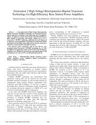
IV. <strong>HVHBT</strong>/ET VERSUS <strong>HVHBT</strong>/ DOHERTY<br />
195W<br />
Figure 10 illustrates a comparison of <strong>Envelope</strong> <strong>Tracking</strong> <strong>and</strong><br />
<strong>Doherty</strong> PA solutions implemented using <strong>HVHBT</strong>, GaN, <strong>and</strong><br />
LDMOS <strong>for</strong> a PA final stage. The point of comparison is<br />
achievable PAE versus signal PAR.<br />
First, let’s look only at <strong>HVHBT</strong> (highlighted in blue). The<br />
2-way symmetric <strong>Doherty</strong> is shown here with 53% PAE <strong>for</strong> a<br />
6.5dB PAR wave<strong>for</strong>m. The 2-way asymmetric <strong>Doherty</strong> is<br />
shown here at 49% PAE <strong>for</strong> 9.6dB PAR. Recall that these are<br />
two very different <strong>HVHBT</strong> <strong>Doherty</strong> designs, where the load<br />
modulation of each design is optimized to boost efficiency at a<br />
specific level of backoff. There<strong>for</strong>e when a basestation<br />
transmitter is designed using a <strong>Doherty</strong> final, there will be<br />
little flexibility in using higher PAR modulation schemes<br />
33W<br />
Fig. 9. Measured Power vs Instantaneous Collector<br />
Efficiency, 1xWCDMA 7.7dB PAR at 2140MHz<br />
4<br />
PAE (%)<br />
60<br />
50<br />
40<br />
<strong>HVHBT</strong> S-DTY<br />
WCDMA [1]<br />
LDMOS ET<br />
WCDMA [9] [10]<br />
GaN S-DTY<br />
WCDMA [3]<br />
LDMOS ET<br />
WCDMA [8]<br />
GaN ET<br />
WCDMA [11]<br />
<strong>HVHBT</strong> ET<br />
WCDMA [7]<br />
UCSD Benchmark<br />
Wave<strong>for</strong>m 7.7dB<br />
GaN ET<br />
WiMAX<br />
LDMOS S-DTY<br />
WCDMA [2]<br />
30<br />
6 6.5 7 7.5 8 8.5 9 9.5 10<br />
Peak to Average Ratio (dB)<br />
beyond the target backoff, without significantly degrading<br />
efficiency, necessitating a hardware modification.<br />
Also shown in blue is <strong>HVHBT</strong>/ET. In this case, only one<br />
<strong>HVHBT</strong>/ET amplifier was built. The blue line represents<br />
WCDMA results measured on the same <strong>HVHBT</strong>/ET amplifier<br />
using 4 different PAR signals. In addition, the same<br />
<strong>HVHBT</strong>/ET amplifier was evaluated with a 10MHz WiMAX<br />
signal at 2140MHz <strong>and</strong> reported as a solid blue circle. The<br />
small decrease in PAE is due to increased dissipation in the<br />
collector modulator. Notice that the same <strong>HVHBT</strong>/ET<br />
amplifier is capable of achieving better than 50% efficiency<br />
<strong>for</strong> signals PAR spanning 6.5dB through 9.6dB. This gives<br />
unprecedented flexibility to basestation hardware, enabling use<br />
of different modulation signals with different PAR <strong>for</strong> the<br />
same hardware with little impact on average power PAE.<br />
V. TECHNOLOGY COMPARISON<br />
<strong>HVHBT</strong> ET<br />
WiMAX [7]<br />
LDMOS A-DTY<br />
WCDMA [4]<br />
<strong>HVHBT</strong> A-DTY<br />
WCDMA<br />
GaN S-DTY<br />
Asym-Bias<br />
WCDMA [5]<br />
Fig. 10. PA final-stage efficiency versus signal PAR <strong>for</strong> <strong>HVHBT</strong>,<br />
LDMOS, <strong>and</strong> GaN in 2-Way <strong>Doherty</strong> <strong>and</strong> <strong>Envelope</strong> <strong>Tracking</strong><br />
configurations.<br />
Shown in Figure 10, is <strong>Envelope</strong> <strong>Tracking</strong> <strong>and</strong> <strong>Doherty</strong><br />
per<strong>for</strong>mance reported <strong>for</strong> <strong>HVHBT</strong>, GaN <strong>and</strong> LDMOS<br />
solutions. Comparing envelope tracking per<strong>for</strong>mance <strong>for</strong><br />
different device technologies is relatively easy since<br />
researchers at USCD have published evaluation results of<br />
several technologies measured under similar conditions, using<br />
the same bias modulator, same test set, <strong>and</strong> using the same<br />
benchmark 1xWCDMA wave<strong>for</strong>m with 7.7dB PAR.<br />
Reported WCDMA per<strong>for</strong>mance of various 2-Way <strong>Doherty</strong><br />
finals implemented with GaN <strong>and</strong> LDMOS are also shown in<br />
Figure 10. Please note that some small adjustments were<br />
applied in the case of [5] to convert from 50% drain efficiency<br />
to 46% PAE (we assumed 11dB gain). In the case of [3] we<br />
estimated the final stage efficiency by subtracting the reported<br />
driver dissipation <strong>and</strong> drive power from the overall lineup<br />
per<strong>for</strong>mance. For the various <strong>Doherty</strong> technologies in Figure<br />
10, the reported test signals, test conditions, linearization<br />
methods, <strong>and</strong> achieved linearity vary in each case. There<strong>for</strong>e,
an accurate benchmark <strong>for</strong> technology comparison of <strong>Doherty</strong><br />
amplifiers, similar to that offered by UCSD <strong>for</strong> envelope<br />
tracking amplifiers, is not presently available. As an example,<br />
<strong>for</strong> both of our reported <strong>Doherty</strong> amplifiers, a 5 point<br />
improvement in efficiency could be realized by reporting<br />
linearized efficiency at -50dBc instead of the reported -55dBc<br />
linearization level. Notice [2] <strong>and</strong> [3] report linearized<br />
efficiency at -50dBc. In addition there are other variables<br />
such as reporting efficiency versus signal crest factor as in the<br />
case of [6] or versus signal PAR which is more generally<br />
accepted as .01% probability on the CCDF. Also, in some<br />
cases, linearization is not applied, such as in [4] at -32dBc <strong>and</strong><br />
[5] at -38dBc, which is reasonable since predistortion<br />
technology is generally not a core competency of device<br />
providers.<br />
An alternate method of comparing <strong>Doherty</strong> efficiency would<br />
be to compare efficiency at a specific backoff level. However,<br />
the literature differs in reporting backoff from P1dB or<br />
backoff from Psat, <strong>and</strong> the measurement methods vary from<br />
CW (as in our case) to various <strong>for</strong>ms of pulsed RF. Also, in<br />
<strong>Doherty</strong>, it is well known that AM/AM <strong>and</strong> AM/PM, a key<br />
ingredient to linearization, can be traded <strong>for</strong> efficiency, yet<br />
another variable. There<strong>for</strong>e, accurate comparison of backoff<br />
efficiency is rather challenging. In our case, we report CW<br />
backoff per<strong>for</strong>mance after the PA has been adjusted <strong>for</strong> best<br />
linearization <strong>and</strong> verified using industry st<strong>and</strong>ard DPD.<br />
The <strong>TriQuint</strong> authors applaud UCSD <strong>for</strong> providing a<br />
relatively unambiguous method <strong>for</strong> comparing linearized<br />
device per<strong>for</strong>mance in an envelope tracking configuration.<br />
From the results reported in Figure 10, it is evident that<br />
<strong>HVHBT</strong> technology has demonstrated highest efficiency<br />
across a broad range of signal PAR when combined with<br />
<strong>Doherty</strong> <strong>and</strong> <strong>Envelope</strong> <strong>Tracking</strong> efficiency enhancement<br />
solutions <strong>for</strong> use in WCDMA, WiMAX, <strong>and</strong> LTE basestation<br />
applications.<br />
VI. SUMMARY AND CONCLUSIONS<br />
In this paper, we presented results <strong>for</strong> <strong>Doherty</strong> <strong>and</strong> envelope<br />
tracking power amplifiers using GaAs <strong>HVHBT</strong> technology.<br />
The symmetric <strong>Doherty</strong> is a relatively simple solution utilizing<br />
RF load modulation to achieve very high efficiency. Due to<br />
the characteristics of load modulation, the efficiency boost is<br />
b<strong>and</strong>-limited <strong>and</strong> sensitive to variation in the phase offsets,<br />
requiring each design to be optimized <strong>for</strong> a relatively narrow<br />
range of WCDMA signals. However, <strong>Doherty</strong> is widely used<br />
due to inherent simplicity. On the other h<strong>and</strong> envelope<br />
tracking utilizes collector voltage modulation to achieve high<br />
efficiency b operating the RF amplifier in saturation across a<br />
wide dynamic signal range. <strong>Envelope</strong> tracking is much more<br />
complex to implement compared to <strong>Doherty</strong>, requiring a<br />
collector voltage modulator, a separate DPD path <strong>for</strong> the<br />
modulator, <strong>and</strong> modulator timing alignment. However, as an<br />
advantage, this technique does not limit the b<strong>and</strong>width of the<br />
5<br />
RF amplifier, <strong>and</strong> a single design can achieve high PAE <strong>for</strong> a<br />
wide range of WCDMA <strong>and</strong> WiMAX signals.<br />
<strong>HVHBT</strong> has been shown to be compatible with both<br />
efficiency enhancement techniques, achieving impressive<br />
per<strong>for</strong>mance in each technique with envelope tracking<br />
achieving best overall per<strong>for</strong>mance.<br />
These results illustrate the potential of GaAs <strong>HVHBT</strong>s, in<br />
combination with advanced amplifier architectures, to achieve<br />
dramatic improvements in basestation power amplifiers.<br />
REFERENCES<br />
[1] Craig Steinbeiser, Thomas L<strong>and</strong>on, Charles Suckling, James<br />
Nelson, Joe Delaney, John Hitt, Larry Witkowski, Gary Burgin,<br />
Rached Hajji, <strong>and</strong> Oleh Krutko, “250W <strong>HVHBT</strong> <strong>Doherty</strong> with<br />
57% WCDMA Efficiency Linearized to –55dBc <strong>for</strong> 2c11 6.5dB<br />
PAR”, IEEE J. Solid-State Circuits, vol. 43, no. 10, pp. 2218-<br />
2228, Oct. 2008.<br />
[2] M. LeFevre, D. Runton, J. Kinney, J. Wright, J-C Nanan, J-J<br />
Bouny, “Digital Pre-Distortion Application of an LDMOS<br />
200W <strong>Doherty</strong> Amplifier”, IEEE Power Amplifier Symposium,<br />
Jan. 2006.<br />
[3] N. Ui, H. Sano, S. Sano, “A 80W 2-stage GaN HEMT <strong>Doherty</strong><br />
Amplifier with –50dBc ACLR, 42% Efficiency 32dB Gain with<br />
DPD <strong>for</strong> W-CDMA Base station”, IEEE Int. Microw. Symp.<br />
Dig., pp. 1259-1262, June 2007.<br />
[4] J. Gajadharsing, “Key Challenges Facing Basestation Power<br />
Amplifiers”, IWPC, 2007.<br />
[5] Yamamoto, T.; Kitahara, T.; Hiura, S., “50% Drain Efficiency<br />
<strong>Doherty</strong> Amplifier with Optimized Power Range <strong>for</strong> W-CDMA<br />
Signal”, IEEE Int. Microw. Symp. Dig, Page(s):1263 – 1266,<br />
June 2007.<br />
[6] Marco J. Pelk, W. C. Edmund Neo, John R. Gajadharsing,<br />
Raymond S. Pengelly, <strong>and</strong> Leo C. N. de Vreede, “A <strong>High</strong>-<br />
Efficiency 100-W GaN Three-Way <strong>Doherty</strong> Amplifier <strong>for</strong> Base-<br />
Station Applications”, IEEE Trans. Microw. Theory Tech, vol.<br />
56, no. 7, pp. 1582-1591, July 2008.<br />
[7] D. Kimball, M. Kwak, P. Draxler, J. Jeong, C. Hsia, C.<br />
Steinbeiser, T. L<strong>and</strong>on, O, Krutko, L. Larson, P. Asbek, “<strong>High</strong><br />
Efficiency WCMA <strong>Envelope</strong> <strong>Tracking</strong> Base-Station Amplifier<br />
Implemented with GaAs <strong>HVHBT</strong>s”, IEEE Compound<br />
Semiconductor Integr. Circuit Symp., Oct. 2008.<br />
[8] P. Draxler, S. Lanfranco, D. Kimball, C. Hsia, J. Jeong, J. Van<br />
de Sluis, <strong>and</strong> P.M. Asbeck, “<strong>High</strong> Efficiency <strong>Envelope</strong> <strong>Tracking</strong><br />
LDMOS Power amplifier <strong>for</strong> W-CDMA”, IEEE MTT-S Int.<br />
Microw. Symp. Dig., Jun. 2006, pp. 1534-1537.<br />
[9] C. Hsia, D. Kimball, P. Draxler, J.J. Yan, J. Kinney, E.<br />
Toulouse, J. Wood, <strong>and</strong> P.M. Asbeck, “<strong>High</strong> Efficiency<br />
<strong>Envelope</strong> <strong>Tracking</strong> Overdriven Class-A LDMOS Power<br />
Amplifier <strong>for</strong> Base Station Applications”, IEEE Power<br />
Amplifier Symposium, Jan. 2007.<br />
[10] Chin Hsia, D. Kimball, P. Draxler, J. J. Yan, P. M. Asbeck, J.<br />
Kinney, E. Toulouse, J. Wood, “<strong>High</strong> Efficiency LDMOS<br />
Power Amplifier <strong>for</strong> Wireless Base Stations Using <strong>Envelope</strong><br />
<strong>Tracking</strong>”, TECHCON, Nov. 2008.<br />
[11] Kimball, D.; Draxler, P.; Jeong, J.; Hsia, C.; Lanfranco, S.;<br />
Nagy, W.; Linthicum, K.; Larson, L.; Asbeck, P.;”50% PAE<br />
WCDMA base-station amplifier implemented with GaN<br />
HFETs”, IEEE Compound Semiconductor Integr. Circuit Symp.,<br />
pp. 1-4, Oct. 2005.<br />
[12] F.H.Raab, “Efficiency of <strong>Doherty</strong> RF power-amplifier systems,”<br />
IEEE Trans. Broadcast., vol.BC-33, no. 3, pp. 77-83, Sep.1987.