A2 35YHA1 - Hitachi Air Conditioning Products
A2 35YHA1 - Hitachi Air Conditioning Products
A2 35YHA1 - Hitachi Air Conditioning Products

You also want an ePaper? Increase the reach of your titles
YUMPU automatically turns print PDFs into web optimized ePapers that Google loves.
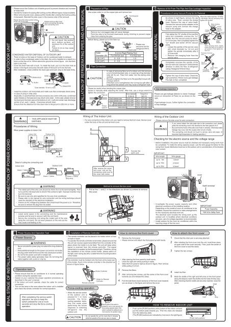
OUTDOOR UNITPlease mount the Outdoor unit of stable ground to prevent vibration and increaseof noise level.Decide the location for piping after sorting out the different types of pipe available.When removing side cover, please pull the handle after undoing the hook by pullingit downward. Reinstall the side cover in the reverse order of the removal.Please face this side (suction side)of the unit to the wall.CAUTIONDo not touch the suctionport, bottom surface, oraluminum fin of the outdoorunit.Failure to do so may causean injury.CONDENSED WATER DISPOSAL OF OUTDOOR UNITThere is holes on the base of Outdoor unit for condensed water to exhaust.In order to flow condensed water to the drain, the unit is installed on a stand or ablock so that the unit is 100mm above the ground as shown figure. Join the drainpipe to one hole.Cover the drain hole with a bush. To install the bush, put it on the drain hole asshown in the figure and press the both sides of the bush to fit into the hole.After installation, check whether the drain pipe and bush cling to the base firmly.PushPushDRAIN HOLE8 BUSHPlease remove side coverwhen connecting the pipingand connecting cord.Pull downwardBASEabove100mmDRAIN HOLEOuter diameter: 16 mm or more8 BUSH9 DRAIN PIPEInstall the outdoor unit horizontally and make sure that condensate drains away.In case of using in chilly areaEspecially, in case that there are many snows by very cold in chilly area, condensedwater freezes on the base and may result not to drain. In this case, please removethe bush and the drain pipe at the bottom of unit. (Left and center near dischargeportion of air, each 1 place). It becomes smooth drain.Ensure that the distance from the drain hole to the ground is 250 mm or more.INSTALLATION OF REFRIGERATING PIPES AND AIR REMOVAL1 Preparation of PipeUse a pipe cutter to cut the copper pipe and remove burr.CAUTIONRemove burr and jagged edge will cause leakage.Point the side to be trimmed downwards during trimming to prevent copperchips from entering the pipe.Before flaring, please put on the flare nut.OuterA (mm) Rigid Flaring ToolDiameter (Ø) For R410A tool For R22 tool6.35 (1/4") 0 - 0.5 1.09.52 (3/8") 0 - 0.5 1.02 Pipe ConnectionCAUTIONIn case of removing flare nut of a indoor unit, first removea nut of small diameter side, or a seal cap of big diameterside will fly out. Free from water into the piping whenworking.Be sure to tighten the flare nut to the specified torque witha torque wrench.If the flare nut is overtightened, the nut may be split after along period has passed, and may cause a refrigerant leak.Please be careful when bending the copper pipe.Screw in manually while adjusting the center. After that, use a torque wrench totighten the connection.Outer diameter Torque N·mFlare nutof pipe (ø)(kgf·cm)Small diameter side 6.35 (1/4") 13.7 – 18.6 (140 – 190)Large diameter side 9.52 (3/8") 34.3 – 44.1 (350 – 450)WrenchDieTorquewrenchCopper pipeDieTrimming toolA Please useexclusive tool forrefrigerant R410.Copper pipeValve Small diameter side 6.35 (1/4") 19.6 – 24.5 (200 – 250)head cap Large diameter side 9.52 (3/8") 19.6 – 24.5 (200 – 250)Valve core cap 12.3– 15.7 (125 – 160)3 Remove of <strong>Air</strong> From The Pipe And Gas Leakage InspectionAIR REMOVALProcedures of using Vacuum Pump for <strong>Air</strong> Removal1234As shown in right figure, remove the capof valve core. Then, connect the chargehose. Remove the cap of valve head.Connect the vacuum pump adapter to thevacuum pump and connect the chargehose to the adapter.Fully tighter the "Hi" shuttle of the manifoldvalve and completely unscrew the "Lo"shuttle. Run the vacuum pump for about10-15 minutes, then completely tighten the"Lo" shuttle and switch off the vacuumpump.Loosen the spindle of the service valvewith small diameter by 1/4 turn andtighten the spindle immediately after 5to 6 seconds.Remove the charging hose from theservice valve.Completely unscrew the spindle of theservice valve (at 2 places) in anticlockwisedirection to allow the flow of refrigerant(using Hexagonal Wrench key).Tighten the cap of valve head. Check thecap's periphery if there is any gas leakage.The task is then completed.Gas leakage inspectionPlease use gas leakage detector to check if leakageoccurs at connection of Flare nut as shown on theright.If gas leakage occurs, further tighten the connectionto stop leakage.When the meter reaches -101KPa(-76cmHg) during pumping fullytighten the shuttle.ValveChargehoseMeter showingpressureClosedR410AManifoldvalve VacuumpumpValveVacuumpumpadapterWhen pumping starts, slightlyloosen the flare nut to check ofair sucked in. Then tighten theflare nut.The body of servicevalveCap ofvalve coreHexagonalwrench KeyCap of valveheadCap of valveheadWARNINGProcedures of WiringWhen power supplies to Indoor UnitTHIS APPLIANCE MUST BEEARTHED.Indoor UnitOutdoor UnitWiring of The Indoor UnitFor wire connection of the Indoor unit, you need to remove the front cover, the low coverunder the body of the unit and terminal cover.DCWiring of the Outdoor UnitPlease remove the side cover for wire connection.WARNINGIf you cannot attach the side plate due to the connection cord, pleasepress the connecting cord in the direction to the front panel to fix it.Be sure that the hooks of the side cover fixed in certainly. Otherwise waterleakage may occur and this causes short circuit or faults.The connecting cord should not touch to service valve and pipes. (itbecomes high temperature in heating operation.)CONNECTION OF POWER CORDDetail of cutting the connecting cordIndoor UnitGreen + Yellow10mm70mm30mm10mmC D1.6 or2.0Connecting CordL N C D50mm10mmGreen + YellowWARNINGThe naked part of the wire core should be 10mm fix it to the terminal tightly. Thentry to pull the individual wire to check if the contact is tight. Improper insertion mayburn the terminal.Be sure to use only wire specified for the use of air-conditioner.Please refer to the manual for wire connection and the wiring technique shouldmeet the standard of the electrical installation.There is an AC voltage drop between the LN terminal if the power is on. Therefore,be sure to remove the plug from its socket.WARNINGConnecting CordLeave some space in the connecting cord for maintenancepurpose and be sure to secure it with the cord band.Secure the connecting cord along the coated part of the wireusing the cord band. Do not exert pressure on the wire as thismay cause overheating or fire.2.0AC 240VOutdoor Unit50mm10mmGreen + YellowStrip wiresAfter remove the screwand cover, and put theconnecting cords and fixthe cover with screw.Connect theearth cordMethod to remove the low coverPull at the 1 and 2 in the directions as shown by arrows to removethe cover.Checking for the electric source and the voltage rangeBefore installation, the power source must be checked and necessary wiring work mustbe completed. To make the wiring capacity proper, use the wire gauge list below for thewiring from house distribution fuse box to the outdoor unit in consideration of the blockedrotor current.IMPORTANTWire lengthWire gaugeup to 6m 1.6mm 2up to 15m 2.5mm 2up to 20m 4.0mm 2Investigate the power supply capacity and otherelectrical conditions at the installing location.Depending on the model of room air conditioner to beinstalled, request the customer to make arrangementsfor the necessary electrical work etc.The electrical work includes the wiring work up theoutdoor unit. In localities where electrical conditionsare poor, use of a voltage regulation is recommended.Install outdoor for the room air conditioner within thereaching range of the line cord.coverEarth terminalIMPORTANTFuse Capacity16A time delay fuseFINAL STAGE OF INSTALLATION1 Power Source And Operation TestPower SourceWARNINGNever remodel the power plug nor extend the long-distancecord.Keep additional length for the power cord and do not renderthe plug under external force as this may cause poor contact.Do not fix the power cord with U-shape nail.The power cable easily generates heat. Do not bring thecable together with a wire or vinyl tie.Operation testPlease ensure that the air conditioner is in normal operatingcondition during the operation test.Explain to your customer the proper operation procedures asdescribed in the user' s manual.If the indoor unit won't operate, check the cable for correctconnection.Turn on the lamp in the room where the indoor unit is installedand check the remote controller for normal operation.After completing the service switchoperation, be sure to keep theswitch pressed for one or moreseconds and stop the force-coolingoperation.2 Installation of Remote ControllerThe remote controller can be placed in its holder which is fixedon wall or beam.To operate the remote controller at its holder, please ensure thatthe unit can receive signal transmitted from the controller at theplace where the holder is to be fixed. The unit will beep whensignal is received from the remote controller. The signaltransmission is weaken by the fluorescent light. Therefore, duringthe installation of the remote control holder, please switch onthe light, even during day time, to determine the mounting locationof the holder.The controller must be hooked onto the hook at the lower partof the holder. Push in the remote controller in the direction asshown in figure below.Force-cooling operationWhen the service switchof the outdoor unit ispressed for 1 or moreseconds, the forcecoolingoperation starts.Use this mode whenperforming the failurediagnosis or collectingrefrigerant into theoutdoor unit.CAUTIONRemote controllerCoverScrewScrew (2 pieces)Holder for RemoteControllerService switch (If the switch ispressed for one or more seconds, theforce-cooling operation starts. If theswitch is pressed for additional one ormore seconds, the operation stops.)Do not operate the unit for more than 5 minuteswhile the spindle of the service valve is closed.How to remove the front cover1 Remove the front panelPlease remove and attach the front panel by both hands.After opening the front panel by both hands.1 Undo the right arm while pushing it inside.2 Slide the front panel to right as shown in figure. Then removewhile pulling it to front.2 Remove the filters.3 After removing two screws, pull the center of the front covertowards you and release the claws.4 Pull the side faces (lower sections) of the front cover towardsyou as shown in the figure and remove the cover.How to attach the front cover1 Check that the drain pan is securely attached.2 After installing the front cover onto the unit, hook three clawsat upper side of the cover securely. Then, push the center ofthe front cover to lock the claws.3 Tighten the two screws.HOW TO REMOVE INDOOR UNITPush up the [PUSH] sections at the bottom of the indoor unit andpull the bottom plate towards you. Then the claws are releasedfrom the stationary plate.(The [PUSH] sections are indicated by 2 arrows in the right figure)4 Install the filter.5 Slide the shafts of the right and left arms on the front panelalong the steps to insert the shafts into the holes till they stop.After checking that the shafts are securely inserted, close thepanel.ShaftHole[Push] mark positionsStep