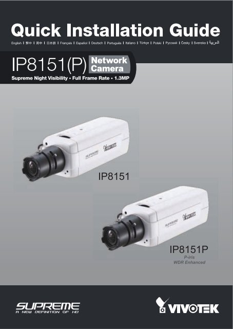
Vivotek IP8151 Quick Installation Guide
Vivotek IP8151 Quick Installation Guide
Vivotek IP8151 Quick Installation Guide
- No tags were found...

You also want an ePaper? Increase the reach of your titles
YUMPU automatically turns print PDFs into web optimized ePapers that Google loves.
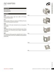
English1 Package Contents<strong>IP8151</strong> / <strong>IP8151</strong>PPower AdapterCamera StandCS-mount Lens<strong>Quick</strong> <strong>Installation</strong> <strong>Guide</strong>Software CDWarranty CardL-type Hex Key WrenchEN - 3
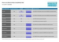
2 Physical DescriptionFront PanelLight SensorLensBuilt-in MicrophoneBack PanelStatus LEDAudio OutBNC Video OutMicrophone InExternal/InternalMIC SwitchEthernet 10/100RJ45 SocketRecessed ResetButtonLensSD/SDHC Card SlotNTSC/PAL SwitchPower Cord SocketGeneral I/OTerminal BlockFocus Assist Button (<strong>IP8151</strong>P only)DC-iris Control Cable Socket (<strong>IP8151</strong>)P-iris Control Cable Socket (<strong>IP8151</strong>P)Focus ControllerZoom ControllerEN - 4
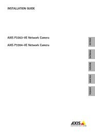
POWER COLLISION1 2 3 4 5LINKRECEIVEPARTITIONEnglish3 Mounting the Lens to the Camera1. Mount the lens by turning it clockwise onto the camera mount until it stops. Ifnecessary, turn the lens counterclockwise slowly until it gets the best attitude.2. Connect the DC-iris control cable to the socket. (<strong>IP8151</strong>)Connect the P-iris control cable to the socket. (<strong>IP8151</strong>P)12For further setup, please refer to the lens’ instruction manual inside thelens package.4 Network DeploymentGeneral Connection (without PoE)1. If you have external devices such as sensors and alarms, connect them to thegeneral I/O terminal block.2. Connect the camera to a switch via Ethernet cable.3. Connect the power cable from the Network Camera to a power outlet.3121: Power +12V2: Digital output3: Digital input4: Ground5: AC 24V6: AC 24V7: RS485+8: RS485-Ethernet SwitchEN - 5
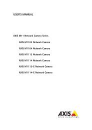
POWER COLLISION1 2 3 4 5LINKRECEIVEPARTITIONPOWER CO LISION1 2 3 4 5LINKRECEIVEPARTITIONPower over Ethernet (PoE)When using a PoE-enabled switchThe Network Camera is PoE-compliant, allowing transmission of power and data viaa single Ethernet cable. Follow the below illustration to connect the Network Camerato a PoE-enabled switch via Ethernet cable.PoE SwitchWhen using a non-PoE switchUse a PoE power injector (optional) to connect between the Network Camera and anon-PoE switch.PoE Power Injector(optional)Non-PoE SwitchEN - 6
English5 Assigning an IP Address1. Install "<strong>Installation</strong> Wizard 2" from the Software Utility directory on the software CD.2. The program will conduct an analysis of your network environment. After your networkis analyzed, please click on the "Next" button to continue the program.IW2<strong>Installation</strong>Wizard 23. The program will search for VIVOTEK Video Receivers, Video Servers, and NetworkCameras on the same LAN.4. After searching, the main installer window will pop up. Click on the MAC that matchesthe one labeled on the bottom of your device to connect to the Network Camera viaInternet Explorer.Network CameraModel No: <strong>IP8151</strong>P R o HSMAC:0002D173020200-02-D1-73-02-02 192.168.5.151 <strong>IP8151</strong>This device complies with part 15 of the FCC rules. Operation is subject to the following two conditions:(1)This device may not cause harmful interference, and(2) this device must accept any interference received, including interference that may cause undesired operation.Pat. 6,930,709Made in Taiwan0002D1730202EN - 7
6Ready to Use1. Access the Network Camera from the LAN.2. Retrieve live video through a web browser or recording software.3. Unscrew the zoom controller to adjust the zoom factor. Upon completion, tighten thezoom controller.4. Unscrew the focus controller to adjust the focus range. Upon completion, tighten thefocus controller.NT43∞WFor further setup, please refer to the user’s manual on the software CD.EN - 8