HW-D-0363 - STI - Specified Technologies Inc
HW-D-0363 - STI - Specified Technologies Inc
HW-D-0363 - STI - Specified Technologies Inc

Create successful ePaper yourself
Turn your PDF publications into a flip-book with our unique Google optimized e-Paper software.
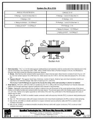
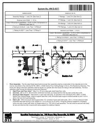
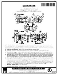
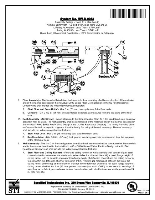
Assembly Ratings - 1 and 2 Hr (See Item 2)Nominal Joint Width - 1/2 and 3/4 in. (See Items 2A1 and 3)L Rating At Ambient - Less Than 1 CFM/Lin FtL Rating At 400°F - Less Than 1 CFM/Lin FtClass II and III Movement Capabilities - 100% Compression or ExtensionÌ78<strong>HW</strong>DÇ#_ÈAOÇ!+-`Î1. Floor Assembly - The fire-rated fluted steel deck/concrete floor assembly shall be constructed of the materialsand in the manner described in the individual D900 Series Floor-Ceiling Design in the UL Fire ResistanceDirectory and shall include the following construction features:A. Steel Floor and Form Units* - Max 3 in. (76 mm) deep galv steel fluted floor units.B. Concrete - Min 2-1/2 in. (64 mm) thick reinforced concrete, as measured from the top plane of the floorunits.1A. Roof Assembly - (Not Shown) - As an alternate to the floor assembly (Item 1), a fire rated fluted steel deck roofassembly may be used. The roof assembly shall be constructed of the materials and in the manner described inthe individual P900 Series Roof-Ceiling Design in the UL Fire Resistance Directory. The hourly fire rating of theroof assembly shall be equal to or greater than the hourly fire rating of the wall assembly. The roof assemblyshall include the following construction features:A. Steel Roof Deck - Max 3 in. (76 mm) deep galv steel fluted roof deck.B. Roof Insulation - Min 2-1/4 in. (57 mm) thick poured insulating concrete, as measured from the top planeof the steel roof deck.2. Wall Assembly - The 1 or 2 hr fire-rated gypsum board/stud wall assembly shall be constructed of the materialsand in the manner described in the individual U400 or V400 Series Wall or Partition Design in the UL FireResistance Directory and shall include the following construction features:A. Steel Floor and Ceiling Runners - Floor and ceiling runners of wall assembly shall consist of galv steelchannels sized to accommodate steel studs. When deflection channel (Item 3A) is used, flange height ofceiling runner is to be equal to or greater than flange height of deflection channel and the ceiling runner isto nest within the deflection channel with a min 3/4 in. (19 mm) gap maintained between the top of theceiling runner and the top of the deflection channel. When deflection channel is not used, flange height ofceiling runner shall be min 1 in. (25 mm) greater than nom joint width. Ceiling runner secured to valleys ofsteel floor or roof deck, perpendicular to steel deck direction, with steel fasteners or welds spaced max 24in. (610 mm) OC.Reproduced courtesy of Underwriters Laboratories, <strong>Inc</strong>.Created or Revised: January 11, 2011(800)992-1180 (908)526-8000 FAX (908)231-8415 E-Mail:techserv@stifirestop.com Website:www.stifirestop.comR<strong>HW</strong>-D-<strong>0363</strong>PAGE 1 OF 3
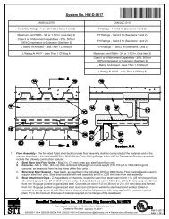
A1. Light Gauge Framing* - Slotted Ceiling Runner - As an alternate to the ceiling runner in Item 2A., slottedceiling runner to consist of galv steel channel with slotted flanges sized to accommodate steel studs (Item2B). Ceiling runner installed perpendicular to direction of fluted steel floor or roof deck and secured tovalleys with steel fasteners spaced max 24 in. (610 mm) OC. When slotted ceiling runner is used,deflection channel (Item 3A) shall not be used. Nominal joint size is 1/2 in. when slotted ceiling runner isused.CALIFORNIA EXPANDED METAL PRODUCTS CO - CSTBRADY CONSTRUCTION INNOVATIONS INC, DBA SLIPTRACK SYSTEMS - SLP-TRKMARINO/WARE, DIV OF WARE INDUSTRIES INC - Type SLTTHE STEEL NETWORK INC - VertiTrack VT, series,250VT, 362VT, 400VT, 600VT and 800VTA2. Light Gauge Framing* - Vertical Deflection Ceiling Runner - As an alternate to the ceiling runner inItems 2A and 2A1., vertical deflection ceiling runner to consist of galv steel channel with slotted verticaldeflection clips mechanically fastened within runner. Slotted clips, provided with step bushings, forpermanent fastening of steel studs. Vertical deflection ceiling runner installed perpendicular to direction offluted steel floor or roof deck and secured to valleys with steel fasteners spaced max 24 in. (610 mm) OC.When slotted ceiling runner is used, deflection channel (Item 3A) shall not be used.THE STEEL NETWORK INC - VertiTrack VTD362, VTD400, VTD600 and VTD800A3. Light Gauge Framing* - Slotted Ceiling Runner - As an alternate to the ceiling runner in Items 2A, 2A1,2A2 and 2A3, slotted ceiling runner to consist of galv steel channel with 3-1/4 in. (83 mm) high slottedflanges sized to accommodate steel studs (Item 2B). Ceiling runner installed perpendicular to direction offluted steel floor or roof deck and secured to valleys with steel fasteners spaced max 24 in. (610 mm) OC.When slotted ceiling runner is used, deflection channel (Item 3A) shall not be used.BRADY CONSTRUCTION INNOVATIONS INC, DBA SLIPTRACK SYSTEMS - SLPTRK325B. Studs - Steel studs to be min 3-1/2 in. (89 mm) wide. Studs cut min 3/4 in. (19 mm) less in length thanassembly height with bottom nesting in and secured to floor runner. When deflection channel (Item 3A) isused, steel studs attached to ceiling runner with sheet metal screws located 1 in. (25 mm) below the bottomof the deflection channel. When deflection channel is not used, studs to nest in ceiling runner withoutattachment. When slotted ceiling runner (Item 2A1) is used, steel studs secured to slotted ceiling runnerwith No. 8 by 1/2 in. (13 mm) long wafer head steel screws at midheight of slot on each side of wall. Whenvertical deflection ceiling runner (Item 2A2) is used, steel studs secured to slotted vertical deflection clips,through the bushings, with steel screws at midheight of each slot. Stud spacing not to exceed 24 in. (610mm) OC.C. Gypsum Board* - Gypsum board sheets installed to a min total thickness of 5/8 in. (16 mm) or 1-1/4 in.(32 mm) on each side of wall for 1 and 2 hr fire rated assemblies, respectively. Wall to be constructed inthe individual U400 or V400 Series Design in the UL Fire Resistance Directory, except that a max 3/4 in.(19 mm) gap shall be maintained between the top of the gypsum board and the bottom surface of the steelfloor or roof deck. The screws attaching the gypsum board to the studs along the top of the wall shall belocated 1 in. (25 mm) below the bottom of the ceiling runner. No gypsum board attachment screws shall bedriven into the ceiling runner or into the optional deflection channel.The hourly fire rating of the joint system is equal to the hourly fire rating of the wall.3. Joint System - Max separation between bottom of floor or roof deck and top of gypsum board (at time ofinstallation of joint system) is 3/4 in. (19 mm) or 1/2 in. (13 mm) when Item 2A1 is used. The joint systemis designed to accommodate a max 100 percent compression or extension from it's installed width. Thejoint system shall consist of forming and fill materials, with or without a deflection channel (Item 3A), as follows:A. Deflection Channel - (Optional, Not Shown)-Max 2 in. (51 mm) deep min 25 gauge galv steel channelsized to accommodate ceiling runner (Item 2A). Deflection channel secured to valleys of steel floor or roofdeck, perpendicular to steel deck direction, with steel fasteners or welds spaced max 24 in. (610 mm) OC.The ceiling runner is installed within the deflection channel to maintain a min 3/4 in. (19 mm) gap betweenthe top of the ceiling runner and the top of the deflection channel. The ceiling runner nests inside thedeflection channel without attachment.Reproduced courtesy of Underwriters Laboratories, <strong>Inc</strong>.Created or Revised: January 11, 2011(800)992-1180 (908)526-8000 FAX (908)231-8415 E-Mail:techserv@stifirestop.com Website:www.stifirestop.comR<strong>HW</strong>-D-<strong>0363</strong>PAGE 2 OF 3
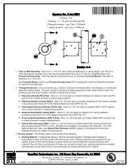
B. Forming Material* - Nom 4 pcf (64 kg/m3) mineral wool batt cut to the shape of the steel deck flute with aheight 1 in. (25 mm) greater greater than the overall thickness of the wall assembly. Mineral than height offlutes and with a length 3/4 to 1 in. (19 to 25 mm) wool batt compressed and installed into each flute abovethe ceiling runner with its ends projecting 3/8 to 1/2 in. (10 to 13 mm) beyond the wall surfaces.OWENS CORNING HT INC, DIV OF OWENS CORNING - Paroc Safing InsulationROCK WOOL MANUFACTURING CO - Delta BoardROCKWOOL MALAYSIA SDN BHD - SafeROXUL INC - SafeTHERMAFIBER INC - SAFC. Forming Material* - Nom 3/16 in. (4.8 mm) thick by 4 in. (102 mm) high joint forming material profileinstalled on both sides of the wall assembly. Profile installed by first marking a line across the top of thewall 3 in. (76 mm) below the bottom plane of the steel floor or roof deck valleys. Joint profile materialpositioned with its top edge against both the underside of the steel deck and the end of the mineral woolbatt plugs (Item 3B) and with its bottom edge on the line scribed on the wall assembly. Bottom of the jointprofile attached to gypsum board with nom 1/2 in. (13 mm) long steel staples spaced not greater than 8 in.(203 mm) OC. Adjoining lengths of profile to overlap approx 3/4 in. (19 mm) at shiplapped ends.SPECIFIED TECHNOLOGIES INC - SpecSeal Speed Flex Joint ProfileD. Fill, Void or Cavity Material* - Sealant - Min 1/8 in. (3.2 mm) wet thickness (min 1/16 in. or 1.6 mm drythickness) of fill material spray applied to completely cover forming materials on each side of the wall with amin 1/2 in. (13 mm) overlap onto gypsum board and steel deck on both sides of the wall.SPECIFIED TECHNOLOGIES INC - SpecSeal AS200 Elastomeric Spray*Bearing the UL Classification MarkReproduced courtesy of Underwriters Laboratories, <strong>Inc</strong>.Created or Revised: January 11, 2011(800)992-1180 (908)526-8000 FAX (908)231-8415 E-Mail:techserv@stifirestop.com Website:www.stifirestop.comR<strong>HW</strong>-D-<strong>0363</strong>PAGE 3 OF 3