Industrial P.O.E. Managed Ethernet Switch - Meridian Technologies
Industrial P.O.E. Managed Ethernet Switch - Meridian Technologies
Industrial P.O.E. Managed Ethernet Switch - Meridian Technologies

You also want an ePaper? Increase the reach of your titles
YUMPU automatically turns print PDFs into web optimized ePapers that Google loves.
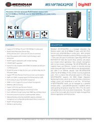
MS10FT8GX2POE | DigiNET<strong>Industrial</strong> P.O.E.<strong>Managed</strong> <strong>Ethernet</strong> <strong>Switch</strong>MS10FT8GX2POEUser’s ManualVersion 1.3April 2011<strong>Meridian</strong> <strong>Technologies</strong>, Inc., 700 Elmont Rd., Elmont, NY 11003Phone: +1 516-285-1000Fax: +1 516-285-6300Website: www.meridian-tech.comE-mail: support@meridian-tech.com
MS10FT8GX2POE User’s ManualTable of ContentGetting to Know Your <strong>Switch</strong> ........................................................................ 4 1.1 About the MS10FT8GX2POE <strong>Managed</strong> <strong>Industrial</strong> <strong>Switch</strong> ............................................... 4 1.2 Software Features ................................................................................................................... 4 1.3 Hardware Features ................................................................................................................. 5 Hardware Installation ...................................................................................... 6 2.1 Installing <strong>Switch</strong> on DIN-Rail (not included) ........................................................................ 6 2.1.1 Mount MS10FT8GX2POE on DIN-Rail ............................................................................ 6 2.2 Wall Mounting Installation ...................................................................................................... 6 2.2.1 Mount MS10FT8GX2POE on the wall .............................................................................. 6 Hardware Overview ......................................................................................... 8 3.1 Front Panel ............................................................................................................................... 8 3.2 Front Panel LEDs .................................................................................................................... 9 3.3 Top view Panel ...................................................................................................................... 10 3.4 Rear Panel .............................................................................................................................. 10 Cables ............................................................................................................ 11 4.1 <strong>Ethernet</strong> Cables ..................................................................................................................... 11 4.1.1 100BASE-TX/10BASE-T Pin Assignments ..................................................................... 11 4.2 SFP .......................................................................................................................................... 13 4.3 Console Cable ....................................................................................................................... 13 WEB Management ......................................................................................... 15 5.1 Configuration using the Web Browser ............................................................................... 15 5.1.1 About Web-based Management ........................................................................................ 15 5.1.2 System Information ........................................................................................................... 17 5.1.3 Front Panel ........................................................................................................................ 18 5.1.4 Basic setting ...................................................................................................................... 18 5.1.4.1 <strong>Switch</strong> Setting ........................................................................................................... 18 5.1.4.2 Admin Password ....................................................................................................... 19 5.1.4.3 IP Setting ................................................................................................................... 20 5.1.4.4 Time Setting .............................................................................................................. 21 5.1.4.5 LLDP ......................................................................................................................... 24 5.1.4.6 Auto Provision .......................................................................................................... 25 <strong>Meridian</strong> <strong>Technologies</strong>, Inc., 700 Elmont Rd., Elmont, NY 11003Phone: +1 516-285-1000 · Fax: +1 516-285-6300Web: www.meridian-tech.com | E-mail: support@meridian-tech.comVersion 1.31
MS10FT8GX2POE User’s Manual5.1.4.7 Backup & Restore ..................................................................................................... 25 5.1.4.8 Upgrade Firmware .................................................................................................... 26 5.1.5 DHCP Server .................................................................................................................... 27 5.1.5.1 DHCP Server – Setting ............................................................................................. 27 5.1.5.2 DHCP Server – Client List ....................................................................................... 28 5.1.5.3 DHCP Server – Port and IP bindings ........................................................................ 28 5.1.6 PortSetting ........................................................................................................................ 29 5.1.6.1 Port Control ............................................................................................................... 29 5.1.6.2 Port Status ................................................................................................................. 29 5.1.6.3 Rate Limit ................................................................................................................. 30 5.1.6.4 Port Trunk ................................................................................................................. 31 5.1.7 Redundancy ...................................................................................................................... 32 5.1.7.1 M-Ring ...................................................................................................................... 32 5.1.7.2 M-RSTP .................................................................................................................... 33 5.1.7.3 RSTP ......................................................................................................................... 34 5.1.8 VLAN ............................................................................................................................... 37 5.1.8.1 VLAN Setting ........................................................................................................... 37 5.1.8.2 VLAN Setting – Port Based ...................................................................................... 39 5.1.9 SNMP ................................................................................................................................ 40 5.1.9.1 SNMP –Agent Setting ............................................................................................... 40 5.1.9.2 SNMP –Trap Setting ................................................................................................. 42 5.1.10 Traffic Prioritization ....................................................................................................... 43 5.1.11 Multicast ......................................................................................................................... 46 5.1.11.1 IGMP Snooping ...................................................................................................... 46 5.1.11.2 Multicast Filter ........................................................................................................ 47 5.1.12 Security ........................................................................................................................... 47 5.1.12.1 IP Security ............................................................................................................... 48 5.1.12.2 Port Security ............................................................................................................ 49 5.1.12.3 MAC Blacklist ........................................................................................................ 50 5.1.12.4 802.1x ...................................................................................................................... 50 5.1.13 Warning .......................................................................................................................... 53 5.1.13.1 Fault Alarm ............................................................................................................. 53 5.1.13.2 System Alarm .......................................................................................................... 54 5.1.14 Monitor and Diag ............................................................................................................ 57 5.1.14.1 MAC Address Table ............................................................................................... 57 5.1.14.2 MAC Address Aging .............................................................................................. 57 5.1.14.3 Port Statistics .......................................................................................................... 59 5.1.14.4 Port Monitoring ....................................................................................................... 59 5.1.14.5 System Event Log ................................................................................................... 61 5.1.15 Power over <strong>Ethernet</strong> (P.O.E.) ......................................................................................... 61 <strong>Meridian</strong> <strong>Technologies</strong>, Inc., 700 Elmont Rd., Elmont, NY 11003Phone: +1 516-285-1000 · Fax: +1 516-285-6300Web: www.meridian-tech.com | E-mail: support@meridian-tech.comVersion 1.32
Getting to Know Your <strong>Switch</strong>MS10FT8GX2POE User’s Manual1.1 About the MS10FT8GX2POE <strong>Managed</strong><strong>Industrial</strong> <strong>Switch</strong>The MS10FT8GX2POEis powerful managed industrial switch with a number of advancedfeatures. With its industrial temperature rating, this switch will work in extreme environments.The MS10FT8GX2POE supports Power over <strong>Ethernet</strong>, a system to transmit electrical powerwith data to remote devices over standard twisted-pair cable. The MS10FT8GX2POE has 8X 10/100Base-T(X) P.S.E. (Power Sourcing Equipment) ports, which are fully compliant withIEEE 802.3af standard.WEB, TELNET, Console or other third-party SNMP software can manage theMS10FT8GX2POE as well. In addition, the switch can be managed by a useful utility calledOpen-Vision, a powerful network management software application. With its friendly andpowerful interface, several switches can be easily configured at the same time in order tomonitor each switch’s performance and operational status.1.2 Software Features• World’s fastest Redundant <strong>Ethernet</strong> Ring :M-Ring(Recovery time < 10ms over 250units of connectivity)• Supports Ring Coupling, Dual Homing over M-Ring• Supports SNMPv1/v2/v3 & RMON & Port base/802.1Q VLAN Network Management• Event notification by Email, SNMP trap and Relay Output• Web-based ,Telnet, Console, CLI configuration• Enable/disable ports, MAC based port security• Port based network access control (802.1x)• VLAN (802.1Q ) to segregate and secure network traffic• Radius centralized password management• SNMPv3 encrypted authentication and access security• RSTP (802.1w)• Quality of Service (802.1p) for real-time traffic• VLAN (802.1Q) with double tagging and GVRP supported• IGMP Snooping for multicast filtering• Port configuration, status, statistics, mirroring, security• Remote Monitoring (RMON)<strong>Meridian</strong> <strong>Technologies</strong>, Inc., 700 Elmont Rd., Elmont, NY 11003Phone: +1 516-285-1000 · Fax: +1 516-285-6300Web: www.meridian-tech.com | E-mail: support@meridian-tech.comVersion 1.34
MS10FT8GX2POE User’s Manual1.3 Hardware Features• Redundant two DC power inputs• Wide Operating Temperature: -40 to 75 o C• Storage Temperature: -40 to 85 o C• Operating Humidity: 5% to 95%, non-condensing• Casing: IP-30• 10/100Base-T(X) <strong>Ethernet</strong> port• 10/100/1000Base-T(X) Gigabit <strong>Ethernet</strong> port (combo)• 100/1000Base-X on SFP port (combo)• Console Port• Dimensions(W x D x H) : 74.3mm(W)x 109.2 mm( D )x 153.6 mm(H)<strong>Meridian</strong> <strong>Technologies</strong>, Inc., 700 Elmont Rd., Elmont, NY 11003Phone: +1 516-285-1000 · Fax: +1 516-285-6300Web: www.meridian-tech.com | E-mail: support@meridian-tech.comVersion 1.35
MS10FT8GX2POE User’s ManualStep 1: Remove DIN-Rail kit.Step 2: Use 6 screws that can be found in the package to attach the wall mount panel to theswitch as shown in the photo:The screw type is shown in the photos below. In order to prevent switches from any damage,the screws should not larger than the size that used in the switch.Pozidrive<strong>Meridian</strong> <strong>Technologies</strong>, Inc., 700 Elmont Rd., Elmont, NY 11003Phone: +1 516-285-1000 · Fax: +1 516-285-6300Web: www.meridian-tech.com | E-mail: support@meridian-tech.comVersion 1.37
MS10FT8GX2POE User’s ManualHardware Overview3.1 Front PanelThe following table describes the labels that stick on the MS10FT8GX2POE.Port10/100 RJ-45 fast<strong>Ethernet</strong> portsDescription8 10/100Base-T(X) RJ-45 fast <strong>Ethernet</strong> ports supportauto-negotiation.Default Setting :Speed: autoDuplex: autoFlow control : disableGigabit RJ-45 portsSFP portsP.O.E. Ports2 10/100/1000Base-T(X) Gigabit ports(combo ports)2 100/1000Base-X on SFP port (combo)Port 1 ~ 8 contain P.S.E. function compliant with IEEE802.3afP.O.E. specifications.ConsoleResetUse RS-232 to RJ-45 connecter to manage switch.Push reset button 2 to 3 seconds to reset the switch.Push reset button 5 seconds to reset the switch to the FactoryDefault settings.MS10FT8GX2POE<strong>Meridian</strong> <strong>Technologies</strong>, Inc., 700 Elmont Rd., Elmont, NY 11003Phone: +1 516-285-1000 · Fax: +1 516-285-6300Web: www.meridian-tech.com | E-mail: support@meridian-tech.comVersion 1.38
MS10FT8GX2POE User’s Manual1. LED for PWR. When the PWR links, the green led will be illuminated.2. LED for PWR1. When the PWR1 links, the green led will turn on.3. LED for PWR2. When the PWR2 links, the green led will turn on.4. LED for R.M (Ring master). This light is will turn on when the switch is set to be theringmaster in the M-Ring.5. Ring.6. LED for Fault Relay. When the fault occurs, the amber LED will turn on.7. Console port (RJ-45).8. Reset button. Push the button 3 seconds for reset; 5 seconds for factory default.9. LED for P.O.E. power supplied.10. LED for <strong>Ethernet</strong> ports speed.11. LED for <strong>Ethernet</strong> ports link status.12. 10/100Base-T(X) P.S.E. <strong>Ethernet</strong> ports.13. Gigabit Combo ports with 10/100/1000Base-T(X) and 100/1000Base-X SFP ports14. LED for SFP ports link/Act status.3.2 Front Panel LEDsLED Color Status DescriptionPWR Green On DC power readyPW1 Green On DC power module 1 activated.PW2 Green On DC power module 2 activated.R.M Green On M-Ring Master.Fault Amber OnFault relay. Power failure orPort down/fail.10/100Base-T(X) Fast <strong>Ethernet</strong> portsLNK / ACT GreenOnPort link up.BlinkingData transmitted.Full Duplex Amber On Port works under full duplex.Gigabit <strong>Ethernet</strong> portsLNK / ACT GreenOnPort link up.BlinkingData transmitted.Speed Amber On Port working on 100MbpsGigabit SFP portsLNK / ACT GreenOnPort link up.BlinkingData transmitted.<strong>Meridian</strong> <strong>Technologies</strong>, Inc., 700 Elmont Rd., Elmont, NY 11003Phone: +1 516-285-1000 · Fax: +1 516-285-6300Web: www.meridian-tech.com | E-mail: support@meridian-tech.comVersion 1.39
MS10FT8GX2POE User’s Manual3.3 Top view PanelThe bottom panel components of MS10FT8GX2POE are shown as below:1. Terminal block includes: PWR1, PWR2 (48V DC)2. Ground wire.3.4 Rear PanelThe components on the rear of MS10FT8GX2POE are shown below:1. Screw holes for wall mount kit.2. DIN-Rail kit<strong>Meridian</strong> <strong>Technologies</strong>, Inc., 700 Elmont Rd., Elmont, NY 11003Phone: +1 516-285-1000 · Fax: +1 516-285-6300Web: www.meridian-tech.com | E-mail: support@meridian-tech.comVersion 1.310
MS10FT8GX2POE User’s ManualCables4.1 <strong>Ethernet</strong> CablesThe MS10FT8GX2POE switch has standard 10/100 <strong>Ethernet</strong> ports. According to the linktype, the switches use CAT 3, 4, 5, or 5e UTP cables to connect to any other network device(PCs, servers, switches, routers, or hubs). Please refer to the following table for cablespecifications.Cable Types and SpecificationsCable Type Max. Length Connector10BASE-T Cat.3, 4, 5 100-ohm UTP 100 m (328 ft) RJ-45100BASE-TX Cat.5 100-ohm UTP UTP 100 m (328 ft) RJ-451000BASE-TX Cat.5/Cat.5e 100-ohm UTP UTP 100 m (328ft) RJ-454.1.1 100BASE-TX/10BASE-T Pin AssignmentsWith 100BASE-TX/10BASE-T cable, pins 1 and 2 are used for transmitting data, andpins 3 and 6 are used for receiving data.10/100 P.S.E. Base-TX RJ-45 Pin AssignmentsPin NumberAssignment1 P.O.E Power input +2 P.O.E Power input +3 P.O.E Power input -4 Not used5 Not used6 P.O.E Power input -7 Not used8 Not used1000 Base-TRJ-45 Pin AssignmentsPin NumberAssignment<strong>Meridian</strong> <strong>Technologies</strong>, Inc., 700 Elmont Rd., Elmont, NY 11003Phone: +1 516-285-1000 · Fax: +1 516-285-6300Web: www.meridian-tech.com | E-mail: support@meridian-tech.comVersion 1.311
MS10FT8GX2POE User’s Manual1 BI_DA+2 BI_DA-3 BI_DB+4 BI_DC+5 BI_DC-6 BI_DB-7 BI_DD+8 BI_DD-The MS10FT8GX2POEswitch also supports auto MDI/MDI-X operation. As such,you can use a straight-through cable to connect a standard computer to the switch usingthe computer’s RJ45 <strong>Ethernet</strong> port. The tables below show the 10BASE-T/100/1000BASE-TX MDI and MDI-X port pinouts.10/100 Base-TX MDI/MDI-X pins assignmentPin Number MDI port MDI-X port1 TD+(transmit) RD+(receive)2 TD-(transmit) RD-(receive)3 RD+(receive) TD+(transmit)4 Not used Not used5 Not used Not used6 RD-(receive) TD-(transmit)7 Not used Not used8 Not used Not used1000 Base-T MDI/MDI-X pins assignmentPin Number MDI port MDI-X port1 BI_DA+ BI_DB+2 BI_DA- BI_DB-3 BI_DB+ BI_DA+4 BI_DC+ BI_DD+5 BI_DC- BI_DD-6 BI_DB- BI_DA-7 BI_DD+ BI_DC+8 BI_DD- BI_DC-Note: “+” and “-” signs represent the polarity of the wires that make up each wire pair.<strong>Meridian</strong> <strong>Technologies</strong>, Inc., 700 Elmont Rd., Elmont, NY 11003Phone: +1 516-285-1000 · Fax: +1 516-285-6300Web: www.meridian-tech.com | E-mail: support@meridian-tech.comVersion 1.312
MS10FT8GX2POE User’s Manual4.2 SFPThis switch is also equipped with two RJ45/SFP fiber optic/combo ports. Theseare available in a variety of configurations including singlemode, multimode, onefiber, two fibers, long reach & short reach. Please consult the SFP data sheet for acomplete listing of the available SFP devices.<strong>Switch</strong> A<strong>Switch</strong> BFiber cord4.3 Console CableThe MS10FT8GX2POE switch can be managed from the console port. The DB-9 toRJ-45 cable can be found in the package and is used to connect the switch to thecomputer via the RS-232 port on the computer. The other end (RJ-45 connector)connects to console port on the switch.PC pin out (male) assignmentRS-232 with DB9 femaleconnectorDB9 to RJ45Pin #2 RD Pin #2 TD Pin #2Pin #3 TD Pin #3 RD Pin #3Pin #5 GD Pin #5 GD Pin #5<strong>Meridian</strong> <strong>Technologies</strong>, Inc., 700 Elmont Rd., Elmont, NY 11003Phone: +1 516-285-1000 · Fax: +1 516-285-6300Web: www.meridian-tech.com | E-mail: support@meridian-tech.comVersion 1.313
MS10FT8GX2POE User’s Manual<strong>Meridian</strong> <strong>Technologies</strong>, Inc., 700 Elmont Rd., Elmont, NY 11003Phone: +1 516-285-1000 · Fax: +1 516-285-6300Web: www.meridian-tech.com | E-mail: support@meridian-tech.comVersion 1.314
MS10FT8GX2POE User’s ManualWEB Management5.1 Configuration using the Web BrowserThis section introduces the switch configuration using a standard Web browser.5.1.1 About Web-based ManagementAn embedded HTML web site resides in flash memory on the CPU board. It containsadvanced management features and allows you to manage the switch from anywhere on thenetwork through a standard web browser such as Microsoft Internet Explorer.The Web-Based Management function supports Internet Explorer 5.0 or later. It is based onJava Applets with an aim to reduce network bandwidth consumption, enhance access speedand present an easy viewing screen.Note: By default, IE5.0 or later version does not allow Java Applets to open sockets. You need to explicitly modifythe browser setting in order to enable Java Applets to use network ports.Preparing for Web ManagementThe default value is as below:IP Address: 192.168.10.1Subnet Mask: 255.255.255.0Default Gateway: 192.168.10.254User Name: adminPassword: adminSystem Login1. Launch the Internet Explorer.2. Type http:// and the IP address of the switch. Press “Enter”.3. The login screen appears.<strong>Meridian</strong> <strong>Technologies</strong>, Inc., 700 Elmont Rd., Elmont, NY 11003Phone: +1 516-285-1000 · Fax: +1 516-285-6300Web: www.meridian-tech.com | E-mail: support@meridian-tech.comVersion 1.315
MS10FT8GX2POE User’s Manual4. Key in the username and password. The default username and password is“admin”.5. Click “Enter” or ”OK” button, then the main interface of the Web-basedmanagement appears.Login screen<strong>Meridian</strong> <strong>Technologies</strong>, Inc., 700 Elmont Rd., Elmont, NY 11003Phone: +1 516-285-1000 · Fax: +1 516-285-6300Web: www.meridian-tech.com | E-mail: support@meridian-tech.comVersion 1.316
MS10FT8GX2POE User’s ManualMain Interface5.1.2 System InformationMain interfaceSystem Information interfaceThe system information will display the configuration of Basic Setting / <strong>Switch</strong> Setting page.Enable Location AlertSelecting, the PWR1 and PWR2 LEDs on the switch will start toflash together. Selectingwill cause the LEDs to stop flashing<strong>Meridian</strong> <strong>Technologies</strong>, Inc., 700 Elmont Rd., Elmont, NY 11003Phone: +1 516-285-1000 · Fax: +1 516-285-6300Web: www.meridian-tech.com | E-mail: support@meridian-tech.comVersion 1.317
5.1.3 Front PanelThe front panel of the MS10FT8GX2POE is shown below,Click “Close” to close panel on web.MS10FT8GX2POE User’s Manual5.1.4 Basic setting5.1.4.1 <strong>Switch</strong> Setting<strong>Switch</strong> setting interface<strong>Meridian</strong> <strong>Technologies</strong>, Inc., 700 Elmont Rd., Elmont, NY 11003Phone: +1 516-285-1000 · Fax: +1 516-285-6300Web: www.meridian-tech.com | E-mail: support@meridian-tech.comVersion 1.318
MS10FT8GX2POE User’s ManualThe following table describes the labels in this screen.LabelDescriptionSystem Name Assign the name of switch. The maximum length is 64 bytesSystem Description Display the description of switch.System Location Assign the switch physical location. The maximum length is 64bytesSystem Contact Enter the name of contact person or organizationSystem OIDDisplay the switch’s OID informationFirmware Version Display the switch’s firmware versionKernel Version Display the kernel software versionMAC Address Displaythe unique hardware address assigned by manufacturer(default)5.1.4.2 Admin PasswordChange the web management login username and password for the management securityissueAdmin Password interfaceThe following table describes the labels in this screen.LabelUser nameNew PasswordConfirm passwordApplyDescriptionKey in the new username(The default is “admin”)Key in the new password(The default is “admin”)Re-type the new password.Click “Apply” to activate the configurations.<strong>Meridian</strong> <strong>Technologies</strong>, Inc., 700 Elmont Rd., Elmont, NY 11003Phone: +1 516-285-1000 · Fax: +1 516-285-6300Web: www.meridian-tech.com | E-mail: support@meridian-tech.comVersion 1.319
5.1.4.3 IP SettingMS10FT8GX2POE User’s ManualYou can configure the IP Settings and DHCP client function through IP configurationfunction.IP Configuration interfaceThe following table describes the labels in this screen.LabelDHCP ClientIP AddressDescriptionTo enable or disable the DHCP client function. When DHCPclient function is enabling, the switch will be assigned the IPaddress from the network DHCP server. The default IP addresswill be replaced by the IP address which the DHCP server hasassigned. After clicking “Apply” button, a popup dialog showsup to inform when the DHCP client is enabling. The current IPwill lose and you should find a new IP on the DHCP server.Assign the IP address that the network is using. If DHCP clientfunction is enabling, you do not need to assign the IP address.The network DHCP server will assign the IP address for theswitch and it will be display in this column. The default IP isSubnet MaskGateway192.168.10.1Assign the subnet mask of the IP address. If DHCP clientfunction is enabling, you do not need to assign the subnet maskAssign the network gateway for the switch. The default gatewayis 192.168.10.254DNS1DNS2ApplyAssign the primary DNS IP addressAssign the secondary DNS IP addressClick “Apply” to activate the configurations.<strong>Meridian</strong> <strong>Technologies</strong>, Inc., 700 Elmont Rd., Elmont, NY 11003Phone: +1 516-285-1000 · Fax: +1 516-285-6300Web: www.meridian-tech.com | E-mail: support@meridian-tech.comVersion 1.320
MS10FT8GX2POE User’s Manual5.1.4.4 Time SettingSNTPThe SNTP (Simple Network Time Protocol) settings allow you to synchronize switch clocksover the Internet.SNTP Configuration interfaceThe following table describes the labels in this screen.LabelDescriptionSNTP ClientEnable or disable SNTP function to get the time from the SNTPserver.Daylight Saving Time Enable or disable daylight saving time function. When daylightsaving time is enabling, you need to configure the daylight savingtime period.UTC Time zone Set the switch location time zone. The following table lists thedifferent location time zone for your reference.<strong>Meridian</strong> <strong>Technologies</strong>, Inc., 700 Elmont Rd., Elmont, NY 11003Phone: +1 516-285-1000 · Fax: +1 516-285-6300Web: www.meridian-tech.com | E-mail: support@meridian-tech.comVersion 1.321
MS10FT8GX2POE User’s ManualLocal Time Zone Conversion from UTC Time at 12:00 UTCNovember Time Zone - 1 hour 11 amOscar Time Zone -2 hours 10 amADT - Atlantic Daylight -3 hours 9 amAST - Atlantic StandardEDT - Eastern DaylightEST - Eastern StandardCDT - Central DaylightCST - Central StandardMDT - Mountain DaylightMST - Mountain StandardPDT - Pacific DaylightPST - Pacific StandardADT - Alaskan Daylight-4 hours 8 am-5 hours 7 am-6 hours 6 am-7 hours 5 am-8 hours 4 amALA - Alaskan Standard -9 hours 3 amHAW - Hawaiian Standard -10 hours 2 amNome, Alaska -11 hours 1 amCET - Central EuropeanFWT - French WinterMET - Middle EuropeanMEWT - Middle EuropeanWinterSWT - Swedish WinterEET - Eastern European,USSR Zone 1BT - Baghdad, USSR Zone2+1 hour 1 pm+2 hours 2 pm+3 hours 3 pmZP4 - USSR Zone 3 +4 hours 4 pmZP5 - USSR Zone 4 +5 hours 5 pm<strong>Meridian</strong> <strong>Technologies</strong>, Inc., 700 Elmont Rd., Elmont, NY 11003Phone: +1 516-285-1000 · Fax: +1 516-285-6300Web: www.meridian-tech.com | E-mail: support@meridian-tech.comVersion 1.322
MS10FT8GX2POE User’s ManualZP6 - USSR Zone 5 +6 hours 6 pmWAST - West AustralianStandardCCT - China Coast, USSRZone 7JST - Japan Standard,USSR Zone 8EAST - East AustralianStandard GSTGuam Standard, USSRZone 9IDLE - International DateLineNZST - New ZealandStandardNZT - New Zealand+7 hours 7 pm+8 hours 8 pm+9 hours 9 pm+10 hours 10 pm+12 hours MidnightLabelSNTP Sever IPAddressDaylight SavingPeriodDaylight SavingOffset<strong>Switch</strong> TimerApplyDescriptionSet the SNTP server IP address.Set up the Daylight Saving beginning time and Daylight Savingending time. Both will be different each year.Set up the offset time.Display the switch current time.Click “Apply” to activate the configurations.<strong>Meridian</strong> <strong>Technologies</strong>, Inc., 700 Elmont Rd., Elmont, NY 11003Phone: +1 516-285-1000 · Fax: +1 516-285-6300Web: www.meridian-tech.com | E-mail: support@meridian-tech.comVersion 1.323
5.1.4.5 LLDPMS10FT8GX2POE User’s ManualLLDP (Link Layer Discovery Protocol) function allows the switch to advertise its informationto other nodes on the network and store the information it discovers.LLDP configuration interfaceThe following table describes the labels in this screen.LabelLLDP ProtocolLLDP IntervalApplyHelpDescription“Enable” or “Disable” LLDP function.The interval of resend LLDP (by default at 30 seconds)Click “Apply” to activate the configurations.Show help file.<strong>Meridian</strong> <strong>Technologies</strong>, Inc., 700 Elmont Rd., Elmont, NY 11003Phone: +1 516-285-1000 · Fax: +1 516-285-6300Web: www.meridian-tech.com | E-mail: support@meridian-tech.comVersion 1.324
5.1.4.6 Auto ProvisionMS10FT8GX2POE User’s ManualThe Auto Provision function allows you to update the switches’ firmware automatically.You can put the firmware or configuration file on TFTP server. When you reboot the switch, itwill update automatically. Before updating, make sure you have your TFTP server ready andthe firmware image and configuration file is on the TFTP server.Auto Provision interface5.1.4.7 Backup & RestoreYou can save the current configuration from the switch to TFTP server, or restore theconfiguration from TFTP server on this page.Backup & Restore interface<strong>Meridian</strong> <strong>Technologies</strong>, Inc., 700 Elmont Rd., Elmont, NY 11003Phone: +1 516-285-1000 · Fax: +1 516-285-6300Web: www.meridian-tech.com | E-mail: support@meridian-tech.comVersion 1.325
MS10FT8GX2POE User’s ManualThe following table describes the labels in this screen.LabelTFTP Server IPAddressRestore File NameRestoreRestore File NameRestoreBackupDescriptionFill in the TFTP server IPFill the file name.Click “restore” to restore the configurations.Fill the file name.Click “restore” to restore the configurations.Click “backup” to backup the configurations.5.1.4.8 Upgrade FirmwareThis function allows you to update the firmware of the switch. Before updating, make sureyou have your TFTP server ready and the firmware image is on the TFTP server.Update Firmware interface<strong>Meridian</strong> <strong>Technologies</strong>, Inc., 700 Elmont Rd., Elmont, NY 11003Phone: +1 516-285-1000 · Fax: +1 516-285-6300Web: www.meridian-tech.com | E-mail: support@meridian-tech.comVersion 1.326
5.1.5 DHCP Server5.1.5.1 DHCP Server – SettingMS10FT8GX2POE User’s ManualEnable this DHCP server function will cause the switch system to function as a DHCP server.DHCP Server Configuration interfaceThe following table describes the labels in this screen.LabelDescriptionDHCP ServerEnable or Disable the DHCP Server function. Enable – theswitch will be the DHCP server on your local networkStart IP Address The dynamic IP assign range. Low IP address is the beginningof the dynamic IP assigns range. For example: dynamic IPassign range is from 192.168.1.100 to 192.168.1.200.192.168.1.100 will be the Start IP address.End IP Address The dynamic IP assign range. High IP address is the end of thedynamic IP assigns range. For example: dynamic IP assignrange is from 192.168.1.100 to 192.168.1.200. 192.168.1.200will be the End IP addressSubnet MaskThe dynamic IP assign range subnet maskGatewayThe gateway in your network.DNSDomain Name Server IP Address in your network.It is the period that system will reset the assigned dynamic IP toLease Time (Hour)ensure the IP address is in used.ApplyClick “Apply” to activate the configurations.<strong>Meridian</strong> <strong>Technologies</strong>, Inc., 700 Elmont Rd., Elmont, NY 11003Phone: +1 516-285-1000 · Fax: +1 516-285-6300Web: www.meridian-tech.com | E-mail: support@meridian-tech.comVersion 1.327
5.1.5.2 DHCP Server – Client ListMS10FT8GX2POE User’s ManualWhen this DHCP server function is activated, the system will collect the DHCP clientinformation and display here.DHCP Server Client Entries interface5.1.5.3 DHCP Server – Port and IP bindingsYou can assign the specific IP address, which is in the assigned dynamic IP range to thespecific port. When the device is connecting to the port and asks for dynamic IP assigning,the system will assign the IP address that has been assigned before in the connected device.DHCP Server Port and IP Binding interface<strong>Meridian</strong> <strong>Technologies</strong>, Inc., 700 Elmont Rd., Elmont, NY 11003Phone: +1 516-285-1000 · Fax: +1 516-285-6300Web: www.meridian-tech.com | E-mail: support@meridian-tech.comVersion 1.328
5.1.6 PortSetting5.1.6.1 Port ControlMS10FT8GX2POE | DigiNETBy this function, you can set the state, speed/duplex, flow control, and security of the port.Port Control interfaceThe following table describes the labels in this screen.LabelDescriptionPort NO.Port number for setting.Speed/Duplex You can set Auto-negotiation,100 full,100 half,10 full or 10 halfFlow ControlSupport symmetric and asymmetric mode to avoid packet losswhen congestion occurred.SecuritySupport port security function. When enable the function, theport will STOP learning MAC address dynamically.ApplyClick “Apply” to activate the configurations.5.1.6.2 Port StatusThe following information provides the current port status information
MS10FT8GX2POE User’s Manual5.1.6.3 Rate LimitPort Status interfaceWith this function, you can limit traffic of all ports, including broadcast, multicast and floodedUnicast. You can also set the “Ingress” or “Egress” to limit traffic received or transmittedbandwidth.Rate Limit interfaceThe following table describes the labels in this screen.LabelIngress Limit FrameTypeIngressEgressApplyDescriptionYou can set “all”, “Broadcast only”, ”Broadcast/Multicast”or ”Broadcast/Multicast/Flooded Unicast” mode.The switch port received traffic.The switch port transmitted traffic.Click “Apply” to activate the configurations.<strong>Meridian</strong> <strong>Technologies</strong>, Inc., 700 Elmont Rd., Elmont, NY 11003Phone: +1 516-285-1000 · Fax: +1 516-285-6300Web: www.meridian-tech.com | E-mail: support@meridian-tech.comVersion 1.330
MS10FT8GX2POE User’s Manual5.1.6.4 Port TrunkPort Trunk – SettingYou can select static trunk or 802.3ad LACP to combine several physical links with a logicallink to increase the bandwidth.Port Trunk - Setting interfaceThe following table describes the labels in this screen.LabelGroup IDTypeApplyDescriptionSelect port to join a trunk group.Support static trunk and 802.3ad LACPClick “Apply” to activate the configurations.Port Trunk – StatusYou can check the configuration of port trunk.<strong>Meridian</strong> <strong>Technologies</strong>, Inc., 700 Elmont Rd., Elmont, NY 11003Phone: +1 516-285-1000 · Fax: +1 516-285-6300Web: www.meridian-tech.com | E-mail: support@meridian-tech.comVersion 1.331
MS10FT8GX2POE User’s ManualPort Trunk - Status interface5.1.7 Redundancy5.1.7.1 M-RingM-Ring is the most powerful Ring available. The recovery time of Ring is less than 10 ms whichminimizes the time for the ring to recover and reduce unexpected damage caused by network topologychanges. M-Ring supports 3 Ring topologies for network redundancy: M-Ring, Coupling Ring andDual Homing.M-Ring interfaceThe following table describes the labels in this screen.LabelM-RingRing MasterDescriptionTo enable M-Ring.There should be one and only one Ring Master in a ring.<strong>Meridian</strong> <strong>Technologies</strong>, Inc., 700 Elmont Rd., Elmont, NY 11003Phone: +1 516-285-1000 · Fax: +1 516-285-6300Web: www.meridian-tech.com | E-mail: support@meridian-tech.comVersion 1.332
MS10FT8GX2POE User’s ManualHowever if there are two or more switches which set Ring Masterto enable, the switch with the lowest MAC address will be theactual Ring Master and others will be Backup Masters.1 st Ring Port The primary port of M-Ring.2 nd Ring Port The backup port of M-RingCoupling Ring To enable Coupling Ring. Coupling Ring can be used to divide abig ring into two smaller Rings to avoid effecting all switches whennetwork topology change. It is a good application for connectingtwo Rings.Coupling Port Set a port as coupling port to link to the Coupling Port of theswitch in another ring. Coupling Ring need four switch toconstruct an active and a backup link. The coupled four ports offour switches will be operated at active/backup mode.Control PortSet a port as Control Port to link to the Control Port of the switchin the same ring. Control Port used to transmit control signals.Dual HomingTo enable Dual Homing. By selecting Dual Homing mode, Ringwill be connected to normal switches through two RSTP links (i.e.,backbone <strong>Switch</strong>). The two links act as active/backup mode,and connect each Ring to the normal switches in RSTP mode.ApplyClick “Apply” to activate the configurations.Note: It is not recommended to set one switch as a Ring Master and a Coupling Ring at the same time due toheavy load of system.5.1.7.2 M-RSTPDifferent from standard STP/RSTP, the recovery time of M-RSTP is less than 10mS andsupports more nodes of connection in a ring topology.<strong>Meridian</strong> <strong>Technologies</strong>, Inc., 700 Elmont Rd., Elmont, NY 11003Phone: +1 516-285-1000 · Fax: +1 516-285-6300Web: www.meridian-tech.com | E-mail: support@meridian-tech.comVersion 1.333
MS10FT8GX2POE User’s ManualM-RSTPinterfaceThe application of M-RSTP is shown as below.M-RSTPconnection5.1.7.3 RSTPThe Rapid Spanning Tree Protocol (RSTP) is an evolution of the Spanning Tree Protocol(STP). It provides faster convergence of spanning tree after a topology change. Thesystem also supports STP and the system will detect the connected device that is running STPor RSTP protocol automatically.RSTP settingYou can enable/disable RSTP function, and set parameters for each port.<strong>Meridian</strong> <strong>Technologies</strong>, Inc., 700 Elmont Rd., Elmont, NY 11003Phone: +1 516-285-1000 · Fax: +1 516-285-6300Web: www.meridian-tech.com | E-mail: support@meridian-tech.comVersion 1.334
MS10FT8GX2POE User’s ManualRSTP Setting interface<strong>Meridian</strong> <strong>Technologies</strong>, Inc., 700 Elmont Rd., Elmont, NY 11003Phone: +1 516-285-1000 · Fax: +1 516-285-6300Web: www.meridian-tech.com | E-mail: support@meridian-tech.comVersion 1.335
MS10FT8GX2POE User’s ManualThe following table describes the labels in this screen.LabelRSTP modePriority (0-61440)Max Age (6-40)Hello Time (1-10)Forwarding DelayTime (4-30)Path Cost(1-200000000)Priority (0-240)Admin P2PAdmin EdgeAdmin Non STPApplyDescriptionYou must enable or disable RSTP function before configuring therelated parameters.A value used to identify the root bridge. The bridge with thelowest value with the highest priority and is selected as the root.If the value changes, you must restart the switch. The valuemust be multiple of 4096 according to the rule of the protocol.The number of seconds for a bridge to wait without receivingSpanning-tree Protocol configuration messages beforereconfiguration. Enter a value between 6 through 40.The time that controls switch sends out the BPDU (BridgeProtocol Data Unit) packet to check RSTP current status. Entera value between 1 through 10.The number of seconds a port to wait before changing from itslearning/listening state to forwarding state. Enter a valuebetween 4 through 30.The cost of the path to the other bridge from this transmittingbridge at the specified port. Enter a number 1 through200000000.Decide which port should be blocked by setting the priority inLAN. Enter a number 0 through 240. The value of priority mustbe the multiple of 16Some of the rapid state transactions that are possible withinRSTP are dependent upon whether the port concerned can onlybe connected to exactly one other bridge (i.e., It is served by apoint-to-point LAN segment), or it can be connected to two ormore bridges (i.e., It is served by a shared medium LANsegment). This function allows the P2P status of the link to bemanipulated administratively. True means P2P enabled. Falsemeans P2P disabled.The port directly connected to end stations, and it cannot createbridging loop in the network. To configure the port as an edgeport, set the port to “True”.The port includes the STP mathematic calculation. STPalgorithm is included for “True“ setting, STP algorithm is notincluded for “False“ setting.Click “Apply” to activate the configurations.NOTE: Follow the rule to configure the MAX Age, Hello Time, and Forward Delay Time:2 x (Forward Delay Time value –1) ≥ Max Age value ≥ 2 x (Hello Time value +1)<strong>Meridian</strong> <strong>Technologies</strong>, Inc., 700 Elmont Rd., Elmont, NY 11003Phone: +1 516-285-1000 · Fax: +1 516-285-6300Web: www.meridian-tech.com | E-mail: support@meridian-tech.comVersion 1.336
MS10FT8GX2POE User’s ManualRSTP InformationShow RSTP algorithm result at this table.RSTP Information interface5.1.8 VLANA Virtual LAN (VLAN) is a logical network grouping that limits the broadcast domain allowingyou to isolate the network traffic. Only the members of the same VLAN will receive the trafficfrom the other members. Creating a VLAN from a switch is logically equivalent toseparating agroup of network devices. However, all the network devices are still connected to the sameswitch physically.This managed switch supports port-based and 802.1Q (tagged-based) VLAN. The defaultconfiguration of VLAN operation mode is at “802.1Q”.5.1.8.1 VLAN SettingTagged-based VLAN is an IEEE 802.1Q specification standard allowing you to create aVLAN across devices from different switch venders. IEEE 802.1Q VLAN uses a technique toinsert a “tag” into the <strong>Ethernet</strong> frames. Tag contains a VLAN Identifier (VID) that indicates theVLAN numbers.You can create Tag-based VLANs, and enable or disable GVRP protocol. There are 256VLAN groups available. When the 802.1Q VLAN is enabled, all ports on the switch belong tothe default VLAN. The VID identifier is 1. The default VLAN cannot be deleted.GVRP allows automatic VLAN configuration between the switch and nodes. If the switch isconnected to a device with GVRP enabled, you can send a GVRP request by using the VID ofa VLAN defined on the switch; the switch will automatically add that device to the existingVLAN.<strong>Meridian</strong> <strong>Technologies</strong>, Inc., 700 Elmont Rd., Elmont, NY 11003Phone: +1 516-285-1000 · Fax: +1 516-285-6300Web: www.meridian-tech.com | E-mail: support@meridian-tech.comVersion 1.337
MS10FT8GX2POE User’s ManualVLAN Configuration – 802.1Q interfaceThe following table describes the labels in this screen.LabelVLAN OperationDescriptionConfigure VLAN Operation Mode:disable, Port Base,802.1QModeGVRP ModeManagement VLANIDEnable/Disable GVRP function.Management VLAN provide network administrator a securedVLAN to management <strong>Switch</strong>. Only the devices in themanagement VLAN can access the switch.Link typeThere are 3 types of link type:Access Link: single switch only,allows you to group ports bysetting the same VID.Trunk Link: extended application of Access Link, allows you togroup ports by setting the same VID with 2 or more switches.Hybrid Link: Both AccessLink and Trunk Link are available.Hybrid(QinQ) Link: enable QinQ modeallow you to insert onemore VLAN tag in a original VLAN frame.Untagged VIDSet the port default VLAN ID for untagged devices that connect tothe port. The range is 1 to 4094.Tagged VIDsSet the tagged VIDs to carry different VLAN frames to otherswitch.ApplyClick “Apply” to activate the configurations.<strong>Meridian</strong> <strong>Technologies</strong>, Inc., 700 Elmont Rd., Elmont, NY 11003Phone: +1 516-285-1000 · Fax: +1 516-285-6300Web: www.meridian-tech.com | E-mail: support@meridian-tech.comVersion 1.338
5.1.8.2 VLAN Setting – Port BasedMS10FT8GX2POE User’s ManualTraffic is forwarded to the member ports of the same vlan group.vlan port based startup, set inthe same group of the port, can be a normal transmission packet, without restricting the typesof packets.VLAN Configuration – Port Base interface-1The following table describes the labels in this screen.LabelDescriptionAddClick “add” to enter VLAN add interface.EditEdit exist VLANDeleteDelete exist VLANHelpShow help file.VLAN Configuration – Port Base interface-2<strong>Meridian</strong> <strong>Technologies</strong>, Inc., 700 Elmont Rd., Elmont, NY 11003Phone: +1 516-285-1000 · Fax: +1 516-285-6300Web: www.meridian-tech.com | E-mail: support@meridian-tech.comVersion 1.339
MS10FT8GX2POE User’s ManualThe following table describes the labels in this screen.LabelGroup NameVLAN IDAddRemoveApplyHelpDescriptionVLAN name.Specify the VLAN IDSelect port to join the VLAN group.Remove port of the VLAN groupClick “Apply” to activate the configurations.Show help file.5.1.9 SNMPSimple Network Management Protocol (SNMP) is the protocol developed to manage nodes(servers, workstations, routers, switches and hubs etc.) on an IP network. SNMP enablesnetwork administrators to manage network performance, find and solve network problems, andplan for network growth. Network management systems identify network problems byreceiving traps or change notices from network devices implementing SNMP.5.1.9.1 SNMP –Agent SettingYou can set SNMP agent related information by Agent Setting Function.SNMP Agent Setting interface<strong>Meridian</strong> <strong>Technologies</strong>, Inc., 700 Elmont Rd., Elmont, NY 11003Phone: +1 516-285-1000 · Fax: +1 516-285-6300Web: www.meridian-tech.com | E-mail: support@meridian-tech.comVersion 1.340
MS10FT8GX2POE User’s ManualThe following table describes the labels in this screen.LabelSNMP agent VersionSNMP V1/V2cCommunitySNMPv3UserDescriptionThe three SNMP versions are supported are SNMP V1, SNMPV2c, and SNMP V3. SNMP V1, SNMP V2c agents use acommunity string match for authentication, that means SNMPservers access objects with read-only or read/write permissionswith the community default string public/private. SNMP V3requires an authentication level of MD5 or DES to encrypt data toenhance data security.SNMP Community should be set for SNMP V1/V2c. Four sets of"Community String/Privilege" are supported. Each CommunityString is maximum 32 characters. Keep empty to remove thisCommunity string.If SNMP V3 agent is selected, the SNMPv3 you profiled should beset for authentication. The Username is necessary. The AuthPassword is encrypted by MD5 and the Privacy Password whichis encrypted by DES. There are maximum 8 sets of SNMPv3User and maximum 16 characters in username, and password.When SNMP V3 agent is selected, you can:1. Input SNMPv3 username only.2. Input SNMPv3 username and Auth Password.3. Input SNMPv3 username, Auth Password andPrivacy Password, which can be different withAuth Password.To remove a current user profile:1. Input SNMPv3 user name you want to remove.2. Click "Remove" buttonCurrent SNMPv3User ProfileApplyHelpShow all SNMPv3 user profiles.Click “Apply” to activate the configurations.Show help file.<strong>Meridian</strong> <strong>Technologies</strong>, Inc., 700 Elmont Rd., Elmont, NY 11003Phone: +1 516-285-1000 · Fax: +1 516-285-6300Web: www.meridian-tech.com | E-mail: support@meridian-tech.comVersion 1.341
5.1.9.2 SNMP –Trap SettingMS10FT8GX2POE User’s ManualA trap manager is a management station that receives traps or system alerts generated bythe switch. If no trap manager is defined, no traps will be issued. You can create a trapmanager by entering the IP address of the station and a community string. To definemanagement stations as trap manager enter the SNMP community strings and select theSNMP version.SNMP Trap Setting interfaceThe following table describes the labels in this screen.LabelServer IPCommunityTrap VersionAddRemoveHelpDescriptionThe server IP address to receive TrapCommunity for authenticationTrap Version supports V1 and V2c.Add trap server profile.Remove trap server profile.Show help file.<strong>Meridian</strong> <strong>Technologies</strong>, Inc., 700 Elmont Rd., Elmont, NY 11003Phone: +1 516-285-1000 · Fax: +1 516-285-6300Web: www.meridian-tech.com | E-mail: support@meridian-tech.comVersion 1.342
5.1.10 Traffic PrioritizationMS10FT8GX2POE User’s ManualTraffic Prioritization includes 3 modes: port base, 802.1p/COS, and TOS/DSCP. By trafficprioritization function, you can classify the traffic into four classes for differential networkapplication. MS10FT8GX2POE support 4 priority queues.Policy Setting interfaceLabelDescriptionQoS Mode • Port-base: the output priority is determined by ingressport.• COS only: the output priority is determined by COS only.• TOS only: the output priority is determined by TOS only.• COS first: the output priority is determined by COS andTOS, but COS first.• TOS first: the output priority is determined by COS andTOS, but TOS first.QoS policy • Using the 8,4,2,1 weight fair queue scheme: the outputqueues will follow 8:4:2:1 ratio to transmit packets from thehighest to lowest queue. For example: 8 high queuepackets, 4 middle queue packets, 2 low queue packets, andthe one lowest queue packets are transmitted in one turn.• Use the strict priority scheme: always the packets in higherqueue will be transmitted first until higher queue is empty.HelpApplyShow help file.Click “Apply” to activate the configurations.<strong>Meridian</strong> <strong>Technologies</strong>, Inc., 700 Elmont Rd., Elmont, NY 11003Phone: +1 516-285-1000 · Fax: +1 516-285-6300Web: www.meridian-tech.com | E-mail: support@meridian-tech.comVersion 1.343
MS10FT8GX2POE User’s ManualPort-based Priority interfaceLabelPort base PriorityHelpApplyDescriptionAssign Port with a priority queue. 4 priority queues can beassigned: High, Middle, Low, and Lowest.Show help file.Click “Apply” to activate the configurations.COS/802.1p interface<strong>Meridian</strong> <strong>Technologies</strong>, Inc., 700 Elmont Rd., Elmont, NY 11003Phone: +1 516-285-1000 · Fax: +1 516-285-6300Web: www.meridian-tech.com | E-mail: support@meridian-tech.comVersion 1.344
MS10FT8GX2POE User’s ManualLabelCOS/802.1pCOS Port DefaultHelpApplyDescriptionCOS (Class Of Service) is well known as 802.1p. It describesthat the output priority of a packet is determined by user priorityfield in 802.1Q VLAN tag. The priority value is supported0to7.COS value map to 4 priority queues: High, Middle, Low, andLowest.When an ingress packet has not VLAN tag, a default priority valueis considered and determined by ingress port.Show help file.Click “Apply” to activate the configurations.TOS/DSCP interfaceLabelTOS/DSCPApplyHelpDescriptionTOS (Type of Service) is a field in IP header of a packet. ThisTOS field is also used by Differentiated Services and is called theDifferentiated Services Code Point (DSCP). The output priorityof a packet can be determined by this field and the priority value issupported 0to63. DSCP value map to 4 priority queues: High,Middle, Low, and Lowest.Click “Apply” to activate the configurations.Show help file.<strong>Meridian</strong> <strong>Technologies</strong>, Inc., 700 Elmont Rd., Elmont, NY 11003Phone: +1 516-285-1000 · Fax: +1 516-285-6300Web: www.meridian-tech.com | E-mail: support@meridian-tech.comVersion 1.345
5.1.11 Multicast5.1.11.1 IGMP SnoopingMS10FT8GX2POE User’s ManualInternet Group Management Protocol (IGMP) is used by IP hosts to register their dynamicmulticast group membership. IGMP has 3 versions, IGMP v1, v2 and v3. Please refer toRFC 1112, 2236 and 3376. IGMP Snooping improves the performance of networks thatcarry multicast traffic. It provides the ability to prune multicast traffic so that it travels only tothose end destinations that require that traffic and reduces the amount of traffic on the<strong>Ethernet</strong> LAN.IGMP Snooping interfaceThe following table describes the labels in this screen.LabelIGMP SnoopingIGMP Query ModeIGMP SnoopingTableApplyHelpDescriptionEnable/Disable IGMP snooping.<strong>Switch</strong> will be IGMP query or not. There should exist one andthe only one IGMP query in an IGMP application. The "Auto"mode means that the query is the one with lower IP address.Show current IP multicast listClick “Apply” to activate the configurations.Show help file.<strong>Meridian</strong> <strong>Technologies</strong>, Inc., 700 Elmont Rd., Elmont, NY 11003Phone: +1 516-285-1000 · Fax: +1 516-285-6300Web: www.meridian-tech.com | E-mail: support@meridian-tech.comVersion 1.346
MS10FT8GX2POE User’s Manual5.1.11.2 Multicast FilterMulticast filtering is the system by which end stations only receive multicast traffic if theyregister to join specific multicast groups. With multicast filtering, network devices only forwardmulticast traffic to the ports that are connected to registered end stations.Multicast Filtering interfaceThe following table describes the labels in this screen.LabelDescriptionIP Address Assign a multicast group IP address in the range of 224.0.0.0 ~239.255.255.255Member Ports Tick the check box beside the port number to include them as themember ports in the specific multicast group IP address.AddShow current IP multicast listDeleteDelete an entry from tableHelpShow help file.5.1.12 SecurityFive useful functions can enhance security of switch: IP Security, Port Security, MAC Blacklist,and MAC address Aging and 802.1x protocol.<strong>Meridian</strong> <strong>Technologies</strong>, Inc., 700 Elmont Rd., Elmont, NY 11003Phone: +1 516-285-1000 · Fax: +1 516-285-6300Web: www.meridian-tech.com | E-mail: support@meridian-tech.comVersion 1.347
5.1.12.1 IP SecurityMS10FT8GX2POE User’s ManualIP security can enable/disable remote management from WEB or Telnet or SNMP. Additionally,IP security can restrict remote management to some specific IP addresses. Only these secureIP addresses will be allowed to manage this switch remotely.IP Security interfaceThe following table describes the labels in this screen.LabelIP security MODEEnable WEBManagementEnable TelnetManagementEnable SNMPManagementApplyHelpDescriptionEnable/Disable the IP security function.Mark the blank to enable WEB Management.Mark the blank to enable Telnet Management.Mark the blank to enable MPSN Management.Click “Apply” to activate the configurations.Show help file.<strong>Meridian</strong> <strong>Technologies</strong>, Inc., 700 Elmont Rd., Elmont, NY 11003Phone: +1 516-285-1000 · Fax: +1 516-285-6300Web: www.meridian-tech.com | E-mail: support@meridian-tech.comVersion 1.348
5.1.12.2 Port SecurityMS10FT8GX2POE User’s ManualPort security is to add static MAC addresses to hardware forwarding database. If portsecurity is enabled at Port Control page, only the frames with MAC addresses in this list willbe forwarded, otherwise will be discarded.Port Security interfaceThe following table describes the labels in this screen.LabelMAC AddressPort NO.AddDeleteHelpDescriptionInput MAC Address to a specific port.Select port of switch.Add an entry of MAC and port information.Delete the entry.Show help file.<strong>Meridian</strong> <strong>Technologies</strong>, Inc., 700 Elmont Rd., Elmont, NY 11003Phone: +1 516-285-1000 · Fax: +1 516-285-6300Web: www.meridian-tech.com | E-mail: support@meridian-tech.comVersion 1.349
5.1.12.3 MAC BlacklistMS10FT8GX2POE User’s ManualMAC Blacklist can eliminate the traffic forwarding to specific MAC addresses in list. Anyframes forwarding to the MAC addresses in this list will be discarded. Thus the target devicenot receive any frames from the blacklisted MAC addresses.MAC Blacklist interfaceThe following table describes the labels in this screen.LabelMAC AddressPort NO.AddDeleteHelpDescriptionInput MAC Address to add to MAC Blacklist.Select port of switch.Add an entry to Blacklist table.Delete the entry.Show help file.5.1.12.4 802.1x802.1x - Radius Server802.1x makes the use of the physical access characteristics of IEEE802 LAN infrastructuresin order to provide a authenticated and authorized devices attached to a LAN port. Pleaserefer to IEEE 802.1X - Port Based Network Access Control.<strong>Meridian</strong> <strong>Technologies</strong>, Inc., 700 Elmont Rd., Elmont, NY 11003Phone: +1 516-285-1000 · Fax: +1 516-285-6300Web: www.meridian-tech.com | E-mail: support@meridian-tech.comVersion 1.350
MS10FT8GX2POE User’s Manual802.1x Radius Server interfaceThe following table describes the labels in this screen.LabelDescriptionRadius Server SettingRadius Server IP The IP address of the authentication server.Server portSet the UDP port number used by the authentication server toauthenticate.Account portSet the UDP destination port for accounting requests to thespecified Radius Server.Shared KeyA key shared between this switch and authentication server.NAS, Identifier A string used to identify this switch.Advanced SettingQuiet PeriodSet the time interval between authentication failure and the startof a new authentication attempt.Tx PeriodSet the time that the switch can wait for response to an EAPrequest/identity frame from the client before resending therequest.Supplicant Timeout Set the period of time the switch waits for a supplicant responseto an EAP request.Server Timeout Set the period of time the switch waits for a Radius serverresponse to an authentication request.Max Requests Set the maximum number of times to retry sending packets to thesupplicant.Re-Auth Period Set the period of time after which clients connected must bere-authenticated.ApplyClick “Apply” to activatethe configurations.HelpShow help file.<strong>Meridian</strong> <strong>Technologies</strong>, Inc., 700 Elmont Rd., Elmont, NY 11003Phone: +1 516-285-1000 · Fax: +1 516-285-6300Web: www.meridian-tech.com | E-mail: support@meridian-tech.comVersion 1.351
MS10FT8GX2POE User’s Manual802.1x-Port Authorized ModeSet the 802.1x authorized mode of each port.802.1x Port Authorize interfaceThe following table describes the labels in this screen.LabelPort AuthorizedModeDescription• Reject: force this port to be unauthorized.• Accept: force this port to be authorized.• Authorize: the state of this port was determined bythe outcome of the 802.1x authentication.• Disable: this port will not participate in 802.1x.ApplyHelpClick “Apply” to activate the configurations.Show help file.<strong>Meridian</strong> <strong>Technologies</strong>, Inc., 700 Elmont Rd., Elmont, NY 11003Phone: +1 516-285-1000 · Fax: +1 516-285-6300Web: www.meridian-tech.com | E-mail: support@meridian-tech.comVersion 1.352
MS10FT8GX2POE User’s Manual802.1x-Port Authorized StateShow 802.1x port authorized state.802.1x Port Authorize State interface5.1.13 WarningThe warning function is very important for managing the switch. You can manage theswitch by SYSLOG, E-MAIL, and Fault Relay. This feature helps you monitor the switch’sstatus at a remote location. When events occurred, the warning message will be sent to yourappointed server, E-MAIL, or relay fault to the switch panel.5.1.13.1 Fault AlarmWhen any selected fault event is happened, the Fault LED in switch panel will light up andthe electric relay will signal at the same time.Fault Alarm interface<strong>Meridian</strong> <strong>Technologies</strong>, Inc., 700 Elmont Rd., Elmont, NY 11003Phone: +1 516-285-1000 · Fax: +1 516-285-6300Web: www.meridian-tech.com | E-mail: support@meridian-tech.comVersion 1.353
MS10FT8GX2POE User’s ManualThe following table describes the labels in this screen.LabelPower FailurePort LinkDown/BrokenApplyHelpDescriptionMark the blank of PWR 1 or PWR 2 to monitor.Mark the blank of port 1 to port 8 to monitor.Click “Apply” to activate the configurations.Show help file.5.1.13.2 System AlarmSystem alarm support two warning mode: 1. SYSLOG. 2. E-MAIL. You can monitorswitch through selected system events.System Warning – SYSLOG SettingThe SYSLOG is a protocol to transmit event notification messages across networks.Please refer to RFC 3164 - The BSD SYSLOG ProtocolSystem Warning – SYSLOG Setting interfaceThe following table describes the labels in this screen.LabelDescriptionSYSLOG Mode • Disable: disable SYSLOG.• Client Only: log to local system.• Server Only: log to a remote SYSLOG server.• Both: log to both of local and remote server.SYSLOG Server IPAddressApplyHelpThe remote SYSLOG Server IP address.Click “Apply” to activate the configurations.Show help file.<strong>Meridian</strong> <strong>Technologies</strong>, Inc., 700 Elmont Rd., Elmont, NY 11003Phone: +1 516-285-1000 · Fax: +1 516-285-6300Web: www.meridian-tech.com | E-mail: support@meridian-tech.comVersion 1.354
MS10FT8GX2POE User’s ManualSystem Warning – SMTP SettingThe SMTP (Simple Mail Transfer Protocol) is a protocol for e-mail transmission across theInternet. Please refer to RFC 821 - Simple Mail Transfer Protocol for more detailedinformation.System Warning – SMTP Setting interfaceThe following table describes the labels in this screen.LabelDescriptionE-mail AlarmEnable/Disable transmission system warning events by e-mail.Sender E-mail The SMTP server IP addressAddressMail SubjectThe Subject of the mailAuthentication • Username: the authentication username.• Password: the authentication password.• Confirm Password: re-enter password.Recipient E-mailAddressApplyHelpThe recipient's E-mail address. It supports 6 recipients for amail.Click “Apply” to activate the configurations.Show help file.System Warning – Event SelectionSYSLOG and SMTP are the two warning methods supported by the system. Check thecorresponding box to enable the system event warning method you wish to use. Please notethat the box cannot be checked when SYSLOG or SMTP is disabled.<strong>Meridian</strong> <strong>Technologies</strong>, Inc., 700 Elmont Rd., Elmont, NY 11003Phone: +1 516-285-1000 · Fax: +1 516-285-6300Web: www.meridian-tech.com | E-mail: support@meridian-tech.comVersion 1.355
MS10FT8GX2POE User’s ManualSystem Warning – Event Selection interfaceThe following table describes the labels in this screen.LabelSystem EventSystem Cold StartPower StatusSNMP AuthenticationFailureM-Ring TopologyChangePort EventSYSLOG / SMTPeventDescriptionAlert when system restartAlert when a power up or downAlert when SNMP authentication failure.Alert when M-Ring topology changes.• Disable• Link Up• Link Down• Link Up & Link DownApplyHelpClick “Apply” to activate the configurations.Show help file.<strong>Meridian</strong> <strong>Technologies</strong>, Inc., 700 Elmont Rd., Elmont, NY 11003Phone: +1 516-285-1000 · Fax: +1 516-285-6300Web: www.meridian-tech.com | E-mail: support@meridian-tech.comVersion 1.356
5.1.14 Monitor and Diag5.1.14.1 MAC Address TableMS10FT8GX2POE User’s ManualRefer to IEEE 802.1 D Sections 7.9. The MAC Address Table, that is Filtering Database,supports queries by the Forwarding Process, as to whether a frame received by a given portwith a given destination MAC address is to be forwarded through a given potentialtransmission port.MAC Address Table interfaceThe following table describes the labels in this screen.LabelDescriptionPort NO. : Show all MAC addresses mapping to a selected port in table.Clear MAC Table Clear all MAC addresses in tableHelpShow help file.5.1.14.2 MAC Address AgingYou can set the MAC Address aging timer. As time expires, the unused MAC will becleared from MAC table. The MS10FT8GX2POE also supports Auto Flush MAC AddressTable When ports Link Down.<strong>Meridian</strong> <strong>Technologies</strong>, Inc., 700 Elmont Rd., Elmont, NY 11003Phone: +1 516-285-1000 · Fax: +1 516-285-6300Web: www.meridian-tech.com | E-mail: support@meridian-tech.comVersion 1.357
MS10FT8GX2POE User’s ManualMAC Address Aging interfaceThe following table describes the labels in this screen.LabelMAC Address TableAging TimeAuto Flush MACAddress Table Whenports Link DownApplyHelpDescriptionSet the aging time for MAC table.The value is between 0 and3825. Default setting is 300 seconds.Enable this function,Click “Apply” to activate the configurations.Show help file.<strong>Meridian</strong> <strong>Technologies</strong>, Inc., 700 Elmont Rd., Elmont, NY 11003Phone: +1 516-285-1000 · Fax: +1 516-285-6300Web: www.meridian-tech.com | E-mail: support@meridian-tech.comVersion 1.358
5.1.14.3 Port StatisticsPort statistics show several statistics counters for all portsMS10FT8GX2POE User’s ManualPort Statistics interfaceThe following table describes the labels in this screen.LabelTypeLinkStateTX GOOD PacketTX Bad PacketRX GOOD PacketRX Bad PacketTX Abort PacketPacket CollisionClearHelpDescriptionShow port speed and media type.Show port link status.Show ports enable or disable.The number of good packets sent by this port.The number of bad packets sent by this port.The number of good packets received by this port.The number of bad packets received by this port.The number of packets aborted by this port.The number of times a collision detected by this port.Clear all counters.Show help file.5.1.14.4 Port MonitoringThe port monitoring functions supports TX (egress) only, RX (ingress) only, anddata TX/RX. TX monitoring sends any data that egress out a monitored TX sourceports to a selected TX destination port as well. RX monitoring sends any data thatingress in the monitored RX source ports out to a selected RX destination port. Inaddition, the data is sent to the port where it is normally directed. When disablingthe port monitoring function completely, keep all the source ports unchecked.<strong>Meridian</strong> <strong>Technologies</strong>, Inc., 700 Elmont Rd., Elmont, NY 11003Phone: +1 516-285-1000 · Fax: +1 516-285-6300Web: www.meridian-tech.com | E-mail: support@meridian-tech.comVersion 1.359
MS10FT8GX2POE User’s ManualPort monitoring interfaceThe following table describes the labels in this screen.LabelDescriptionDestination Port The port will receive a copied frame from source port formonitoring purpose.Source PortThe port will be monitored. Mark the blank of TX or RX to bemonitored.TXThe frames come into switch port.RXThe frames receive by switch port.ApplyClick “Apply” to activate the configurations.ClearClear all marked blank.(disable the function)HelpShow help file.<strong>Meridian</strong> <strong>Technologies</strong>, Inc., 700 Elmont Rd., Elmont, NY 11003Phone: +1 516-285-1000 · Fax: +1 516-285-6300Web: www.meridian-tech.com | E-mail: support@meridian-tech.comVersion 1.360
5.1.14.5 System Event LogMS10FT8GX2POE User’s ManualIf system log client is enabled, the system event logs will be shown in this table.System event log interfaceThe following table describes the labels in this screen.LabelPageReloadClearHelpDescriptionSelect LOG page.To get the newest event logs and refresh this page.Clear log.Show help file.5.1.15 Power over <strong>Ethernet</strong> (P.O.E.)5.1.15.1 System settingThe following interface is for the P.O.E. setting interface. There are 8 ports (port 1 to port 8)act as P.S.E. (Power Supply Equipment) ports.<strong>Meridian</strong> <strong>Technologies</strong>, Inc., 700 Elmont Rd., Elmont, NY 11003Phone: +1 516-285-1000 · Fax: +1 516-285-6300Web: www.meridian-tech.com | E-mail: support@meridian-tech.comVersion 1.361
MS10FT8GX2POE User’s ManualLabelMaximum PowerAvailableActual PowerConsumptionPort KnockoffDisabledAC DisconnectCapacitive DetectionDescriptionDisplays the maximum power available.Displays the actual power consumption.Mark the blank to enable “Port Knock off Disabled” function.Mark the blank to enable “AC Disconnect” function.Mark the blank to enable “Capacitive Detection” function<strong>Meridian</strong> <strong>Technologies</strong>, Inc., 700 Elmont Rd., Elmont, NY 11003Phone: +1 516-285-1000 · Fax: +1 516-285-6300Web: www.meridian-tech.com | E-mail: support@meridian-tech.comVersion 1.362
5.1.15.2 Power over <strong>Ethernet</strong> - Port StatusMS10FT8GX2POE User’s ManualThis screen shows the power status of each port enabled for POE operation.LabelPortLinkStatePower Limit FromClassificationCurrent(mA)Voltage(V)Power(mW)Determined ClassDescriptionPort number.P.S.E. Function Port Link or DownShow P.S.E. Status.Set the “Power Limit From Classification” function for eachP.O.E. portsDisplay current valueDisplay voltage valueDisplay watt valueDisplay power class. When the Bypass classification enable, theclass value will not show in here<strong>Meridian</strong> <strong>Technologies</strong>, Inc., 700 Elmont Rd., Elmont, NY 11003Phone: +1 516-285-1000 · Fax: +1 516-285-6300Web: www.meridian-tech.com | E-mail: support@meridian-tech.comVersion 1.363
5.1.15.3 Power over <strong>Ethernet</strong> - Port ControlMS10FT8GX2POE User’s ManualThe following screen is used to configure the POE interface. There are 8 ports (1 through8). Each can be configured as P.S.E. (Power Supply Equipment) ports.LabelDescriptionPortPort number.Enable stateMark the blank to enable P.O.E. function for specific portsPower Limit From Set the “Power Limit From Classification” function for eachClassification P.O.E. portsThe legacy detection is to identify the PD devices that did notfollow the IEEE 802.3af standard their unique electrical signaturesLegacyin order for the P.O.E. switch can provide the power to those PDdevicesPrioritySet port priority for the P.O.E. power management. 1 = C (critical),2 = H (High), 3 = L (Low)Power Limit Set the power limit value. The maximum value must less 15400<strong>Meridian</strong> <strong>Technologies</strong>, Inc., 700 Elmont Rd., Elmont, NY 11003Phone: +1 516-285-1000 · Fax: +1 516-285-6300Web: www.meridian-tech.com | E-mail: support@meridian-tech.comVersion 1.364
MS10FT8GX2POE User’s Manual5.1.15.4 Power over <strong>Ethernet</strong> - Delay EnableWith this feature, users can define their own time for enabling each port’s P.O.E.power supply.LabelPortDelay ModeDelay Time(0-300)DescriptionPort number.Enable or disable Delay ModeTime to provide power5.1.15.5 Auto-Ping CheckYou can control the P.O.E. function by using the ping command in order to turn on or offthe P.O.E. device connected to the assigned port.<strong>Meridian</strong> <strong>Technologies</strong>, Inc., 700 Elmont Rd., Elmont, NY 11003Phone: +1 516-285-1000 · Fax: +1 516-285-6300Web: www.meridian-tech.com | E-mail: support@meridian-tech.comVersion 1.365
MS10FT8GX2POE User’s ManualThe following table describes the labels in this screen.LabelPing CheckSend MailPortPing IP AddressInterval TimeRetry TimeFailure LogFailure ActionReboot TimeDescriptionEnable or disable Ping Check functionWhen " ping " fails,can notify users by mailYou can appoint to want to control P.O.E. port numberSet up IP AddressSpacing interval to set up Ping(10 sec~120 sec)Set up the number of times of pingNote down " Ping Check " a result of movement after starting.Set up movements wanted to carry out<strong>Switch</strong> ping check failure " P.O.E. " restarts the buffer time ofswitch.5.1.15.6 ScheduleThe user can use this feature to schedule specific dates and times for either enabling ordisabling the PoE function of the switch. Note that the SNTP Function must be enabled.The following table describes the labels in this screen.LabelSchedule onSchedule modeSelect allHourSunday~SaturdayDescriptionSetting action portSchedule mode enable or disableSelect all Data & TimeSet up enable TimeSet up enable Data<strong>Meridian</strong> <strong>Technologies</strong>, Inc., 700 Elmont Rd., Elmont, NY 11003Phone: +1 516-285-1000 · Fax: +1 516-285-6300Web: www.meridian-tech.com | E-mail: support@meridian-tech.comVersion 1.366
5.1.16 Save ConfigurationMS10FT8GX2POE User’s ManualIf any system configurations have changed, the “Save Configuration” box should be clickedin order to save current configuration data to the permanent flash memory. Otherwise, thecurrent configuration will be lost when power is removed or the system is reset.System Configuration interfaceThe following table describes the labels in this screen.LabelSaveHelpDescriptionSave all configurations.Show help file.5.1.17 Factory DefaultFactory Default interfaceReset switch to factory default configurations. ClickResetto reset all configurationsto the original factory default values. You can select “Keep current IP address setting”<strong>Meridian</strong> <strong>Technologies</strong>, Inc., 700 Elmont Rd., Elmont, NY 11003Phone: +1 516-285-1000 · Fax: +1 516-285-6300Web: www.meridian-tech.com | E-mail: support@meridian-tech.comVersion 1.367
MS10FT8GX2POE User’s Manualand “Keep current username & password” to keep the current IP and username andpasswords.5.1.18 System RebootSystem Reboot interfaceCommand Line Interface Management6.1 About CLI ManagementBesides WEB-base management, the MS10FT8GX2POE also supports CLI management.You can use console or telnet to manage the switch by CLI.CLI Management by RS-232 Serial Console (9600, 8, none, 1, none)Before Configuring by RS-232 serial console, use an RJ45 to DB9-F cable to connect the<strong>Switch</strong>es’ RS-232 Console port to your computer’s COM port.Follow the steps below to access the console via RS-232 serial cable.Step 1. From the Windows desktop, click on Start -> Programs -> Accessories ->Communications -> Hyper Terminal<strong>Meridian</strong> <strong>Technologies</strong>, Inc., 700 Elmont Rd., Elmont, NY 11003Phone: +1 516-285-1000 · Fax: +1 516-285-6300Web: www.meridian-tech.com | E-mail: support@meridian-tech.comVersion 1.368
MS10FT8GX2POE User’s ManualStep 2.Input a name for new connection<strong>Meridian</strong> <strong>Technologies</strong>, Inc., 700 Elmont Rd., Elmont, NY 11003Phone: +1 516-285-1000 · Fax: +1 516-285-6300Web: www.meridian-tech.com | E-mail: support@meridian-tech.comVersion 1.369
MS10FT8GX2POE User’s ManualStep 3.Select the appropriate COM port numberStep 4. The COM port should be set to the following:Baud rate: 9600# of data bits: 8Parity: NoneStop bits: 1Flow control: None<strong>Meridian</strong> <strong>Technologies</strong>, Inc., 700 Elmont Rd., Elmont, NY 11003Phone: +1 516-285-1000 · Fax: +1 516-285-6300Web: www.meridian-tech.com | E-mail: support@meridian-tech.comVersion 1.370
MS10FT8GX2POE User’s ManualStep 5. The Console login screen will appear. Use the keyboard to enter the Username andPassword (The same with the password for Web Browser), then press “Enter”.CLI Management by TelnetUsers can use “TELNET” to configure the switches.The default value is as below:IP Address: 192.168.10.1Subnet Mask: 255.255.255.0Default Gateway: 192.168.10.254User Name: adminPassword: adminFollow the steps below to access the console via Telnet.Step 1. Telnet to the IP address of the switch from the Windows “Run“ command (or from the<strong>Meridian</strong> <strong>Technologies</strong>, Inc., 700 Elmont Rd., Elmont, NY 11003Phone: +1 516-285-1000 · Fax: +1 516-285-6300Web: www.meridian-tech.com | E-mail: support@meridian-tech.comVersion 1.371
MS10FT8GX2POE User’s ManualMS-DOS prompt) as below.Step 2. The Login screen will appear. Use the keyboard to enter the Username andPassword (The same with the password for Web Browser ), and then press “Enter”Commands LevelModes Access Method Prompt Exit Method About This ModelUser EXECBegin a sessionswitch>Enter logoutThe user commandwith your switch.or quit.available at the level ofuser is the subset ofthose available at theprivileged level.Use this mode to• Enter menu mode.• Display systeminformation.PrivilegedEnter the enableswitch#EnterThe privilegedEXECcommand while indisable tocommand is advanceuser EXEC mode.exit.modePrivileged this mode to• Display advancefunction status<strong>Meridian</strong> <strong>Technologies</strong>, Inc., 700 Elmont Rd., Elmont, NY 11003Phone: +1 516-285-1000 · Fax: +1 516-285-6300Web: www.meridian-tech.com | E-mail: support@meridian-tech.comVersion 1.372
MS10FT8GX2POE User’s Manual• save configuresGlobalconfigurationEnter the configurecommand whileinprivileged EXECmode.switch(config)#To exit toprivilegedEXEC mode,enter exit orendVLAN Enter the vlan switch(vla To exit todatabase databasen)# user EXECcommand while inmode, enterprivilegedexit.EXEC mode.Interface Enter the interface switch(co To exit toconfiguration command (with a nfig-if)# globalspecificconfigurationinterface)while inmode,global configurationEnterexit.modeTo existprivilegedEXEC modeor end.Symbol of Command Level.ModeSymbol of Command LevelUser EXECEPrivileged EXEC PGlobal configuration GVLAN database VInterfaceIconfigurationUse this mode toconfigureparameters that applyto your<strong>Switch</strong> as a whole.Use this mode toconfigureVLAN-specificparameters.Use this mode toconfigureparameters for theswitch and <strong>Ethernet</strong>ports.6.2 Commands Set List—System Commands SetMS10FT8GX2POECommandsLevel Description Exampleshow config E Show switch switch>show configconfigurationshow terminal P Show consoleinformationswitch#show terminal<strong>Meridian</strong> <strong>Technologies</strong>, Inc., 700 Elmont Rd., Elmont, NY 11003Phone: +1 516-285-1000 · Fax: +1 516-285-6300Web: www.meridian-tech.com | E-mail: support@meridian-tech.comVersion 1.373
MS10FT8GX2POE User’s Manualwrite memory P Save yourswitch#write memoryconfiguration intopermanent memory(flash rom)system nameG Configure system switch(config)#system name xxx[System Name]namesystem locationG Set switch system switch(config)#system location xxx[System Location]location stringsystem description G Set switch system switch(config)#system description[System Description]description string xxxsystem contactG Set switch system switch(config)#system contact xxx[System Contact]contact window stringshow system-info E Show system switch>show system-infoinformationip addressG Configure the IP switch(config)#ip address[Ip-address]address of switch 192.168.1.1 255.255.255.0[Subnet-mask]192.168.1.254[Gateway]ip dhcp G Enable DHCP client switch(config)#ip dhcpfunction of switchshow ip P Show IP information of switch#show ipswitchno ip dhcp G Disable DHCP client switch(config)#no ip dhcpfunction of switchreload G Halt and perform a switch(config)#reloadcold restartdefault G Restore to default <strong>Switch</strong>(config)#defaultadmin usernameG Changes a login switch(config)#admin username[Username]username.xxxxxx(maximum 10 words)admin passwordG Specifies a password switch(config)#admin password[Password](maximum 10 words) xxxxxxshow admin P Show administrator switch#show admininformationdhcpserver enable G Enable DHCP Server switch(config)#dhcpserver enabledhcpserver lowip G Configure low IP switch(config)# dhcpserver lowip[Low IP]address for IP pool 192.168.1.1dhcpserver highip G Configure high IP switch(config)# dhcpserver highip[High IP]address for IP pool 192.168.1.50<strong>Meridian</strong> <strong>Technologies</strong>, Inc., 700 Elmont Rd., Elmont, NY 11003Phone: +1 516-285-1000 · Fax: +1 516-285-6300Web: www.meridian-tech.com | E-mail: support@meridian-tech.comVersion 1.374
MS10FT8GX2POE User’s Manualdhcpserver subnetmask G Configure subnet switch(config)#dhcpserver[Subnet mask]mask for DHCP clients subnetmask 255.255.255.0dhcpserver gateway G Configure gateway for switch(config)#dhcpserver gateway[Gateway]DHCP clients 192.168.1.254dhcpserver dnsip G Configure DNS IP for switch(config)# dhcpserver dnsip[DNS IP]DHCP clients 192.168.1.1dhcpserver leasetime G Configure lease time switch(config)#dhcpserver[Hours](in hour)leasetime 1dhcpserver ipbinding I Set static IP for DHCP switch(config)#interface[IP address]clients by port fast<strong>Ethernet</strong> 2switch(config-if)#dhcpserveripbinding 192.168.1.1show dhcpserver P Show configuration of switch#show dhcpserverconfigurationDHCP server configurationshow dhcpserver clients P Show client entries of switch#show dhcpserver clinetsDHCP servershow dhcpserver P Show IP-Binding switch#show dhcpserver ip-bindingip-bindinginformation of DHCPserverno dhcpserver G Disable DHCP server switch(config)#no dhcpserverfunctionsecurity enable G Enable IP security switch(config)#security enablefunctionsecurity http G Enable IP security of switch(config)#security httpHTTP serversecurity telnet G Enable IP security of switch(config)#security telnettelnet serversecurity ipG Set the IP security list switch(config)#security ip 1[Index(1..10)] [IP192.168.1.55Address]show security P Show the information switch#show securityof IP securityno security G Disable IP security switch(config)#no securityfunctionno security http G Disable IP security of switch(config)#no security httpHTTP serverno security telnet G Disable IP security of switch(config)#no security telnettelnet server<strong>Meridian</strong> <strong>Technologies</strong>, Inc., 700 Elmont Rd., Elmont, NY 11003Phone: +1 516-285-1000 · Fax: +1 516-285-6300Web: www.meridian-tech.com | E-mail: support@meridian-tech.comVersion 1.375
6.3 Commands Set List—Port Commands SetMS10FT8GX2POE User’s ManualMS10FT8GX2POECommandsLevel Description Exampleinterface fast<strong>Ethernet</strong>[Portid]G Choose the port formodification.switch(config)#interfacefast<strong>Ethernet</strong> 2duplex[full | half]I Use the duplexconfigurationcommand to specifyswitch(config)#interfacefast<strong>Ethernet</strong> 2switch(config-if)#duplex fullthe duplex mode ofoperation for Fast<strong>Ethernet</strong>.speed[10|100|1000|auto]I Use the speedconfigurationcommand to specifyswitch(config)#interfacefast<strong>Ethernet</strong> 2switch(config-if)#speed 100the speed mode ofoperation for Fast<strong>Ethernet</strong>., the speedcan’t be set to 1000 ifthe port isn’t a gigaport..flowcontrol mode[Symmetric|Asymmetric]I Use the flowcontrolconfigurationswitch(config)#interfacefast<strong>Ethernet</strong> 2command on <strong>Ethernet</strong> switch(config-if)#flowcontrol modeports to control traffic Asymmetricrates duringcongestion.no flowcontrol I Disable flow control of switch(config-if)#no flowcontrolinterfacesecurity enable I Enable security ofinterfaceswitch(config)#interfacefast<strong>Ethernet</strong> 2switch(config-if)#security enableno security I Disable security ofinterfaceswitch(config)#interfacefast<strong>Ethernet</strong> 2switch(config-if)#no securitybandwidth type all I Set interface ingresslimit frame type to“accept all frame”switch(config)#interfacefast<strong>Ethernet</strong> 2switch(config-if)#bandwidth type allbandwidth typebroadcast-multicast-flooded-unicastI Set interface ingresslimit frame type to“accept broadcast,switch(config)#interfacefast<strong>Ethernet</strong> 2switch(config-if)#bandwidth type<strong>Meridian</strong> <strong>Technologies</strong>, Inc., 700 Elmont Rd., Elmont, NY 11003Phone: +1 516-285-1000 · Fax: +1 516-285-6300Web: www.meridian-tech.com | E-mail: support@meridian-tech.comVersion 1.376
MS10FT8GX2POE User’s Manualmulticast, and flooded broadcast-multicast-flooded-unicastunicast frame”bandwidth typeI Set interface ingress switch(config)#interfacebroadcast-multicastlimit frame type to fast<strong>Ethernet</strong> 2“accept broadcast and switch(config-if)#bandwidth typemulticast frame” broadcast-multicastbandwidth typeI Set interface ingress switch(config)#interfacebroadcast-onlylimit frame type to fast<strong>Ethernet</strong> 2“only accept switch(config-if)#bandwidth typebroadcast frame” broadcast-onlybandwidth inI Set interface input switch(config)#interface[Value]bandwidth. Rate fast<strong>Ethernet</strong> 2Range is from 100 switch(config-if)#bandwidth in 100kbps to 102400 kbpsor to 256000 kbps forgiga ports,and zero means nolimit.bandwidth outI Set interface output switch(config)#interface[Value]bandwidth. Rate fast<strong>Ethernet</strong> 2Range is from 100 switch(config-if)#bandwidth out 100kbps to 102400 kbpsor to 256000 kbps forgiga ports,and zero means nolimit.show bandwidth I Show interfaces switch(config)#interfacebandwidth control fast<strong>Ethernet</strong> 2switch(config-if)#show bandwidthstateI Use the state interface switch(config)#interface[Enable | Disable]configuration fast<strong>Ethernet</strong> 2command to specify switch(config-if)#state Disablethe state mode ofoperation for <strong>Ethernet</strong>ports. Use thedisable form of thiscommand to disablethe port.show interface I show interface switch(config)#interface<strong>Meridian</strong> <strong>Technologies</strong>, Inc., 700 Elmont Rd., Elmont, NY 11003Phone: +1 516-285-1000 · Fax: +1 516-285-6300Web: www.meridian-tech.com | E-mail: support@meridian-tech.comVersion 1.377
MS10FT8GX2POE User’s Manualconfiguration configuration status fast<strong>Ethernet</strong> 2switch(config-if)#show interfaceconfigurationshow interface status I show interface actualstatusswitch(config)#interfacefast<strong>Ethernet</strong> 2switch(config-if)#show interfacestatusshow interfaceaccountingI show interfacestatistic counterswitch(config)#interfacefast<strong>Ethernet</strong> 2switch(config-if)#show interfaceaccountingno accounting I Clear interfaceaccountinginformationswitch(config)#interfacefast<strong>Ethernet</strong> 2switch(config-if)#no accounting6.4 Commands Set List—Trunk command setMS10FT8GX2POECommandsLevel Description Exampleaggregator priority G Set port group system switch(config)#aggregator priority 22[1to65535]priorityaggregator activityport[Port Numbers]G Set activity port switch(config)#aggregatoractivityport 2aggregator group[GroupID] [Port-list]lacpG Assign a trunk groupwith LACP active.[GroupID] :1to3switch(config)#aggregator group 11-4 lacp workp 2orworkp[Port-list]:Member port switch(config)#aggregator group 2[Workport]list, This parameter 1,4,3 lacp workp 3could be a portrange(ex.1-4) or a portlist separate by acomma(ex.2, 3, 6)[Workport]: Theamount of work ports,this value could not beless than zero or belarge than the amountof member ports.aggregator group[GroupID] [Port-list]G Assign a static trunkgroup.switch(config)#aggregator group 12-4 nolacp<strong>Meridian</strong> <strong>Technologies</strong>, Inc., 700 Elmont Rd., Elmont, NY 11003Phone: +1 516-285-1000 · Fax: +1 516-285-6300Web: www.meridian-tech.com | E-mail: support@meridian-tech.comVersion 1.378
MS10FT8GX2POE User’s Manualnolacp[GroupID] :1to3 or[Port-list]:Member port switch(config)#aggreator group 1list, This parameter 3,1,2 nolacpcould be a portrange(ex.1-4) or a portlist separate by acomma(ex.2, 3, 6)show aggregator P Show the information switch#show aggregatorof trunk groupno aggregator lacp G Disable the LACP switch(config)#no aggreator lacp 1[GroupID]function of trunk groupno aggregator group G Remove a trunk group switch(config)#no aggreator group 2[GroupID]6.5 Commands Set List—VLAN command setMS10FT8GX2POECommandsLevel Description Examplevlan database P Enter VLAN configure switch#vlan databasemodevlanV To set switch VLAN switch(vlan)# vlanmode 802.1q[8021q | gvrp]mode.orswitch(vlan)# vlanmode gvrpno vlanV Disable vlan group(by switch(vlan)#no vlan 2[VID]VID)no gvrp V Disable GVRP switch(vlan)#no gvrpIEEE 802.1Q VLANvlan 8021q portV Assign a access link switch(vlan)#vlan 802.1q port 3[PortNumber]for VLAN by port, if the access-link untag 33access-link untag[UntaggedVID]port belong to a trunkgroup, this commandcan’t be applied.vlan 8021q port[PortNumber]trunk-link tag[TaggedVID List]V Assign a trunk link forVLAN by port, if theport belong to a trunkgroup, this commandcan’t be applied.switch(vlan)#vlan 8021q port 3trunk-link tag 2,3,6,99orswitch(vlan)#vlan 8021q port 3trunk-link tag 3-20vlan 8021q portV Assign a hybrid link for switch(vlan)# vlan 8021q port 3[PortNumber]hybrid-link untagVLAN by port, if theport belong to a trunkhybrid-link untag 4 tag 3,6,8or<strong>Meridian</strong> <strong>Technologies</strong>, Inc., 700 Elmont Rd., Elmont, NY 11003Phone: +1 516-285-1000 · Fax: +1 516-285-6300Web: www.meridian-tech.com | E-mail: support@meridian-tech.comVersion 1.379
MS10FT8GX2POE User’s Manual[UntaggedVID]tag[TaggedVID List]vlan 8021q aggreator[TrunkID]access-link untag[UntaggedVID]vlan 8021q aggreator[TrunkID]trunk-link tag[TaggedVID List]vlan 8021q aggreator[PortNumber]hybrid-link untag[UntaggedVID]tag[TaggedVID List]show vlan [VID]orshow vlanVVVVgroup, this command switch(vlan)# vlan 8021q port 3can’t be applied. hybrid-link untag 5 tag 6-8Assign a access link switch(vlan)#vlan 8021q aggreator 3for VLAN by trunk access-link untag 33groupAssign a trunk link for switch(vlan)#vlan 8021q aggreator 3VLAN by trunk group trunk-link tag 2,3,6,99orswitch(vlan)#vlan 8021q aggreator 3trunk-link tag 3-20Assign a hybrid link for switch(vlan)# vlan 8021q aggreator 3VLAN by trunk group hybrid-link untag 4 tag 3,6,8orswitch(vlan)# vlan 8021q aggreator 3hybrid-link untag 5 tag 6-8Show VLAN switch(vlan)#show vlan 23information6.6 Commands Set List—Spanning Tree command setMS10FT8GX2POECommandsLevel Description Examplespanning-tree enable G Enable spanning tree switch(config)#spanning-tree enablespanning-tree priorityGConfigure spanningswitch(config)#spanning-tree priority[0to61440]tree priority parameter32767spanning-tree max-age[seconds]GUse the spanning-tree switch(config)# spanning-treemax-age global max-age 15configurationcommand to changethe interval betweenmessages thespanning treereceives from the rootswitch. If a switch<strong>Meridian</strong> <strong>Technologies</strong>, Inc., 700 Elmont Rd., Elmont, NY 11003Phone: +1 516-285-1000 · Fax: +1 516-285-6300Web: www.meridian-tech.com | E-mail: support@meridian-tech.comVersion 1.380
MS10FT8GX2POE User’s Manualspanning-treehello-time [seconds]spanning-treeforward-time [seconds]stp-path-cost[1to200000000]GGIdoes not receive abridge protocol dataunit (BPDU) messagefrom the root switchwithin this interval, itrecomputed theSpanning TreeProtocol (STP)topology.Use the spanning-tree switch(config)#spanning-treehello-time global hello-time 3configurationcommand to specifythe interval betweenhello bridge protocoldata units (BPDUs).Use the spanning-tree switch(config)# spanning-treeforward-time global forward-time 20configurationcommand to set theforwarding-time for thespecifiedspanning-treeinstances. Theforwarding timedetermines how longeach of the listeningandlearning states lastbefore the port beginsforwarding.Use the spanning-tree switch(config)#interface fast<strong>Ethernet</strong>cost interface 2configuration switch(config-if)#stp-path-cost 20command to set thepath cost for SpanningTreeProtocol (STP)calculations. In theevent of a loop,<strong>Meridian</strong> <strong>Technologies</strong>, Inc., 700 Elmont Rd., Elmont, NY 11003Phone: +1 516-285-1000 · Fax: +1 516-285-6300Web: www.meridian-tech.com | E-mail: support@meridian-tech.comVersion 1.381
MS10FT8GX2POE User’s Manualspanning treeconsiders the pathcost when selectingan interface to placeinto the forwardingstate.stp-path-priorityI Use the spanning-tree switch(config)#interface fast<strong>Ethernet</strong>[Port Priority]port-priority interfaceconfiguration2switch(config-if)# stp-path-prioritycommand to configure 127a port priority thatis used when twoswitches tie forposition as the rootswitch.stp-admin-p2p[Auto|True|False]I Admin P2P of STPpriority on thisinterface.switch(config)#interface fast<strong>Ethernet</strong>2switch(config-if)# stp-admin-p2pAutostp-admin-edge[True|False]I Admin Edge of STPpriority on thisinterface.switch(config)#interface fast<strong>Ethernet</strong>2switch(config-if)# stp-admin-edgeTruestp-admin-non-stp[True|False]I Admin NonSTP ofSTP priority on thisinterface.switch(config)#interface fast<strong>Ethernet</strong>2switch(config-if)# stp-admin-non-stpFalseShow spanning-tree E Display a summary of switch>show spanning-treethe spanning-treestates.no spanning-tree G Disable spanning-tree. switch(config)#no spanning-tree6.7 Commands Set List—QoS command setMS10FT8GX2POECommandsLevel Description Exampleqos policy[weighted-fair|strict]G Select QOS policyschedulingswitch(config)#qos policyweighted-fairqos prioritytype G Setting of QOS switch(config)#qos prioritytype<strong>Meridian</strong> <strong>Technologies</strong>, Inc., 700 Elmont Rd., Elmont, NY 11003Phone: +1 516-285-1000 · Fax: +1 516-285-6300Web: www.meridian-tech.com | E-mail: support@meridian-tech.comVersion 1.382
MS10FT8GX2POE User’s Manual[port-based|cos-only|tos priority type-only|cos-first|tos-first]qos priority portbased G Configure Port-based switch(config)#qos priority portbased[Port]Priority1 low[lowest|low|middle|high]qos priority cosG Configure COS switch(config)#qos priority cos 22[Priority][lowest|low|mid Prioritymiddledle|high]qos priority tosG Configure TOS switch(config)#qos priority tos 3 high[Priority][lowest|low|mid Prioritydle|high]show qos P Display theswitch>show qosinformation of QoSconfigurationno qos G Disable QoS function switch(config)#no qos6.8 Commands Set List—IGMP command setMS10FT8GX2POECommandsLevel Description Exampleigmp enable G Enable IGMP switch(config)#igmp enablesnooping functionIgmp-query auto G Set IGMP query to switch(config)#Igmp-query autoauto modeIgmp-query force G Set IGMP query to switch(config)#Igmp-query forceforce modeshow igmpP Displays the details of switch#show igmp configurationconfigurationan IGMPconfiguration.show igmp multi P Displays the details of switch#show igmp multian IGMP snoopingentries.no igmp G Disable IGMP switch(config)#no igmpsnooping functionno igmp-query G Disable IGMP query switch#no igmp-query6.9 Commands Set List—MAC/Filter Table command setMS10FT8GX2POE Level Description Example<strong>Meridian</strong> <strong>Technologies</strong>, Inc., 700 Elmont Rd., Elmont, NY 11003Phone: +1 516-285-1000 · Fax: +1 516-285-6300Web: www.meridian-tech.com | E-mail: support@meridian-tech.comVersion 1.383
MS10FT8GX2POE User’s ManualCommandsmac-address-table statichwaddr[MAC]I Configure MACaddress table ofinterface (static).mac-address-table filter G Configure MAChwaddraddress table(filter)[MAC]show mac-address-table P Show all MACaddress tableshow mac-address-table P Show static MACstaticaddress tableshow mac-address-table P Show filter MACfilteraddress table.no mac-address-table I Remove an entry ofstatic hwaddrMAC address table of[MAC]interface (static)no mac-address-table G Remove an entry offilter hwaddrMAC address table[MAC](filter)no mac-address-table G Remove dynamicentry of MAC addresstableswitch(config)#interface fast<strong>Ethernet</strong>2switch(config-if)#mac-address-tablestatic hwaddr 000012345678switch(config)#mac-address-tablefilter hwaddr 000012348678switch#show mac-address-tableswitch#show mac-address-tablestaticswitch#show mac-address-table filterswitch(config)#interface fast<strong>Ethernet</strong>2switch(config-if)#nomac-address-table static hwaddr000012345678switch(config)#no mac-address-tablefilter hwaddr 000012348678switch(config)#no mac-address-table6.10 Commands Set List—SNMP command setMS10FT8GX2POECommandsLevel Description Examplesnmp agent-mode G Select the agent mode switch(config)#snmp agent-mode[v1v2c | v3]of SNMPv1v2csnmp-server host[IP address]community[Community-string]trap-version[v1|v2c]G Configure SNMPserver hostinformation andcommunity stringswitch(config)#snmp-server host192.168.10.50 community publictrap-version v1(remove)<strong>Switch</strong>(config)#no snmp-server host192.168.10.50snmp G Configure the switch(config)#snmp<strong>Meridian</strong> <strong>Technologies</strong>, Inc., 700 Elmont Rd., Elmont, NY 11003Phone: +1 516-285-1000 · Fax: +1 516-285-6300Web: www.meridian-tech.com | E-mail: support@meridian-tech.comVersion 1.384
MS10FT8GX2POE User’s Manualcommunity-stringscommunity string right community-strings public right RO[Community-string]orrightswitch(config)#snmp[RO|RW]community-strings public right RWsnmp snmpv3-user G Configure the user switch(config)#snmp snmpv3-user[User Name]profile for SNMPV3 test01 password AuthPW PrivPWpasswordagent. Privacy[Authenticationpassword could bePassword] [Privacyempty.Password]show snmp P Show SNMP switch#show snmpconfigurationshow snmp-server P Show specified trap switch#show snmp-serverserver informationno snmpG Remove the specified switch(config)#no snmpcommunity-stringscommunity.community-strings public[Community]no snmp snmpv3-user G Remove specified switch(config)# no snmp[User Name]user of SNMPv3 snmpv3-user test01 passwordpasswordagent. Privacy AuthPW PrivPW[Authenticationpassword could bePassword] [Privacyempty.Password]no snmp-server host G Remove the SNMP switch(config)#no snmp-server[Host-address]server host.192.168.10.506.11 Commands Set List—Port Mirroring command setMS10FT8GX2POECommandsLevel Description Examplemonitor rx G Set RX destination switch(config)#monitor rxport of monitorfunctionmonitor tx G Set TX destination switch(config)#monitor txport of monitorfunctionshow monitor P Show port monitorinformationswitch#show monitormonitorI Configure source port[RX|TX|Both]of monitor functionswitch(config)#interface fast<strong>Ethernet</strong>2<strong>Meridian</strong> <strong>Technologies</strong>, Inc., 700 Elmont Rd., Elmont, NY 11003Phone: +1 516-285-1000 · Fax: +1 516-285-6300Web: www.meridian-tech.com | E-mail: support@meridian-tech.comVersion 1.385
MS10FT8GX2POE User’s Manualswitch(config-if)#monitor RXshow monitor I Show port monitorinformationno monitor I Disable source port ofmonitor functionswitch(config)#interface fast<strong>Ethernet</strong>2switch(config-if)#show monitorswitch(config)#interface fast<strong>Ethernet</strong>2switch(config-if)#no monitor6.12 Commands Set List—802.1x command setMS10FT8GX2POECommandsLevel Description Example8021x enable G Use the 802.1x global switch(config)# 8021x enableconfigurationcommand to enable802.1x protocols.8021x system radiousip[IP address]8021x system serverport[port ID]8021x systemaccountport[port ID]8021x system sharekey[ID]8021x system nasid[words]G Use the 802.1xsystem radious IPglobal configurationcommand to changethe radious server IP.switch(config)# 8021x systemradiousip 192.168.1.1G Use the 802.1x switch(config)# 8021x systemsystem server port serverport 1815global configurationcommand to changethe radious server portG Use the 802.1xsystem account portglobal configurationcommand to changethe accounting portG Use the 802.1xsystem share keyglobal configurationcommand to changethe shared key value.G Use the 802.1xsystem nasid globalconfigurationswitch(config)# 8021x systemaccountport 1816switch(config)# 8021x systemsharekey 123456switch(config)# 8021x system nasidtest1<strong>Meridian</strong> <strong>Technologies</strong>, Inc., 700 Elmont Rd., Elmont, NY 11003Phone: +1 516-285-1000 · Fax: +1 516-285-6300Web: www.meridian-tech.com | E-mail: support@meridian-tech.comVersion 1.386
MS10FT8GX2POE User’s Manualcommand to changethe NAS ID8021x misc quietperiodGUse the 802.1x miscswitch(config)# 8021x misc[sec.]quiet period globalquietperiod 10configurationcommand to specifythe quiet period valueof the switch.8021x misc txperiodGUse the 802.1x miscswitch(config)# 8021x misc txperiod[sec.]TX period global5configurationcommand to set theTX period.8021x miscGUse the 802.1x miscswitch(config)# 8021x miscsupportimeout [sec.]supp timeout globalsupportimeout 20configurationcommand to set thesupplicant timeout.8021x miscGUse the 802.1x miscswitch(config)#8021x miscservertimeout[sec.]server timeout globalservertimeout 20configurationcommand to set theserver timeout.8021x misc maxrequestGUse the 802.1x miscswitch(config)# 8021x misc[number]max request globalmaxrequest 3configurationcommand to set theMAX requests.8021x miscGUse the 802.1x miscswitch(config)# 8021x miscreauthperiod[sec.]reauth period globalreauthperiod 3000configurationcommand to set thereauth period.8021x portstateIUse the 802.1x portswitch(config)#interface fastethernet[disable | reject | accept |state interface3authorize]configurationswitch(config-if)#8021x portstatecommand to set theaccept<strong>Meridian</strong> <strong>Technologies</strong>, Inc., 700 Elmont Rd., Elmont, NY 11003Phone: +1 516-285-1000 · Fax: +1 516-285-6300Web: www.meridian-tech.com | E-mail: support@meridian-tech.comVersion 1.387
MS10FT8GX2POE User’s Manualstate of the selectedport.show 8021x E Display a summary ofthe 802.1x propertiesand also the portsates.no 8021x G Disable 802.1xfunctionswitch>show 8021xswitch(config)#no 8021x6.13 Commands Set List—TFTP command setMS10FT8GX2POEDefaultsLevel DescriptionCommandsExamplebackupflash:backup_cfgG Save configuration toTFTP and need toswitch(config)#backupflash:backup_cfgspecify the IP of TFTPserver and the filename of image.restore flash:restore_cfg G Get configuration from switch(config)#restoreTFTP server and need flash:restore_cfgto specify the IP ofTFTP server and thefile name of image.upgradeflash:upgrade_fwG Upgrade firmware byTFTP and need tospecify the IP of TFTPserver and the filename of image.switch(config)#upgradelash:upgrade_fw6.14 Commands Set List—SYSLOG, SMTP, EVENT commandsetMS10FT8GX2POECommandssystemlog ip[IP address]Level DescriptionGExampleSet System log server switch(config)# systemlog ipIP address.192.168.1.100systemlog modeGSpecified the logswitch(config)# systemlog mode[client|server|both]modeboth<strong>Meridian</strong> <strong>Technologies</strong>, Inc., 700 Elmont Rd., Elmont, NY 11003Phone: +1 516-285-1000 · Fax: +1 516-285-6300Web: www.meridian-tech.com | E-mail: support@meridian-tech.comVersion 1.388
MS10FT8GX2POE User’s Manualshow systemlog E Display system log. <strong>Switch</strong>>show systemlogshow systemlog P Show system log switch#show systemlogclient & serverinformationno systemlog G Disable systemlog switch(config)#no systemlogfunctonsmtp enable G Enable SMTP function switch(config)#smtp enablesmtp serverip[IP address]G Configure SMTPserver IPswitch(config)#smtp serverip192.168.1.5smtp authentication G Enable SMTP switch(config)#smtp authenticationauthenticationsmtp accountG Configureswitch(config)#smtp account User[account]authenticationaccountsmtp passwordG Configureswitch(config)#smtp password[password]authenticationpasswordsmtp rcptemailG Configure Rcpt e-mail switch(config)#smtp rcptemail 1[Index] [Email address] AddressAlert@test.comshow smtp P Show the information switch#show smtpof SMTPno smtp G Disable SMTP switch(config)#no smtpfunctionevent device-cold-start[Systemlog|SMTP|Both]G Set cold start eventtypeswitch(config)#eventdevice-cold-start botheventauthentication-failureG Set Authenticationfailure event typeswitch(config)#eventauthentication-failure both[Systemlog|SMTP|Both]eventM-Ring-topology-changeG Set s ring topologychanged event typeswitch(config)#eventring-topology-change both[Systemlog|SMTP|Both]event systemlog[Link-UP|Link-Down|Both]I Set port event forsystem logswitch(config)#interface fastethernet3switch(config-if)#event systemlogbothevent smtp[Link-UP|Link-Down|Both]I Set port event forSMTPswitch(config)#interface fastethernet3switch(config-if)#event smtp bothshow event P Show event selection switch#show eventno event G Disable cold start switch(config)#no event<strong>Meridian</strong> <strong>Technologies</strong>, Inc., 700 Elmont Rd., Elmont, NY 11003Phone: +1 516-285-1000 · Fax: +1 516-285-6300Web: www.meridian-tech.com | E-mail: support@meridian-tech.comVersion 1.389
MS10FT8GX2POE User’s Manualdevice-cold-start event type device-cold-startno eventG Disable Authentication switch(config)#no eventauthentication-failure failure event typ authentication-failureno eventM-Ring-topology-changeG Disable M-Ringtopology changedswitch(config)#no eventring-topology-changeevent typeno event systemlog I Disable port event for switch(config)#interface fastethernetsystem log3switch(config-if)#no event systemlogno event smpt I Disable port event for switch(config)#interface fastethernetSMTP3switch(config-if)#no event smtpshow systemlog P Show system logclient & serverinformationswitch#show systemlog6.15 Commands Set List—SNTP command setMS10FT8GX2POECommandsLevel Description Examplesntp enable G Enable SNTP function switch(config)#sntp enablesntp daylight G Enable daylight saving switch(config)#sntp daylighttime, if SNTP functionis inactive, thiscommand can’t beapplied.sntp daylight-period[Start time] [End time]G Set period of daylightsaving time, if SNTPswitch(config)# sntp daylight-period20060101-01:01 20060202-01-01function is inactive,this command can’t beapplied.Parameter format:[yyyymmdd-hh:mm]sntp daylight-offset[Minute]G Set offset of daylightsaving time, if SNTPfunction is inactive,this command can’t beapplied.switch(config)#sntp daylight-offset 3<strong>Meridian</strong> <strong>Technologies</strong>, Inc., 700 Elmont Rd., Elmont, NY 11003Phone: +1 516-285-1000 · Fax: +1 516-285-6300Web: www.meridian-tech.com | E-mail: support@meridian-tech.comVersion 1.390
MS10FT8GX2POE User’s Manualsntp ipG Set SNTP server IP, if switch(config)#sntp ip 192.169.1.1[IP]SNTP function isinactive, thiscommand can’t beapplied.sntp timezoneG Set timezone index, switch(config)#sntp timezone 22[Timezone]use “show sntptimzezone” commandto get moreinformation of indexnumbershow sntp P Show SNTP switch#show sntpinformationshow sntp timezone P Show index number of switch#show sntp timezonetime zone listno sntp G Disable SNTP switch(config)#no sntpfunctionno sntp daylight G Disable daylight switch(config)#no sntp daylightsaving time6.16 Commands Set List—M-Ring command setMS10FT8GX2POECommandsLevel Description ExampleRing enable G Enable M-Ring switch(config)# ring enableRing master G Enable ring master switch(config)# ring masterRing couplering G Enable couple ring switch(config)# ring coupleringRing dualhoming G Enable dual homing switch(config)# ring dualhomingRing ringportG Configure 1st/2nd switch(config)# ring ringport 7 8[1st Ring Port] [2nd RingPort]Ring PortRing couplingport G Configure Coupling switch(config)# ring couplingport 1[Coupling Port]PortRing controlportG Configure Control Port switch(config)# ring controlport 2[Control Port]Ring homingportG Configure Dual switch(config)# ring homingport 3[Dual Homing Port]Homing Portshow Ring P Show the information switch#show ringof M-Ringno Ring G Disable M-Ring switch(config)#no ring<strong>Meridian</strong> <strong>Technologies</strong>, Inc., 700 Elmont Rd., Elmont, NY 11003Phone: +1 516-285-1000 · Fax: +1 516-285-6300Web: www.meridian-tech.com | E-mail: support@meridian-tech.comVersion 1.391
MS10FT8GX2POE User’s Manualno Ring master G Disable ring master switch(config)# no ring masterno Ring couplering G Disable couple ring switch(config)# no ring coupleringno Ring dualhoming G Disable dual homing switch(config)# no ring dualhoming<strong>Meridian</strong> <strong>Technologies</strong>, Inc., 700 Elmont Rd., Elmont, NY 11003Phone: +1 516-285-1000 · Fax: +1 516-285-6300Web: www.meridian-tech.com | E-mail: support@meridian-tech.comVersion 1.392
MS10FT8GX2POE User’s ManualTechnical SpecificationsTechnology<strong>Ethernet</strong> Standards802.3-10Base-T,802.3u-100Base-TX, 100Base-FX,802.3z - 1000Base-LX, SX802.3ab - 1000Base-TX,802.3ad - Link Aggregation Control Protocol802.3x - Flow Control802.1D - Spanning Tree Protocol802.1p - Class of Service,802.1Q - VLAN Tagging802.1w-Rapid Spanning Tree Protocol,802.1X - Authentication802.1ad - VLAN QinQ802.1AB - LLDP802.1s - MSTP802.3af - P.O.E.MAC addresses 8192Priority Queues 4Flow ControlIEEE 802.3x Flow Control and Back-pressureProcessingStore-and-ForwardInterfaceRJ45 Ports10/100Base-T(X), Auto MDI/MDI-XGigabitComboPorts10/100/1000Base-T(X), auto MDI/MDI-X100/1000Base-X SFPLED IndicatorsPer Unit : Power x 3(Green)RJ45 Ports:Per Port : Link/Activity(Green/Blinking Green)Full duplex(Amber)Gigabit RJ45 Ports”Per Port : Link/Activity (Green)100Mbps indicator (Amber)Gigabit SFP Ports:Per Port :Link/Activity(Green)Power RequirementsPower Input VoltagePWR1/2: 48VDC in 6-pin Terminal Block<strong>Meridian</strong> <strong>Technologies</strong>, Inc., 700 Elmont Rd., Elmont, NY 11003Phone: +1 516-285-1000 · Fax: +1 516-285-6300Web: www.meridian-tech.com | E-mail: support@meridian-tech.comVersion 1.393
MS10FT8GX2POE User’s ManualReverse Polarity Protection Not PresentPower Consumption9 Watts (Power consumption of P.S.E. not included)EnvironmentalOperating Temperature -40 to 75 o CStorage Temperature-40 to 85 o COperating Humidity5% to 95%, non-condensingMechanicalDimensions(W x D x H) 74.3 mm(W)x 109.2 mm(D)x 153.6 mm(H)CasingIP-30 protectionRegulatory ApprovalsRegulatory ApprovalsFCC Part 15, CISPER (EN55022) class AEMSEN61000-4-2 (ESD), EN61000-4-3 (RS), EN61000-4-4(EFT), EN61000-4-5 (Surge), EN61000-4-6(CS),EN61000-4-8,EN61000-4-11Shock IEC 60068-2-27Free Fall IEC 60068-2-32Vibration IEC 60068-2-6Warranty5 years<strong>Meridian</strong> <strong>Technologies</strong>, Inc., 700 Elmont Rd., Elmont, NY 11003Phone: +1 516-285-1000 · Fax: +1 516-285-6300Web: www.meridian-tech.com | E-mail: support@meridian-tech.comVersion 1.394