
Create successful ePaper yourself
Turn your PDF publications into a flip-book with our unique Google optimized e-Paper software.
6 Odyssea Technical ManualCAUTION: Use only a plastic (pn 103102) or brass(pn 944022) o-ring removal tool when removingo-rings to prevent damage to the sealing surface.Even a small scratch across an o-ring sealingsurface could result in leakage. Once an o-ringsealing surface has been damaged, the part mustbe replaced with new. DO NOT use a dental pickor any other steel instrument.4. The following acronyms are used throughoutthe manual: MP is Medium Pressure; HP is HighPressure; LP is Low Pressure.5. Numbers in parentheses reference the keynumbers on the exploded parts schematics. Forexample, in the statement, “...remove the o-ring (55)from the valve body ...”, the number 55 is the keynumber to the o-ring.NOTE: Before performing any disassembly, referto the exploded parts drawing, which references allmandatory replacement parts. These parts shouldbe replaced with new, and must not be reused underany circumstances, regardless of the age of theregulator or how much use it has received since itwas last serviced.
8 Odyssea Technical ManualYour buoyancy compensator is primarily designed to help you maintain neutral buoyancywhile in a comfortably balanced, face-down swimming position underwater. It isalso designed to provide you with flotation so that you can rest on the surface, but itis not designed to function as a life preserver or personal flotation device (PFD). In orderto meet U.S. Coast Guard regulations, a PFD must be designed so that it automaticallyrights you to a face-up position and holds your head out of the water on the surface.The design characteristics of a personal flotation device are different from those of abuoyancy compensator. The ability of any flotation device to float you in a face-up positioncan also be affected by other diving equipment you wear, including a cylinder,weight or exposure suit, and whether it can be inflated before you lose consciousness.For this reason, it is important always to dive with a buddy and maintain close proximity withthem at all times. Do not depend on any flotation device to hold your face above the surface inthe event that you are rendered unconscious in the water while diving.WARNING: Although this manual provides some basic guidelines for certainbuoyancy control techniques, it is not a substitute for training from a professionaldiving instructor. Failure to weight yourself properly may create a hazardouscondition that could lead to serious injury or death. If you are unsurehow to weight yourself in order to achieve optimum buoyancy underwater andon the surface, do not dive until you have obtained the necessary instructionfrom your diving instructor.If you have any questions regarding yourBuoyancy Compensator or these instructions, contactan <strong>Aqua</strong> <strong>Lung</strong> Technical Representative
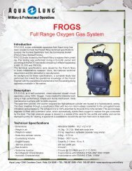
10 Odyssea Technical ManualPocketThe Odyssea features one large utility pocket located on the left lobe of the BCand two retainers on the right side designed to carry an emergency strobe lightand a snorkel.Drain PlugThe Odyssea is equipped with two drain caps located on the back of each lobeof the BC. The caps are used to rinse the inside of the bladder.AUXILIARY AIR CYLINDERThe auxiliary cylinder is attached to the Odyssea by means of a threadedhand fitting (Fig. 2). Air is added to the Odyssea by opening the cylinder valve.Required for closed circuit and semi-closed circuit diving.P/N 840970P/N 101338Fig. 2Filling the Auxiliary CylinderTo fill the cylinder, you will need an optional fill adapter w/ GERS connection <strong>Aqua</strong><strong>Lung</strong> part number 840817.1. Before attempting to fill the auxiliary cylinder, ensure that the fill adapter andvalve are completely dry - especially in the area surrounding the valve outletExamine the cylinder markings to verify that it is rated for a fill pressure of 200BAR (2,900 PSI).2. Using a calibrated pressure gauge, check the supply cylinder is filledto 200 BAR (2,900 PSI). It is very important to ensure that the auxiliarycylinder is filled to its total capacity, but not overfilled.WARNING: DO NOT attempt to fill the cylinder if the markings indicate that it is ratedfor a different fill pressure other than 200 BAR (2,900 PSI) Doing so may result in ruptureor explosion in the event of fire or overfilling. Instead, immediately return the unitto a qualified technician and do not use under any circumstances.
113. Inspect the o-ring at the end of the fill adapter to make sure it is in goodcondition. Thread the adapter onto the threaded outlet boss on the cylinder valveuntil finger tight (Fig. 3).CheckO-ringFig. 34. Loosen the yoke knob. While supporting the auxiliary cylinder in one hand, attachthe adapter to a fully pressurized 200 BAR (2,900 PSI) scuba cylinder (Fig. 4).Relief Plug Yoke KnobFig. 45. Relief plug is fixed in the closed position on the GERS fill adapter when fillingthe auxiliary cylinder from a scuba cylinder.WARNING: DO NOT attempt to fill the auxiliary cylinder from a supply cylinder which containsmore than 200 BAR (2,900 PSI). Doing so may weaken and damage the cylinder.6. Open the handwheel on the auxiliary cylinder counterclockwise until thevalve is completely open.7. VERY SLOWLY open the valve on the scuba cylinder.NOTE: Always fill the auxiliary cylinder as slowly as possible by turning the handwheel of thesupply valve slowly to control the rate of fill. Rapid filling will generate heat and will result inan incomplete fill after the cylinder cools. If the cylinder is warm to the touch afterward, thefill rate was too rapid.
12 Odyssea Technical Manual8. Close the valve of the supply cylinder and then the valve of the auxiliarycylinder. Slowly purge the relief plug by depressing it down with your finger torelieve the high pressure air trapped in the adapter.9. Loosen the yoke knob and remove the adapter from the supply cylinder.Unscrew the adapter from the auxiliary cylinder valve. Place the dust capback in place and tighten the yoke knob.Attaching the Auxiliary Cylinder1. Before attaching the cylinder, inspect the o-ring located at the tip of theconnector (Fig. 5).CheckO-ringFig. 52. Insert the cylinder into the retaining sleeve and align the threaded valve outletwith the cylinder connector. Turn the knurled knob counterclockwise and threadthe cylinder connector onto the valve outlet until finger tight (Fig. 6).Fig. 6
13INFLATION METHODSUsing the Oral InflatorTo orally inflate your BC (Fig. 7), place your lips on the oral inflator mouthpiece(A) and exhale a small amount of air into the mouthpiece to purge any waterthat may still be in the housing. While continuing to exhale into the mouthpiece,depress the oral inflator button (B) to inflate the BC immediately after exhaling,release the oral inflator button to prevent air from escaping.abFig. 7Using the Auxiliary Air CylinderTo inflate the BC using the auxiliary air cylinder, open the cylinder valve by turning thehandwheel counterclockwise. Close the cylinder valve when the bladder is adequatelyfilled, otherwise, air will escape from the over pressure relief valves.DEFLATION METHODSThroughout the course of a dive, it will be necessary to release air from theOdyssea using one of the three methods described in the followinginstructions. Each method uses a valve that is in a different location. The methodyou choose at any time may depend on whether you are making your initial descentfeet-first, head-first, or maintaining neutral buoyancy underwater. Alwaysremember to utilize the valve that is at the highest point on the bladder (closestto the surface), depending on your position in the water.Deflation via Oral InflatorTo deflate the Odyssea using the oral inflator, lift the inflator body to its highestpossible position (above the head). Press the oral inflator button (See Fig.7B) tostart venting air. This method is most effective on the surface when starting theinitial descent.NOTE: Depressing the oral inflator while the jacket is empty may cause water to enter theair bladder.
14 Odyssea Technical ManualDeflation via Dual Exhaust ValveInside the inflator’s corrugated hose is a nylon line that attaches the inflator to thedual valve at the top of the airway assembly. You can vent air from the Odysseaby firmly pulling straight down on the inflator. Once resistance is felt, only a pullof 7mm (.25 in) is required. The Rapid Exhaust Valve (REV) provides an effectiveand convenient way to vent air from the BC while in either an upright or facedown swimming position (Fig. 8). It also functions as an over pressure relief valve(OPRV) valve that will open automatically to relieve air pressure. This feature isvery critical for preventing stress or damage to the BC’s bladder (Fig. 9).Fig. 8Deflation via Over Pressure Relief Valve (OPRV)In addition to the over pressure relief valve(OPRV) that is integrated into the dual valve,the Odyssea has another OPRV/dump valve(Fig. 10) located on the lower right lobe (A),opposite the auxiliary air cylinder attachment.The OPRV primary function is to relieveexcess air pressure inside the bladder, butit can also be opened manually by pullingon the ball and cord assembly (B) to quicklydump air.Fig. 9AFig. 10BCAUTION: The proper function of the over pressure relief valve is vital to preventdamage to the BC bladder. Unauthorized service or tampering may render thesevalves inoperable, and could cause the bladder to leak or burst. This type of damageis not repairable and is not covered under warranty.WARNING: Most training agencies recommend that you descend in an upright, feetfirstposition, in order to maintain a slower and more controlled descent. This is especiallytrue if you experience difficulty equalizing your ears or if you are descendingin low visibility conditions.
15DONNING & ADJUSTMENT PROCEDURESDonning1. One end of the crotch strap ( Fig.11) has asingle male quick-release buckle. The other endhas two male quick-release buckles. Connectthe single male connection to the female bucklelocated at the top of the Odyssea (A). Secure theexcess webbing through the 3-bar slide (E)2. Connect the rear lobe retaining strap toone of the connection points on the lower lobe(B). Insert the free end of the lobe retaining strapthrough the sewn-in loop on the crotch strap (C).3. Insert your arm through the straps as if youwere putting on a jacket. Reach back and hold theunconnected female buckle with one hand andinsert the male buckle with the other hand (D).ABCEDFig. 114. Bring the free end of the crotch strap(Fig.12) between your legs and connect it tothe two lower female buckles at the front of theOdyssea (Fig. 12A).B5. Connect the chest strap to the two upper femalebuckles at the front of the Odyssea just abovewhere the crotch strap is attached (Fig. 12B).AAdjusting strap length1. The length of the straps may be adjustedby holding the strap and moving the 3-bar slide(Fig. 11E) up or down the strap. After adjustingthe position of the 3-bar slide, readjust the strapthrough the quick release buckle.2. Once the straps are readjusted, don theOdyssea to make sure the adjustments arecorrect.Fig. 12
16 Odyssea Technical ManualPRE-DIVE INSPECTIONWARNING: Before each use, the Odyssea must be given a thorough visual inspectionand functional test. NEVER dive with an Odyssea that shows signs of damageto its bladder or valves until it has received a complete inspection and service froman authorized repair technician.Inspection Checklist1. Orally inflate the Odyssea until the bladder is completely full. Manuallyoperate the OPRV/dump valve by pulling on the attached ball and cord to releaseair from the Odyssea (Fig. 13). Release the ball and cord, verify the OPRV/dumpvalve re-seats. Re-inflate the jacket and pull down on the oral inflator assemblyto check the function of the REV, only a pull of 7mm (.25 in) is required onceresistance is felt (Fig. 14) Use cylinder air if required to activate OPRV.Pull DownOn OralInflatorFig. 13 Fig. 142. Fully inflate the Odyssea once again and let it sit for 10 minutes to check forleans and firmness (Fig. 15).WARNING: If you can hear any leaks, or if the bladder begins to deflate within 10 minutes,DO NOT attempt to use the Odyssea until it has received service.Fig. 15
173. Inspect all quick release buckles (both male and female ends) that are attachedat the top, sides and on the crotch strap of the Odyssea for cracks, breakage orgeneral damage. Please refer to the diagram in the donning and adjustmentprocedures section for specific quick release buckle locations (Figs. 16-18).Fig.16 Fig. 17Fig. 184. Check stitching points on the cylinder retaining sleeve, quick release buckles,webbing, crotch & lobe retaining straps. Verify there is no excess wear to any ofthe sections of webbing on the Odyssey (Figs. 19-21).Fig. 19 Fig. 20Check stitching pointsFig. 21
18 Odyssea Technical Manual5. Ensure the outer bag zipper is not damaged, none of the zipper teeth aremissing and the zipper moves freely and is closed (Figs. 22 & 23).Fig. 22 Fig. 236. Verify all hook and loop material is not excessively worn and it is in goodworking condition (Figs. 24-26).Fig. 24 Fig. 25Fig. 26
197. Check the dual valve connector, caps, dump valve connector and cylinderconnector making sure they are sealed and no air is escaping (Figs. 27-30).Fig. 27 Fig. 28Fig. 29Fig. 308. Ensure that the auxiliary air cylinder has been completely filled to200 BAR (2,900 PSI) (Fig. 31).Fig. 31
20 Odyssea Technical ManualPOST DIVE CARE & MAINTENANCEWith proper care, the Odyssea will provide many years of reliable service. The followingpreventive maintenance must be performed to extend the life of the Odyssea:1. Avoid prolonged exposure to direct sunlight and extreme heat. Nylonfabric can quickly fade when exposed to the sun’s ultraviolet rays andextreme heat may damage the welded bladder seams.2. Avoid repeated or prolonged use in heavily chlorinated water, which cancause the Odyssea fabric to discolor and decay prematurely.3. Do not allow the Odyssea to chafe against any sharp objects or roughsurfaces that could abrade or puncture the bladder. Do not set or drop heavyobjects such as cylinders or block weights on the Odyssea.4.Avoid any contact with oil, gasoline, aerosols, or chemical solvents.5. After diving, give the Odyssea a thorough fresh water rinse. Unzip theouter shell and check for water inside the urethane air bladder. If there isany water inside the bladder, it must be rinsed out with fresh water usingthe following procedure:a) Unscrew one of the drain caps (Fig. 32).Fig. 32b) Using a fresh water supply, fill the bladder until about a 1/4 full and reinstall the drain cap. Thoroughly shake the bladder so the water rinses theentire inside of the bladder. Unscrew both drain caps, cylinder connector,OPRV and oral airway assembly and let all the water drain from the bladder.Leave the drain caps, cylinder connector, OPRV and oral airway assembly offuntil the inside of the bladder is dry (Figs. 33 & 34).Fig. 33 Fig. 34
c) Reinstall the drain caps, OPRV, cylinder connector and oral airway assembly.Orally inflate the Odyssea until it is partially inflated. Store the Odyssea partiallyinflated, away from direct sunlight, in a clean, dry area. Do not store in an enclosedspace, such as a car trunk, where temperatures may fall below -18ºC (0ºF) or riseabove 49ºC (120ºF).21
22 Odyssea Technical ManualBC Bladder Removal1. Unscrew the knurled nut on the GERS cylinder connectorand remove the cylinder from the BC. After the cylinder has beenremoved, loosen the cylinder connector (60) and remove the cylinderconnector from the bladder connection.2. Remove all straps with quick release buckles (61 & 62), bothcaps (63), gaskets (12), dump valve (64), and airway (59).3. Unzip external zipper, push bladder connectors into the outer bag(58). Carefully remove the bladder (57), making sure the connectorsdo not get caught on the outer bag.
23BC Bladder Installation1. Insert the bladder (57) back into the outer bag (58) so that theconnectors line up with the connector holes.4. Turn the cylinder valve on to inflate the bladder until the overpressure relief valve (OPRV) releases the excess air from thebladder. Turn off cylinder and remove the cylinder from the BC.Check both caps (63), dump valve (64), airway (59) and cylinderconnector (60) for any signs of leakage. If no leakage is detected,let bladder stand inflated for one hour. Check the firmness of thebladder after one hour has passed. If the bladder has remainedfirm, no air loss has occurred. If the bladder has lost air, recheckall connections, inflate BC, submerge and check for leaks.2. Inspect gasket(s) (12) for damage, this component may bereused if no damage is noticed. Place gasket(s) back into the connectors.Install caps (63), dump valve (64), and airway (59) backonto the corresponding connectors. Put strap assemblies (61 &62) back into place.3. Ensure the gasket (12) has been placed back into the connectorin which the cylinder connector will be attached. Attach theGERS cylinder connector (60) and turn clockwise until hand tight.Insert the auxiliary cylinder into the retaining sleeve and tighten theknurled nut onto the cylinder valve adapter.
24 Odyssea Technical ManualNote: Before performing any disassembly, refer to theexploded parts drawing which references all mandatoryreplacement parts. These parts should be replaced withnew and must not be reused under any circumstancesregardless of the age of the valve or how much use ithas received since it was last serviced.3. Pull back the hose (24) from the mouthpiece body (29). Pressthe pin (28) out from one side using a pin punch or similar tool torelease the braided nylon cord (23). Remove the hose (24) from thedual valve assembly, set the dual valve assembly to the side.CAUTION: Use only a plastic (pn 103102) or brasso-ring removal tool (pn 944022) when removing o-rings to prevent damage to the sealing surface.Even a small scratch across an o-ring sealing surfacecould result in leakage. Once an o-ring sealingsurface has been damaged, the part must bereplaced with new. DO NOT use a dental pick orany other steel instrument.Airway Non-Mag MaintenanceProceduresORAL INFLATORDisassembly1. Using the spanner wrench (pn 129198) to hold the push button(37), remove the locknut (25) from the stem (33) with a 5.5mm nutdriver. Use needle nose pliers to remove the washer (26) and therubber valve (27). Discard nut (25) and rubber valve (27).Airway (Non Mag) Disassembly1. Turn the retaining collar and remove the dual valve assemblyfrom the connector. Remove the gasket (12) from the connector.2. Using a straight blade screwdriver, carefully lift out the fingers ofthe cage (38) and remove it from lower inflator housing (29).2. Using diagonal pliers (pn 9-45171), carefully remove the threeclamps (22) from the spiral hose (24) securing the inflator and dualvalve assemblies.CAUTION: Do not apply excessive force or pry againstthe housing/cage with the tip of the screwdriver.CAUTION: Do not cut the spiral hose while removingthe clamp.
253. Remove the stem assembly and spring (32) through the front ofthe lower inflator housing (31). Remove the mouthpiece (30) fromthe mouthpiece body (29).Airway (Non Mag) DisassemblyDUAL-VALVEDisassembly4. Using the spanner wrench (pn 129198), turn the push button (37)counterclockwise to loosen. It may be necessary to secure the stem(33) in a vise or a pair of soft jawed pliers to loosen the push button(37) as a small amount of Loctite 425 or 480 is used to secure thebutton. Ensure the stem is protected from damage.NOTE: The outer cap is bonded to the body of the dualvalve assembly with a non-permanent adhesive. It will be necessaryto separate this bond prior to performing further disassemblyby carefully following the procedure outlined below.1. Locate the seam that runs along the circumference between thedual valve body (13) and the outer cap (17), where the cap is fastenedto the body. Using the plastic handle of a medium size screwdriver,or similar lightweight blunt instrument, rap sharply against all points ofthe seam on the cap to break the adhesive bond.Seam5. Remove the push button (37), washer (36) and the inflatordiaphragm (35) from the stem (33). Next, remove the plastic valve(34) from the stem (33). It may be necessary to secure the stem ina vise or a pair of soft jawed pliers to remove the plastic valve asa small amount of Loctite 425 or 480 is used on the threads of thestem (33). Once removed, discard the push button (37), washer(36), inflator diaphragm (35) and plastic valve (34).CAUTION: Do not apply excessive force or use a hammer,mallet or other heavy instrument.2. While holding the dual valve assembly secure, firmly graspthe outer cap (17) and turn it counter-clockwise to loosen. Whilemaintaining slight inward pressure to counteract the spring pressureinside, continue turning the cap (17) until it has disengagedfrom the dual valve body (13). Remove the cap and the spring(16) beneath it. Closely examine the cap to check for any signs ofthread damage, distortion, cracking, or chemical attack that mayindicate the use of excessive force or incorrect adhesive duringprevious service.6. Clean any residual Loctite from the large threads of the stem (33).NOTE: If the cap cannot be turned, repeat step 1 tobreak the adhesive bond.This Concludes Disassembly of the Oral InflatorBefore starting assembly, perform parts cleaningand lubrication in accordance with ProcedureA: Cleaning and Lubricating in the backof the manual.
26 Odyssea Technical Manual3. Remove the valve plate (15) with gasket (12) from the body (13)and remove the gasket from the valve plate. Discard the gasket andset the valve plate aside.NOTE: Before performing any assembly, it is importantto inspect all parts, both new and those that are beingreused, to ensure that every part and component is perfectlyclean and free of any dust, corrosion or blemishes.Before dressing each o-ring with Christo-Lube ® , check toensure it is clean, supple and free of any blemish.4. Locate the two holes on opposite sides of the barrel of the dualvalve body (13) which hold the arms of the poppet guide (21). Toremove the poppet guide and exhaust valve assembly from thedual valve body, press the arms of the poppet guide inward bysimultaneously inserting two small probes through the opposingholes in the barrel.WARNING: Use only genuine <strong>Aqua</strong> <strong>Lung</strong> ® parts, subassembliesand components whenever assemblingany <strong>Aqua</strong> <strong>Lung</strong> ® product. DO NOT attempt to substitutean <strong>Aqua</strong> <strong>Lung</strong> ® part with another manufacturer’s,regardless of any similarity in shape, size or appearance.Doing so may render the product unsafeand could result in serious injury or death.Airway (Non Mag) AssemblyORAL INFLATORAssembly5. When the arms of the poppet guide have disengaged from thebody, firmly grasp the braided nylon cord (23) and pull the exhaustvalve assembly straight out while holding the body secure. This willpull the poppet stem (19) out of the dump valve poppet (18). Removethe dump valve poppet and discard.1. Place the large end of the spring (32) into the lower inflatorhousing (31). Ensure the spring is oriented properly.6. Remove the braided nylon cord (23) from the poppet stem (19).Pull the poppet stem (19) and spring (20) straight out of the poppetguide (21).2. Place one drop of Loctite 425 or 480 onto the base of the largediameter threads of the stem (33). Screw the plastic valve (34)onto the large diameter threads of the stem (33) until seated handtight. The taper of the plastic valve must face towards the centerof the stem.Loctite425 or 480This Concludes Disassembly of the Dual ValveBefore starting assembly, perform parts cleaningand lubrication in accordance with ProcedureA: Cleaning and Lubricating in the backof the manual.
273. Install the diaphragm (35) over the large threaded end of thestem (33) until it rests against the face of the plastic valve (34).Place the washer (36) on top of the diaphragm (35) followed by onedrop of Loctite 425 or 480 onto the tip of the stem (large threads)and screw the button (37) onto the stem (33) until it bottoms outagainst the washer (36).6. Using needle nose pliers, place the rubber valve (27) flat end upover the small diameter threads of the stem (33). Install the washer(26) onto the small diameter thread end of the stem (33) so thatthe washer (26) is seated on top of the rubber valve (27). Place thelocknut (25) into a 5.5mm nut driver and engage the locknut ontothe stem assembly by turning clockwise.Loctite425 or 4804. Pass the stem assembly into the body, through the center of thespring (32). Ensure the stem assembly is centred properly.5. Set the cage (38) with the fingers facing out over the push button(37) of the assembly. Place the entire lower inflator assembly facedown on a clean surface against the cage (38). Secure the cageto the lower inflator assembly by using an arbor press or gentlystriking with a rubber mallet. Check the assembly to ensure all ofthe fingers of the cage are engaged in the internal groove of thelower inflator housing assembly.7. Insert the pin spanner (pn 129198) into the holes on the button.(37). Using the 5.5mm nut driver, turn the locknut (25) clockwiseuntil approximately 1/4 inch of the threads of the stem (33) areexposed opposite the locknut.8. Install mouthpiece (30) onto the mouthpiece body (29) with thecurved end facing out until the lower inflator housing seats into themouthpiece groove.CAUTION: Do not use excessive force while installingthe cage. Doing so could cause damage to the case orlower housing.This Concludes Assembly of the Oral Inflator.Please Refer to Final Assembly and Testing inthe back of the manual.
28 Odyssea Technical ManualAirway (Non Mag) AssemblyDUAL-VALVEAssembly1. Dip the dump valve poppet (18) into soapy water and press securelyonto the barbed tip of the poppet stem (19). Slide the spring(20) onto the stem.3. Compress the poppet assembly with the forked end out ontothe poppet holding fixture. Using the inflator cord fixture, install thebraided nylon cord (23) through the hole in the poppet stem (19)and round the inflator cord post 2 times (Two loops around postand two passes through the stem). Tie a 2.5 cm (1 inch) loop onone end of the cord using a “Overhand Bow Knot”. Secure the cordby going through the open loop with the opposite cord end andtying three (3) “Half Hitches”. Trim the excess cord to 1/4 inch atboth knots and seal the cord ends using a propane lighter (fixturescan be locally manufactured).CAUTION: Do not damage the knots with the flame.2. Insert the poppet stem (19) through the flat end of the poppetguide (21).Distance between posts30.5 cm (12 inches)Overhand Bow Knot(3) Half Hitches4. Position the poppet guide assembly so that the larger rib facestoward the open side of the dual valve body (13), away from themanifold. Lubricate the dump valve poppet with a small amountof soapy water, and align the arms of the poppet guide with thegrooves inside the barrel of the body. Insert the assembly into thebarrel only until the ears of the poppet guide rest above the rim.Large Rib
30 Odyssea Technical Manual4. Insert retaining pin (28) half way into one hole of the bodymouthpiece (29). Capture both loop ends of the braided nylon cord(23) using your thumb and index finger facing up, slide the hose(24) back for clearance. Rotate your wrist pointing your thumb andindex finger down to form a “Larks Head Knot” on both loop ends.Capture the knot onto the pin (28) of the body mouthpiece.Note: Before performing any disassembly, refer to theexploded parts drawing, which references all mandatoryreplacement parts. These parts should be replaced withnew, and must not be reused under any circumstancesregardless of the age of the valve or how much use it hasreceived since it was last serviced.CAUTION: Use only a plastic (pn 103102) or brass o-ring removal tool (pn 944022) when removing o-ringsto prevent damage to the sealing surface. Even a smallscratch across an o-ring sealing surface could resultin leakage. Once an o-ring sealing surface has beendamaged, the part must be replaced with new. DO NOTuse a dental pick or any other steel instrument.Cylinder Connector (GERS)Maintenance ProceduresDisassembly5. Press the pin (28) by hand until it engages equally into bothholes of the body mouthpiece (29). Apply a small amount of Gasgacinchto the diameter of the body mouthpiece hose barb. Allow15 seconds for the adhesive to get tacky and slide the hose ontothe body mouthpiece, with the mouthpiece facing to the right handside of the user as worn.1. Remove the GERS connector (60) from the BC connector byunscrewing counterclockwise.2. Remove the gasket (12) and closely inspect it for damage, if damagedreplace the gasket. Examine the BC connector for any damage.If any debris is found in the groove, use a clean cloth to remove.6. Secure each of the two clamps (22) to the spiral hose (24). Theoutside clamp head faces in line with the mouthpiece. Clamp edgedistance to the end of the hose is 3.18mm (1/8 inch). The otherclamp faces the opposite direction over the pin (28).Clamp 23. Looking at the bottom side of the cylinder connector locate theretaining ring (11). Using circlip pliers (pn 111100), remove the snapring (11) from the connector (6). Remove the connector assemblyfrom the handwheel (10).Clamp 1This Concludes Assembly of the Airway.Please Refer to Final Assembly and Testing inthe back of the manual.
32 Odyssea Technical Manual3. Place the threaded opening of the knurled nut (3) over the endof the cylinder valve connector (2). Place (1) one drop of Loctite#414 Superbonder on the bottom threads of cylinder valve connector(2). Screw the cylinder valve connector (2) into the connector(6). Hold the collar of the connector (6) with soft jaw pliers, usingthe 5mm hex key adapter (pn 8367A23), tighten the cylinder valveconnector (2) into the connector (6) hand tight, then an additional1/4 turn.CYLINDER VALVE MAINTENANCEPROCEDURESNote: Before performing any disassembly, refer to theexploded parts drawing, which references all mandatoryreplacement parts. These parts should be replaced withnew, and must not be reused under any circumstancesregardless of the age of the valve or how much use it hasreceived since it was last serviced.(1) Drop of Loctite#414 SuperbonderNote: Excessive Loctite 414 Superbonder may cause theknurled nut to stick to the valve reducing connector. Rotatethe knurled nut to free.CAUTION: Do not cross thread or overtighten thevalve reducing connector into the connector, thiscan cause irreversible damage to components.CAUTION: Protective eyeware must be worn during installationof cylinder valve connector into the connector.4. Install o-ring (7) into the groove on the connector (6), then installconnector into handwheel (10) from the outside.CAUTION: Use only a plastic (pn 103102) or brass o-ring removal tool (pn 944022) when removing o-ringsto prevent damage to the sealing surface. Even a smallscratch across an o-ring sealing surface could resultin leakage. Once an o-ring sealing surface has beendamaged, the part must be replaced with new. DONOT use a dental pick or any other steel instrument.Valve Disassembly1. Open cylinder valve counterclockwise and ensure cylinder (56)is fully depressurized. Secure cylinder in cylinder vise (pn 100397)and remove the cylinder valve from the cylinder by turning valvebody (54) counterclockwise with a 27mm (1-1/16 inch) crowfoot(pn FC34A) and 3/8” flex handle drive (pn 9-44363). When done,remove cylinder from cylinder vise.5. Turn the GERS connector assembly over so that the bottom ofthe assembly is face up. Use circlip pliers (pn 111100) to install theretaining ring (11). Verify that the flat side of the retaining ring is upand the retaining ring is completely closed securing the connectorassembly into the handwheel (10).2. Remove the o-ring (55) from the valve body (54). Use the appropriateo-ring tool (pn 944022). Discard o-ring.This Concludes Assembly of the GERS CylinderConnector.Please Refer to Final Assembly and Testing inthe back of the manual.
333. Use the modified screwdriver (pn 941586), remove the handwheelnut (41), spring (42), handwheel (43) and washer (44) fromthe spindle (49).6. Holding the valve body assembly in a vise, use a 22mm (7/8inch) socket (pn 769354) and 3/8” flex handle drive (pn 9-44363) toremove the valve plug (45) from the body (54).7. Remove the o-ring (46) from the valve plug (45) using the appropriateo-ring tool (pn 944022). Discard o-ring.4. Unscrew the valve seat adapter (52) from the body (54) usinga 3/8” flex handle drive (pn 9-44363) and 5mm hex key adapter(pn 8367A23).CAUTION: Loctite 242 is used to hold this part in placein addition to the torque applied during assembly.8. Unscrew the valve seat (51) from the body (54) using the spindle(49) and oldham (50). Remove the oldham (50) and valve seat(51), discard the valve seat.Note: If the valve seat adapter does not loosen, use a heatgun to heat up the body and adapter to loosen the adhesive.CAUTION: Do not damage the internal surface ofthe valve seat adapter.9. Using your fingers, remove the washer (47) from the spindle(49). Take the brass o-ring tool (pn 944022) and remove the o-ring(48) from the groove in the spindle (49). Discard the o-ring.5. Remove the o-ring (53) from the valve seat adapter (52) anddiscard it.Note: If the washer (47) does not come out on the spindle(49), check for it inside the valve plug (45).This Concludes Disassembly of the Cylinder Valve.Before starting assembly, perform parts cleaningand lubrication in accordance with ProcedureA: Cleaning and Lubricating in the backof the manual.
34 Odyssea Technical ManualCYLINDER VALVE MAINTENANCEPROCEDURESNOTE: Before performing any reassembly, it is importantto inspect all parts, both new and those that are beingreused, to ensure that every part and component is perfectlyclean and free of any dust, corrosion, or blemishes.Before dressing each o-ring with Christo-Lube ® , check toensure it is clean, supple, and free of any blemish.3. Lubricate the o-ring (46) and install it on to the valve plug (45).Screw the valve plug (45) back in to the body (54) until hand tight.Using a Newton Meter torque wrench and a 22mm (7/8 inch) socket,(pn 769354) tighten the valve plug to 15 Nm (133 in.lbs). Ensurethe o-ring (46) is seated inside the body (54).WARNING: Use only genuine <strong>Aqua</strong> <strong>Lung</strong> ® parts,sub-assemblies, and components whenever assemblingany <strong>Aqua</strong> <strong>Lung</strong> ® product. DO NOT attempt tosubstitute an <strong>Aqua</strong> <strong>Lung</strong> ® part with another manufacturer’s,regardless of any similarity in shape, size orappearance. Doing so may render the product unsafe,and could result in serious injury or death.4. Install the washer (44) over the tip of the spindle (49) followedby the handwheel (43).Valve Assembly1. Lubricate the o-ring (48) and install it into the groove of thespindle (49). Next, install a lubricated washer (47) back on to thespindle (49).2. Lubricate the threads and screw the valve seat (51) into the body(54) using the oldham (50) and spindle (49). Insert the handwheel(43) over the tip of the spindle, this will ensure that the valve seat(51) is properly seated. After the valve seat has been tightened,remove the handwheel, leaving the spindle and oldham in place.5. Place the spring (42) over the tip of the spindle (49) so that it isresting on top of the handwheel (43). Install the handwheel nut (41)onto the spindle (49), start threading it by hand, then tighten therest of the way with a modified screwdriver (pn 941586). It shouldbe tightened down until the spindle (49) is even with the top of thehandwheel nut (41).CAUTION: If any resistance is felt while threadinghandwheel nut onto spindle, stop and start over. Ensurethat cross threading is not occurring.
356. Apply a small amount of lubrication to the o-ring (53) and fit ontothe valve seat adapter (52). Apply one drop of Loctite 242 to thesmall threads and screw the valve seat adapter (52) into the body(54) hand tight. Using a Newton Meter torque wrench along witha 5mm hex key adapter (pn 8367A23), apply 10 Nm (89 in.lbs) oftorque to the valve seat adapter (52).Loctite 242 hereCAUTION: Do not lubricate threads of the valve seatadapter.7. Lubricate o-ring (55) and place it onto the body over the threadsand up on the shoulder. Lightly lubricate the threads of the body(54). Install cylinder (56) into cylinder vise (pn 100397) and screwthe body into the cylinder until hand tight. Using a 27mm (1-1/16inch) crowfoot (pn FC34A) and Newton Meter torque wrench, tightenvalve assembly into cylinder to 30 Nm (22 ft.lbs).This Concludes Assembly of the Cylinder ValveCylinder Valve Testing Procedures1. Fill cylinder to 34 BAR (500 PSI) and listen for audible leaks.Submerge in a fresh water supply and visually inspect valve for anyleaks that may be preset. If no leaks are detected, fill cylinder to200 BAR (2,900 PSI), again listen for audible leaks and submergein fresh water. If any leaks are detected, disassemble valve, replaceworn parts, rebuild and retest.
36 Odyssea Technical ManualFINAL ASSEMBLY AND TESTINGWARNING: Protective eyewear must be worn at alltimes during testing.1. Lay the gasket (12) flat inside the connector and mate the retainingcollar of the dual valve body (13) directly over it, onto the manifold.Gently turn the collar clockwise to engage the threads, being carefulto avoid cross threading, and hold the airway in the desired positionwhile tightening the retaining collar by hand until snug.3. While holding the dual valve assembly secure, firmly grasp theinflator assembly and pull it in a straight line directly away from thedual valve assembly. Check the attachment points of the airwaytube at both the dual valve assembly and the inflator assembly. Ifany signs of damage or decay can be detected, it is important toreplace the airway tube before proceeding any further.NOTE: Ensure the dual valve body (13) sealing surfaceis properly aligned with the connector on the BC This isessential to achieve a proper seal.NOTE: Ensure that cylinder connectors, oral airway assembly,caps and OPRV are secured to the BC prior tosubmerging. Failure to do so will cause water to enter theinternal bladder.2. Lay the gasket (12) flat inside the connector and mate the retainingcollar of the cylinder connector (60) directly over it onto themanifold. Gently turn the collar clockwise to engage the threads,being careful to avoid cross threading and hold the GERS cylinderconnector in the desired position while tightening the retaining collarby hand until snug.4. Immerse the inflator and surrounding area of the spiral tube infresh water to wet the lower portion of the airway assembly. Graspthe spiral tube approximately six inches above the inflator assemblyand pull the tube in a straight line away from the inflator withmoderate force while holding the inflator secure. Check to ensurethat no separation occurs at the attachment point, and the tuberemains seated flush against the base of the inflator housing.CAUTION: Do not use tool to tighten the retaining collaronto the BC connector. Doing so may result in overtightening and /or cross threading and could causepermanent damage that will require replacement ofthe BC bladder.5. Finally, bend the airway tube at a right angle. If the airway tubeshows any sign of separating from the inflator assembly it is importantto replace the clamp.
376. Manually inflate the BC until it is taut and fully inflated. Pressthe deflation button (37) and then pull down on the oral inflator toensure a rapid and unobstructed exhaust using both methods ofdeflation. Fully inflate the BC once again, and listen closely for anysigns of leakage.Push to DeflatePull Down OnOral Inflator ToDeflate7. Connect the cylinder to the cylinder connector, turn the cylindervalve on to inflate the bladder until the over pressure relief valve(OPRV) releases the excess air from the bladder. Turn off cylinderand remove the cylinder from the BC. Check caps (63), airway (59),OPRV (64) and cylinder connector (60) for any signs of leakage.If no leakage is detected, let bladder stand inflated for one hour.Check the firmness of the bladder after one hour has passed. If thebladder has remained firm, no air loss has occurred. If the bladderhas lost air, recheck all connections, inflate BC, submerge andcheck for leaks. If a continuous leak is detected, the componentmust be disassembled and examined for damage or contaminationof the seals and seating surfaces.NOTE: If leakage is not immediately detected, allow the BCto stand for at least one hour to ensure that none exists.This Concludes The Testing Procedures ForThe Airway (Non-Mag)CAUTION: If the Odyssea is being used for Non-Magapplications, it must be tested on with a MagnetometerIAW with STANAG requirements 2897 EOD.
38 Odyssea Technical ManualBC Patch Kit InstructionsWARNING: Do not attempt to perform these proceduresusing patches or adhesive other than thoseprovided in the BC Patch Kit pn 42611.3. Apply a generous coat of Weld-On 4784® adhesive to the materialof the BC surrounding the hole or tear. Allow this preliminarycoat to set for at least twenty four hours.WARNING: Do not attempt to patch a tear or puncturewhich is located directly over an internal baffle, within50mm (2 inches) of a seam or is larger than 13mm (1/2inch) in diameter or length.WARNING: Adhesive should only be applied in aroom with plenty of cross ventilation. Carefully readall cautions on the label of the adhesive and avoidinhaling vapors.BC Patch KitCAUTION: It is important to prevent any adhesion betweenthe internal surfaces of the bladder caused bythe entrance of adhesive through the hole or tear. Positionthe bladder as needed to maintain a separation ofthe bladder at the point of the hole or tear.4. After twenty four hours have elapsed, apply a generous secondcoat of adhesive to the material of the BC surrounding the holeor tear, and to the glossy surface only of the patch. Wait exactlytwenty minutes.Glossy SideNon-Glossy Side1. Inspect the material of the BC surrounding the hole or tear toensure that it is perfectly clean and dry. Rinse and dry the BC toclean if necessary.5. After twenty minutes have elapsed, apply a third coat of adhesiveto the BC material, a second coat to the patch. Wait betweenfive to ten minutes for this coat to grow tacky, and immediately applythe patch over the hole or tear, using a small roller to press outany pockets of air that may be present between the patch and BCmaterial. Position a 2.27 kg (5 Lb.) weight directly over the patch toapply pressure, and allow exactly one hour for the patch to set.2. Check to ensure that the patch extends at least twice the diameteror length of the hole or tear on all sides.NOTE: DO NOT allow the patch to set more than onehour before performing the next step.6. Partially inflate the BC no more than 1/2 full, causing the innersurface of the bladder to separate if adhesion has occurred. Applya final coat of adhesive over the entire patch area. Allow twentyfour hours to completely cure, an then fully inflate the BC to ensurethat leakage is no longer present. If the BC does not remaincompletely full for at least one hour, immerse it in fresh water todetermine the source of leakage and repair as needed.This Concludes BC Patch Kit Instructions
39Table 1: LIST OF TOOLSPART # DESCRIPTION APPLICATION129198 Adjustable FaceSpannerRemoval/Installation of Oral Inflator Push Button (39)101215 Tank FillAdapterCharging cylinder944022103102820466(2 oz.)O-ring Tool Kit(Brass)O-Ring Tool(Plastic, 5 pk)Christo-LubeMCG 111Removal/Installation of o-ringsLubrication of O-rings/Parts820467(16 oz.)9-44363 Flex HandleDrive 3/8”Removal/Installation of Valve/Connector Parts111100 Circlip Pliers Removal/Installation of Circlip (11) on GERS connector100398 Vise Jaw Inserts for Cylinder( For Existing Shop Vise)Removal/Installation of Cylinder Valve100397 Table MountCylinder ViseSecures Cylinder (56) for Removal/Installation of CylinderValve9-45171 Diagonal Pliers(small)Removal/Installation of Clamp (22 & 26)941586 ModifiedScrewdriver(short)Removal/Installation of Handwheel Nut (41)8367A235mm Hex Key AdapterRemoval/Installation of Adapter Valve Seat (52) and CylinderValve Connector (2)769354 22mm (7/8 inch)SocketRemoval/Installation of Plug Valve (45)
40 Odyssea Technical ManualTable 1: LIST OF TOOLS (continued)PART # DESCRIPTION APPLICATIONFC34A 27mm (1-1/16 inch) Crowfoot Removal/Installation of Valve Body (54)N/ACord Hook(Locally Manufactured)Installing Braided Nylon Cord (23) through Spiral Hose (24)N/APoppet Fixture(Locally Manufactured)Removal/Installation of Braided Nylon Cord (23)N/ACord Fixture(Locally Manufactured)Knot Tying Fixture for Braided Nylon Cord (23)N/A5.5mm Nut Driver5mm Nut DriverRemoval/Installation of Oral Inflator Locknut (27)Removal/Installation of GERS Cylinder Connector SealingPin Nut (4)N/A Small Punch Removal/Installation of Poppet Guide (21) and Oral InflatorPin (30)N/A Pliers Removal/Installation of Oral Inflator Stem (35)N/AN/A3/8 Drive TorqueWrench; 0-15 Nm(0-132 in.lbs)Range3/8 Drive TorqueWrench; 0-110 Nm(0-81 ft.lbs)RangeTorquing of PartsTorquing of PartsN/A Screw Driver Removal/ Installation of Dual Valve Cap (17), ConnectorSealing Pin (9)N/A Soft Jawed Pliers Removal/Installation to Secure GERS Connector (6)N/ANeedle NosePliersRemoval/Installation of Inflator parts
41Table 2: Torque SpecificationsPART # DESCRIPTION / KEY ITEM # TORQUE840923 Plug, valve (45) 15 Nm (133 in.lbs)840917 Body, valve (54) 30 Nm (22 ft.lbs)840919 Adapter, valve seat (52) 10 Nm (89 in.lbs)Table 3: Recommended Cleaners and LubricantsLUBRICANT/CLEANER APPLICATION SOURCEChristo-Lube MCG 111All o-rings<strong>Aqua</strong> <strong>Lung</strong>, PN 820466, orLubrication Technologies310 Morton StreetJackson, OH 45640(800) 477-8704CAUTION: Silicone rubber requires no lubrication or preservative treatment. DONOT apply grease or spray to silicone rubber parts. Doing so may cause a chemicalbreakdown and premature deterioration of the material.Oakite #31Acid bath for reusable stainless steel andbrass parts.Oakite Products, Inc.50 Valley RoadBerkeley Heights, NJ 07922CAUTION: Do not use muriatic acid for the cleaning of any parts. Even if stronglydiluted, muriatic acid can harm chrome plating and may leave a residue that is harmfulto o-ring seals and other parts.White distilled vinegarNon-ionic Liquid dishwashingdetergent (diluted with warm water)Acid bath for reusable stainless steeland brass parts.Degreaser for brass and stainless steelparts; general cleaning solution for plasticand rubber.“Household” grade“Household” grade
43EXPLODED PARTS DIAGRAMS101338 Connector Cylinder Valve Export StraightKey # PN PN* Description Qty1 820038P 124704 O-ring (20 pk) 12 101090 N/A Connector, valve reducing 13 101029 N/A Nut, Knurled 14 101335 N/A Locknut 5mm 15 101332 840443 Spring 16 101334 850442 Connector 17 820089 N/A O-ring 18 820005 N/A O-ring 19 101328 N/A Pin, sealing 110 101341 862476 Handwheel 111 101344 850443Retaining ring non-mag15.7mm1*<strong>Aqua</strong> <strong>Lung</strong> France Part NumbersGERS45678912Loctite 414 Superbonder3123924231318192021142240Loctite425 or 4801516171022101239 Airway Complete Non MagKey # PN PN* Description Qty12 15309 N/A Gasket, connector seal 413 42742 N/A Dual valve body assembly ACME 114 15714 N/A Gasket, REOP 115 15698 N/A Plate, valve 116 15643 N/A Spring, over pressure, non-mag 117 15707 N/A Cap REOP 118 778559 N/A Poppet, dump valve 119 778556 N/A Stem, poppet, non mag 120 15644 N/A Spring, pull dump, non-mag 121 15649 N/A Guide, poppet 122 15719 N/A Clamp, black, plastic tie 323 17523 N/A Cord braided nylon (1 in) 56 in24 15149 N/A Hose, spiral, 11.5 in 125 101267 116622 Locknut, non mag 126 101247 N/A Washer, non mag 127 101226 840493 Valve, rubber 128 15645 N/A Pin, retaining, non-mag 129 101227 840211 Body, mouthpiece 130 101237 840477 Mouthpiece 131 101231 840482 Housing, lower inflator 132 101246 840490 Spring, non-mag 133 101248 N/A Stem, non-mag 134 101232 840486 Valve, plastic 135 101233 840487 Diaphragm, inflator MP 136 101234 840488 Washer 137 101222 840489 Push button 138 101236 840496 Cage 1Not included in the assembly39 762979 841106 Whistle ball type 140 104913 N/A Clamp strap black 11130282925262733323437353638Loctite 414 Superbonder31Loctite 425 or 480*<strong>Aqua</strong> <strong>Lung</strong> France Part Numbers
44 Odyssea Technical ManualEXPLODED PARTS DIAGRAMS15 Nm4142434445464748495051840970 .43L Cylinder w/Valve (export)Key # PN* Description Qty41 840922 Nut, handwheel 142 228121 Spring 143 228176 Handwheel 144 213421 Washer 145 840923 Plug, valve 146 850218 O-ring 147 840523 Washer 148 840163 O-ring 149 840921 Spindle 150 840199 Oldham 151 228365 Seat, valve 152 840919 Adapter, valve seat 153 850219 O-ring 154 840917 Body 155 850228 O-ring 156 840955 Cylinder .43L 220 BAR, black alu 1*<strong>Aqua</strong> <strong>Lung</strong> France Part Numbers10 NmLoctite 242535430 Nm525556
45ODYSSEA COMPONENTS125965605758Parts Diagram - FrontKey # PN Description Qty12 15309 Gasket, Connector Seal 457 394040 Bladder, Odyssea Export 158 394041 Outer Bag, Odyssea export 159 101239 Airway Complete, Non-Mag 160 101338 Connector, Cylinder Valve Str. Export 161 394093 Crotch Strap 162 394089 Back or Chest Strap 263 15665 Cap ,Universal Connector 264 490620Dump Valve, conv kit ACME 813mm(32 in) universal (non-mag)165 840970 Cylinder, .43Lw/ Valve (Export) 1616263Parts Diagram - Back6364
46 Odyssea Technical ManualOVERHAUL PARTS KITS840556 Kit, Cylinder ConnectorKey # PN PN* Description Qty1 820038 124704 O-ring 14 101335 N/A Locknut 5mm 16 101334 850442 Connector 17 820089 N/A O-ring 18 820005 N/A O-ring 111 101344 850443 Retaining Ring, non-mag 1101240 Kit, Oral Inflator, AtlantisKey # PN PN* Description Qty14 15714 N/A Gasket, REOP 118 778559 N/A Poppet, dump valve 122 15719 N/A Clamp, black 327 101267 116622 Locknut 131 101226 840493 Valve, rubber 131 101232 840486 Valve, plastic 137 101233 840487 Diaphragm, inflator 138 101234 840488 Washer 140 101222 840489 Push button 1840971 Kit, Cylinder (Export)Key # PN* Description Qty46 850218 O-ring 147 840523 Washer 148 840163 O-ring 151 228365 Seat, valve 154 850219 O-ring 155 850228 O-ring 1*<strong>Aqua</strong> <strong>Lung</strong> France Part NumbersKey # PN Description QtyN/A 42611 Bladder Repair Kit 1
47ANNUAL MAINTENANCEThe Odyssea is subject to annual maintenance. All parts listed in the overhaul partskits, must be replaced annually, even if they appear to be in good condition.Composition:• 1 Bladder (Key #57) is constructed of heavy duty urethane with RFwelded seams and connectors.• 1 Outer bag (Key #58) is constructed of 840 Denier nylon.• 1 Rapid exhaust valve (REV) is operated by an easily accessible cord,also acts as an over pressure relief valve (OPRV). (located on inside rightlobe Key #64 and top of airway complete Key #59).• 2 Drain caps (located rear inside lobes Key #63).• 1 Oral inflation system (Key #59).• 1 Auxiliary Air Cylinder, with Valve (GERS connection) (Key #65).(** Refer to Odyssea Components for specific locations)Features:TECHNICAL DATALIFT CAPACITY (Fresh Water) .........20L (46 lbs)CYLINDER CAPACITY ...............1 X .43LCYLINDER WORKING PRESSURE ....200 BAR (2,900 PSI)DUAL VALVE OPENING PRESSURE (non-mag) .09 - .16 BAR (1.3 - 2.3 PSI)OVER PRESSURE RELIEF VALVE OPENING PRESSURE (OPRV) (non-mag) .07 - .14BAR (1 - 2 PSI)DUAL VALVE & OVER PRESSURE RELIEF VALVE (OPRV) CLOSING PRESSURE IS .07BAR (1 PSI) UNDER OPENING PRESSUREWEIGHT (with cylinder) .............2.7 kg (5.9 lbs)(without cylinder) ...........1.7 kg (3.8 lbs)PACKING (Individual box) .............62.2cm X 41cm X 11.4cm24.5” X 16” X 4.5”TOTAL PACKED WEIGHT. ............3.7 kg (8.1 lbs)References:394059: Odyssea ExportAccessories:840970........0.43 L cylinder with valve (GERS connection)15665..........Cap (for use without cylinder)15309..........Connector seal gasket840817........Adapter, tank fill, GERS
48 Odyssea Technical ManualMaintenance Notes
49WARRANTY INFORMATIONAll warranty transactions must be accompanied by proof of original purchase from an <strong>Aqua</strong> <strong>Lung</strong> ® authorizeddealer/agent. Be sure to save your sales receipt, and present it whenever returning your Odysseafor warranty service.The <strong>Aqua</strong> <strong>Lung</strong> ® One Year Limited Warranty <strong>Aqua</strong> <strong>Lung</strong> America warrants to the original purchaser for a period of one year from the date of purchasethat the product will be free from defects in material and workmanship; provided that it receives normaluse, proper care, and prescribed dealer service subject to those restrictions stated below. This limitedwarranty is extended only to the original purchaser for purchases made from an authorized <strong>Aqua</strong> <strong>Lung</strong> ®dealer, and is not transferable. This warranty is limited to repair or replacement only at the discretion of<strong>Aqua</strong> <strong>Lung</strong> America, Inc.ALL WARRANTIES, INCLUDING, BUT NOT LIMITED TO, IMPLIED WARRANTIES, ORMERCHANTABILITY AND FITNESS FOR A PARTICULAR PURPOSE ARE LIMITED INDURATION TO A PERIOD ENDING ONE YEAR FROM THE DATE OF PURCHASE.AQUA LUNG AMERICA DISCLAIMS AND EXCLUDES ANY LIABILITY FOR INCIDENTAL,OR CONSEQUENTIAL DAMAGES. SOME STATES DO NOT ALLOW EXCLUSIONS OFLIABILITY, SO THIS MAY NOT APPLY TO YOU.WARNING: It is dangerous for untrained and uncertified persons to usethe equipment covered by this warranty. Therefore, use of these productsby an untrained person renders any and all warranties null andvoid. Use of SCUBA equipment by anyone who is not a certified diver, orreceiving training through a recognized certification agency, shall rendervoid all warranties, expressed or implied.RestrictionsThe following restrictions apply to this warranty:• This warranty extends to inflator parts, and to the seams of the BC bladder. Factory prescribedannual service by a trained technician is required.• This warranty does not extend to abrasion, punctures, or tears of the bladder, or seam separationcaused by chemical attack; including prolonged exposure to chlorine.• This warranty does not extend to damages caused by improper use, impropermaintenance, neglect, unauthorized repairs, modifications, accidents, fire, or casualty.• Cosmetic damage, such as scratches, fraying, and nicks are not covered by this warranty.• This warranty covers products purchased in the United States. For warranties that may applyelsewhere, please contact your local representative.• Failure to meet any of the above requirements will render the warranty null and void.
ODYSSEANON-MAGNETIC2340 Cousteau Court • Vista, CA 92081Phone (760) 597-5000 • Fax (760) 597-4900www.aqualung.com/militaryandprofessional©2011 <strong>Aqua</strong> <strong>Lung</strong> InternationalLiterature P/N 18369 Rev. 10/11