1998 SSZ Operators MANUAL - Scag Power Equipment
1998 SSZ Operators MANUAL - Scag Power Equipment
1998 SSZ Operators MANUAL - Scag Power Equipment

You also want an ePaper? Increase the reach of your titles
YUMPU automatically turns print PDFs into web optimized ePapers that Google loves.
MODEL <strong>SSZ</strong>THIS <strong>MANUAL</strong> CONTAINS THE OPERATINGINSTRUCTIONS AND SAFETY INFORMATIONFOR YOUR SCAG MOWER. READING THIS<strong>MANUAL</strong> CAN PROVIDE YOU WITH ASSIS-TANCE IN MAINTENANCE AND ADJUST-MENT PROCEDURES TO KEEP YOUR MOWERPERFORMING TO MAXIMUM EFFICIENCY.THE SPECIFIC MODELS THAT THIS BOOKCOVERS ARE CONTAINED ON THE INSIDECOVER. BEFORE OPERATING YOUR MA-CHINE, PLEASE READ ALL THE INFORMA-TION ENCLOSED.OPERATOR’S <strong>MANUAL</strong>PART NUMBER 03045
WARNING:FAILURE TO FOLLOW SAFE OPERATING PRACTICESMAY RESULT IN SERIOUS INJURY.* Keep all shields in place, especially the grass discharge chute.* Before performing any maintenance or service, stop the machine andremove the spark plug wire and ignition key.* If a mechanism becomes clogged, stop the engine before cleaning.* Keep hands, feet and clothing away from power-driven parts.* Read this manual completely as well as other manuals that camewith your mower.REMEMBER - YOUR MOWER IS ONLY AS SAFE AS THE OPERATOR!Hazard control and accident prevention are dependent upon the awareness,concern, prudence, and proper training of the personnel involved in theoperation, transport, maintenance, and storage of the equipment.This manual covers the operating instructionsand illustrated parts list for:<strong>SSZ</strong>-18CV-48 with a serial number of 3440001-3449999<strong>SSZ</strong>-20CV with a serial number of 3460001-3469999<strong>SSZ</strong>-22CV with a serial number of 3470001-3479999Always use the entire serial number listed on the serial numbertag when referring to this product.
®TABLE OF CONTENTSSUBJECTPAGEGeneral Safety Instructions...................................................................... 1-3Safety Instructions ............................................................................ 1-2Hydraulic Safety................................................................................ 3Adjustments............................................................................................... 3-6Neutral Adjustment ........................................................................... 3-4Straight Line Running Adjustment .................................................... 4-5Cutter Deck Drive Belts .................................................................... 5Drive Belt Replacement .................................................................... 6..........................................................................................................Initial Run, Inspection, And Operating Instructions .............................. 6-8Maintenance............................................................................................... 8-9Free Wheeling .................................................................................. 8Cutter Blades .................................................................................... 8Curb Climbing ................................................................................... 9Cutter Deck Adjustment .................................................................... 9Lubrication & Maintenance Chart ............................................................ 10Troubleshooting Cutting Conditions ...................................................... 11-13Specifications For <strong>Scag</strong> <strong>SSZ</strong> Zero-Turn Rider ........................................ 14-15CONTINUED ON NEXT PAGEI
TABLE OF CONTENTS(CONTINUED)SUBJECTPAGEIllustrated Parts List .................................................................................. 16-35SMZ-48", 52", 61" Cutter Decks ....................................................... 16-17Cutter Deck Controls 48", 52", & 61" Decks ..................................... 18-19Sheet Metal Components ................................................................. 20-21Hydraulic Components ..................................................................... 22-23BDU-10L Hydraulic Pump................................................................. 24Hydro-Gear Axle Assembly .............................................................. 25Traction Drive Components .............................................................. 26-27Brake And Steering Controls ............................................................ 28-29Instrument Panel And Electrical Components .................................. 30-31Electrical Wiring Diagram-Kohler ...................................................... 32Replacement Decals......................................................................... 33-35Warranty Statement.................................................... Inside Back CoverII
Your mower was built to the highest standards in the industry. However, your mower is only assafe as you, the operator, make it. Carelessness or error on the part of the operator may result inserious bodily injury. Hazard control and accident prevention depend upon the awareness, concern,prudence, and proper training of the personnel involved in the operation, transport, andstorage of this equipment. Make sure every operator is properly trained and thoroughly familiarwith all of the controls and safety instructions before operating the equipment.SAFETY INSTRUCTIONSWARNING:Do not operate mower on steep slopes. Riding lawnmowers can tip over when used on an excessiveslope. To check a slope, attempt to back up withcutter deck down. If wheels slip when backing upslope, stay off the slope. If you are in doubt abouthillside operation, stay off the slope.Always back up when loading a machine on rampsor tilt bed trailers.1. Know the controls and how to stop quickly. READTHIS OPERATOR’S <strong>MANUAL</strong> and instructionsfurnished with attachments. A replacementOperator's Manual is available from your <strong>Scag</strong>Servicing Dealer. To order, contact your dealer withthe complete model number and serial number of your<strong>Scag</strong> product.2. Do not allow children to operate this machine. Donot allow adults to operate this machine withoutproper instruction.3. Do not carry passengers. Never mow toward or nearanyone.4. Clear the area of objects such as wires, sticks, androcks that can be picked up and thrown by themower blades.5. Disengage all attachment clutches and engage parkingbrake before attempting to start the engine.6. Disengage all attachment clutches and engage theparking brake before leaving the operator’s position.7. Disengage the power to attachments, stop theengine, and remove the key before making anyrepairs or adjustments.8. Disengage the power to attachments whentransporting the machine or when attachments arenot being used.9. Take all possible precautions when leaving themachine unattended including disengaging thepower to attachments, lowering the attachments,setting the parking brake, and removing the key.10. Do not stop or start suddenly when going up ordown a hill. Mow up and down the face of slopes;never mow across slopes.11. Reduce speed and be very careful when operating onslopes or making sharp turns to prevent tipping orloss of control. Be especially cautious whenchanging direction on slopes. If necessary to turnon a hill, always turn downhill.12. Watch for holes, rocks, roots in the terrain, andother hidden hazards. Keep away from dropoffs.13. Watch for traffic when crossing roadways oroperating near roadways.14. When using any attachments, never directlydischarge materials towards bystanders or allowanyone near mower while it is operating.15. Handle gasoline with care - it is highly flammable.a. Use an approved gasoline container only.b. Never remove the fuel cap while the engine isrunning or hot. Allow the engine to cool forseveral minutes before removing the cap andadding gasoline. Never fill the fuel tankindoors. Always clean up spilled gasoline.c. Do not run the engine indoors.1
SAFETY INSTRUCTIONS - CONT’D16. Keep the machine and attachments in goodoperating condition. Make sure all safety devicesand shields are in place and operate the equipmentas intended.17. Keep all nuts, bolts, and screws tight to be sureequipment is in safe operating condition.18. Never store the equipment with gasoline in the tankin a building where fumes may reach an open flameor spark. Allow the engine to cool before storingthe machine in any enclosure.19. To reduce fire hazard, keep the engine free of grass,leaves, or excess lubricants.20. If the machine or attachments strike a foreignobject, disengage the power to the attachments andstop the engine immediately. Wait for all movingparts to stop, then inspect for damage. Repair thedamage before restarting or operating theequipment.21. Do not change the engine governor settings oroverspeed the engine.22. When using the machine with a mower:a. Mow only in daylight or good artificial light.b. Never dismount the machine to adjust thecutting height while the engine is running.c. Shut the engine off and remove the key beforeremoving the grass catcher or unclogging thechute.d. Check the blade mounting bolts frequently forproper tightness.23. Disengage the power to the blades before backingup. Do not mow in reverse unless absolutelynecessary and then only after careful observation ofthe entire area behind the mower.25. Perform only the maintenance described in thismanual. If additional maintenance or major repairsare needed, contact an authorized <strong>Scag</strong> ServicingDealer. To ensure optimum performance and safety,always purchase genuine <strong>Scag</strong> replacement partsand accessories. Never use “WILL FIT” replacementparts and accessories made by another manufacturer.Using such parts may void the warranty.WARNING:Do not operate the machine while wearing sandals,tennis shoes, sneakers, or shorts. Also, do not wearloose fitting clothing which could get caught in movingparts. Always wear long pants and substantialshoes. .Wearing safety glasses and safety shoes isadvisable.CAUTION:Stop engine and remove key from ignition beforemaking any adjustments. Wait for all moving partsto come to a complete stop before beginning work.Engine and drive unit can get hot during operation.Allow engine and drive components to cool beforemaking any adjustments.WARNING:To prevent personal injury or equipment damage,do not operate the machine without the cutter deckproperly mounted.24. The discharge chute must be installed and be in thedown position on a side discharge mower exceptwhen the optional grass catcher or the mulchingplate is completely installed. If the discharge chuteclogs, shut the engine off, remove the key, and waitfor all movement to stop before removing anyobstruction.2
HYDRAULIC SAFETY1. Hydraulic fluid is under high pressure. If you needservice on your hydraulic system, please see yourdealer.WARNING:Keep body and hands away from pin holes or nozzlesthat eject fluid under high pressure. Use paper orcardboard, not hands, to search for leaks.FREEWHEELPOSITIONRUNPOSITIONDUMP VALVELEVERHydraulic fluid escaping under high pressure mayhave sufficient force to penetrate your skin and causeserious injury. If fluid is injected into your skin, aphysician familiar with this form of injury must removeit surgically within a few hours or gangrenemay result.Figure 1SC200G2. Make sure all hydraulic fluid connections are tightand all hoses and lines are in good condition beforeapplying pressure to the system.ADJUSTMENTSNeutral Adjustment1. Set the machine up on jack stands so the drivewheels are free to rotate. Block the caster wheels toprevent an accident if the machine should accidentallyfall off the jack stands.3. Start the engine and check if one or both of thedrive wheels are turning.4. Adjust each drive wheel separately by using theturnbuckles located under the seat. Loosen the jamnut on the turnbuckle. (See Figure 2)5. If the drive wheel is rotating forward, adjust theturnbuckle clockwise. If the drive wheel is rotatingrearward, adjust the turnbuckle counterclockwise.Adjust until the drive wheel stops turning. (SeeFigure 2)2. Run Position: Move the dump valve lever (on LeftHand side of mower) behind the hook on the frameto close hydraulic dump valves on the pump. (SeeFigure 1)Free Wheel Position: Pull lever back and to theleft, then push forward to relieve pressure. (SeeFigure 1)JAM NUTAdjust TURNBUCKLEclockwise orcounterclockwise until drivewheels stop rotatingFigure 2SC201G3
ADJUSTMENTS - CONT’DNeutral Adjustment Cont'd6. Tighten the jam nut to secure the neutral position.7. Adjust the other drive wheel if necessary.8. Actuate the hand control levers forward and reverse.Allow the levers to self-center and check that thedrive wheels remain in neutral.NOTE: The neutral return mechanisms on thefenders are adjusted at the factory. Readjustmentshould not be necessary.Straight Line Running AdjustmentCAUTION:Stop engine and remove key from ignitionbefore making any adjustments. Wait forall moving parts to come to a complete stopbefore beginning work.Engine and drive unit can get hot duringoperation. Allow engine and drive componentsto cool before making any adjustments.CASTER WHEELS25 PSIFigure 3DRIVE WHEELS12 PSINOTE: Make this adjustment only on the LHpump. The RH pump has a fixed speed andcannot be adjusted.ESC202G2. Locate the turnbuckle for LH pump under theoperator seat in front of the hydraulic oil tank. (SeeFigure 4)3. Loosen nut securing turnbuckle to bellcrank. (SeeFigure 4)1. Before making this adjustment, check the tirepressure of the drive wheels. Tire pressure for eachwheel must be equal. (See Figure 3) If the tirepressures are not equal, the machine will pull to theside with the lower tire pressure.SLOWERFASTERNUTTURNBUCKLEBELLCRANKSC203GFigure 44
ADJUSTMENTS - CONT’DStraight Line Running Adj. - Cont'd4. Adjust position of turnbuckle by moving it inmounting slot either forward to slow left wheel orbackward to speed up left wheel. If unit pulls to theright, left wheel is too fast. If unit pulls to the left,left wheel is too slow.5. Tighten nut to secure turnbuckle.6. Readjust neutral if necessary. (See Figure 2)Cutter Deck Drive Belts3. To adjust RH blade drive belt: Adjust RH belttension so belt moves 1/2" with 10 pounds pressure.Adjust tension by tightening or loosening J-bolt.(See Figure 6 for SMZ-52; See Figure 7 forSMZ-61 & SMZ-48)4. Carefully unlatch foot plate support rod and lowerfoot plate.WASHERDrive NUT Belt Replacement"J" BOLTCAUTION:Stop engine and remove key from ignition beforemaking any adjustments. Wait for all movingparts to come to a complete stop beforebeginning work.BELTFigure 6 - SMZ-52SC205G1. Lift foot plate and secure with foot plate supportrod.2. To adjust cutter deck drive belt: Adjust until end ofspring aligns with end of L-shaped bracket. (SeeFigure 5)WASHERBELTNUT"J" BOLTBELTNUT"J" BOLTSC206GFigure 7 - SMZ-61 & SMZ-48WASHEREND OF L- SHAPEDBRACKETFigure 5SC204GNOTE: Due to initial belt stretching, check thisadjustment after the first 2 hour, 4 hour, and 8 hourintervals.5
ADJUSTMENTS - CONT’DDrive Belt ReplacementCAUTION:When replacing the drive system belt use extremecaution. The idler arm is under springtension.Remove the two 1/4" nuts on the belt guard and removethe guard. To remove the old belt, use a 1/2" drivebreaker bar and insert it into the square hole on the idlerarm. Pull the idler arm down until the belt becomes slackand can be removed easily from the idler pulley. Slowlymove the idler arm up until the stop bolt rests against thehydraulic tank support. Remove the old belt and mountthe new belt around the engine drive pulley and the twopump pulleys. Feed the belt up toward the idler pulley.Pull the idler arm down so that the new belt can easily bemounted on the idler pulley. Slowly move the idler armup until the belt is firmly engaged. Remove the breakerbar and remount the belt guard. Check to ensure that thebelt is riding properly in all pulleys.ontrol Handle PositionHand Control Handle PositionThe position of the hand control handles can be adjustedfor operator comfort. Loosen the bolts holding thehandle to the lever bar just enough to allow movement ofthe handle. Adjust to position most comfortable foroperator. Retighten bolts.INITIAL RUN, INSPECTION, ANDOPERATING INSTRUCTIONS3. Make sure the engine oil level (10W30) is at FULLon the dipstick. When performing oil changes, fillthe engine to the full mark on the engine dipstick.(Approximately 2 quarts will be needed for Kohlerengines) DO NOT OVERFILL.4. Check the oil level (SAE 20W50) in the hydraulicreservoir. The reservoir is under the seat. The oillevel should be 2" below the top of the tank. Whenperforming oil changes, fill the reservoir until 2"below top of tank. (Approximately 4 quarts will beneeded) DO NOT OVERFILL.5. Check that all fasteners are tightened properly.Make sure all safety devices are in place andworking correctly.WARNING:Gasoline is highly flammable. Be careful whenfilling tank. Do not fill tank while engine is runningor hot from operation. Extinguish openflames, matches, and smoking materials beforefilling tank. Do not overfill tank. Wipe upall gasoline spills.6. Fill the fuel tank with clean, fresh, lead-freegasoline with a minimum octane rating of 87.!7. Check the safety interlock system. With theoperator on the seat, the engine must not start unlessthe control handles are in the neutral lock positionand the cutter drive is disengaged.IMPORTANT: If the engine is running, theengine must stop if the operator leaves the seatwhen one or both handles are in the driveposition or the cutter drive is engaged.1. Check that all belts are routed correctly.2. Check cutter blade drive belts for correct tension.6
INITIAL RUN, INSPECTION, ANDOPERATING INSTRUCTIONS -CONT’D8. To start the engine:a. The operator must be sitting in the seat.b. Place control handles in neutral lock position.c. Pull mower engagement switch to off position.d. Put parking brake in engaged position.e. Adjust throttle and choke as required.f. Turn ignition key to start. Release ignition keywhen engine starts. Key will return to RUNposition.9. Pull the mower engagement switch out and push itforward to engage the cutter drive belts. (SeeFigure 8) Allow the belts to run for five minutes.NOTE: For best belt life, engage the clutch athalf throttle and not under load.NOTE: When the PTO is engaged (or possiblydisengaged), a squealing sound from the underside of the machine is normal. It is caused by theelectric clutch plates meshing as the mowercomes up to speed.PULL UP AND PUSHFORWARD TO ENGAGE10. Release the parking brake. Check that the machinedoes not creep forward or backward. If the machinedoes creep, adjust the neutral control. See “NeutralAdjustment” instructions.CAUTION:CAUTION: Stop engine and remove key fromignition before making any adjustments. Waitfor all moving parts to come to a complete stopbefore beginning work.Engine and drive unit can get hot during operation.Allow engine and drive componentsto cool before making any adjustments.11. Operate the machine forward and backward.Check that all the systems function correctly. If themachine does not move, make sure the hydraulicdump valve lever near the left wheel is engaged.(See Figure 1 page3)To engage the parking brake, move the lever up andout into the bracket. To disengage the parkingbrake, pull the lever up and in, away from thebracket. (See Figure 9)PARKING BRAKEOFFMOWER DECK ONMOWER DECK OFFPULL UPTHEN FORWARDTO ENGAGEFigure 8PULL BACKTO DISENGAGESC208G1Figure 9SC209G1ON7
INITIAL RUN, INSPECTION, ANDOPERATING INSTRUCTIONS -CONT’DSharpen blades as shown on Figures 10 and 11.12. Shut off the engine, remove the key from theignition, and wait for all moving parts to stop.Recheck the cutter deck drive belts for propertension. Correct and adjust as necessary.13. Park the machine on a level area, set the parkingbrake, and remove the key from the ignition toprevent engine starting.14. Before transporting the machine, latch the seat stopcable to avoid damage to the seat.MAINTENANCEFree WheelinggTo release the drive wheels, so the machine will rollwithout the engine running, pull the dump valve leverback from the hook on the frame, move it to the left, andpush it forward to relieve the pump pressure. The leveris on the LH side of the machine. (See Figure 1 on page3)DO NOT CUT IN,LEAVE ORIGINALSTARTING POINTFigure 10Do not sharpen (X) beyond 1/3 of blade width (Y).THE EDGE OF BLADE SHOULDBE AT A 30 DEG. ANGLE30YXANGLE BLADEBACKSC210GCutter BladesWARNING:Blade is sharp! Blade at rest can cause severecuts. Rotating blade can cut fingers off.Always lift deck using handles provided.Figure 11SC211GSuggestion: Dress blade with a file. Wheel grinder mayburn the blade.Curb Climbing8
MAINTENANCE - CONT'DgCurb ClimbingWhen driving a riding mower up and over a curb, firstraise the cutter deck to the highest position. Then, drivein reverse and at an angle so that the back drive wheelsgo over the curb one at a time. When both drive wheelsare over the curb, turn the machine so that both frontcaster wheels contact the curb at the same time.(See Figure 12)SC212GFigure 129
Break-In8 hours (Daily)40 hours (Weekly)100 hours (Biweekly)200 hours (Monthly)LUBRICATION & MAINTENANCEProcedureCommentsXCheck all hardware for proper tightnessX Change engine oil and filter at 5 hours See engine manufacturer informationX Check belt tension 2 hour, 4 hour, and 8 hour intervals.X Check engine oil level Do not overfillX Remove debris from oil cooler See engine manufacturer informationX Clean hydraulic pump cooling fins MORE OFTEN IF NEEDEDX Remove debris from under belt cover MORE OFTEN IF NEEDEDX Sharpen cutter blades MORE OFTEN IF NEEDED- Grease spindle bearings (2 pumps of hand gun) + US Lithium MP White Grease 2125X Clean air filter MORE OFTEN IF NEEDEDX Check tire pressure Add air if necessaryX Check battery acid level Use distilled water onlyX Check belt tension Adjust as needed.X Replace air filter MORE OFTEN IF NEEDEDX Change engine oil See engine manufacturer informationX Grease caster wheel bearings Chassis grease - Qty 2X Grease caster wheel pivots Chassis grease - Qty 2X Grease idler arm pivots Chassis grease - Qty 3X Grease push arms Chassis grease - Qty 2X Grease control levers Chassis grease - Qty 2X Grease bell crank Chassis grease - Qty 4X Grease height adjustment Chassis grease - Qty 1X Check all hardware for proper tightnessX Change engine oil filter See engine manufacturer informationX Check hydraulic fluid reservoir level Add oil if needed (SAE 20W50)X Clean and adjust spark plugs See engine manufacturer informationEvery 500 hours (Bimonthly)Drain hydraulic system and replace fluidChange hydrostatic oil filter *Adjust air gap on electric clutchUse SAE 20W50 motor oilClean area before removing filterContact your <strong>Scag</strong> dealer for informationabout making this adjustment* IMPORTANT: Use only <strong>Scag</strong> Authorized part for proper filtration.+ Compatible Greases:Lidok EP #2 (found at industrial shops)Ronex MP (Exxon service stations)Shell Alvania (Shell service stations)Mobilux #2 (Mobil service stations)Super Lube-M EP #2 and Super Lube-M #2 (Conoco service stations)10
TROUBLESHOOTING CUTTING CONDITIONSCONDITION CAUSE CUREStringers - Occasional Low engine RPM Run engine at full 3600 RPMBlades of UncutGrass Ground speed too fast Slow speed to adjust for conditionsWidth of DeckWet grassDull blades, incorrect sharpeningDeck plugged, grass accumulationBelts slippingCut grass after it has dried outSharpen bladesClean underside of deckAdjust belt tensionsSGB020Streaking - Strips of Dull, worn blades Sharpen bladesUncut Grass in CuttingPath Incorrect blade sharpening Sharpen bladesLow engine RPMRun engine at full 3600 RPMBelt slippingAdjust belt tensionDeck plugged, grass accumulationClean underside of deckGround speed too fastSlow speed to adjust for conditionsWet grassCut grass after it has dried outWidth of DeckSGB018Bent bladesReplace bladesStreaking - Strips of Not enough overlapping Increase the overlap of eachUncut Grass Between between rows passCutting PathsWidthofDeckSGB019WidthofDeck11
TROUBLESHOOTINGCONDITIONCAUSECUREUneven Cut on Flat Lift worn off of blade Replace bladeGround - WavyHigh-Low Blade upside down Mount with cutting edge towardAppearance,groundScalloped Cut, orRough Contour Deck plugged,grass accumulation Clean underside of deckWidth of DeckToo much blade angle (deck pitch)Deck mounted improperlyBent spindle areaDull bladeAdjust pitch and levelSee your authorized SCAG dealerSee your authorized SCAG dealerSharpen bladeSGB020Uneven Cut on Uneven ground May need to reduce ground speed,Uneven Ground -raise cutting height, and/or changeWavy Appearance,direction of cutHigh-Low ScallopedCut, or Rough ContourWidth of DeckSGB021Sloping Ridge Across Tire pressures not equal Check and adjust tire pressureWidth of Cutting PathWheels unevenCheck and adjust tire pressureDeck mounted incorrectlySee your authorized SCAG dealerWidth of DeckSGB02312
TROUBLESHOOTINGCONDITION CAUSE CUREScalping - Blades Low tire pressures Check and adjust pressuresHitting Dirt orCutting Very Close to Ground speed too fast Slow speed to adjust for conditionsthe GroundCutting too lowMay need to reduce ground speed,raise cutting height, change directionof cut, and/or change pitch and levelWidth of DeckRough terrainGround speed too fastWet grassMay need to reduce ground speed,raise cutting height, and/or changedirection of cutSlow speed to adjust for conditionsCut grass after it has dried outSGB022Step Cut Blades not mounted evenly Adjust pitch and levelRidge in Center ofCutting Path Bent blade Replace bladeInternal spindle failureMounting of spindle incorrectSee your authorized SCAG dealerSee your authorized SCAG dealerWidth of DeckSGB024Slope Cut - Sloping Bent spindle mounting area See your authorized SCAG dealerRidges Across Widthof Cutting Path Internal spindle failure See your authorized SCAG dealerBent deck housingSee your authorized SCAG dealerWidth of DeckSGB02513
SPECIFICATIONS FOR SCAG <strong>SSZ</strong> ZERO-TURN RIDERMODELS:<strong>SSZ</strong>-18CV, <strong>SSZ</strong>-20CV, <strong>SSZ</strong>-22CV, ALL <strong>SSZ</strong>-LTENGINEGeneral Type:Brand:Model:Horsepower:Type:Displacement:Cylinders:Governor:Air Cleaner:Exhaust:Fuel Pump Group:Valve Group:Starter/Electrical:Charging System:ENGINE DECKFuel Tank:Drive Wheels/Tires:Parking Brake:Frame:DRIVE SYSTEMType:Hydrostatic Transmissions:Transmission Belt Idler:Dump Valve:Hydro Fluid Cooling Group:Steering/Travel Control:Axles:Wire Harness:Safety Group:Instrument Panel:Forward Speed Range:Reverse Speed Range:Date of Issue: September 26, 1996Specifications Subject to Change Without NoticeHeavy duty industrial/commercialKohlerKohler 18CV, 20CV, 22CV Command Vertical Engine18HP, 20HP, 22HP @ 3600 RPM4 cycle gas, twin cylinder, vertical shaft engine18HP=624 cc, 20HP=624cc, 22HP=624cc2 cast-iron sleevesMechanical type governor with variable speed control set at3600 rpm (+ 100rpm), idle set at 1400 rpmLarge capacity dual element, chopper-type grass screenSingle exhaust canister mufflerMechanical fuel pump with inline fuel filter, fixed jetTMcarburator with Smart- Choke and fuel shutdown solenoidKohler-hydraulic valve lifters standard12 volt battery with alternator, solid state ignition with keystart15 amp5 gallon (19.0 litres) seamless polyethylene tank withfuel gauge gas cap20x10.0-8 four-ply pneumatic tubeless, radius edge, offsetrims to improve operator's view<strong>SSZ</strong>-LT=22x11.0-8 four-ply pneumatic tubeless, radius edgeLever operated integral disc brakeCompact tractor frame with structural steel tubingconstructionHydro drive with two hydrostatic transmissions forindependent control of each drive wheelTwo Hydro-Gear Model #BDU 10L with integralpump/motor and axleSelf-adjusting, self-tighteningSingle lever, allows for movement without engine running6 qt. capacity nylon fluid reservoir, uses SAE 20W50 fluidand 10 micron filter, fan driven off pump drive belt cools finson pump/motor transmissionTwin lever fingertip steering control with individualcontrol to each wheel1" heavy-duty, heat-treated flanged axle14 gauge wireSeat actuated engine kill, neutral interlock, mowerengagement (BBC) switch with interlockAmmeter, hour meter, key switch, throttle, fuses, manualchoke, BBC switch0 to 6.8 mph0 to 3.5 mph14
SPECIFICATIONS FOR SCAG <strong>SSZ</strong> ZERO-TURN RIDERMODELS:<strong>SSZ</strong>-18CV,<strong>SSZ</strong>-20CV, <strong>SSZ</strong>-22CV, ALL <strong>SSZ</strong>-LTCUTTER DECK SMZ 48, SMZ 52, SMZ 61Type:Floating, adjustable, anti-scalping, hybrid design combinesout-front and belly-mount designsConstruction:10-gauge steel with 7-gauge (3/16") steel skirtTrue Cutting Width:48.0" (122.0 cm), 52" (132.0 cm), 61: (155.0 cm)Cutting Height Adjustment: Hand operated lever adjustment from operator's seat, 1-3/4"to 4-1/2" in 1/2" increments<strong>SSZ</strong>-LT=2-1/4" to 5-1/4" in 1/2" incrementsCutter Blades:.204 thick, milled edge, 5150 alloy steelSMZ 48: Three (3) 16.5" bladesSMZ 52: Three (3) 18 bladesSMZ 61: Three (3) 21" bladesBlade Engagement:Electric blade engagement clutch with control panel switchDischarge Opening:Extra wide 11.5" discharge opening with spring loadeddischarge chuteCaster Wheels:12x 3.5 with quick pin removalSpindles:Heavy duty 1-1/8" top dimension spindle shaft, cast housing,taper roller bearing, low maintenance with top access greasefitting and grease overfill relief poppetSpindle Pulleys:Cast-iron with easily removed taper hubsCutter Deck Belts:B-section with Kevlar cordADDITIONAL SPECIFICATIONSSeat:OPTIONAL ITEMS/ATTACHMENTSGrass Catcher:Mulching Plate:Thick cushion with padded with arm restsSpindle driven GC-<strong>SSZ</strong>-48 has 48 gallon capacity moldedplastic hopper. GC-<strong>SSZ</strong>-6KH has 6 HP Kohler auxillaryengine, 48 gallon capacity molded plastic hopper.Steel plate fits over discharge opening. No blade changeor removal required. Installs and removes in the field.APPROXIMATE DIMENSIONS SMZ 48 SMZ 52 SMZ 61Length: 72.0" 77.0" 77.0"Tracking Width: 46.0" 49.0" 49.0"Width: 59.0" 64.5" 73.5"Width (with discharge chute up): 49.0" 53.0" 62.0"Height: 48.0" 51.0" 51.0"Turning Radius: zero zero zeroWeight: 790 lbs. 835 lbs. 865 lbs.Weight with GC-<strong>SSZ</strong>-48:1060 lbs.Width with GC-<strong>SSZ</strong>-48 59.0"Length with GC-<strong>SSZ</strong>-48: 78.0"Weight with GC-<strong>SSZ</strong>-6KH: 1055 lbs. 1085 lbs.Width with GC-<strong>SSZ</strong>-6KH: 73.5" 82.5"Length with GC-<strong>SSZ</strong>-6KH: 83.0" 83.0"NOTE: <strong>SSZ</strong>-LT models have same specifications as respective models above except the height measurement.Add 1" to the height of the above specification for <strong>SSZ</strong>-LT models.Date of Issue: September 26, 1996Specifications Subject To Change Without Notice15
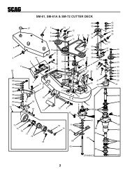
162412383725 48 46104920124447713041313270653244392817212223663703268693134272624364943412542152518181620354032439142045131113646752A6393360501535425581929565557516261145954A48", 52" & 61" CUTTER DECKS24 3BBSC214G7610576877
48", 52", & 61" CUTTER DECKS - CONT’DRef. PartNo. Number Description 48 52 61Ref. PartNo. Number Description 48 52 611 46852 Cutter Deck (Includes decals) X46615 Cutter Deck (Includes decals) X46611 Cutter Deck (Includes decals) X2 421058 Belt Cover, Front X421451 Belt Cover, Front X421299 Belt Cover, Front X3 04041-07 Flatwasher, 3/8" Special (.391x.938x.105) X X X4 04029-03 Wing Nut, 3/8-16 X X X5 481689 Anti-Scalp Wheel X481632 Anti-Scalp Wheel X X6 04003-26 Bolt, carriage 3/8-16 x 4" X X X7 422525 Anti-Scalp Wheel Bracket X422478 Anti-Scalp Wheel Bracket X X8 04017-27 Bolt, Hex Serrated Flange 3/8-16 x 1" X X X9 04040-10 Flatwasher, 5/8" (.688 x 1.75 x .134) X X X10 04021-05 Nut, Lock 3/8-16 Center Lock X X X11 461056 Discharge Chute X X461057 Discharge Chute X12 04001-09 Bolt, Hex Head 5/16-18 x 1" X X X13 04021-10 Nut, Hex Elastic Stop 5/16-18 X X X14 04017-16 Bolt, Hex Serrated Flange 5/16-18 x 3/4" X X X15 44078 “J” Rod X44101 “J” Rod X X16 45037 Idler Pivot Base X X X17 04001-46 Bolt, Hex Head 3/8-16 x 2-1/4" X X X18 48100-05 Bushing X X X19 481035 Nut, Special 1-1/16-18 X X X20 04019-03 Nut, Hex Serrated Flange 5/16-18 X X X21 46081 Idler Arm (Includes bushings &grease fittings)X X X22 43077 Spacer X X X23 43028 “J” Rod X X44078 “J” Rod X24 04021-09 Nut, Hex Elastic Stop 3/8-16 X X X25 48114-04 Grease Fitting X X X26 04041-08 Flatwasher, 3/4" X X X04041-08S Flatwasher, 3/4" Special X X X27 04050-02 Ring, Retaining 3/4" External “E” X X X28 48181 Pulley, Idler X X X29 43297 Spindle Bushing, Bottom X X X30 48924 Pulley, LH Spindle X X48753 Pulley, LH Spindle X31 48926 Tapered Hub, 1-1/8 Bore X X X32 04001-01 Bolt, Hex Head 1/4-20 x 3/4" X X X33 04001-41 Bolt, Hex Head 5/8-11 x 9-1/2" X X X34 48087 Belt, RH Blade Drive X48285 Belt, RH Blade Drive X48265 Belt, RH Blade Drive X35 04001-23 Bolt, Hex Head 3/8-16 x 4-1/2" X X X36 48550 Pulley, Idler Cutter Engagement X X X37 48923 Pulley, Double Groove X X48940 Pulley, Double Groove X38 48799 Belt, Blade Drive X481001 Belt, Blade Drive X48996 Belt, Blade Drive X39 04041-12 Flatwasher, 3/8" (.375 x 1.5 x .06) X X X40 48807 Spring, Idler Tension X X X41 48100-02 Bushing X X X42 46750 Idler Arm (Includes bushings &grease fittings)X X43 45329 Idler Pivot Base X X X44 04001-97 Bolt, Hex Head 5/8-11 x 3" X X X45 43282 Spacer X X46 04020-16 Nut, Hex 5/8-18 UNF X X X47 48763 Rod End X X X48 461036 Push Arm (Includes 25, 46, 47, and 49) X X X49 48100-06 Bushing X X X50 45332 Push Arm Shaft X X X51 46631 Spindle Assembly X X X52 43298 Spindle Shaft X X X53 481024 Seal, Top X X X54 481022 Bearing Assembly (1 required per spindle) X X X55 48667 Relief Fitting, Tapered Spindle X X X56 43294 Spindle Housing X X X57 481025 Seal, Bottom X X X58 43312 Spacer, Outside X X X59 43296 Spacer, Inside X X X60 04063-08 Key, 1/4 x 1/4 x 2" X X X61 04001-10 Bolt, Hex Head 5/16-18 x 1-1/4" X X X62 43279 Spacer, Tapered Spindle X X X63 48110 Cutter Blade, 16-1/2" Standard X48184 Cutter Blade, 16-1/2" High Lift X48108 Cutter Blade, 18" Standard X48185 Cutter Blade, 18" High Lift X48111 Cutter Blade, 21" Standard X48304 Cutter Blade, 21" High Lift X64 481050 Spring, Discharge Chute X X X65 48786 Electric Clutch X X X66 04001-108 Bolt, Hex Head 5/16-18 x 4.25" X X X67 421616 Belt Cover, LH X421615 Belt Cover, RH X42889 Belt Cover, LH X42890 Belt Cover, RH X421292 Belt Cover, LH X421293 Belt Cover, RH X68 48924 Pulley, RH Spindle X X X69 04001-109 Bolt, Hex Head 1/4-20 x 1.375 Full Thread X X X70 * Nut, Hex 5/8-11 UNC X X X71 04050-05 Ring, Retaining 1-1/8" External “E” X X X72 46963 Idler Arm (Includes bushings &grease fittings)X73 04001-51 Bolt, Hex Head 3/8-16 X 3 3/4" X74 04030-04 Lockwasher 3/8 X75 43369 Nut, 3/8-16 Special W/Washer X76 48100-16 Bushing, Anti-Scalp Wheel X48100-15 Bushing, Anti-Scalp Wheel X X77 461086 Anti-Scalp Wheel Assembly X(Includes item #'s 5, 6, 7, 10, & 76)17
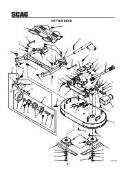
CUTTER DECK CONTROLS 48", 52" & 61" DECKS109813115745121518173517631935195125232222332521252316220143414292021622437322726142326293614302931143048" DECK292814SC215G18
CUTTER DECK CONTROLS 48", 52", & 61" DECKS - CONT’DRef. Part 48 52 61No. Number Description1 45524 Bellcrank, Lift - Right Front X X X2 48100-05 Bushing X X X3 45527 Lift Link X X X4 43180 Bushing X X5 04050-01 Retaining Ring, 5/8" External “E” X X6 45610 Lift Arm Weldment X45523 Lift Arm Weldment X X7 04017-17 Bolt, Serrated Flange Hex Head 5/16-18 x 1" X X X8 46384 Height Adjustment Lever (Includes grip) X X X9 48093 Grip, Lever Lift X X X10 44065 Rod, Cutter Deck Lock X X X11 48053 Spring, Deck Lift Index X X X12 04060-01 Roll Pin, 5/32 x 3/4" X X13 42887 Lock, Rod Guide X X X14 04019-04 Nut, Serrated Flange Hex 3/8-16 X X X15 04019-03 Nut, Serrated Flange Hex 5/16-18 X X16 48114-04 Grease Fitting X X X17 04017-05 Bolt, Serrated Flange Hex Head 1/4-20 x 3/4" X X18 42828 Strip, Height Adjustment X X X19 04019-02 Nut, Serrated Flange Hex 1/4-20 X X20 04041-08S Flatwasher, 3/4" (.766 x 1.250 x.075) X X21 04050-02 Ring, Retaining 3/4" External “E” X X22 04021-09 Nut, Elastic Stop 3/8-16 X X X23 04040-09 Flatwasher, 5/8" (.656 x 1.312 x .075) X X X24 45313 Bellcrank, Lift - Left Front X X X25 43271 Swivel Joint - LH THD X X X26 04004-18 Adjustment Stud X04004-15 Adjustment Stud X X27 04040-10 Flatwasher, 5/8" (.688 x 1.75 x .134) X X X28 48540 Chain X X29 04001-20 Bolt, Hex Head 3/8-16 x 1-1/2" X X X30 04020-09 Nut, Hex 5/8-11 X X X31 43270 Swivel Joint - RH X X X32 481045 Spring, Deck Lift X32 48953 Spring, Deck Lift X X33 45427 Bellcrank X X X34 04063-15 Key, 3/16 x 3/16 x .75" X X X35 48114-05 Grease Fitting X X36 421585 Link, Deck Support X37 04001-45 Bolt, Hex Head 3/8-16 x 2" X X X* Common hardware which should be purchased locally. All bolts Grade 5 plated, all other fasteners zinc plated.19
162019SHEET METAL COMPONENTS53515421 5010142310265261241015251225256510 10894 5 4 62510 17 27251433143029925646532672325(52" & 61" only)66(48" only)35297 5522575656A63(52" & 61" only)121374025103934 285841 363159116860 321818A6233 134442434838454647494542SC216G20
SHEET METAL COMPONENTS - CONT’DRef. PartNo. Number Description 48 52 61Ref. PartNo. Number Description 48 52 611 48100-08 Bushing X X X2 48114-04 Grease Fitting X X X3 43257 Bushing, Spring Keeper X X X4 04062-02 Hair Pin, .08 Diameter x 1-3/16" X X X5 04041-07 Flatwasher, 3/8" (.391 x .738 x .105) X X X6 44062 Rod, Foot Plate Latch X X X7 481086 Cable, Seat Stop X X X8 421589 Foot Plate X42764 Foot Plate X X9 481049 Hinge X X X10 04003-12 Bolt, Carriage 5/16-18 x 3/4" X X X11 04001-08 Bolt, Serrated Flange HexHead 5/16-18 x 3/4"X X X12 421251 Kick Plate X X X13 48746 Neutral Return Spring X X X14 04021-10 Nut, Elastic Stop 5/16-18 X X X15 461085 Fender Assembly, RH (with decal) X X X16 04001-73 Bolt, Hex Head 5/16-18 x 3-3/4" X X X17 04003-04 Bolt, Carriage 5/16-18 x 1" X X X18 421411 Retainer, Neutral Spring, LH X X X18A 421412 Retainer, Neutral Spring, RH X X X19 45405 Seat Switch Bracket X X X20 48463 Spring X X X21 04064-04 Clevis Pin X X X22 04017-15 Bolt, Serrated Flange HexHead 5/16-18 x 1/2"X X X23 04062-02 Hair Pin, Cotter X X X24 481532 Seat Assembly X481606 Seat Assembly w/Adjuster Rails X X25 04019-03 Nut, Serrated Flange Hex 5/16-18 X X X26 46754 Seat Base X X X27 04021-08 Nut, Elastic Stop 1/4-20 X X X28 04021-09 Nut, Elastic Stop 3/8-16 X X X29 04019-02 Nut, Serrated Flange Hex 1/4-20 X X X30 04017-06 Bolt, Serrated Flange Hex Head 1/4-20 x 1" X X X31 04001-31 Bolt, Hex Head 3/8-16 x 2-1/2" X X X32 04001-15 Flatwasher, 5/16" (.313 x .875 x .083) X X X33 481704 Seat Spring X X X34 421198 Fender Panel, LH X X X35 48566 Cable, Seat Stop X X X36 48464 Ball Joint, Neutral X X X37 45971 Fender , LH X X X38 46392 Caster Wheel Yoke Assembly X X X(Assembly not available for <strong>SSZ</strong>-LT)39 04066-01 Quick Pin X X X40 45325 Caster Wheel Yoke X X X451014 Caster Wheel Yoke (<strong>SSZ</strong>-LT) X X X41 04021-07 Nut, Elastic Stop 1/2-13 X X X42 43041 Spacer X X X43 04001-80 Bolt, Hex Head 1/2-13 x 6-1/2" X X X44 48537 Wheel Assembly, Complete X X X45 48006-07 Retainer X X X46 48537-02 Tire Only X X X47 48537-03 Rim Only X X X48 43022 Sleeve X X X49 48006-06 Roller Bearing X X X50 48717 Seat Switch X X X51 481532-01 Seat, Back Cushion X X X52 481532-02 Seat, Bottom Cushion X X X53 481532-03 Arm Pad, RH X X X54 481532-04 Arm Pad, LH X X X55 481474 Neutral Interlock Switch X X X56 422535 Neutral Lock Bracket, RH X X X56A 422536 Neutral Lock Bracket, LH X X X57 04017-24 Bolt, Serrated Flange HexHead 5/16-18 x 2-3/4"X X X58 43240 Spacer, Neutral Spring X X X59 43258 Spacer, Neutral Lock Bracket X X X60 04020-14 Nut, Hex 3/8-24 UNF X X X61 48704-06 Bolt, Hex Head w/Washer, 1/4-20 x 3/4" X X X62 04001-99 Bolt, Hex Head 3/8-24 x 6-1/2", UNF X X X63 46570 Seat Adjustment, Track Set X X X64 48030-09 Cable Clamp, .50 ID X X X65 04001-09 Bolt, Hex Head 5/16-18 x 1" X X X66 04017-16 Bolt, Serrated Flange Hex Head 5/16-18 x 1" X67 * Bolt, Hex Head 1/4-20 x 1.25" X X X68 * Lockwasher, 5/16" X X X69A 461083 Main Frame Assy. X69B 461084 Main Frame Assy. X X* Common hardware which should be purchased locally. All bolts Grade 5 plated, all other fasteners zinc plated.21
HYDRAULIC COMPONENTS15 1 21921A403620A13411735398181097652 141 1542634 22292423252893832738312922164030343238283438 37 103611 1211213320193935SC217G22
HYDRAULIC COMPONENTS - CONT’DRef. Part 48 52 61No. Number Description1 04030-03 Lockwasher, 5/16" X X X2 04040-04 Flatwasher, 5/16" (.344 x .688 x .065) X X X3 04017-05 Bolt, Serrated Flange Hex Head 1/4-20 x 3/4" X X X4 48790 Pump, Pulley X X X5 48791 Tapered Hub, 15 mm Bore X X X6 481696 Fan X X X7 421209 Washer, Back-up X X X8 04050-13 Snap Ring X X X9 04010-19 Capscrew 1/4-20 x 1/2" X X X10 04063-14 Key, 5 mm x 5 mm x 25 mm X X X11 04001-12 Bolt, Hex Head 5/16-18 x 1-3/4" X X X12 04001-96 Bolt, Hex Head 5/16-18 x 4-1/2" X X X13 04001-95 Bolt, Hex Head 5/16-18 x 5" X X X14 04001-94 Bolt, Hex Head 5/16-18 x 7-1/2" X X X15 04020-03 Nut, Hex 5/16-18 X X X16 04001-132 Bolt, Hex Head 3/8-16 x 4", grade 8 X X X17 48878 Spacer X X X18 48875 Gear X X X19 04021-18 Nut, Elastic Stop 3/8-16 X X X20 48784 Pump, LH (Includes spacers) X X X20A 48785 Pump, RH (Includes spacers) X X X21 481578 Axle, LH (Includes brake lever) X X X21A 481577 Axle, RH (Includes brake lever) X X X22 48350-09 Elbow, 90 Degree 9/16-18 JIC to 9/16-18 “O” Ring X X X23 48860 Oil Tank Reservoir X X X24 48894 Cap, Oil Reservoir X X X25 421208 Strap, Oil Reservoir X X X26 04015-14 Soc. Head Capscrew, 1/4-20 x 1-1/4" X X X27 04021-08 Nut, Elastic Stop 1/4-20 X X X28 48485-01 Elbow, 45 Degree 3/4-16 JIC to 3/4-16 “O” Ring X X X29 48603-06 “O” Ring, 5/64 x 15/32 ID X X X30 48872 Hose Assembly, Filter Inlet X X X31 48604-02 Plug, 3/4-16 “O” Ring X X X32 48462-02 Head, Oil Filter X X X33 48462-01 Oil Filter, Special X X X34 48871 Hose Assembly X X X35 48603-04 “O” Ring, 3/32 x 3/4 ID X X X36 48603-03 “O” Ring, 1/16 x 3/8 ID X X X37 48810-01 1/2" T-fitting, 3/4-16 JIC to 3/4-16 “O” Ring X X X38 48603-02 “O” Ring, 3/32 x 5/8 ID X X X39 48572-02 Tube Union 3/4-16 JIC to 7/8-14 “O” Ring X X X40 48350-10 Elbow, 90 Degree 9/16-18 JIC to 7/16-20 “O” Ring X X X41 HG50267 “O” Ring X X X42 481090 Gasket, Hydraulic Tank Cap X X X43 481507 Filler Neck Insert X X X* Common hardware which should be purchased locally. All bolts Grade 5 plated, all other fasteners zinc plated.23
BDU-10L HYDRAULIC PUMP101649323015127156178121811152OverhaulSEALKIT291714201925262420282721221323SC226GRef. PartNo. Number Description1 HG2513038 Pump Shaft Kit2 HG2003016 Wire Retaining Ring3 HG2003043 Ball Bearing4 HG2003018 Spacer5 HG9008000-0128 Lip Seal (16 x 35 x 7)6 HG2003052 Retaining Ring7 HG2003023 Cradle Bearing8 HG9008000-126 Lip Seal (12 x 35 x 7)9 HG2003005 Trunnion Arm10 HG2000015 Slot Guide11 HG2513020 Transmission Housing Kit RHHG2513003 Transmission Housing Kit LH12 HG2003044 Thrust Ball Bearing Assembly13 HG9008000-0127 Lip Seal (15 x 24 x 7)14 HG2003032 Motor Shaft15 HG2003017 Block Thrust WasherRef. PartNo. Number Description16 HG2003087 Variable Swash Plate17 HG70079 BDP-10L Block Assembly18 HG9004800-2506 Pin ST Holder19 HG2513006 Center Section Kit20 HG2510027 Check Valve Kit21 HG2510011 Charge Relief Kit22 HG9007314-0808 Socket Head Cap Screw23 HG2513011 Bypass Valve Kit24 HG9004101-1340 O-Ring25 HG2513027 Charge Pump Cover26 HG50273 Gerotor Assembly27 HG50095 Capscrew (6mm x 20")28 HG2003060 Center Section Gasket29 HG2513013 Overhaul Seal Kit30 HG2000025 Spring Block24
AXLE ASSEMBLY21718191615201421221116681313125109478BRAKE ASS'Y.FORMODEL # 48109836363526232827262334BRAKE ASS'Y.FORMODEL # 4810973133303229 28272526243133 3230 293426352524SC225GRef. PartNo. Number Description1 HG62768 Axle Housing Assembly2 HG44533 Hydro Mount Housing3 HG44358 Splined 72 Tooth Final Drive Gear4 HG62681 Axle Shaft Assembly5 HG44366 Bolt, 1/4-20 x 2-1/2" Hex Head6 HG44359 E-Ring .8757 HG50263 Oil Seal, 1.25 x .6258 HG44147 Ball Bearing, .62 ID x 1.38 x .449 HG44371 Washer, HT .62 ID x 1.0 OD x .05 Thick10 HG44351 Brake Shaft (Splined)11 HG50419 Splined Reduction Gear, 17 Tooth12 HG50420 Splined 60 Tooth Gear13 HG44371 Washer, HT .62 ID x 1.0 OD x .05 Thick14 HG9001214-3700 Ball, 3/8" Diameter15 HG50223 Gasket, Housing16 HG44269 Pin, Spring 3/16" x 1/2" x 12" Long17 HG23747 Mounting Spacer18 HG44232 Bearing, Spacer19 HG50267 O-RingRef. PartNo. Number Description20 HG44232 Ball Bearing, 15mm x 35mm x 11mm21 HG44353 Input Gear, 11 Tooth22 HG44354 Retaining Ring23 HG44143 Key, Hi Pro 3/16 x 5/824 HG44132 Puck, Brake25 HG44134 Plate, Puck26 HG23770 Brake Spacer27 HG62589 Brake Yoke Assembly28 HG44276 Bolt, 1/4-20 x 1-1/2" W/Patch29 HG44130 Washer, 7/16 x 7/8 OD x .06 HT30 HG44142 Nut, Castle 5/16-24 PL31 HG44101 Pin, Cotter32 HG44127 Pin, Brake Actuating33 HG44094 Arm, Brake Actuator (LH Assy.)33 HG44613 Arm, Brake Actuator (RH Assy.)34 HG44612 Bolt, 1/4-20 x 2-1/2"35 HG23711 Spacer, Torsion Spring36 HG44090 Disc, Brake25
TRACTION DRIVE COMPONENTS143255615560598265125454313101759141658311913515723 218 245622 201544211240532712411173049 48361429334644 45 414244475041 52 43442868353438393769SC218GA32626
TRACTION DRIVE COMPONENTSRef. PartNo. Number Description 48 52 611 481116 Engine 18 hp Kohler CV For <strong>SSZ</strong>-18CV X481117 Engine 20 hp Kohler CV For <strong>SSZ</strong>-20CV X X X481118 Engine 22 hp Kohler CV For <strong>SSZ</strong>-22CV X X X2 48058-03 Fuel Hose X X X3 48633 Muffler Clamp X X X4 48964 Tube, Exaust X X X5 * Kohler Fittings, Purchase From Kohler X X X6 48030-09 Clamp, 50 ID X X X7 04021-09 Nut, 3/8-16 Elastic Stop X X X8 48402-06 Extention, 2.50" X X X9 48257 Pipe Cap X X X10 04017-19 Bolt, 5/16-18 x 1-1/2" Serr. Flng. Hex Head X X X11 04003-05 Bolt, 7/8-16 x 1.50" Carriage X X X12 04019-03 Nut, Serrated Flange Hex Head 5/16-18 X X X13 04003-12 Bolt, Carriage 5/16-18 x 3/4" X X X14 04040-15 Flatwasher, 5/16" (.313 x .875 x .083) X X X15 45479 Fender, LH X X X16 421197 Battery Box X X X17 04003-01 Bolt, Carriage 1/4-20 x 6" X X X18 04029-01 Wing Nut, 1/4-20 X X X19 04003-04 Bolt, Carriage 5/16-18 x 1" X X X20 04019-02 Nut, Serrated Flange Hex 1/4-20 X X X21 04003-02 Bolt, Carriage 1/4-20 x 3/4" X X X22 421624 Belt Guard X X X23 48059-01 Fuel Hose Clamp X X X24 48661 Rubber Pad X X X25 42392 Battery Cover X X X26 48099 Pad, Battery Cover X X X27 48792 Pulley X X X28 48790 Pulley, Pump X X X29 04063-06 Key, 1/4 x 1/4 x 1-1/2" X30 04041-07 Flatwasher, 3/8" (.391 x .938 x .105) X X X31 04110-01 U-Nut, 1/4-20 X X X32 04021-10 Nut, Elastic Stop 5/16-18 X X X33 461073 Electric Clutch X X X34 481716 Rubber Pad, Clutch Stop X X XRef. PartNo. Number Description 48 52 6135 422533 Backing Plate X X X36 04001-12 Bolt, Hex Head 5/16-18 x 1-3/4" X X X37 04001-93 Bolt, Hex Head 7/16-20 x 2.25 (<strong>SSZ</strong> BV) X X X37A 04001-103 Bolt, Hex Head 7/16-20 x 3.00" (<strong>SSZ</strong> CV) X X X38 04030-05 Lockwasher, 7/16" X X X39 04041-28 Flatwasher,Retainer X X X40 48181 Idler, Pulley X X X41 04001-21 Bolt, Hex Head 3/8-16 x 1.75" X X X42 45650 Pivot Weldment, Idler Arm X X X43 48114-04 Grease Fitting X X X44 04019-04 Nut, Serrated Flange Hex 3/8-16 X X X45 48961 Spring, Pump Drive Idler X X X46 04003-12 Bolt, Carriage 5/16-18 x 3/4 X X X47 04019-03 Nut, Serrated Flange Hex 5/16-18 X X X48 04050-05 Ring, Retaining 1.125 Diameter External “E” X X X49 48100-02 Bushing, 1.125 Sintered X X X50 46755 Idler Arm Weldment, Pump Drive X X X51 48309 Bushing, Fuel Tank Valve X X X52 48760 Belt, Pump Drive X X X53 43248 Spacer, Crankshaft X X X54 48651 Fuel Tank (Includes shut-off valve) X X X55 481556 Fuel Tank Cap X X X56 48308 Fuel Shut-off Valve X X X57 42944 Fuel Tank Strap, Long X X X58 42945 Fuel Tank Strap, Short X X X59 48657 Rubber Pad X X X60 46505 Fender Assembly, RH (with decal) X X X61 04010-10 Screw, Machine 1/4-20 x 2" Phillips Head X X X62 04017-19 Bolt, 5/16-18 x 1-1/2" Serr.Flng. Hex Head X X X63 04003-05 Bolt, Carriage 7/8-16 x 1.50" X X X64 04021-09 Nut, Elastic Stop 3/8-16 X X X65 48030-09 Clamp, .50 ID X X X66 * Kohler Fittings, Purchase From Kohler X X X67 48600-01 Elbow, Street X X X68 422534 Backing Plate X X X69 04063-24 Key, 1/4 x 1/4 x 2.75 X X X* Kohler hardware which should be purchased from an authorized Kohler Dealer.27
BRAKE AND STEERING CONTROLS593658424754 55563820392053225135483350247723202021252260122220222626A21494466A484618 17 19 16847 154319 14449276262A2828A2755 55A52313857671032131255A11372828A304041612929A3422 452173774 75 6969A36768756672 71 70477 647663 57SC219G28
BRAKE AND STEERING CONTROLS - CONT’DRef. PartNo. Number Description 48 52 611 481503 Drive Wheel Assembly X1 481504 Drive Wheel Assembly X X1 481607 Drive Wheel Assembly (<strong>SSZ</strong>-LT-48) X1 481608 Drive Wheel Assembly (<strong>SSZ</strong>-LT) X X2 481619 Tire Only X X X3 48321-04 Rim Only X3 48958-03 Rim Only X X X4 04028-01 Lug Nut, 1/2-20 X X X5 481578 Axle, LH (Includes brake lever) X X X5A 481577 Axle, RH (Includes brake lever) X X X6 48784 Pump, LH X X X6A 48785 Pump, RH X X X7 45464 Dump Valve, Lever Weldment X X X8 421212 Bracket, Mounting X X X9 04062-01 Hair Pin X X X10 04001-95 Bolt, Hex Head 5/16-18 x 5" X X X11 * Flatwasher, 5/16" X X X12 * Lockwasher, 5/16" X X X13 * Nut, Hex 5/16-18 X X X14 45462 Pump Weldment Shaft X X X15 421203 Clamp Plate X X X16 48829 Block, Pump Control X X X17 48796 Bushing, Self Align X X X18 421204 Bracket, Bearing X X X19 * Bolt, Hex Head 3/8-16 x 1" X X X20 * Nut, Elastic Stop 3/8-16 X X X21 * Bolt, Hex Head 3/8-16 x 1-1/2" X X X22 04041-07 Flatwasher, 3/8" Special X X X23 48544 Ball Joint, LH Thread X X X24 43246 Link, Turnbuckle X X X25 48464 Ball Joint, RH Thread X X X26 45895 Lever, Pump Transfer LH X X X26A 45896 Lever, Pump Transfer RH X X X27 48114-04 Grease Fitting X X X28 48100-06 Bushing, LH X X X28A 48100-05 Bushing, RH X X X29 45897 Control Lever, LH X X X29A 45898 Control Lever, RH X X X30 * Bolt, Hex Head 5/16-18 x 1-1/2" X X X31 04019-03 Nut, Serrated Flange Hex 5/16-18 X X X32 421145 Bar Control Lever X X X33 461037 Control Handle X X X34 04017-27 Bolt, Serrated Flange Hex Head 3/8-16x1" X X X35 481599 Grip, Control Handle X X X36 45482 Lever Weldment, Parking Brake X X XRef. PartNo. Number Description 48 52 6137 45551 Cam Weldment, Parking Brake X X X38 422459 Plate, Parking Brake X X X39 421266 Latch, Brake X X X40 43256 Swivel Joint X X X41 44080 Rod, Brake X X X42 48840 Cable Assembly, Parking Brake X X X43 421238 Plate, Coupler X X X44 04017-05 Bolt, Serrated Flange Hex Hd 1/4-20 x 3/4" X X X45 04001-132 Bolt, Hex Head 3/8-16 x 4", grade 8 X X X46 04050-02 Ring, Retaining 3/4" External “E” X X X47 04019-02 Nut, Serrated Flange Hex 1/4-20 X X X48 * Bolt, Sertd. Flg. Hex Head 1/4-20 x 1-1/4" X X X49 04060-06 Roll Pin, 3/16 x 3/4" X X X50 * Nut, Hex 3/8-24 X X X51 * Bolt, Hex Head 3/8-16 x 2" X X X52 04041-12 Flatwasher, 3/8 (.375 x 1-1/2" x 16 ga.) X X X53 48050 Spring, Brake Lever X X X54 * Bolt, Carriage 3/8-16 x 1-1/2" X X X55 04021-18 Nut, Elastic Stop 3/8-16 X X X55A 04030-09 Lockwasher, 3/8" spring, grade 8X X X56 04017-16 Bolt, Serrated Flange HexHead 5/16-18 x 3/4"X X X57 04062-02 Hair Pin, 1/16" X X X58 * Nut, Elastic Stop 1/4-20 X X X59 48342 Grip, Parking Brake X X X60 * Bolt, Hex Head 5/16-18 x 1-1/2" X X X61 04021-10 Nut, Elastic Stop 5/16-18 X X X62 04041-08 Flatwasher, 3/4" X X X62A 04041-08S Flatwasher, 3/4" SpecialX X X63 HG44612 Bolt, 1/4-20 x 2-1/2 GR. 5 w/patch X X X64 HG44276 Bolt, 1/4-20 x 1-1/2 GR. 5 w/patch X X X65 04008-02 Bolt, Wheel Mounting X X X66 HG44127 Pins, Actuating X X X67 HG44132 Brake Puck X X X68 HG44134 Backing Plate X X X69 HG44093 Actuating Lever, RH X X X69A HG44613 Actuating Lever, LHX X X70 * Pin, Cotter X X X71 HG44142 Nut, Castle X X X72 HG44130 Washer, 7/16 x 7/8 OD x .06 HT X X X73 HG44090 Disc, Brake X X X74 HG44143 Key, Hi Pro 3/16 x 5/8 X X X75 HG23770 Brake Spacer X X X76 HG23711 Spacer, Torsion Spring X X X77 HG62589 Brake Yoke Assembly X X X78 04008-02 Wheel Stud X X X29
INSTRUMENT PANEL AND ELECTRICAL COMPONENTS126292827413127262541243015373936173837213182020A63314192211 123723241035341211216141398 32 475SC220G30
INSTRUMENT PANEL AND ELECTRICAL COMPONENTSRef. Part 48 52 61No. Number Description1 481116 Engine 18 hp Kohler CV (**) X481117 Engine 20 hp Kohler CV (**) X X481118 Engine 22 hp Kohler CV (**) X X2 48780 Choke Control X X X3 481070 Adapter X X XRef. Part 48 52 61No. Number Description4 421251 Kick Plate X X X5 48023 Hour Meter X X X6 48022 Ammeter X X X7 48798 Key Switch (Includes mounting hardware) X X X8 48017-04 Nut, Hex 5/8-32 X X X9 48017-02 Key & Ring Assembly X X X10 42413 Bracket, Fuse Holder X X X11 04031-01 Lockwasher, #10 External Tooth X X X12 04020-07 Nut, Hex #10-32 X X X13 04010-11 Screw, Phillips Washer Head #10-32 x 1-1/2" X X X14 04010-01 Screw, Phillips Washer Head #10-32 x 1/2" X X X15 48015-01 Overflow Tube X X X16 48879 Throttle Control X X X17 481269 Wire Harness X X X18 48787 Switch, Mower Engagement Electric Clutch X X X19 48788 Relay X X X20 422536 Neutral Lock Bracket, RH X X X20A 422535 Neutral Lock Bracket, LH X X X21 48522 Switch Neutral Lock X X X22 04003-12 Bolt, Carriage 5/16-18 x .75" X X X23 04021-10 Nut, Elastic Stop 5/16-18 X X X24 04019-03 Nut, Serrated Flange Hex 5/16-18 X X X25 48015 Battery X X X26 04001-44 Bolt, Hex Head 1/4-20 x 1/2" X X X27 04020-02 Nut, Hex 1/4-20 X X X28 48126 Rubber Boot X X X29 48029-13 Battery Cable, 25" Red X X X30 48029-11 Battery Cable, 27" Black X X X31 04017-19 Bolt, Serrated Flange Hex Head 5/16-18 x 1.50" X X X32 48017-03 Lockwasher, 5/8" Internal X X X33 48787-01 Nut, Hex 1/2-27 X X X34 48298 Fuse, Blade Type 20 amp X X X35 04021-01 Nut, Elastic Stop #10-32 X X X36 461073 Electric Clutch X X X37 48030-09 Clamp X X X38 04003-12 Bolt, Carriage 5/16-18 x 3/4" X X X39 04021-10 Nut, Elastic Stop 5/16-18 X X X40 04031-09 Lockwasher, 5/16" Internal Tooth X X X41 481275 Wire Harness W/Relay X X X* Common hardware which should be purchased locally. All bolts Grade 5 plated, all other fasteners zinc plated.** Contact engine manufacturer for replacement engine.31
BLACKBATTERYELECTRICAL WIRING DIAGRAM - KOHLER+ELECTRICCLUTCHBLUE-REDBLACKBLACKRELAYBLACKREDREDREDGREENREDBLACKSTARTERBLACKBLACKGREENYELLOWTO MAGNETO (WHITE)TO ALTERNATOR (PURPLE)BLACKBLUE/REDENGINE HARNESSCONNECTORSBLACKREDWHITEPURPLE/REDBLACKYELLOWREDREDCLUTCHSWITCHREDGREENLH NEUTRALINTERLOCK SWITCHBLACKGREENRELAYBLACKREDBLACKREDGREENBLACKBLACKGREENYELLOWGREENREDBLACKBLACKGREENBLACKBLACKRH NEUTRALINTERLOCKSWITCHBLACKREDREDBLACKREDBLACKBLACKREDREDBLACKREDYELLOWSEATINTERLOCKSWITCHFUSEBATTERY CABLESBLACKREDFUSEGROUND TO KILLMAGNETOREDBLACKYELLOWKEYSWITCHYELLOWREDYELLOWPOSITIVE TO START- CHARGEHOURMETERBLACKYELLOWAMMETERINSTRUMENT PANELSC221G32
REPLACEMENT DECALS48556 - Size 12" x 3.25"ZERO - TURN48859 - Size 11.5" x 5.5"48623 - Size 12" x 3.25"HEAVY DUTYCOMMERCIAL48318-48"48319-52"48320-61" 48404484044807248104133
REPLACEMENT DECALSPARKING BRAKEOFFCAUTIONAVOID INJURY FROMBURNS. SHUT OFFENGINE BEFOREREMOVING FUELTANK CAP.ON481137481137WARNINGINSTALL BELT COVER BEFOREOPERATING MACHINEREAD OPERATOR'S <strong>MANUAL</strong> 481039481039WARNINGROTATING BLADES AND BELTSKEEP HANDS, FEET & CLOTHING CLEARKEEP ALL GUARDS IN PLACESHUT OFF ENGINE & DISENGAGE BLADECLUTCH BEFORE SERVICINGCLEAR AREA OF DEBRIS BEFORE MOWINGUSE CAUTION IN DIRECTING DISCHARGEKEEP BYSTANDERS, CHILDREN & PETS AWAYREAD INSTRUCTION <strong>MANUAL</strong> BEFORE OPERATINGDO NOT OPERATE WITHOUT DISCHARGE CHUTE, MULCHINGKIT, OR ENTIRE GRASS CATCHER INSTALLED 481040FOR CORRECT BELT TENSIONTIGHTEN NUT UNTIL SPRINGALIGNS WITH BRACKET EDGESEE OPERATORS <strong>MANUAL</strong>4887348873481040STARTFFORWARDONOFFFASTMOWER DECKPULL OUT TO ENGAGEFFORWARDNNEUTRALRREVERSECAUTIONKEEP BYSTANDERS AWAYSTART / DRIVEPROCEDUREENGAGE PARKING BRAKEDISENGAGE MOWER DECK DRIVEMOVE CONTROL HANDLESTO NEUTRAL LOCK POSITIONSTART ENGINERELEASE PARKING BRAKESELECT FORWARD ORREVERSE SPEED WITHHYDRO CONTROL HANDLESRSLOWPUSH INTO DISENGAGECAUTIONBEFORE OPERATINGREAD OPERATINGS<strong>MANUAL</strong> AND SAFETYINSTRUCTIONS481685NNEUTRALRREVERSE48168534
REPLACEMENT DECALSCAUTION:SPRING TENSION ON IDLERSEE OPERATOR'S <strong>MANUAL</strong>BEFORE DISASSEMBLY4810994810994810424807148825 - Size 8.5" x 2"MANUFACTURED UNDER ONE OR MOREOF THE FOLLOWING PATENTS:4,487,006 4,991,3824,885,903 4,998,9484,920,733 4,118,6174,967,543PATENTS PENDING486564865635
LIMITED WARRANTY-COMMERCIAL EQUIPMENTAny part of the <strong>Scag</strong> commercial mower manufactured by <strong>Scag</strong> <strong>Power</strong> <strong>Equipment</strong> and found, in the reasonable judgmentof <strong>Scag</strong>, to be defective in materials or workmanship, will be repaired or replaced by an Authorized <strong>Scag</strong> Service Dealerwithout charge for parts and labor. This warranty is limited to the original purchaser and is not transferable. Proof ofpurchase will be required by the dealer to substantiate any warranty claims. All warranty work must be performed by anAuthorized <strong>Scag</strong> Service Dealer.This warranty is limited to the following specified periods from the date of the original retail purchase for defects inmaterials or workmanship:* Wear items including drive belts, blades, hoses and tires are warranted for 90 days.* Batteries are covered for 90 days.* Frame, deck, and structural components including oil reservoir, fittings, and oil coolerare warranted for 1 year.* Engines and electric starters are covered by the manufacturer’s warranty period.* Drive system components are warranted for 1 year by the component manufacturer, inconjunction with <strong>Scag</strong> <strong>Power</strong> <strong>Equipment</strong>. (Excluding fittings, hoses, cooling system,oil reservoir, drive belts).* Electric clutch components are warranted for 1 year.* Cutter Spindle Assemblies 46631 have a Limited Warranty for three years (Parts andlabor 1st year; Parts only 2nd and 3rd year).Any <strong>Scag</strong> product used for rental purposes is covered by a 90 day warranty.The <strong>Scag</strong> mower, including any defective part must be returned to an Authorized <strong>Scag</strong> Service Dealer within the warrantyperiod. The expense of delivering the mower to the dealer for warranty work and the expense of returning it to the ownerafter repair will be paid for by the owner. <strong>Scag</strong>’s responsibility is limited to making the required repairs and no claim ofbreach of warranty shall be cause for cancellation or rescission of the contract of sale of any <strong>Scag</strong> mower.This warranty does not cover any mower that has been subject to misuse, neglect, negligence, or accident, or that hasbeen operated in any way contrary to the operating instructions as specified in the Operator’s Manual. The warrantydoes not apply to any damage to the mower that is the result of improper maintenance, or to any mower or parts that havenot been assembled or installed as specified in the Operator’s Manual and Assembly Manual. The warranty does notcover any mower that has been altered or modified, changing performance or durability. In addition, the warranty doesnot extend to repairs made necessary by normal wear, or by the use of parts or accessories which, in the reasonablejudgment of <strong>Scag</strong>, are either incompatible with the <strong>Scag</strong> mower or adversely affect its operation, performance or durability.<strong>Scag</strong> <strong>Power</strong> <strong>Equipment</strong> reserves the right to change or improve the design of any mower without assuming any obligationto modify any mower previously manufactured.All other implied warranties are limited in duration to the one (1) year warranty period or ninety (90) days for mowers usedfor rental purpose. Accordingly, any such implied warranties including merchantability, fitness for a particular purpose,or otherwise, are disclaimed in their entirety after the expiration of the appropriate one year or ninety day warranty period.<strong>Scag</strong>’s obligation under this warranty is strictly and exclusively limited to the repair or replacement of defective parts and<strong>Scag</strong> does not assume or authorize anyone to assume for them any other obligation. Some states do not allow limitationson how long an implied warranty lasts, so the above limitation may not apply to you.<strong>Scag</strong> assumes no responsibility for incidental, consequential or other damages including, but not limited to, expense forgasoline, expense of delivering the mower to an Authorized <strong>Scag</strong> Service Dealer and expense of returning it to the owner,mechanic’s travel time, telephone or telegram charges, rental of a like product during the time warranty repairs are beingperformed, travel, loss or damage to personal property, loss of revenue, loss of use of the mower, loss of time or inconvenience.Some states do not allow the exclusion or limitation of incidental or consequential damages, so the abovelimitation or exclusion may not apply to you.This warranty gives you specific legal rights, and you may also have other rights which vary from state to state.
© 1997SCAG POWER EQUIPMENTDIVISION OF METALCRAFT OF MAYVILLE, INC.PART NO. 03045PRINTED 10/97PRINTED IN USA