Control of nanoparticle size in RF thermal plasma synthesis of ...
Control of nanoparticle size in RF thermal plasma synthesis of ...
Control of nanoparticle size in RF thermal plasma synthesis of ...

You also want an ePaper? Increase the reach of your titles
YUMPU automatically turns print PDFs into web optimized ePapers that Google loves.
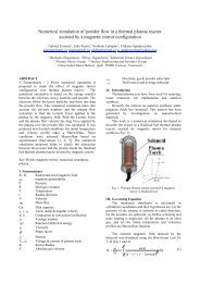
Table 1. Process parameters and filter yield for differenttests with solid precursor.Name <strong>of</strong>the test1A 2B 3A 4A 5A 6APrecursortypeA B A A A AUppercurta<strong>in</strong> gas 0 3 3 10 0 0(m³/h)Lowercurta<strong>in</strong> gas 0 0 0 0 0 12(m³/h)Feed rate(g/m<strong>in</strong>)6 6.5 2.3 1 N.A. N.A.Filter yield(g/h)N.A. 21 25 25 5 21N.A. = Not AvailableFigure 1. Schematic <strong>of</strong> the <strong>plasma</strong> <strong>nanoparticle</strong>s <strong>synthesis</strong>system.A Tekna Plasma Systems powder feeder PF400 hasbeen used for the <strong>synthesis</strong> <strong>of</strong> silica nanopowdersstart<strong>in</strong>g from a solid glass precursor, <strong>in</strong>ject<strong>in</strong>g powders<strong>in</strong> the <strong>plasma</strong> torch trough an <strong>in</strong>jection probe. Anelectrical oven has been used to pre-heat precursorsbefore <strong>in</strong>jection.A Tekna Plasma Systems suspension feeder SF-300has been used for the liquid precursor <strong>in</strong>jection us<strong>in</strong>gan atomization probe send<strong>in</strong>g atomized precursordroplets <strong>in</strong> the core <strong>of</strong> the <strong>plasma</strong> discharge by means<strong>of</strong> a carrier gas (Ar).3. Nanoparticle and precursor characterizationSize, morphology and composition <strong>of</strong> synthetizedpowders have been analysed. Specific surface area(SSA) analysis was carried out us<strong>in</strong>g a NOVA 2200eanalyser (Quantachrome Instruments), based on BETtheory [8]. Before nitrogen adsorption, samples weredried at 300°C and degassed. A mean diameter <strong>of</strong><strong>nanoparticle</strong>s can be evaluated specific surface areaassum<strong>in</strong>g spherical and dense particles and us<strong>in</strong>g thefollow<strong>in</strong>g relation:where D is the mean diameter and ρ is the density(≈2300 kg/m³ for the glass <strong>of</strong> fluorescent lamps, ≈2650kg/m³ for pure silica). A scann<strong>in</strong>g electron microscope(EVO 50 from ZEISS) was used to study the <strong>size</strong> andmorphology <strong>of</strong> precursor particles and <strong>of</strong> the produced<strong>nanoparticle</strong>s; analysis <strong>of</strong> the chemical composition <strong>of</strong>the particles was carried out us<strong>in</strong>g Energy-DispersiveX-ray Spectroscopy (EDS).(1)4. Nanosilica <strong>synthesis</strong> from solid precursorsMicrometric glass powders used as precursor wereobta<strong>in</strong>ed from gr<strong>in</strong>ded fluorescent lamps with differentmeshes (average diameter: precursor A = 38-75 μmprecursor B = 75-125 μm). The mercury content hasbeen removed from the glass powders before the<strong>plasma</strong> treatment, for safety reasons. EDS analysis <strong>of</strong>powders showed that they are ma<strong>in</strong>ly composed bySiO₂ and Na₂O with small fraction <strong>of</strong> other elements asmetallic oxides (O 52.40%, Na 10.87%, Mg 1.50%, Al1.14%, Si 30.19%, K 0.90%, Ca 2.99% by weight, withonly slight variations <strong>in</strong> different samples). Thesamples were heated at a temperature <strong>of</strong> 180°C for onehour <strong>in</strong> an oven to <strong>in</strong>crease the powder flowabilitydur<strong>in</strong>g <strong>in</strong>jection. Different tests for the production <strong>of</strong>silica <strong>nanoparticle</strong>s have been performed keep<strong>in</strong>g fixed<strong>plasma</strong> operat<strong>in</strong>g conditions and chang<strong>in</strong>g the curta<strong>in</strong>gas flow conditions, precursor feed rate and precursortype, as reported <strong>in</strong> Table 1. As a comparison betweendifferent tests, the amount <strong>of</strong> <strong>nanoparticle</strong>s collected <strong>in</strong>the sampl<strong>in</strong>g filter has been measured and normalizedwith respect to the duration <strong>of</strong> the test, thus obta<strong>in</strong><strong>in</strong>g amean collection rate <strong>in</strong> the sampl<strong>in</strong>g filter that will becalled “filter yield” <strong>in</strong> the next sections. Argon hasbeen used as carrier gas and <strong>plasma</strong> gas with a flowrate <strong>of</strong> 6 slpm and 13 slpm, respectively. Air was usedfor sheath gas, <strong>in</strong>jected with a flow rate <strong>of</strong> 60 slpm. Airhas also been used as curta<strong>in</strong> gas <strong>in</strong> the reactionchamber, with conditions reported <strong>in</strong> Table 1. Totalpower <strong>of</strong> the <strong>RF</strong> system was set to 30 kW and thereaction chamber operat<strong>in</strong>g pressure was set to 70 kPa.Only one test has been done with precursor B s<strong>in</strong>ce itslow vaporization efficiency <strong>in</strong>duced the formation <strong>of</strong>millimetric SiO₂ crystals <strong>in</strong> the chamber and near thetorch outlet.Tests with precursor A have been carried out fordifferent conditions <strong>of</strong> the curta<strong>in</strong> gas. As can be seen<strong>in</strong> Table 1 compar<strong>in</strong>g test 5A with other ones, an