UtiliTrak® Linear Guide - TEA Machine Components Inc.
UtiliTrak® Linear Guide - TEA Machine Components Inc.
UtiliTrak® Linear Guide - TEA Machine Components Inc.

You also want an ePaper? Increase the reach of your titles
YUMPU automatically turns print PDFs into web optimized ePapers that Google loves.
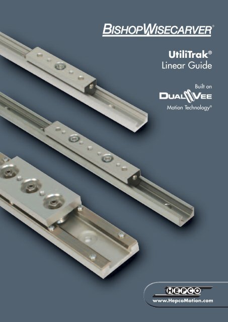
UtiliTrak ®<strong>Linear</strong> <strong>Guide</strong>Built onMotion Technology ®
For amendments & updates visit www.HepcoMotion.com and select literature buttonContentsIntroduction & Product Comparison Overview 1-33-Wheel Carriage Assemblies & Channel – PW/SW Series 4-74 and 5-Wheel Carriage Assemblies – SW Series 8-9Stainless Steel Composite Assembly & Channel 10-11System Adjustment 12Mounting Details 12Load Capacity 13Lubrication 13Accuracy 13Load/Life Calculations 13What’s Inside3, 4 or 5-wheel carriage* assemblies with the guide wheels mounted in-line roll along (and are captured within) the channelguide rail. For the 3 and 4-wheel carriage assemblies, the two outside guide wheels are concentric, while the centre wheelsare eccentric. The 5-wheel carriage assemblies feature concentric centre wheel and outer wheels with eccentric second andfourth wheels.Carriage assemblies are pre-set at the factory, but are easily field adjusted by rotating the eccentrically mounted centre guidewheels. This allows modification of running characteristics such as drag, breakaway force and preload.Each wheel carriage assembly includes a standard lubricator, which distributes a light coat of oil along the length of the channelduring normal operation. Lubrication of the channel increases life and speed capacity.*PW Series polymer and CR Series stainless steel composite wheel carriage assemblies available in 3-wheel configurationonly.
IntroducingUtiliTrak ® <strong>Linear</strong> <strong>Guide</strong>sThe UtiliTrak ® linear guide system from Bishop-Wisecarver is designed forapplications where low cost, easy installation and minimal maintenance requirementsare the primary design objectives. Constructedwith DualVee Motion Technology ® , UtiliTrak ®offers high reliability, easy installation and lowmaintenance in a sleek, compact design.Designed primarily for transport type applications, UtiliTrak ® is intendedfor use where load capacity, stiffness, and positional accuracy are lessdemanding than machine tool grade applications. UtiliTrak ® offers a low costalternative to recirculating ball guide technologies, which often require aconsiderable amount of surface preparation, adding significantly to the totalinstalled cost.UtiliTrak ® can be specified in three basic formats:• SW – Hardened and ground steelchannel with precision steelwheels.• PW – Aluminium alloychannel with polymerovermoulded wheels.• CR – Stainless steel track mounted toaluminium channel with stainless steelwheels.Open/<strong>Guide</strong>d Mounting ConfigurationSee page 2 for full specificationOpen ChannelVee ChannelFeatures and benefits• Antifriction operation• Low noise• Smooth running• High speed capacity• Unlimited travel lengths• High load capacity• Resistant to contamination
Product Comparison and OverviewFeatures SW Series UtiliTrak ® PW Series UtiliTrak ® CR Series Stainless SteelComposite UtiliTrak ®Channel/ChannelAssemblyOne-piece ground carbonbearing steel channel, runningsurface smooth to Ra 0.8µm,hardened steel raceways, RoHScompliant anti-corrosion plated.6063 – T6 aluminium alloychannelInduction heat treated 420stainless steel DualVee ® trackmounted to an extruded aluminumchannel52100 carbon steel, ground,High temp polymer overmouldedStudded DualVee ®<strong>Guide</strong> Wheelsdouble row, angular contactbearing arrangement, availablesealed or shielded, internalon a stainless steel bearingarrangement, built-in wiper capsat each end clear debris from the440C stainless steel, double row,angular contact bearingarrangement, sealedlubricationchannel surfaceMadeWellCrown Rollers52100 carbon steel, ground,double row, angular contactbearing arrangement, availablesealed or shielded, internallubricationHigh temp polymer overmouldedon a stainless steel single rowdeep groove bearing,built-in wiper caps at each endclear debris from the channelsurfaceWheel Sizes 1, 2 and 3 0, 1 and 2 1, 2 and 3Wheel CarriageAssembly3, 4 or 5-wheel configuration 3-wheel configuration only 3-wheel configuration onlyLubricator &Wiper AssemblyNylon end cap with felt lubricator,one lubricator assembly on eachend, synthetic oilNylon end cap with felt lubricator,one lubricator assembly on eachend, synthetic oilStainless steel stamped feltlubricator with synthetic oil,centrally located lubricatorLoad Capacity Up to 14,040N Up to 311N Up to 5,739NSpeeds Up to 5.5 m/s Up to 1.0 m/s Up to 5.5 m/sAcceleration Up to 49 m/s 2 Up to 29 m/s 2 Up to 49 m/s 2Key BenefitsHigh speeds, excellent loadcapacity, smooth antifrictionoperation, debris tolerantLowest installed cost in its class,corrosion resistant, low noise,lightweight, wear resistantHigh speeds, excellent loadcapacity, smooth antifrictionoperation, debris tolerant,corrosion resistant
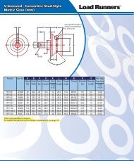
Wheel Carriage and Vee Channel AssemblyStudded DualVee ® <strong>Guide</strong> WheelWheel Carriage AssemblyLubricatorAssemblyChannelSW: Induction Hardened Carbon Bearing SteelPW: Precision Extruded AluminumMadeWell Crown Roller &Open Channel AssemblyCR Series Stainless SteelComposite AssemblyMadeWell Crown RollerStainless Steel DualVee ® TrackExtruded Aluminum Channel
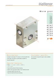
PW/SW Series 3-Wheel Carriage AssembliesPW Series• Vee style carriage assembly for PW Series aluminum channel• Light to medium duty transport applications• Extremely low noise• Lightweight and economicalDimensionsSW Series• Vee style carriage assembly for SW Seriessteel channel• Medium to heavy duty transport applications• High speed capability• Smooth antifriction operationUtiliTrak ®SizePW 4Part No.SW 1Part No. A B C DESocketSize F G0 UT0WPAP - 79.9 18 22 7.9 8 22 M4x0.71 UT1WPAP UT1WPA 113.5 24 26.3 8.8 10 40 M6x12 UT2WPAP UT2WPA 144.2 38 35 11.8 13 45 M8x1.253 - UT3WPA 201.3 55 50 15.8 15 60 M10x1.5All dimensions in mmLoad Capacity (Max)UtiliTrak ®SizeRadialF RAxialF AM PM YM RCPW Series Wheel CarriageRadialF RAxialF AM PM YM RCSW Series Wheel Carriage0 55 88 3 1.5 1 130 - - - - - -1 110 155 8 3 2 200 2440 719 18 30.5 7 56002 165 311 18 8 4 350 5300 1475 58 100 22.7 102003 - - - - - - 11800 5100 229 346 118 21600Loads in N, Moment loads in Nm1/2FAFBCEGDSee Page 12 forMounting DetailsNotes:1. SW series comes standard with shielded wheels, for wheels with Nitrile seals add “X” to the end of the Part Number as follows:UT1WPAX.2. See page 13 for Load / Life formulas.3. See page 12 for mounting orientation.4. PW wheel carriages have polymer outer Vee wheels over moulded on stainless steel bearings.
PW/SW Series Vee ChannelPW Series• Matched component for PW Series Vee wheel carriageassemblies• 6063-T6 aluminum alloy channel• LightweightSW Series• Matched component for SW Series Vee wheel carriageassemblies• Carbon bearing steel with hardened steel raceways• Running surface smooth to Ra 0.8µmDimensionsUtiliTrak ®SizeWeightsUtiliTrak ®SizePWPart No.ChannelWeight(kg/m)PW SeriesSWPart No. H J KWheelCarriageWeight(g)ChannelWeight(kg/m)SW SeriesWheelCarriageWeight(g)0 0.3 46 -1 0.5 92 1.46 1142 0.93 243 2.7 3303 - - 5.91 943LMax 1MTo Calculate M:Step 1: Calculate number of hole spacesLength (in mm) – X = # of hole spaces (round down tonearest whole number)80X = 14 (size 0)X = 16 (size 1)X = 18 (size 2)X = 20 (size 3)Step 2: Calculate MLength – (# of spaces x 80) = M (Note 4)2NDia x Depth(Counterbore)O(MountingHole)0 UTTA0 - 11 4 20 36008.3 x 3 4.8 801 UTTA1 UTTS1 15 4 26 3600 See 9.8 x 2.8 5.8 80formula2 UTTA2 UTTS2 19.7 4.5 40 3600 below 14.3 x 3 8.8 803 - UTTS3 30 8 58 3600 14.3 x 5 8.8 80PAll dimensions in mmL 3OKJHM N P(Note 4)Notes:1. “L” is maximum one piece length.2. For ordering add length in mm after Part Number Ex. UTTA0-1000 (one metre length).3. Overall length +/- 2 mm.4. Customer to advise ’M‘ dimensions when ordering, otherwise end hole position will be equal at both ends.
PW/SW Series Crown Roller 3-Wheel Carriage AssembliesPW Series• Crown roller style carriage assembly for PW Seriesaluminum channel• Intended for radial loads only• Extremely low noise• Lightweight and economicalSW Series• Crown roller style carriage assembly for SWSeries steel channel• Intended for radial loads only• High speed capability• Smooth antifriction operationDimensionsUtiliTrak ®SizePW 4Part No.SW 1Part No. A BCMin-MaxDESocketSize F G0 UT0WPAPR - 79.9 18 22-23.1 7.9 8 22 M4x0.71 UT1WPAPR UT1WPAR 113.5 24 25.3-27.6 8.8 10 40 M6x12 UT2WPAPR UT2WPAR 144.2 38 34.7-37.4 11.8 13 45 M8x1.253 - UT3WPAR 201.3 55 46.9-53.4 15.8 15 60 M10x1.5All dimensions in mmLoad Capacity (Max)UtiliTrak ®SizeRadialF RAxialF AM PM YM RCRadialF RAxialF AM PM YM RCPW Series Wheel CarriageSW Series Wheel Carriage0 55 0 0 1.5 0 130 - - - - - -1 110 0 0 3 0 200 2440 0 0 30.5 0 56002 165 0 0 8 0 350 5300 0 0 100 0 102003 - - - - - - 11800 0 0 346 0 21600Loads in N, Moment loads in Nm1/2 FAFBCEGSee Page 12 forMounting DetailsDNotes:1. SW series comes standard with shielded wheels, for wheels with Nitrile seals add “X” to the Part Number as follows: UTIWPAXR,UT2WPAXR, UT3WPAXR.2. See page 13 for Load / Life formulas.3. See page 12 for mounting orientation.4. PW wheel carriages have polymer outer wheels over moulded on stainless steel bearings.
PW/SW Series Open ChannelPW Series• Matched component for PW Series MadeWellcrown roller carriage assemblies• 6063-T6 aluminum alloy channel• LightweightSW Series• Matched component for SW Series crown rollercarriage assemblies• Carbon bearing steel with hardened steel raceways• Running surface smooth to Ra 0.8µmDimensionsUtiliTrak ®SizePWPart No.SWPart No. H J KLMax 1MNDia x Depth(Counterbore)O(MountingHole)0 UTTRA0 - 11 4 20 36008.3 x 3 4.8 801 UTTRA1 UTTRS1 15 4 26 3600 See 9.8 x 2.8 5.8 80formula2 UTTRA2 UTTRS2 19.7 4.5 40 3600 below 14.3 x 3 8.8 803 - UTTRS3 30 8 58 3600 14.3 x 5 8.8 80PWeightsUtiliTrak ®SizeChannelWeight(kg/m)PW SeriesWheelCarriageWeight(g)ChannelWeight(kg/m)SW SeriesWheelCarriageWeight(g)0 0.29 47 - -1 0.43 94 1.33 1212 0.8 246 2.47 3203 - - 5.36 910To Calculate M:Step 1: Calculate number of hole spacesLength (in mm) – X = # of hole spaces (round down tonearest whole number)80X = 14 (size 0)X = 16 (size 1)X = 18 (size 2)X = 20 (size 3)Step 2: Calculate MLength – (# of spaces x 80) = M (Note 4)2L 3OKJHM N P(Note 4)Notes:1. “L” is maximum one piece length.2. For ordering add length in mm after Part Number Ex. UTTRA0-1000 (one metre length).3. Overall length +/- 2 mm.4. Customer to advise ’M‘ dimensions when ordering, otherwise end hole position will be equal at both ends.
SW Series 4 and 5-Wheel Carriage Assemblies• Vee style extended carriage for SW Series steel channel• UtiliTrak’s ® highest load capacity• Larger surface areaDimensionsUtiliTrak ®Size4-Wheel 1Part No.5-Wheel 1Part No. A B C DESocketSize F G1 UT1WPA-4A UT1WPA-5A 166.5 24 26.3 8.8 10 35 M6x12 UT2WPA-4A UT2WPA-5A 224.2 38 35 11.8 13 45 M8x1.253 UT3WPA-4A UT3WPA-5A 317.3 55 50 15.8 15 60 M10x1.5Load Capacity (Max)All dimensions in mmUtiliTrak ®SizeRadialF RAxialF AM PM YM RCRadialF RAxialF AM PM YM RC4-Wheel Carriage5-Wheel CarriageWeight1 2440 862 18 45.8 9.8 5600 2900 1014 18 45.8 12.6 66502 5300 1770 58 150 31.8 10200 6300 2080 58 150 40.9 121103 11800 6122 229 519 165.2 21600 14040 7140 229 519 212.4 25650UtiliTrak ®Size4-Wheel CarriageWeight (g)SW Series Only5-Wheel CarriageWeight (g)1 163 1812 479 5433 1370 1533Loads in N, Moment loads in NmA1/2 FF F F1/2 FBCEGSee Page 12 forMounting DetailsD *NOTE 3Notes:1. SW series comes standard with shielded wheels, for wheels with Nitrile seals add “X” to the Part number as follows: UT1WPAX-4A,UT2WPAX-5A, etc.2. See page 13 for Load / Life formulas.3. This wheel omitted on 4-wheel assemblies.4. See page 12 for mounting orientation.
SW Series Crown Roller 4 and 5-Wheel Carriage Assemblies• Crown roller style extended carriage for SW Series steel channel• UtiliTrak’s ® highest load capacity• Larger surface areaDimensionsUtiliTrak ®Size4-Wheel 1Part No.5-Wheel 1Part No. A BC(Min-Max)DESocket Size F G1 UT1WPAR-4A UT1WPAR-5A 166.5 24 25.3 - 27.6 8.8 10 35 M6x12 UT2WPAR-4A UT2WPAR-5A 224.2 38 34.7 - 37.4 11.8 13 45 M8x1.253 UT3WPAR-4A UT3WPAR-5A 317.3 55 46.9 - 53.4 15.8 15 60 M10x1.5Load Capacity (Max)All dimensions in mmUtiliTrak ®SizeRadialF RAxialF AM PM YM RCRadialF RAxialF AM PM YM RC4-Wheel Carriage5-Wheel CarriageWeight1 2440 0 0 45.8 0 5600 2900 0 0 45.8 0 66502 5300 0 0 150 0 10200 6300 0 0 150 0 121103 11800 0 0 519 0 21600 14040 0 0 519 0 25650UtiliTrak ®Size4-Wheel CarriageWeight (g)SW Series Only5-Wheel CarriageWeight (g)1 195 2202 522 5983 1478 1665Loads in N, Moment loads in NmA1/2 FF F F1/2 FBC E GSee Page 12 forMounting DetailsD *NOTE 3Notes:1. Carriages come standard with shielded wheels, for wheels with Nitrile seals add “X” to the Part Number as follows: UT1WPAXR-4A,UT2WPAXR-5A, etc.2. See page 13 for Load / Life formulas.3. This wheel omitted on 4-wheel assemblies.4. See page 12 for mounting orientation.
CR Series Stainless Steel Wheel Carriage AssembliesCR Series 3-Wheel Carriage Assembly• Vee style carriage assembly for stainless steel composite (CR Series) channel• 440C stainless steel, corrosion resistant• Available in 3-wheel assembly onlyDimensionsUtiliTrak ®SizePartNumber A B C DESocket Size F G1 UTCCA1-SS 100 38 28 10.1 7 40 M6x12 UTCCA2-SS 125 55 36 13.7 13 45 M8x1.253 UTCCA3-SS 170 80 50 19.6 17 60 M10x1.5All dimensions in mmLoad Capacity (Max)UtiliTrak ®SizeRadialF RAxialF AM PM YM RC1 1111 705 14 21 3 16252 2671 1749 40 61 9 39003 5739 4763 146 176 35 8400Loads in N, Moment loads in Nm1/2 FAFBCEGSee Page 12 forMounting DetailsD10Notes:1. Clean room or high temperature guide wheel options are available. Contact HepcoMotion for a quotation.2. Direction of arrow on carriage plate indicates how the load should be oriented to achieve radial loading on thetwo concentric guide wheels.3. For clean room/high temperature compatible guide wheels, add “-227” to the end of the Part Number.
CR Series Stainless Steel Channel Assemblies• Matched component for CR Series wheel carriage assemblies• Induction heat treated 420 stainless steel DualVee ® track mounted to an extruded aluminum channel• Corrosion resistant• Several standard lengths to choose fromDimensionsUtiliTrak ®Size Part Number 2 H J KLMaxMNDia x Depth(Counterbore)O(MountingHole)1 UTCTPA1-length-SS 17.7 5.9 40 3490 45 18.8 x 2 6.9 1002 UTCTPA2-length-SS 21.5 7.3 60 3390 45 25.4 x 3 8.8 1503 UTCTPA3-length-SS 29.5 9.0 85 3415 82.5 28.6 x 5 10.5 250PStandard Lengths (mm)WeightAll dimensions in mmWeightSize 1 Size 2 Size 3190 240 415290 390 665390 540 915490 690 1165590 840 1415690 990 1665790 1140 1915890 1290 2165990 1440 24151090 1590 26651990 2190 29152990 2790 31653490 3390 3415UtiliTrak ®SizeChannelWeight(kg/m)Carriage Weight(g)1 1.457 1362 2.591 3853 4.884 1107LOKJHM(Note 4)NPNotes:1. Contact HepcoMotion for quotation on non-standard channel lengths.2. “length” equals channel length in mm in the middle of the UT channel Part Number.3. Channel length tolerance is ± 2 mm.4. Customer to advise ’M‘ dimensions when ordering, otherwise end hole position will be equal at both ends.11
System Adjustment & Mounting DetailsSystem AdjustmentCarriage adjustment is pre-set at the factory, but is easily fieldadjusted by rotating the eccentric guide wheels. This allowsmodification of running characteristics such as friction andbreakaway force.1. Adjustment should be performed while the carriage isengaged with the channel.2. Looking down on the top of the carriage, as shown inFig. 1, the eccentric stud is locked into place with a hexnut.Mounting DetailsThe UtiliTrak ® Vee guide assembly can be employed toaccept loads in all orientations. However, it is primarilyintended to support loads in the radial plane (F R). As such, itis good engineering practice to orient the slide such that thetwo outside wheels support the load radially. Each carriageassembly includes an arrow pointing towards the optimaldirection of load orientation. Loads oriented in this directionwill produce a radial load on each of the concentricallymounted (outer) guide wheels.The crown roller assembly should be subjected to radialloads only.M RF AFig. 1M PF R3. Loosen the eccentric wheel/stud assembly by turning thehex nut counter-clockwise with a socket wrench.M Y4. When the wheel/stud assembly is loose enough, it canbe rotated with a wrench, as shown in Fig. 2. Rotatingthe eccentric wheel’s stud will adjust the wheel locationinto or out of mesh with the channel.Fig. 25. Begin with a small adjustment to the setting and re-tightenthe stud by turning the hex nut clockwise. If the setting istoo loose, the carriage will exhibit excessive play, such asrocking. If the setting is too tight, the carriage will exhibitexcessive friction. Move the carriage up and down theentire channel length to ensure that it does not feel tooloose or tight at any given location along the channel. Itmay take a couple of attempts to find the proper settingfor your system. Take care not to over preload PW Seriespolymer wheel carriages. It is important that the carriagesetting is correctly adjusted prior to operation.Close-up of UtiliTrak ® carriage. Arrow indicates optimaldirection of load orientation.12
Technical DataLoad CapacityThe load capacity ratings in this guide are based on 100km (4 million inches) of service life. As with any linear bearingtechnology, UtiliTrak ® sizing should be done conservatively. If the guide selection is such that load capacities are marginal, itmay be appropriate to consider the next larger size. Our applications engineers are available to assist with the evaluation ofany application specific loading parameters.LubricationThe recirculating elements within DualVee ® guide wheels are permanently lubricated and sealed against the operatingenvironment. The contact surfaces between the wheel and channel, however, require lubrication to maximize the life andspeed capacity of the guide. All UtiliTrak ® carriages come complete with lubricators, consisting of an oil saturated felt within ahousing. Lubricators should be periodically checked and re-oiled to ensure that a sufficient coating of lubricant is maintainedon the channel guideway surfaces.AccuracyThe precision of UtiliTrak ® is defined differently than typical recirculating ball guides. These are designed primarily for “highend” positioning applications, such as machine tool guideways, Cartesian coordinate robotics and precision XY inspectionequipment. These guides are more rigidly defined in terms of the running parallelism of carriages to rail, and are measuredas a function of rail length. Their higher cost can be attributed to the grinding and finishing operations necessary to achievethese tight tolerances.UtiliTrak ® , in contrast, has been developed for “lower end” transport applications. The definition of accuracy in this class ofguide is independent of channel length, and is measured solely by the parallelism maintained between the critical channelsurfaces, which does not vary by more than 0.05 mm (.002”) over the entire length of the channel.As with any linear guide, installed accuracy is directly related to the straightness and flatness of the surface to which it ismounted. Because the guide will conform to the mounting surface, it is important for that surface to be more rigid than theUtiliTrak ® channel.Load/Life CalculationsThe summation of applied loads divided by system load capacities (Max) should be less than or equal to one:L F=F RF AM RM YM P+ + + +1F R(MAX)F A(MAX)M R(MAX)M Y(MAX)M P(MAX)The applied force on the system is equivalent to:F R(MAX)F = *L FWith an equivalent applied load, the system life can now be calculated:L km= 100*(C 1*Fƒ c)3L km= System life in kilometresC = System Dynamic Load RatingF = Equivalent Loadƒ C= Correction FactorCorrection Factor TableEnvironmental FactorCorrection Value ƒ CNo Shock, No Vibration, Clean Working Environment, Below 1metre/sec 1.46Light Shock, Light Vibration, Between 1 metre/sec to 2 metres/sec 1.85Shocks, Vibrations, Harsh Environment, Above 2 metres/sec 313
Your partner in quality engineering products since 1986Thank you for viewing product information on <strong>TEA</strong>’s range of engineering components.Now please contact us at the nearest office to you for any further information, prices and availability:AUSTRALIA & New Zealand USA, South America & CanadaT.E.A. Transmissions Pty Ltd T.E.A. <strong>Machine</strong> <strong>Components</strong> <strong>Inc</strong>.Tahiti Road2281-F Dabney RoadTiaro Qld 4650 Richmond Virginia 23230AustraliaUSAPh: 61-(0)7 4129 2533 Ph: 1-804-342-0004Fax: 61-(0)7 4129 2437 Fax: 1-804-342-0006Email: sales@tea.net.auEmail: sales@teausa.netwww.tea.net.auwww.teausa.netYou are assured of prompt and efficient service at all time.