Motors - TEA Machine Components Inc.
Motors - TEA Machine Components Inc.
Motors - TEA Machine Components Inc.

You also want an ePaper? Increase the reach of your titles
YUMPU automatically turns print PDFs into web optimized ePapers that Google loves.
MOTOREN<br />
NECKAR<br />
Motor programme<br />
<strong>Motors</strong>
MOTOREN<br />
Technology<br />
Induction <strong>Motors</strong><br />
NECKAR<br />
All induction motors operate according to<br />
a uniform principle: The mechanically stationary<br />
“Stator“ produces a rotating magnetic<br />
field which is synchronised exactly<br />
with the frequency of the power supply.<br />
The rotor is made of low-loss magnetic<br />
steel which is surrounded by a cage made<br />
of short-circuited metal bars, (therefore also<br />
the name “squirrel-cage rotor “).<br />
During operation the stator induces a<br />
(therefore “induction motor“) torque produced<br />
magnetic field in the rotor, as long<br />
as this turns more slowly than the stator<br />
magnetic field. The difference in the speed<br />
of rotation between stator and rotor is<br />
called “slip“. The greater the slip, the<br />
greater also the induction and therefore<br />
the torque of the motor.<br />
This behaviour leads to a stabilisation near<br />
the nominal point, which with the right design<br />
leads to stable behaviour without the<br />
assistance of electronic controls.<br />
Induction motors are an important part of<br />
the NECKAR-MOTOREN- Programme. A<br />
single-phase capacitor motor normally has<br />
a lower starting torque as the rated torque.<br />
This should be taken into consideration<br />
during design.<br />
This is just the opposite to 3-phase current<br />
motors. Therefore the 3-phase current motor<br />
is preferred for applications with difficult<br />
start up.<br />
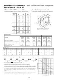
The following table shows the relationship of the starting torque to the rated torque.<br />
Single-phase motor<br />
3-phase motor<br />
2pole 0.60 x M rated 1.2 x M rated<br />
4pole 0.70 x M rated 1.3 x M rated<br />
8pole 0.85 x M rated 1.6 x M rated<br />
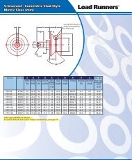
The typical torque characteristics can be seen in Fig. 1 and 2.<br />
The efficiency of these precision motors are as follows<br />
Single-phase motor<br />
3-phase motor<br />
2pole up to 63 % up to 72 %<br />
4pole up to 52 % up to 56 %<br />
8pole up to 29 % up to 35 %<br />
The resulting rated speeds for both types are then:<br />
You have the following benefits when<br />
using Neckar-Induction motors:<br />
With 3-phase current motors simple<br />
connection to the 3-phase supply.<br />
With capacitance motors simple connection<br />
to the lighting circuit.<br />
High specific power volume.<br />
2pole 2600–2750 min –1<br />
4pole 1200–1300 min –1<br />
8pole 600– 650 min –1<br />
Rotation reversal by simply changing the<br />
poles.<br />
Extremely long service life only dependent<br />
on ball bearings.<br />
Because of our modular design all motors<br />
can be combined with various gears<br />
detectors, brakes etc.<br />
Extremely quite running in all load<br />
phases.<br />
you, too, will find your made-to-measure<br />
drive<br />
Md=Ncm<br />
K 662<br />
Md=Ncm<br />
K 662<br />
M stall<br />
M start<br />
M stall<br />
M start<br />
M rated<br />
Rated operation c=2.5 µF<br />
Rated operation λ<br />
Rated operation ∆ c=3 µF<br />
M rated<br />
M start<br />
Figure 1 Figure 2<br />
For data sheets see page 27–38<br />
18 ■
MOTOREN<br />
NECKAR<br />
Technology<br />
Switchable Induction <strong>Motors</strong><br />
Advantages:<br />
Switchable motors for 230 or 400 V<br />
or single-phase or 3-phase alternating<br />
currents.<br />
The idea for these motors came from<br />
modern production technology with the<br />
demand for minimum stock keeping.<br />
The latter is reduced to a minimum as it<br />
covers three types of operation.<br />
Simple connection to lighting or 3-phase<br />
current supply.<br />
Switchable voltage 230/400 V.<br />
Very reliable operation.<br />
High specific power volume.<br />
Very quite running in all load phases.<br />
Extremely long service life and maintenance-free,<br />
as there are no wearing<br />
commutators.<br />
Rotation reversal by replacement of two<br />
wires (3~) or pole reversal (2~)<br />
Can be combined with various gears,<br />
shaft encoders and controls so that customer<br />
specific designs can be easily<br />
made.<br />
Properties:<br />
The motors of series KD are 3-phase<br />
current motors with a free neutral point<br />
and designed for 400 Volt. They are<br />
equipped with terminal boxes as a standard<br />
and allow the following types of<br />
operation to be selected:<br />
1. 3-phase operation 400 V with star connection<br />
2. 3-phase 230 V with delta connection<br />
Note: suitable for variable-frequency<br />
inverter operation in this arrangement.<br />
3. Single-phase operation 230 V Delta<br />
connection according to Steinmetz<br />
The design of the motors corresponds to<br />
series K, D and R.<br />
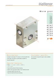
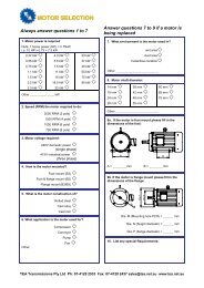
M start<br />
M start<br />
Md=Ncm<br />
Rated operation<br />
KD 662<br />
Rated operation λ c=3 µF<br />
The efficiency of these precision motors in<br />
single-phase operation is:<br />
2 pole design up to 63 %<br />
4 pole design up to 52 %<br />
for 3-phase operation:<br />
2 pole design up to 72 %<br />
4 pole design up to 56 %<br />
It exhibits the characteristic of its category<br />
both as a 3-phase current motor and as a<br />
single-phase motor. However this voltage<br />
category is only possible for the sizes 6<br />
and 8.<br />
Design<br />
Stator with multi-slotted winding, shortcircuit<br />
rotor. Aluminium round housing<br />
closed on all sides, which makes higher<br />
protection types possible (up to IP 65<br />
among others).<br />
Designed for continuous duty S1, higher<br />
powers in short-time duty. Rolling bearing<br />
with lifetime lubrication.<br />
M stall<br />
M rated<br />
Connection<br />
K 4, IP 44, PG 11 (see Page 13)<br />
Switches:<br />
400 V 3~ Y<br />
230 V 3~ ∆<br />
230 V 1~ ∆<br />
Capacitor<br />
A capacitor is necessary for single-phase<br />
operation. See page 98 for options.<br />
Scope of delivery<br />
1 blind plug, 1 cable screw connection.<br />
All series KD motors can be supplied with<br />
cooling fin housing and increased continuous<br />
power. There is also the possibility of<br />
base mounting.<br />
Please enquire.<br />
<strong>Motors</strong><br />
For data sheets see page 25–26<br />
■ 19
MOTOREN<br />
NECKAR<br />
Technology<br />
Synchronous <strong>Motors</strong><br />
Advantages:<br />
Used for all drives where a time dependent<br />
speed is required.<br />
Simple connection to the lighting circuit.<br />
Very reliable during operation.<br />
Extremely long service life and maintenance-free,<br />
as there are no wearing<br />
commutators.<br />
Can be combined with various gears,<br />
shaft encoders and controls so that customer<br />
specific designs can be easily<br />
made.<br />
Properties:<br />
We differentiate between two type of synchronous<br />
motors:<br />
Type 1: Hybrid motors with a two part rotor.<br />
One part consists of a conventional<br />
squirrel-cage rotor as found in every 3-<br />
phase motor. Its function is to simply accelerate<br />
the complete rotor from standstill to<br />
the synchronous speed.<br />
On reaching the synchronous speed the<br />
second part of the rotor “ties on” with the<br />
rotating stator field and a powerful rareearth<br />
magnet produces the required constant<br />
speed. The design of the synchronous<br />
motors corresponds to the series K and D.<br />
The speed is coupled to the mains frequency.<br />
Depending on the design of the winding,<br />
2 or 4 pole – the following rated<br />
speeds are attained at 50 Hz<br />
2 pole motors approx.<br />
3000 min –1 (60 Hz x 1.2)<br />
4pole 1500 min –1<br />
The efficiency of these precision<br />
motors is<br />
approx. 35 % for 2 pole motors<br />
approx. 22 % for 4 pole motors.<br />
For all motors there is a pole-phase relationship.<br />
For these motors care must be<br />
taken to keep the revolving mass to be<br />
driven to a minimum as otherwise the<br />
“pulling-in synchronism” is not guaranteed.<br />
At high speed a step is formed between<br />
the asynchronous and synchronous speed<br />
which, with a high inertia of masses, cannot<br />
be overcome.<br />
Speed control for synchronous motors is<br />
only possible via the frequency. Exact<br />
knowledge about the drive in question in<br />
all of its phases is required for the design<br />
of such drives.<br />
Type 2: These motors are built with a reluctance<br />
rotor.<br />
Synchronous motors are delivered as<br />
various types and number of poles with<br />
various operating voltages.<br />
Please ask our sales department for a<br />
suitable solution for your drive problem.<br />
20 ■
MOTOREN<br />
NECKAR<br />
Technology<br />
Direct current <strong>Motors</strong><br />
Properties:<br />
The series G direct current motors<br />
are characterised by high power<br />
and small construction volume. The<br />
field is produced with the aid of<br />
permanent magnets; and the motor<br />
therefore exhibits shunt characteristics<br />
and has favourable efficiency<br />
as there is no need for electromagnetic<br />
field excitation.<br />
The commutator is normally 12-<br />
part, also 24-part for special demands.<br />
The normal speeds are held relatively<br />
low in order to ensure a<br />
longer service life and a favourable<br />
sound pressure level, especially<br />
in combination with gears.<br />
The service life of the brushes is<br />
approx. 5,000 hours. They are especially<br />
responsible for the quality<br />
of the direct current operational<br />
conditions. The speed behaves linearly<br />
to the applied voltage. Power<br />
which is not taken up expresses itself<br />
by an increase in speed, also<br />
with direct current motors. The starting<br />
torque is several times greater<br />
than the rated torque. Because of<br />
this characteristic a direct current<br />
motor is also suitable for difficult<br />
starting. The data for the direct current<br />
are designed for an upper<br />
threshold portion of max. 4.2 %.<br />
For operation on a voltage source<br />
which is “not ideal”, the rated<br />
power P 2 must be reduced to the<br />
following values:<br />
– Single phase bridge rectifier<br />
0.7 – 0.8 x P 2<br />
– Single-phase half-wave rectifier<br />
0.5 – 0.6 x P 2<br />
– Thyristor controls<br />
0.5 – 0.6 x P 2<br />
G 525 G 645<br />
G 545 G 665<br />
G 565 G 865<br />
<strong>Motors</strong><br />
Design<br />
Compact design motor, 12-part<br />
commutator, carefully adjusted<br />
commutation, brushes lying inwards.<br />
Round housing closed on<br />
all sides, which makes higher protection<br />
types possible (up to IP 65<br />
among others). Designed for continuous<br />
duty S1, higher power in<br />
short-time duty.<br />
G 665 S<br />
G 865 S<br />
■ 21
MOTOREN<br />
NECKAR<br />
Technology<br />
Brushless Direct current <strong>Motors</strong><br />
The series M and MH electronically commutated<br />
direct current motors are of similar<br />
construction to induction motors. The 12-<br />
slot stator is equipped with a 4-pole winding.<br />
Adjustment of the winding to the voltage<br />
and operating conditions is possible.<br />
In comparison to the induction motor a rotor<br />
is used here with high-quality Neodymium<br />
magnets instead of the “simple” squirrel-cage.<br />
Rotor position detection is integrated in the<br />
motor. This consists of a magnetic disk rotating<br />
with the rotor and three Hall sensors<br />
arranged at 120°.<br />
The signals from the rotor position detection<br />
are evaluated by the control electronics<br />
required for operation. According to<br />
the position of the rotor the winding<br />
strands are streamed according to the following<br />
control scheme.<br />
Properties:<br />
The series M electronically commutated<br />
direct current motors are characterised by<br />
extreme reversing and acceleration properties.<br />
Series M is to some degree<br />
replaceable with other current types of<br />
similar size.<br />
While the service life of mechanically<br />
commutated direct current motors depends<br />
on that of the brushes, lying at approx.<br />
3,000–5,000 hours, the service life of an<br />
electronically commutated direct current<br />
motor only depends on the service life expectancy<br />
of the ball bearings, lying at<br />
over 20,000, presuming professional installation.<br />
The electronically commutated<br />
motor combines the known advantages of<br />
the 3-phase motor and the special features<br />
of the MH-motor in an almost exemplary<br />
fashion.<br />
The connection between speed, number of poles and number of slots on the stator can<br />
be seen in the following table.<br />
Rated speed No. of poles No. of slots<br />
3000 min –1 4 12<br />
750 min –1 8 24<br />
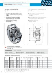
Standard control scheme<br />
left-hand rotation right-hand rotation<br />
Control scheme<br />
1 Revolution<br />
Besonderheiten des MH-<strong>Motors</strong><br />
As already mentiones, external control<br />
electronics are required for operation of<br />
the M-motors. With the development of<br />
integrated electronics we have been able<br />
to integrate a complete 1-Q-Controller into<br />
the motor. A lot of new ideas had to be<br />
used for this. The advantages of this solution<br />
are numerous:<br />
Sensor 1<br />
Sensor 2<br />
Sensor 3<br />
Commutation<br />
phase<br />
Motor phase A<br />
Motor phase B<br />
Motor phase C<br />
Motor phase A<br />
Motor phase B<br />
Motor phase C<br />
– The sensitive rotor position detection<br />
leads do not have to be led out anymore.<br />
– Damage caused by rotor position detector<br />
wiring faults can not occur.<br />
– The control of complex machines is<br />
simplified.<br />
– Continuous power as with motors with<br />
external electronics<br />
– Control range 30:1<br />
– Rotation reversal, fault signal output,<br />
impulse output (all SPS (Stored programme<br />
controller) level), short circuit<br />
braking and smooth starting with terminal<br />
box K4 integrated as standard.<br />
– Optional plug-and-socket connection.<br />
– “Stand-Alone-Operation“ possible.<br />
22 ■
MOTOREN<br />
Technology<br />
Characteristics<br />
NECKAR<br />
M 313 M 563 MH 333<br />
<strong>Motors</strong><br />
M 333 M 663 MH 543<br />
M 363 M 863 MH 563<br />
M 543 MH 313 MH 663<br />
■ 23
MOTOREN<br />
NECKAR<br />
Electronically commutated<br />
MH 5...8 with integrated 1Q-Controller<br />
Terminal lead designation with terminal box K4 standard:<br />
External wiring<br />
*1 Rotating right<br />
*2 Brake active<br />
*3 No release<br />
Attention!<br />
Maximum connection voltage 26,5 V!<br />
Coded switch positions for internal operation:<br />
J1 Rotation direction: ON = Rotating left<br />
J2 Brake:<br />
ON = Short circuit brake inactive<br />
J3 Release:<br />
ON = Motor released<br />
J4 Int./Ext.-Set-point: ON = Internal set-point assignment<br />
J5 Ramp:<br />
ON = Set-point ramp inactive<br />
For external function selection plug corresponding<br />
bridges on the following positions –<br />
otherwise danger of short circuit!<br />
J1 Rotation direction:<br />
J2 Brake:<br />
J3 Release:<br />
J4 Int./ext. Set-point:<br />
OFF – Position<br />
OFF – Position<br />
OFF – Position<br />
OFF – Position = External set-point<br />
OFF – Position = assignment<br />
+VC: 24VDC +10/– 6 %<br />
Gnd: Supply earth<br />
Rev: Rotation reversal (High level 12..24V = Rotating left)<br />
Brake: Short circuit brake (High level 12..24V = Brake inactive)<br />
Enab.: Motor release (High level 12..24V = Function)<br />
S +: Set-point + (12V)<br />
S: Set-point input (0..10V)<br />
S –: Set-point earth<br />
Erro: Fault signal output (Open collector max. 45V 300mW)<br />
RI-A: Impulse output A-Spur (Open collector max. 45V 300mW) 2 Impulse/min –1<br />
RI-B: Impulse output B-Spur (Open collector max. 45V 300mW) 2 Impulse/min –1 120° Phase displacement<br />
D1: Ready for operation indicator<br />
D2: Fault / Excess current indicator<br />
Control range 30:1<br />
Speed range 100 – 3000 min –1<br />
Note:<br />
– The respective functions or operating elements should be reserved either only externally or internally as otherwise this can result<br />
in incorrect functions.<br />
– For internal set-point assignment the trimmer P2 is used for adjusting the speed.<br />
– For external set-point assignment the trimmer P2 is used for adjusting the maximum speed (set-point adjustment).<br />
– Trimmer P1 with an active ramp is used for adjusting the starting time.<br />
24 ■
MOTOREN<br />
NECKAR<br />
Switchable Induction <strong>Motors</strong><br />
Series KD, Size 6 68 mm<br />
Properties:<br />
Induction principle: speed is dependent<br />
on load and supply frequency. Variable<br />
speeds possible with converters,<br />
see information Series D<br />
Simple connection to lighting circuit<br />
(230 V, 50 Hz)<br />
or 3-phase circuit 3 x 400 V AC<br />
K4 Terminal boxes<br />
Long service life<br />
Protection type IP 44 Standard<br />
Options:<br />
Thermal protection: recommended option<br />
for unusual demands to protect the winding.<br />
Special protection type: up to IP 65 problem<br />
free and cost-effective.<br />
Special voltages: can be supplied.<br />
Housing design: choice of housing design<br />
with cooling fins for special applications,<br />
which has better cooling properties compared<br />
to the standard smooth surface,<br />
allowing higher rated powers to be<br />
achieved.<br />
<strong>Motors</strong><br />
Ambient temperature max. 40° C<br />
Rated Operating Rated Starting Rated Rated Housing Weight Moment Operating<br />
speed voltage current torque torque power length of capacitor<br />
(load Effective (Continuous (without inertia<br />
Motor type dependent) value 50 Hz duty S1) shaft)<br />
N rated U I rated M start M rated P 2 L G J C<br />
min 1 V mA Ncm Ncm W mm kg gcm 2 µF<br />
KD 622 1∼ 2650 230 140 2.6 4.2 11.4 72 0.85 210 2.5<br />
KD 622 3 ∼ 2650 400 55 9.1 5.2 14.2 72 0.85 210<br />
KD 642 1 ∼ 2650 230 152 2.4 7.0 19.5 92 1.20 390 2.5<br />
KD 642 3 ∼ 2650 400 70 12.0 8.7 23.8 92 1.20 390<br />
KD 662 1 ∼ 2650 230 290 3.5 12.5 34.0 112 1.70 595 3.0<br />
KD 662 3 ∼ 2650 400 110 25.0 15.4 42.0 112 1.70 595<br />
KD 644 1 ∼ 1250 230 150 4.5 9.1 12.0 92 1.20 390 2.5<br />
KD 644 3 ∼ 1250 400 60 14.7 10.1 13.0 92 1.20 390<br />
KD 664 1 ∼ 1250 230 185 7.3 9.4 12.8 112 1.70 595 3.0<br />
KD 664 3 ∼ 1250 400 65 21.0 11.7 16.0 112 1.70 595<br />
Accessories<br />
Type Description Page<br />
Brake B 3/B 77 20/80 Ncm 54<br />
<strong>Inc</strong>remental RE 6 up to 100 imp./rev 87<br />
shaft encoder RI 6 up to 2500 imp./rev 85<br />
RV up to 500 imp./rev 86<br />
Tachometer T 2, T 3 89<br />
Capacitor 98<br />
Gears-Recommendations<br />
Design Type Mmax Page<br />
Spur Z 6 2.5–7.0 Nm 60<br />
Z 67/M 67 0.35–4.0 Nm 62/68<br />
M 7 2.5–7.0 Nm 65<br />
Worm S 567 1.5–3.2 Nm 76<br />
S 668 5.4–8.4 Nm 77<br />
Planetary P 60 8.0–50 Nm 71<br />
■ 25
MOTOREN<br />
NECKAR<br />
Switchable Induction <strong>Motors</strong><br />
Series KD, Size 8 83 mm<br />
Properties:<br />
Induction principle: speed is dependent<br />
on load and supply frequency. Variable<br />
speeds possible with converters,<br />
see information Series D<br />
Simple connection to lighting circuit<br />
(230 V, 50 Hz)<br />
or 3-phase circuit 3 x 400 V AC<br />
K4 Terminal boxes<br />
Long service life<br />
Protection type IP 44 Standard<br />
Options:<br />
Thermal protection: recommended option<br />
for unusual demands to protect the winding.<br />
Special protection type: up to IP 65 problem<br />
free and cost-effective.<br />
Special voltages: can be supplied.<br />
Housing design: choice of housing design<br />
with cooling fins for special applications,<br />
which has better cooling properties compared<br />
to the standard smooth surface,<br />
allowing higher rated powers to be<br />
achieved.<br />
Ambient temperature max. 40° C<br />
Rated Operating Rated Starting Rated Rated Housing Weight Moment Operating<br />
speed voltage current torque torque power length of capacitor<br />
(load Effective (Continuous (without inertia<br />
Motor type dependent) value 50 Hz duty S1) shaft)<br />
N rated U I rated M start M rated P 2 L G J C<br />
min 1 V mA Ncm Ncm W mm kg gcm 2 µF<br />
KD 822 1∼ 2700 230 215 6.0 6.3 17.0 72 1.45 375 4.0<br />
KD 822 3 ∼ 2700 400 88 25.9 9.3 25.0 72 1.45 375<br />
KD 842 1 ∼ 2700 230 250 7.0 12.7 34.0 92 1.90 750 4.0<br />
KD 842 3 ∼ 2700 400 190 47.0 13.0 35.0 92 1.90 750<br />
KD 862 1 ∼ 2700 230 310 14.0 16.0 44.0 112 2.50 1050 5.0<br />
KD 862 3 ∼ 2700 400 145 61.0 15.0 44.0 112 2.50 1050<br />
KD 824 1 ∼ 1300 230 155 6.0 8.2 11.2 72 1.45 375 2.5<br />
KD 824 3 ∼ 1300 400 70 14.0 8.9 12.2 72 1.45 375<br />
KD 844 1 ∼ 1300 230 230 14.0 13.0 17.6 92 1.90 750 3.0<br />
KD 844 3 ∼ 1300 400 135 43.0 12.0 17.6 92 1.90 750<br />
KD 864 1 ∼ 1300 230 300 9.5 26.0 35.0 112 2.50 1050 3.5<br />
KD 864 3 ∼ 1300 400 155 47.0 31.0 42.8 112 2.50 1050<br />
Accessories<br />
Type Description Page<br />
Brake B 3/B 77 20/80 Ncm 54<br />
<strong>Inc</strong>remental RE 8 up to 100 imp./rev 87<br />
shaft encoder RI 8 up to 2500 imp./rev 85<br />
RV up to 500 imp./rev 86<br />
Tachometer T 2, T 3 89<br />
Capacitor 98<br />
26 ■<br />
Gears-Recommendations<br />
Design Type Mmax Page<br />
Spur Z 8, M 8 3.0–12 Nm 61/66<br />
M 10 10–30 Nm 67<br />
M 189 2.5–18 Nm 69<br />
Worm S 668 5.4–8.4 Nm 77<br />
S 769 11–15 Nm 78<br />
Planetary PE 8 20–80 Nm 74<br />
P 60 8.0–50 Nm 74
MOTOREN<br />
Series K, Size 3 36 mm<br />
NECKAR<br />
Single-phase Capacitance <strong>Motors</strong><br />
Properties:<br />
Induction principle: speed is dependent<br />
on load and supply frequency. Variable<br />
speeds possible with converters,<br />
see information Series D<br />
Simple connection to lighting circuit<br />
(230 V, 50 Hz or via 24 V transformer)<br />
Loose stranded wires<br />
Protection type IP 40 Standard<br />
Long service life<br />
Options:<br />
Thermal protection: recommended option<br />
for unusual demands to protect the winding.<br />
Special voltages: can be supplied.<br />
Housing design: choice of housing design<br />
with cooling fins for special applications,<br />
which has better cooling properties compared<br />
to the standard smooth surface, allowing<br />
higher rated powers to be<br />
achieved.<br />
Type of operation: special design for shorttime<br />
duty (Series KV) with higher power<br />
available (see Page 32).<br />
<strong>Motors</strong><br />
Ambient temperature max. 40° C<br />
Rated Operating Rated Starting Rated Power Rated Housing Weight Moment Operating<br />
speed voltage current torque torque input power length of capacitor<br />
(load Effective (Continuous (without inertia<br />
Motor type dependent) value 50 Hz duty S1) shaft)<br />
N rated U I rated M start M rated P 1 P 2 L G J C<br />
min 1 V mA Ncm Ncm W W mm kg gcm 2 µF<br />
K 312 2600 24 250 0.7 0.25 3.6 0.75 46 0.1 7.2 30.0<br />
K 332 2600 24 370 1.1 0.6 5.3 1.9 66 0.25 16.0 40.0<br />
K 362 2600 230 75 1.8 1.6 13.2 3.2 91 0.4 27.0 1.2<br />
K 314 1200 24 280 0.2 0.15 4.0 0.2 46 0.1 7.2 20.0<br />
K 334 1200 24 280 0.6 0.2 4.0 0.26 66 0.25 16.0 40.0<br />
K 364 1200 230 65 0.8 1.0 9.3 1.4 91 0.4 27.0 1.5<br />
Accessories<br />
Type Description Page<br />
Capacitor 98<br />
Accessories such as shaft encoders, brakes etc. are optional and can<br />
be supplied after discussion with the Technical Service department.<br />
Gears-Recommendations<br />
Design Type Mmax Page<br />
Spur Z 3 0.5–1.2 Nm 58<br />
Worm S 345 1.4–2 Nm 75<br />
Planetary PE 3 2.0–15 Nm 72<br />
P 30 0.75–4.5 Nm 70<br />
■ 27
MOTOREN<br />
NECKAR<br />
Single-phase Capacitance <strong>Motors</strong> Series K<br />
Series K, Size 5 53 mm<br />
Properties:<br />
Induction principle: speed is dependent<br />
on load and supply frequency. Variable<br />
speeds possible with converters,<br />
see information Series D<br />
Simple connection to lighting circuit<br />
(230 V, 50 Hz)<br />
Loose stranded wires<br />
Protection type IP 40 Standard<br />
Long service life<br />
Options:<br />
Thermal protection: recommended option<br />
for unusual demands to protect the winding.<br />
Special protection type: up to IP 65 problem<br />
free and cost-effective.<br />
Special voltages: can be supplied.<br />
Type of operation: special design for shorttime<br />
duty with higher power available.<br />
Ambient temperature max. 40° C<br />
Rated Operating Rated Starting Rated Power Rated Housing Weight Moment Operating<br />
speed voltage current torque torque input power length of capacitor<br />
(load Effective (Continuous (without inertia<br />
Motor type dependent) value 50 Hz duty S1) shaft)<br />
N rated U I rated M start M rated P 1 P 2 L G J C<br />
min 1 V mA Ncm Ncm W W mm kg gcm 2 µF<br />
K 522 2600 230 62 1.2 1.2 13.6 3.2 72 0.47 67.5 1.0<br />
K 542 2600 230 146 2.6 3.5 29.2 10.0 92 0.72 128.0 1.5<br />
K 562 2600 230 110 2.6 4.8 25.0 11.8 112 1.0 200.0 1.5<br />
K 524 1200 230 46 0.8 1.0 10.2 1.23 72 0.47 67.5 1.0<br />
K 544 1200 230 65 1.7 2.4 14.7 3.23 92 0.72 128.0 1.0<br />
K 564 1200 230 100 3.4 3.8 22.2 4.80 112 1.0 200.0 1.5<br />
Accessories<br />
Type Description Page<br />
Brake B 35 8 Ncm 54<br />
<strong>Inc</strong>remental RE 5 up to 100 imp./rev 87<br />
shaft encoder RI 5 up to 1500 imp./rev 85<br />
RV up to 500 imp./rev 86<br />
Tachometer T 3 89<br />
Capacitor 98<br />
Gears-Recommendations<br />
Design Type Mmax Page<br />
Spur Z 5 1.0–3.3 Nm 59<br />
Z 67/M 67 0.35–4 Nm 62/68<br />
Worm S 567 1.5–3.2 Nm 76<br />
Planetary PE 3 2.0–15 Nm 72<br />
PE 5 6.0–20 Nm 73<br />
28 ■
MOTOREN<br />
Series K, Size 6 68 mm<br />
NECKAR<br />
Single-phase Capacitance <strong>Motors</strong> Series K<br />
Properties:<br />
Induction principle: speed is dependent<br />
on load and supply frequency. Variable<br />
speeds possible with converters,<br />
see information Series D<br />
Simple connection to lighting circuit<br />
(230 V, 50 Hz)<br />
Plug connection standard<br />
Long service life<br />
Protection type IP 44 Standard<br />
Options:<br />
Thermal protection: recommended option<br />
for unusual demands to protect the winding.<br />
Special protection type: up to IP 65 problem<br />
free and cost-effective.<br />
Special voltages: can be supplied.<br />
Housing design: choice of housing design<br />
with cooling fins for special applications,<br />
which has better cooling properties compared<br />
to the standard smooth surface,<br />
allowing higher rated powers to be<br />
achieved.<br />
Type of operation: special design for shorttime<br />
duty with higher power available.<br />
<strong>Motors</strong><br />
Ambient temperature max. 40° C<br />
Rated Operating Rated Starting Rated Power Rated Housing Weight Moment Operating<br />
speed voltage current torque torque input power length of capacitor<br />
(load Effective (Continuous (without inertia<br />
Motor type dependent) value 50 Hz duty S1) shaft)<br />
N rated U I rated M start M rated P 1 P 2 L G J C<br />
min 1 V mA Ncm Ncm W W mm kg gcm 2 µF<br />
K 622 2650 230 107 2.8 4.0 24.5 10.5 72 0.85 210 1.5<br />
K 642 2650 230 164 4.0 7.0 37.0 18.7 92 1.20 390 2.0<br />
K 662 2650 230 232 6.1 8.0 45.0 22.0 112 1.70 595 2.5<br />
K 624 1250 230 91 2.6 3.5 20.0 4.5 72 0.85 210 1.5<br />
K 644 1250 230 150 5.6 7.2 28.0 10.0 92 1.20 390 1.5<br />
K 664 1250 230 170 9.0 10.0 28.5 13.0 112 1.70 595 2.0<br />
Accessories<br />
Type Description Page<br />
Brake B 3/B 77 20/80 Ncm 54<br />
<strong>Inc</strong>remental RE 6 up to 100 imp./rev 87<br />
shaft encoder RI 6 up to 2500 imp./rev 85<br />
RV up to 500 imp./rev 86<br />
Tachometer T 1 89<br />
Capacitor 98<br />
Gears-Recommendations<br />
Design Type Mmax Page<br />
Spur Z 6 2.5–7.0 Nm 60<br />
Z 67/M 67 0.35–4.0 Nm 62/68<br />
M 7 2.5–7.0 Nm 65<br />
Worm S 567 1.5–3.2 Nm 76<br />
S 668 5.4–8.4 Nm 77<br />
Planetary P 60 8.0–50 Nm 71<br />
■ 29
MOTOREN<br />
NECKAR<br />
Single-phase Capacitance <strong>Motors</strong><br />
Series K, Size 8 83 mm<br />
Properties:<br />
Induction principle: speed is dependent<br />
on load and supply frequency. Variable<br />
speeds possible with converters,<br />
see information Series D<br />
Simple connection to lighting circuit<br />
(230 V, 50 Hz)<br />
Plug connection standard<br />
Long service life<br />
Protection type IP 44 Standard<br />
Options:<br />
Thermal protection: recommended option<br />
for unusual demands to protect the winding.<br />
Special protection type: up to IP 65 problem<br />
free and cost-effective.<br />
Special voltages: can be supplied.<br />
Housing design: choice of housing design<br />
with cooling fins for special applications,<br />
which has better cooling properties compared<br />
to the standard smooth surface,<br />
allowing higher rated powers to be<br />
achieved.<br />
Type of operation: special design for shorttime<br />
duty with higher power available<br />
(see Page 33)<br />
d2 = 8f6 mm; at K 882 and 884 10f6 mm<br />
Ambient temperature max. 40° C<br />
Rated Operating Rated Starting Rated Power Rated Housing Weight Moment Operating<br />
speed voltage current torque torque input power length of capacitor<br />
(load Effective (Continuous (without inertia<br />
Motor type dependent) value 50 Hz duty S1) shaft)<br />
N rated U I rated M start M rated P 1 P 2 L G J C<br />
min 1 V mA Ncm Ncm W W mm kg gcm 2 µF<br />
K 822 2700 230 200 5.6 9.5 45 24 72 1.45 375 2.5<br />
K 842 2700 230 243 6.4 12.0 52 32 92 1.90 750 3.0<br />
K 862 2700 230 390 10.4 17.0 90 47 112 2.50 1050 4.5<br />
K 882 2700 230 605 15.0 27.5 126 80 132 3.35 1400 8.0<br />
K 824 1300 230 140 5.2 8.0 31.0 10.5 72 1.45 375 2.0<br />
K 844 1300 230 192 11.7 13.0 39.0 17.5 92 1.90 750 2.5<br />
K 864 1300 230 250 13.5 17.0 52.0 21.0 112 2.50 1050 3.0<br />
K 884 1300 230 400 18.0 30.0 87.0 41.0 132 3.35 1400 5.0<br />
K 828 650 230 107 4.5 5.3 23.5 3.4 72 31.45 450 1.5<br />
K 848 650 230 171 10.0 11.4 36.0 7.8 92 51.90 900 2.0<br />
K 868 650 230 210 17.0 20.0 45.0 13.1 112 2.50 1260 3.0<br />
Accessories<br />
Type Description Page<br />
Brake B 3/B 77 20/80 Ncm 54<br />
<strong>Inc</strong>remental RE 8 up to 100 imp./rev 87<br />
shaft encoder RI 8 up to 2500 imp./rev 85<br />
RV up to 500 imp./rev 86<br />
Tachometer T 1, T 3 89<br />
Capacitor 98<br />
30 ■<br />
Gears-Recommendations<br />
Design Type Mmax Page<br />
Spur Z 8, M 8 3.0–12 Nm 61/66<br />
M 10 10–30 Nm 67<br />
M 189 2.5–18 Nm 69<br />
Worm S 668 5.4–8.4 Nm 77<br />
S 769 11–15 Nm 78<br />
Planetary PE 8 20–80 Nm 74<br />
P 60 8.0–50 Nm 71
MOTOREN<br />
New!<br />
Series K, Size 95 95 mm<br />
NECKAR<br />
Single-phase Capacitance <strong>Motors</strong><br />
Properties:<br />
Induction principle: speed is dependent<br />
on load and supply frequency. Variable<br />
speeds possible with converters,<br />
see information Series D<br />
Long service life<br />
Protection type IP 44 Standard<br />
Insulation class F<br />
Options:<br />
Thermal protection: recommended option<br />
for unusual demands to protect the<br />
winding.<br />
Special protection type: up to IP 65 problem<br />
free and cost-effective.<br />
Special voltages: can be supplied.<br />
Type of operation: special design for shorttime<br />
duty with higher power available.<br />
<strong>Motors</strong><br />
Ambient temperature max. 40° C<br />
Rated Operating Rated Starting Rated Power Rated Housing Weight Moment Operating<br />
speed voltage current torque torque input power length of capacitor<br />
(load Effective (Continuous (without inertia<br />
Motor type dependent) value 50 Hz duty S1) shaft)<br />
N rated U I rated M start M rated P 1 P 2 L G J C<br />
min 1 V mA Ncm Ncm W W mm kg gcm 2 µF<br />
K 9562 2730 230 952 22.5 32 139 91 140 3.7 1532 9.0<br />
K 9582 2730 230 1250 28 50 211 143 160 4.5 1964 12.0<br />
K 9564 1320 230 660 27 36 96 50 140 3.7 1532 6.0<br />
K 9584 1320 230 851 32 55 134 76 160 4.5 1964 8.0<br />
Accessories<br />
Type Description Page<br />
Brake B 3/B 77 20/80 Ncm 54<br />
<strong>Inc</strong>remental RE 8 up to 100 imp./rev 87<br />
shaft encoder RI 8 up to 2500 imp./rev 85<br />
RV up to 500 imp./rev 86<br />
Tachometer T 1, T 3 89<br />
Capacitor 98<br />
Gears-Recommendations<br />
Design Type Mmax Page<br />
Spur Z 8, M 8 3.0–12 Nm 61/66<br />
M 10 10–30 Nm 67<br />
M 189 2.5–18 Nm 69<br />
Worm S 769 11–15 Nm 78<br />
Planetary PE 8 20–80 Nm 74<br />
P 60 8.0–50 Nm 71<br />
■ 31
MOTOREN<br />
NECKAR<br />
Single-phase Capacitance <strong>Motors</strong><br />
Size 3 36 mm, for short-time duty S 2<br />
Properties:<br />
Induction principle: speed is dependent<br />
on load and supply frequency. Variable<br />
speeds possible with converters,<br />
see information Series D<br />
Simple connection to lighting circuit<br />
(230 V, 50 Hz)<br />
Loose stranded wires<br />
Long service life<br />
Protection type IP 40 Standard<br />
Options:<br />
Thermal protection: recommended option<br />
for unusual demands to protect the<br />
winding.<br />
Special voltages: can be supplied.<br />
Housing design: choice of housing design<br />
with cooling fins for special applications,<br />
which has better cooling properties compared<br />
to the standard smooth surface,<br />
allowing higher rated powers to be<br />
achieved.<br />
Ambient temperature max. 40° C<br />
On-period: S2 3 min.<br />
Rated Operating Rated Starting Rated Power Rated Housing Weight Moment Operating<br />
speed voltage current torque torque input power length of capacitor<br />
(load Effective (Continuous (without inertia<br />
Motor type dependent) value 50 Hz duty S1) shaft)<br />
N rated U I rated M start M rated P 1 P 2 L G J C<br />
min 1 V mA Ncm Ncm W W mm kg gcm 2 µF<br />
KV 332 2200 230 200 2.3 1.8 44.4 4.1 66 0.20 16 1.5<br />
KV 362 2500 230 350 4.6 2.9 79.2 7.6 91 0.40 27 3.0<br />
Accessories<br />
Type Description Page<br />
Capacitor 98<br />
Gears-Recommendations<br />
Design Type Mmax Page<br />
Spur Z 3 0.5–1.2 Nm 58<br />
Worm S 345 1.4–2 Nm 75<br />
Planetary PE 3 2.0–15 Nm 72<br />
P 30 0.75–4.5 Nm 70<br />
32 ■
MOTOREN<br />
NECKAR<br />
Single-phase Capacitance <strong>Motors</strong><br />
Size 8 83 mm, for short-time duty S 2<br />
Properties:<br />
Induction principle: speed is dependent<br />
on load and supply frequency. Variable<br />
speeds possible with converters,<br />
see information Series D<br />
Simple connection to lighting circuit<br />
(230 V, 50 Hz)<br />
Plug connector standard<br />
Long service life<br />
Protection type IP 44 Standard<br />
Options:<br />
Thermal protection: recommended option<br />
for unusual demands to protect the winding.<br />
Special protection type: up to IP 65 problem<br />
free and cost-effective.<br />
Special voltages: can be supplied.<br />
Housing design: choice of housing design<br />
with cooling fins for special applications,<br />
which has better cooling properties compared<br />
to the standard smooth surface,<br />
allowing higher rated powers to be<br />
achieved.<br />
<strong>Motors</strong><br />
Ambient temperature max. 40° C<br />
On-period: Type KV S2 6 min., Type KVa S2 4.5 min.<br />
Rated Operating Rated Starting Rated Power Rated Housing Weight Moment Operating<br />
speed voltage current torque torque input power length of capacitor<br />
(load Effective (Continuous (without inertia<br />
Motor type dependent) value 50 Hz duty S1) shaft)<br />
N rated U I rated M start M rated P 1 P 2 L G J C<br />
min 1 V mA Ncm Ncm W W mm kg gcm 2 µF<br />
KV 844 1250 230 650 40 30 165 40 92 2.5 750 10<br />
KV 842 2200 230 710 20 42 156 97 92 2.5 750 10<br />
KV 842 2200 230 750 30 42 165 97 92 2.5 750 14<br />
KVa 842 2200 230 1800 50 52 320 120 92 2.5 750 20<br />
Accessories<br />
Type Description Page<br />
Brake B 3/B 77 20/80 Ncm 54<br />
<strong>Inc</strong>remental RE 8 up to 100 imp./rev 87<br />
shaft encoder RI 8 up to 2500 imp./rev 85<br />
R V up to 500 imp./rev 86<br />
Tachometer T 1, T 3 89<br />
Capacitor 98<br />
Gears-Recommendations<br />
Design Type Mmax Page<br />
Spur Z 8, M 8 3.0–12 Nm 61/66<br />
M 10 10–30 Nm 67<br />
M 189 2.5–18 Nm 69<br />
Worm S 668 5.4–8.4 Nm 77<br />
S 769 11–15 Nm 78<br />
Planetary PE 8 20–80 Nm 74<br />
P 60 8.0–50 Nm 71<br />
■ 33<br />
■ 33
MOTOREN<br />
New!<br />
Boosted Induction <strong>Motors</strong><br />
Boosted 4-pole Series<br />
NECKAR<br />
Properties:<br />
Induction principle: speed is dependent<br />
on load and supply frequency. Variable<br />
speeds possible with converters,<br />
see page…, Series DF<br />
Long service life<br />
Protection type IP 44 Standard<br />
Options:<br />
Thermal protection: recommended option<br />
for unusual demands to protect the winding.<br />
Special protection type: up to IP 65 problem<br />
free and cost-effective.<br />
Special voltages: can be supplied.<br />
Special protection voltages can be supplied<br />
(e.g. 110 V, 60 Hz or 24 V, 50 Hz)<br />
Type of operation: special design for shorttime<br />
duty with higher power available.<br />
Rated Rated Starting Rated Power Rated Operating Housing Operating<br />
speed current torque torque input power voltage length capacitor<br />
(load (Continuous Effective (without<br />
Motor type dependent) duty S1) value 50 Hz shaft)<br />
nN Irated Mstart Mrated P 1 P 2 U L C<br />
min 1 mA Ncm Ncm W W V mm µF<br />
3-phase motors D 844 S 1350 133 – 27.5 65 40.0 400 92 –<br />
3-phase motors D 864 S 1350 192 – 40.0 92 56.5 400 112 –<br />
K-<strong>Motors</strong> K 844 S 1330 236 14.8 18.0 52 25.0 230 92 3.5<br />
K-<strong>Motors</strong> K 864 S 1330 350 20.0 26.0 78 37.0 230 112 5.0<br />
Accessories<br />
Type Description Page<br />
Brake B 3 0.3 Nm–1.0 Nm 54<br />
<strong>Inc</strong>remental RE 8, R 18 up to 1000 imp./rev<br />
shaft encoder<br />
Tachometer T 2, T 3 see page 89<br />
Gears-Recommendations<br />
Design Type Mmax Page<br />
Spur Z 8, M 8 3–12 Nm 61/66<br />
M 10 10–30 Nm 67<br />
Worm S 668 5–8 Nm 77<br />
S 769 11–15 Nm 78<br />
Planetary PE 5 6–30 Nm 73<br />
PE 8 10–80 Nm 74<br />
34 ■
MOTOREN<br />
Notes<br />
NECKAR<br />
<strong>Motors</strong><br />
■ 35
MOTOREN<br />
NECKAR<br />
3-Phase Current <strong>Motors</strong><br />
Series D, Size 3 36 mm<br />
Properties:<br />
Induction principle: speed is dependent<br />
on load and supply frequency. Variable<br />
speeds possible with converters,<br />
see Page 96,<br />
Series DF (3x230 V, 50 Hz)<br />
Simple connection to 3-phase circuit<br />
(or necessary via 24 V transformer)<br />
Plug connector optional<br />
Long service life<br />
Protection type IP 40 Standard, loose<br />
stranded wires 200 mm<br />
Options:<br />
Thermal protection: recommended<br />
option for unusual demands to protect<br />
the winding.<br />
Special voltages: can be supplied.<br />
Housing design: choice of housing design<br />
with cooling fins for special applications,<br />
which has better cooling properties<br />
compared to the standard smooth surface,<br />
allowing higher rated powers to be<br />
achieved.<br />
Type of operation: special design for shorttime<br />
duty with higher power available.<br />
Ambient temperature max. 40° C<br />
Rated Operating Rated Starting Rated Power Rated Housing Weight Moment<br />
speed voltage current torque torque input power length of<br />
(load Effective (Continuous (without inertia<br />
Motor type dependent) value 50 Hz duty S1) shaft)<br />
N rated U I rated M start M rated P 1 P 2 L G J<br />
min 1 V mA Ncm Ncm W W mm kg g cm 2<br />
D 312 2600 24 200 0.6 0.4 5.0 1.13 46 0.1 7.2<br />
D 332 2600 24 370 1.2 0.8 9.2 2.26 66 0.25 16.0<br />
D 362 2600 230 85 3.6 1.5 15.0 4.0 91 0.4 27.0<br />
D 314 1200 24 200 0.6 0.4 4.9 0.52 46 0.1 7.2<br />
D 334 1200 24 220 1.5 0.6 5.8 0.76 66 0.25 16.0<br />
D 364 1200 230 40 2.5 1.5 13.0 2.0 91 0.4 27.0<br />
Accessories<br />
Accessories such as shaft encoders, brakes etc.<br />
are optional and can be supplied after discussion<br />
with the Technical Service department.<br />
Gears-Recommendations<br />
Design Type Mmax Page<br />
Spur Z 3 0.5–1.2 Nm 58<br />
Worm S 345 1.4–2 Nm 75<br />
Planetary PE 3 2.0–15 Nm 72<br />
P 30 0.75–4.5 Nm 70<br />
36 ■
MOTOREN<br />
Series D, Size 5 53 mm<br />
NECKAR<br />
3-Phase Current <strong>Motors</strong><br />
Properties:<br />
Induction principle: speed is dependent<br />
on load and supply frequency. Variable<br />
speeds possible with converters,<br />
see Page 96, Series DF (3x230 V, 50 Hz)<br />
Simple connection to 3-phase circuit<br />
(3 x 400 V, 50 Hz or via 24 V<br />
transformer)<br />
Plug connector optional<br />
Long service life<br />
Protection type IP 40 Standard,<br />
loose stranded wires 200 mm<br />
Options:<br />
Thermal protection: recommended<br />
option for unusual demands to protect<br />
the winding.<br />
Special protection type: up to IP 65<br />
problem free and cost-effective.<br />
Special voltages: can be supplied.<br />
Type of operation: special design for shorttime<br />
duty with higher power available.<br />
<strong>Motors</strong><br />
Ambient temperature max. 40° C<br />
Rated Operating Rated Starting Rated Power Rated Housing Weight Moment<br />
speed voltage current torque torque input power length of<br />
(load Effective (Continuous (without inertia<br />
Motor type dependent) value 50 Hz duty S1) shaft)<br />
N rated U I rated M start M rated P 1 P 2 L G J<br />
min 1 V mA Ncm Ncm W W mm kg g cm 2<br />
D 522 2600 230 37 4.5 2.0 18 5.6 72 0.47 67.5<br />
D 542 2600 230 65 11.0 4.0 30 10.8 72 0.72 135<br />
D 562 2600 400 75 18.0 6.5 38 19.0 112 1.0 200<br />
D 524 1200 230 26 3.6 1.5 14 2.0 72 0.47 67.5<br />
D 544 1200 230 40 6.3 3.3 20 4.3 92 0.72 135<br />
D 564 1200 230 46 9.0 5.6 25 6.8 112 1.0 200<br />
Accessories<br />
Type Description Page<br />
Brake B 35 8 Ncm 54<br />
<strong>Inc</strong>remental RE 5 up to 100 imp./rev 87<br />
shaft encoder RI 5 up to 1500 imp./rev 85<br />
RV up to 500 imp./rev 86<br />
Controller FDS 1/G 0–240 Hz 96<br />
Gears-Recommendations<br />
Design Type Mmax Page<br />
Spur Z 5 1.0–3.3 Nm 59<br />
Z 67/M 67 0.35–4 Nm 62/68<br />
Worm S 567 1.5–3.2 Nm 76<br />
Planetary PE 5 6.0–20 Nm 73<br />
■ 37
MOTOREN<br />
NECKAR<br />
3-Phase Current <strong>Motors</strong> Series D<br />
Series D, Size 6 68 mm<br />
Properties:<br />
Induction principle: speed is dependent<br />
on load and supply frequency. Variable<br />
speeds possible with converters,<br />
see Page 96,<br />
Series DF (3x230 V, 50 Hz)<br />
Simple connection to 3-phase circuit<br />
(3 x 400 V, 50 Hz)<br />
Plug connector optional<br />
Protection type IP 44 Standard<br />
Long service life<br />
Options:<br />
Thermal protection: recommended<br />
option for unusual demands to protect<br />
the winding.<br />
Special protection type: up to IP 65 problem<br />
free and cost-effective.<br />
Special voltages: can be supplied.<br />
Housing design: choice of housing design<br />
with cooling fins for special applications,<br />
which has better cooling properties<br />
compared to the standard smooth surface,<br />
allowing higher rated powers to be<br />
achieved.<br />
Type of operation: special design for shorttime<br />
duty with higher power available.<br />
Ambient temperature max. 40° C<br />
Rated Operating Rated Starting Rated Power Rated Housing Weight Moment<br />
speed voltage current torque torque input power length of<br />
(load Effective (Continuous (without inertia<br />
Motor type dependent) value 50 Hz duty S1) shaft)<br />
N rated U I rated M start M rated P 1 P 2 L G J<br />
min 1 V mA Ncm Ncm W W mm kg g cm 2<br />
D 622 2650 400 65 9 6 36.5 17.5 72 0.85 210<br />
D 642 2650 400 85 21 10 48 29 92 1.2 390<br />
D 662 2650 400 103 30 14 60 40 112 1.7 595<br />
D 624 1250 230 36 6.3 4.2 18 5.5 72 0.85 210<br />
D 644 1250 400 92 22 12 43.5 16 92 1.2 390<br />
D 664 1250 400 92 23 15 49.5 20 112 1.7 595<br />
Accessories<br />
Type Description Page<br />
Brake B 3/B 77 20/80 Ncm 54<br />
<strong>Inc</strong>remental RE 6 up to 100 imp./rev 87<br />
shaft encoder RI 6 up to 2500 imp./rev 85<br />
RV up to 500 imp./rev 86<br />
Tachometer T 1, T 3 89<br />
Controller FDS 1/G 0–240 Hz 96<br />
Gears-Recommendations<br />
Design Type Mmax Page<br />
Spur Z 6 2.5–7.0 Nm 60<br />
Z 67/M 67 0.35–4.0 Nm 62/68<br />
M 7 2.5–7.0 Nm 65<br />
Worm S 567 1.5–3.2 Nm 76<br />
S 668 5.4–8.4 Nm 77<br />
Planetary P 60 8.0–50 Nm 71<br />
38 ■
MOTOREN<br />
Series D 8 83 mm<br />
NECKAR<br />
3-Phase Current <strong>Motors</strong><br />
Properties:<br />
Induction principle: speed is dependent<br />
on load and supply frequency. Variable<br />
speeds possible with converters,<br />
see Page 96,<br />
Series DF (3x230 V, 50 Hz)<br />
Simple connection to 3-phase circuit<br />
(3 x 400 V, 50 Hz)<br />
Plug connector optional<br />
Protection type IP 44 Standard<br />
Long service life<br />
Options:<br />
Thermal protection: recommended<br />
option for unusual demands to protect<br />
the winding.<br />
Special protection type: up to IP 65 problem<br />
free and cost-effective.<br />
Special voltages: can be supplied.<br />
Housing design: choice of housing design<br />
with cooling fins for special applications,<br />
which has better cooling properties<br />
compared to the standard smooth surface,<br />
allowing higher rated powers to be<br />
achieved.<br />
Type of operation: special design for shorttime<br />
duty with higher power available.<br />
d2 = 8f6 mm; at D 882 and 884 10f6 mm<br />
<strong>Motors</strong><br />
Ambient temperature max. 40° C<br />
Rated Operating Rated Starting Rated Power Rated Housing Weight Moment<br />
speed voltage current torque torque input power length of<br />
(load Effective (Continuous (without inertia<br />
Motor type dependent) value 50 Hz duty S1) shaft)<br />
N rated U I rated M start M rated P 1 P 2 L G J<br />
min 1 V mA Ncm Ncm W W mm kg g cm 2<br />
D 822 2700 400 99 26 12 55.4 30 72 1.45 375<br />
D 842 2700 400 190 70 20 87 55 92 1.9 750<br />
D 862 2700 400 200 56 27 106 77 112 2.5 1050<br />
D 882 2700 400 280 103.5 35.5 138 100 132 3.35 1400<br />
D 824 1300 400 86 22 12 39 16 72 1.45 375<br />
D 844 1300 400 145 56 22 62 29 92 1.9 750<br />
D 864 1300 400 150 52 23 61.5 32 112 2.5 1050<br />
D 884 1300 400 228 80 36 88.6 50 132 3.35 1400<br />
D 828 650 230 50 11 8.7 29.6 4.9 72 1.45 450<br />
D 848 650 400 92 33 21 42 12.4 92 1.9 900<br />
D 868 650 400 112 45.5 33.3 50.5 17.7 112 2.5 1260<br />
Accessories<br />
Type Description Page<br />
Brake B 3/B77 20/80 Ncm 54<br />
<strong>Inc</strong>remental RE 8 up to 100 imp./rev 87<br />
shaft encoder RI 8 up to 2500 imp./rev 85<br />
RV up to 500 imp./rev 86<br />
Tachometer T 1, T 3 89<br />
Controller FDS 1/G 0–240 Hz 96<br />
Gears-Recommendations<br />
Design Type Mmax Page<br />
Spur Z 8, M 8 3.0–12 Nm 61/66<br />
M 10 10–30 Nm 67<br />
M 189 2.5–18 Nm 69<br />
Worm S 668 5.4–8.4 Nm 77<br />
S 769 11–15 Nm 78<br />
Planetary PE 8 20–80 Nm 74<br />
P 60 8.0–50 Nm 71<br />
■ 39
MOTOREN<br />
Series 95 95 mm<br />
NECKAR<br />
3-Phase Current <strong>Motors</strong><br />
New!<br />
Properties:<br />
Induction principle: speed is dependent<br />
on load and supply frequency. Variable<br />
speeds possible with converters,<br />
see Page 96,<br />
Series DF (3 x 230 V, 50 Hz)<br />
Simple connection to 3-phase circuit<br />
Long service life<br />
Protection type IP 44 Standard<br />
Insulation class F<br />
Options:<br />
Thermal protection: recommended<br />
option for unusual demands to protect<br />
the winding.<br />
Special protection type: up to IP 65 problem<br />
free and cost-effective.<br />
Special voltages: can be supplied.<br />
Type of operation: continuous duty S1,<br />
special design for short-time duty with<br />
higher power available.<br />
Ambient temperature max. 40° C<br />
Rated Operating Rated Rated Power Rated Housing Weight Moment<br />
speed voltage current torque input power length of<br />
(load Effective (Continuous (without inertia<br />
Motor type dependent) value 50 Hz duty S1) shaft)<br />
N rated U I rated M rated P 1 P 2 L G J<br />
min 1 V mA Ncm W W mm kg g cm 2<br />
D 9562 2790 400 383 47 193 136 140 3.7 1532<br />
D 9582 2790 400 543 72 210 270 160 4.5 1964<br />
D 9564 1340 400 278 54 130 75 140 3.7 1532<br />
D 9584 1340 400 391 77 177 108 160 4.5 1964<br />
Accessories<br />
Type Description Page<br />
Brake B 3/B 77 20/80 Ncm 54<br />
<strong>Inc</strong>remental RE 8 up to 100 imp./rev 87<br />
shaft encoder RI 8 up to 2500 imp./rev 85<br />
RV up to 500 imp./rev 86<br />
Tachometer T 1, T 3 89<br />
Controller FDS 1/G 0–240 Hz 96<br />
Gears-Recommendations<br />
Design Type Mmax Page<br />
Spur Z 8, M 8 3.0–12 Nm 61/66<br />
M 10 10–30 Nm 67<br />
M 189 2.5–18 Nm 69<br />
Worm S 769 11–15 Nm 78<br />
Planetary PE 8 20–80 Nm 74<br />
P 60 8.0–50 Nm 71<br />
40 ■
MOTOREN<br />
Series G 5 53 mm<br />
NECKAR<br />
Direct Current <strong>Motors</strong><br />
Properties:<br />
Loose stranded wires 200 mm Standard<br />
Plug connector optional<br />
Long service life<br />
Protection type IP 40 Standard<br />
Options:<br />
Special protection type: up to IP 65 problem<br />
free and cost-effective.<br />
Special voltages: can be supplied.<br />
Type of operation: special design for shorttime<br />
duty with higher power available.<br />
See Page 21 for characteristics<br />
<strong>Motors</strong><br />
Ambient temperature max. 40° C<br />
Rated Operating Rated Starting Rated Power Rated Housing Weight Moment<br />
speed voltage current torque torque input power length of<br />
(load (Continuous (without inertia<br />
Motor type dependent) duty S1) shaft)<br />
N rated U I rated M start M rated P 1 P 2 L G J<br />
min 1 VDC A Ncm Ncm W W mm kg g cm 2<br />
G 525 3000 24 1.0 13.5 4.2 24 13.2 72 0.47 158<br />
G 545 3000 24 1.5 39 8.0 36 25.1 92 0.6 205<br />
G 565 3000 24 1.6 43 9.0 39 28.3 112 0.75 295<br />
Accessories<br />
Type Description Page<br />
Brake B 35 8 Ncm 54<br />
<strong>Inc</strong>remental RE 5 up to 100 imp./rev 87<br />
shaft encoder RI 5 up to 1500 imp./rev 85<br />
RV up to 500 imp./rev 86<br />
Tachometer T 1, T 3 89<br />
Controller EG 11/EG 42 1 Q/4 Q 91/92<br />
Gears-Recommendations<br />
Design Type Mmax Page<br />
Spur Z 5 1.0–3.3 Nm 59<br />
Z 67 0.35–4 Nm 62<br />
Z 6 2.5–7 Nm 60<br />
Worm S 567 1.5–3.2 Nm 76<br />
5.4–8.4 Nm 77<br />
Planetary PE 5 6.0–20 Nm 73<br />
8.0–50 Nm 71<br />
■ 41
MOTOREN<br />
Series G 6 68 mm<br />
NECKAR<br />
Direct Current <strong>Motors</strong><br />
Properties:<br />
Loose stranded wires 200 mm<br />
Plug connector optional<br />
Long service life<br />
Protection type IP 40 Standard<br />
Options:<br />
Special protection type: up to IP 65 problem<br />
free and cost-effective.<br />
Special voltages: can be supplied.<br />
Type of operation: special design for shorttime<br />
duty with higher power available.<br />
See Page 21 for characteristics<br />
Ambient temperature max. 40° C<br />
Rated Operating Rated Starting Rated Power Rated Housing Weight Moment<br />
speed voltage current torque torque input power length of<br />
(load (Continuous (without inertia<br />
Motor type dependent) duty S1) shaft)<br />
N rated U I rated M start M rated P 1 P 2 L G J<br />
min 1 VDC A Ncm Ncm W W mm kg g cm 2<br />
G 645 3000 24 2.0 48 10.8 48 34 92 1.2 400<br />
G 665 3000 24 3.2 114 18.5 77 58.1 112 1.5 665<br />
G 665S 3000 24 4.3 130 24.5 103 75.4 112 1.56 850<br />
Accessories<br />
Type Description Page<br />
Brake B 77 80 Ncm 54<br />
<strong>Inc</strong>remental RE 6 up to 100 imp./rev 87<br />
shaft encoder RI 6 up to 2500 imp./rev 85<br />
RV up to 500 imp./rev 86<br />
Tachometer T 1, T 3 89<br />
Controller EG 11/EG 42 1 Q/4 Q 91/92<br />
Gears-Recommendations<br />
Design Type Mmax Page<br />
Spur Z 6 2.5–7.0 Nm 60<br />
Z 67/M 67 0.35–4.0 Nm 62/68<br />
M 7 2.5–7.0 Nm 65<br />
Worm S 567 1.5–3.2 Nm 76<br />
S 668 5.4–8.4 Nm 77<br />
Planetary P 60 8.0–50 Nm 71<br />
42 ■
MOTOREN<br />
Series G 8 83 mm<br />
NECKAR<br />
Direct Current <strong>Motors</strong><br />
Properties:<br />
Loose stranded wires 200 mm<br />
Plug connector optional<br />
Long service life<br />
Protection type IP 40 Standard<br />
Options:<br />
Special protection type: up to IP 65 problem<br />
free and cost-effective.<br />
Special voltages: can be supplied.<br />
Type of operation: special design for shorttime<br />
duty with higher power available.<br />
See Page 21 for characteristics<br />
<strong>Motors</strong><br />
Ambient temperature max. 40° C<br />
Rated Operating Rated Starting Rated Power Rated Housing Weight Moment<br />
speed voltage current torque torque input power length of<br />
(load (Continuous (without inertia<br />
Motor type dependent) duty S1) shaft)<br />
N rated U I rated M start M rated P 1 P 2 L G J<br />
min 1 VDC A Ncm Ncm W W mm kg g cm 2<br />
G 865 3000 24 3.9 130 23 93 72.2 112 2.1 1325<br />
G 865S 3000 24 5.0 160 30.2 120 95 112 2.2 1725<br />
Accessories<br />
Type Description Page<br />
Brake B 77 80 Ncm 54<br />
<strong>Inc</strong>remental RE 8 up to 100 imp./rev 87<br />
shaft encoder RI 8 up to 2500 imp./rev 85<br />
RV up to 500 imp./rev 86<br />
Tachometer T 1, T 3 89<br />
Controller EG 11/EG 41 1 Q/4 Q 91/92<br />
Gears-Recommendations<br />
Design Type Mmax Page<br />
Spur Z 8, M 8 3.0–12 Nm 61/66<br />
M 10 10–30 Nm 67<br />
M 189 2.5–18 Nm 69<br />
Worm S 668 5.4–8.4 Nm 77<br />
S 769 11–15 Nm 78<br />
Planetary PE 8 20–80 Nm 74<br />
P 60 8.0–50 Nm 71<br />
■ 43
MOTOREN<br />
NECKAR<br />
Electronically Commutated Direct Current <strong>Motors</strong><br />
Series M, Size 3 36 mm<br />
Properties:<br />
No mechanical commutation, therefore extremely<br />
long service life and maintenance<br />
free<br />
Permanent magnet rotor made of rare-earth<br />
compound<br />
Extremely high power density – power<br />
up to 5 times that of a 3-phase motor of<br />
similar size<br />
Highly dynamic acceleration, braking and<br />
reversal – low moment of inertia<br />
Quiet running<br />
Protection type IP 40 Standard<br />
Options:<br />
Thermal protection: recommended option for<br />
unusual demands to protect the winding.<br />
Special protection type: up to IP 54 problem<br />
free and cost-effective.<br />
Special voltages: can be supplied.<br />
Housing design: choice of housing design<br />
with cooling fins for special applications,<br />
which has better cooling properties compared<br />
to the standard smooth surface, allowing<br />
higher rated powers to be achieved.<br />
Type of operation: special design for shorttime<br />
duty with higher power available.<br />
See Page 23 for characteristics<br />
Ambient temperature max. 40° C<br />
Attention: For operation on controller EMG 13 order motors as 24V version!<br />
Rated Operating Rated Rated Power Rated Housing Weight Moment<br />
speed voltage current torque input power length of<br />
(load (Continuous (without inertia<br />
Motor type dependent) duty S1) shaft)<br />
N rated U I rated M rated P 1 P 2 L G J<br />
min 1 VDC A Ncm W W mm kg g cm 2<br />
M 313 5000 42 0.5 2 20.8 10.5 60 0.2 4.3<br />
M 333 5000 42 1.2 6 50 30 86 0.32 7.2<br />
M 363 5000 42 1.8 8.5 67 45 112 0.42 9.4<br />
Accessories<br />
Type Description Page<br />
Brake B 35 8 Ncm 54<br />
<strong>Inc</strong>remental RV up to 500 imp./rev 86<br />
shaft encoder RI 3 up to 1500 imp./rev 85<br />
Controller EMG 13 1 Q and 4 Q 93–94<br />
EM 44<br />
Gears-Recommendations<br />
Design Type Mmax Page<br />
Spur Z 3 0.5–1.2 Nm 58<br />
Worm S 345 1.4–2 Nm 75<br />
Planetary PE 3 2.0–15 Nm 72<br />
P 30 0.75–4.5 Nm 70<br />
44 ■
MOTOREN<br />
Series M, Size 5 53 mm<br />
NECKAR<br />
Electronically Commutated Direct Current <strong>Motors</strong><br />
Properties:<br />
No mechanical commutation, therefore extremely<br />
long service life and maintenance<br />
free<br />
Permanent magnet rotor made of rare-earth<br />
compound<br />
Extremely high power density – power<br />
up to 5 times that of a 3-phase motor of<br />
similar size<br />
Highly dynamic acceleration, braking and<br />
reversal – low moment of inertia<br />
Quiet running<br />
Protection type IP 44 Standard<br />
Options:<br />
Thermal protection: recommended option<br />
for unusual demands to protect the winding.<br />
Special protection type: up to IP 65 problem<br />
free and cost-effective.<br />
Special voltages: can be supplied.<br />
Type of operation: special design for shorttime<br />
duty with higher power available.<br />
See Page 23 for characteristics<br />
<strong>Motors</strong><br />
Ambient temperature max. 40° C<br />
Attention: For operation on controller EMG 13 order motors as 24V version!<br />
Rated Operating Rated Rated Power Rated Housing Weight Moment<br />
speed voltage current torque input power length of<br />
(load (Continuous (without inertia<br />
Motor type dependent) duty S1) shaft)<br />
N rated U I rated M rated P 1 P 2 L G J<br />
min 1 VDC A Ncm W W mm kg g cm 2<br />
M 543 3000 42 1.8 14 75 44 112 0.96 160<br />
M 563 3000 42 2.4 21.5 101 67.5 132 1.20 260<br />
Accessories<br />
Type Description Page<br />
Brake B 35 8 Ncm 54<br />
<strong>Inc</strong>remental RE 5 up to 100 imp./rev 88<br />
shaft encoder RI 5 up to 2500 imp./rev 86<br />
Tachometer T 1, T 3 85<br />
Controller EMG 13 1 Q and 4 Q 93–94<br />
EM 44<br />
Gears-Recommendations<br />
Design Type Mmax Page<br />
Spur Z 5 1.0–3.3 Nm 59<br />
Z 67/M 67 0.35–4.0 Nm 62/68<br />
Worm S 567 1.5–3.2 Nm 76<br />
S 668 5.4–8.4 Nm 77<br />
Planetary PE 5 6.0–20 Nm 73<br />
P 60 8.0–50 Nm 71<br />
■ 45
MOTOREN<br />
NECKAR<br />
Electronically Commutated Direct Current <strong>Motors</strong><br />
Series M, Size 6 68 mm<br />
Properties:<br />
No mechanical commutation, therefore extremely<br />
long service life and maintenance<br />
free<br />
Permanent magnet rotor made of rare-earth<br />
compound<br />
Extremely high power density – power up<br />
to 5 times that of a 3-phase motor of similar<br />
size<br />
Highly dynamic acceleration, braking and<br />
reversal – low moment of inertia<br />
Quiet running<br />
Protection type IP 44 Standard<br />
Options:<br />
Thermal protection: recommended option<br />
for unusual demands to protect the winding.<br />
Special protection type: up to IP 65 problem<br />
free and cost-effective.<br />
Special voltages: can be supplied.<br />
Housing design: choice of housing design<br />
with cooling fins for special applications,<br />
which has better cooling properties compared<br />
to the standard smooth surface, allowing<br />
higher rated powers to be achieved.<br />
Type of operation: special design for shorttime<br />
duty with higher power available.<br />
See Page 23 for characteristics<br />
Ambient temperature max. 40° C<br />
Attention: For operation on controller EMG 13 order motors as 24V version!<br />
Rated Operating Rated Rated Power Rated Housing Weight Moment<br />
speed voltage current torque input power length of<br />
(load (Continuous (without inertia<br />
Motor type dependent) duty S1) shaft)<br />
N rated U I rated M rated P 1 P 2 L G J<br />
min 1 VDC A Ncm W W mm kg g cm 2<br />
M 663 3000 42 4 38 168 119 132 2.1 760<br />
Accessories<br />
Type Description Page<br />
Brake B 77 80 Ncm 54<br />
<strong>Inc</strong>remental RE 6 up to 100 imp./rev 87<br />
shaft encoder RI 6 up to 2500 imp./rev 85<br />
RV up to 500 imp./rev. 86<br />
Controller EMG 13 1 Q/4 Q 93–94<br />
EM 44<br />
Gears-Recommendations<br />
Design Type Mmax Page<br />
Spur Z 6 2.5–7.0 Nm 60<br />
Z 67/M 67 0.35–4.0 Nm 62/68<br />
M 7 2.5–7.0 Nm 65<br />
Worm S 567 1.5–3.2 Nm 76<br />
S 668 5.4–8.4 Nm 77<br />
Planetary P 60 8.0–50 Nm 71<br />
46 ■
MOTOREN<br />
Series M, Size 8 83 mm<br />
NECKAR<br />
Electronically Commutated Direct Current <strong>Motors</strong><br />
Properties:<br />
No mechanical commutation, therefore extremely<br />
long service life and maintenance<br />
free<br />
Permanent magnet rotor made of rare-earth<br />
compound<br />
Extremely high power density – power up<br />
to 5 times that of a 3-phase motor of similar<br />
size<br />
Highly dynamic acceleration, braking and<br />
reversal – low moment of inertia<br />
Quiet running<br />
Protection type IP 44 Standard<br />
Options:<br />
Thermal protection: recommended option<br />
for unusual demands to protect the winding.<br />
Special protection type: up to IP 65 problem<br />
free and cost-effective.<br />
Special voltages: can be supplied.<br />
Housing design: choice of housing design<br />
with cooling fins for special applications,<br />
which has better cooling properties compared<br />
to the standard smooth surface, allowing<br />
higher rated powers to be achieved.<br />
Type of operation: special design for shorttime<br />
duty with higher power available.<br />
See Page 23 for characteristics<br />
<strong>Motors</strong><br />
Ambient temperature max. 40° C<br />
Attention: For operation on controller EMG 13 order motors as 24V version!<br />
Rated Operating Rated Rated Power Rated Housing Weight Moment<br />
speed voltage current torque input power length of<br />
(load (Continuous (without inertia<br />
Motor type dependent) duty S1) shaft)<br />
N rated U I rated M rated P 1 P 2 L G J<br />
min 1 VDC A Ncm W W mm kg g cm 2<br />
M 863 3000 42 6.3 63.5 264 200 132 2.8 1330<br />
Accessories<br />
Type Description Page<br />
Brake B 77 80 Ncm 54<br />
<strong>Inc</strong>remental RE 8 up to 100 imp./rev 87<br />
shaft encoder RI 8 up to 2500 imp./rev 85<br />
RV up to 500 imp./rev 86<br />
Controller EMG 13 1 Q and 4 Q 93–94<br />
EM 44<br />
Gears-Recommendations<br />
Design Type Mmax Page<br />
Spur Z 8, M 8 3.0–12 Nm 61/66<br />
M 10 10–30 Nm 67<br />
M 189 2.5–18 Nm 69<br />
Worm S 668 5.4–8.4 Nm 77<br />
S 769 11–15 Nm 78<br />
Planetary PE 8 20–80 Nm 74<br />
P 60 8.0–50 Nm 71<br />
■ 47
MOTOREN<br />
NECKAR<br />
Electronically Commutated Direct Current <strong>Motors</strong><br />
Series M, Size 95 95 mm<br />
New!<br />
Properties:<br />
No mechanical commutation, therefore extremely<br />
long service life and maintenance<br />
free<br />
Permanent magnet rotor made of rareearth<br />
compound<br />
Extremely high power density – power<br />
up to 5 times that of a 3-phase motor of<br />
similar size<br />
Highly dynamic acceleration, braking<br />
and reversal – low moment of inertia<br />
Quiet running<br />
Protection type IP 44 Standard<br />
Options:<br />
Thermal protection: recommended option<br />
for unusual demands to protect the winding.<br />
Special protection type: up to IP 65 problem<br />
free and cost-effective.<br />
Special voltages: can be supplied.<br />
Type of operation: special design for shorttime<br />
duty with higher power available.<br />
See Page 23 for characteristics<br />
Ambient temperature max. 40° C<br />
Rated Operating Rated Rated Power Rated Housing Weight Moment<br />
speed voltage current torque input power length of<br />
(load (Continuous (without inertia<br />
Motor type dependent) duty S1) shaft)<br />
N rated U I rated M rated P 1 P 2 L G J<br />
min 1 VDC A Ncm W W mm kg g cm 2<br />
M 9567 750 24 7.2 150 172 118 160 4.3 2860<br />
M 9587 750 24 9 190 216 149 180 5.0 3700<br />
M 95107 750 24 10.7 230 256 181 200 5.7 4534<br />
M 95127 750 24 12.5 270 300 212 220 6.4 5374<br />
Accessories<br />
Gears-Recommendations<br />
On request.<br />
On request.<br />
48 ■
MOTOREN<br />
NECKAR<br />
Electronically Commutated Direct Current <strong>Motors</strong><br />
Series MH 3 with integrated electronics 36 mm<br />
Properties:<br />
Simple connection to a 24 V circuit<br />
Long service life<br />
Protection type IP 40 Standard<br />
(loose stranded wires)<br />
Options:<br />
Special protection type: up to IP 54 problem<br />
free and cost-effective.<br />
Special voltages: on request.<br />
Housing design: choice of housing design<br />
with cooling fins for special applications,<br />
which has better cooling properties compared<br />
to the standard smooth surface,<br />
allowing higher rated powers to be<br />
achieved.<br />
Type of operation: special design for shorttime<br />
duty with higher power available.<br />
See Pages 22/23 for characteristics<br />
and description<br />
<strong>Motors</strong><br />
Information: Depicted as IP 44, K 11 plug optional, IP 40 standard, loose stranded wires<br />
Ambient temperature max. 25° C<br />
Rated Operating Rated Rated Power Rated Housing Weight Moment<br />
speed voltage current torque input power length of<br />
(load (Continuous (without inertia<br />
Motor type dependent) duty S1) shaft)<br />
N rated U I rated M rated P 1 P 2 L G J<br />
min 1 VDC A Ncm W W mm kg g cm 2<br />
MH 313 5000 24 0.875 2 20.8 10.5 107 0.3 4.3<br />
MH 333 5000 24 2.1 6 50.0 30.0 127 0.42 7.2<br />
MH 363 5000 24 3.15 8.5 67.0 45.0 153 0.52 9.4<br />
Accessories<br />
Accessories such as shaft encoders, brakes etc.<br />
are optional and can be supplied after discussion<br />
with the Technical Service department.<br />
Gears-Recommendations<br />
Design Type Mmax Page<br />
Spur Z 3 0.5–1.2 Nm 58<br />
Worm S 345 1.4–2 Nm 75<br />
Planetary PE 3 2.0–15 Nm 72<br />
P 30 0.75–4.5 Nm 70<br />
■ 49
MOTOREN<br />
NECKAR<br />
Electronically Commutated Direct Current <strong>Motors</strong><br />
Series MH 5 with integrated electronics 53 mm<br />
Properties:<br />
Simple connection to a 24 V circuit<br />
Terminal box Standard<br />
Long service life<br />
Protection type IP 44<br />
Options:<br />
Special protection type: up to IP 65 problem<br />
free and cost-effective.<br />
Special voltages: on request.<br />
Type of operation: special design for shorttime<br />
duty with higher power available.<br />
See Pages 22/23 for characteristics<br />
and description<br />
See Page 24 for wiring diagram<br />
Ambient temperature max. 25° C<br />
Rated Operating Rated Rated Power Rated Housing Weight Moment<br />
speed voltage current torque input power length of<br />
(load (Continuous (without inertia<br />
Motor type dependent) duty S1) shaft)<br />
N rated U I rated M rated P 1 P 2 L G J<br />
min 1 VDC A Ncm W W mm kg g cm 2<br />
MH 543 3000 24 3.15 14 75 44 145 1.1 160<br />
MH 563 3000 24 4.2 21.5 102 67.5 165 1.3 260<br />
Accessories<br />
Accessories such as shaft encoders, brakes etc.<br />
are optional and can be supplied after discussion<br />
with the Technical Service department.<br />
Gears-Recommendations<br />
Design Type Mmax Page<br />
Spur Z 5 1.0–3.3 Nm 59<br />
Z 67 0.35–4 Nm 62<br />
Worm S 567 1.5–3.2 Nm 76<br />
S 668 5.4–8.4 Nm 77<br />
Planetary PE 5 6.0–20 Nm 73<br />
PE 60 8.0–50 71<br />
50 ■
MOTOREN<br />
NECKAR<br />
Electronically Commutated Direct Current <strong>Motors</strong><br />
Series MH 6 with integrated electronics 68 mm<br />
Properties:<br />
Simple connection to a 24 V circuit<br />
Terminal box Standard<br />
Long service life<br />
Protection type IP 44 Standard<br />
Options:<br />
Special protection type: up to IP 65 problem<br />
free and cost-effective.<br />
Special voltages: on request.<br />
Housing design: choice of housing design<br />
with cooling fins for special applications,<br />
which has better cooling properties compared<br />
to the standard smooth surface, allowing<br />
higher rated powers to be<br />
achieved.<br />
Type of operation: special design for shorttime<br />
duty with higher power available.<br />
See Pages 22/23 for characteristics<br />
and description<br />
See Page 24 for wiring diagram<br />
<strong>Motors</strong><br />
Ambient temperature max. 25° C<br />
Rated Operating Rated Rated Power Rated Housing Weight Moment<br />
speed voltage current torque input power length of<br />
(load (Continuous (without inertia<br />
Motor type dependent) duty S1) shaft)<br />
N rated U I rated M rated P 1 P 2 L G J<br />
min 1 VDC A Ncm W W mm kg g cm 2<br />
MH 663 3000 24 5.4 32 140 100 165 2.3 760<br />
Accessories<br />
Accessories such as shaft encoders, brakes etc.<br />
are optional and can be supplied after discussion<br />
with the Technical Service department.<br />
Gears-Recommendations<br />
Design Type Mmax Page<br />
Spur Z 6 2.5–7.0 Nm 60<br />
Z 67/M 67 0.35–4.0 Nm 62/68<br />
M 7 2.5–7.0 Nm 65<br />
Worm S 567 1.5–3.2 Nm 76<br />
S 668 5.4–8.4 Nm 77<br />
Planetary P 60 8.0–50 Nm 71<br />
■ 51
MOTOREN<br />
New!<br />
NECKAR<br />
Electronically Commutated Direct Current <strong>Motors</strong><br />
Series MH 8 with integrated electronics 83 mm<br />
Properties:<br />
Simple connection to a 24 V circuit<br />
Terminal box Standard<br />
Long service life<br />
Protection type IP 44 Standard<br />
Options:<br />
Special protection type: up to IP 65 problem<br />
free and cost-effective.<br />
Special voltages: on request.<br />
Housing design: choice of housing design<br />
with cooling fins for special applications,<br />
which has better cooling properties compared<br />
to the standard smooth surface, allowing<br />
higher rated powers to be<br />
achieved.<br />
Type of operation: special design for shorttime<br />
duty with higher power available.<br />
See Pages 22/23 for characteristics<br />
and description<br />
See Page 24 for wiring diagram<br />
Ambient temperature max. 25° C<br />
Rated Operating Rated Rated Power Rated Housing Weight Moment<br />
speed voltage current torque input power length of<br />
(load (Continuous (without inertia<br />
Motor type dependent) duty S1) shaft)<br />
N rated U I rated M rated P 1 P 2 L G J<br />
min 1 VDC A Ncm W W mm kg g cm 2<br />
MH 863 3000 24 11 63 264 200 165 3.1 1330<br />
Accessories<br />
Accessories such as shaft encoders, brakes etc.<br />
are optional and can be supplied after discussion<br />
with the Technical Service department.<br />
52 ■<br />
Gears-Recommendations<br />
Design Type Mmax Page<br />
Spur Z 8, M 8 3.0–12 Nm 61/66<br />
M 10 10–30 Nm 67<br />
M 189 2.5–18 Nm 69<br />
Worm S 668 5.4–8.4 Nm 77<br />
S 769 11–15 Nm 78<br />
Planetary PE 8 20–80 Nm 74<br />
P 60 8.0–50 Nm 71
MOTOREN<br />
New!<br />
NECKAR<br />
Electronically Commutated Direct Current <strong>Motors</strong><br />
Series MH 95 with integrated electronics 95 mm<br />
Properties:<br />
Simple connection to a 24 V circuit<br />
Terminal box Standard<br />
Long service life<br />
Protection type IP 44 Standard<br />
(Loose stranded wires)<br />
Options:<br />
Special protection type: up to IP 65 problem<br />
free and cost-effective.<br />
Special voltages: on request.<br />
Housing design: choice of housing design<br />
with cooling fins for special applications,<br />
which has better cooling properties compared<br />
to the standard smooth surface,<br />
allowing higher rated powers to be<br />
achieved.<br />
Type of operation: special design for shorttime<br />
duty with higher power available.<br />
See Pages 22/23 for characteristics<br />
and description<br />
See Page 24 for wiring diagram<br />
<strong>Motors</strong><br />
Ambient temperature max. 25° C<br />
Rated Operating Rated Rated Power Rated Housing Weight Moment<br />
speed voltage current torque input power length of<br />
(load (Continuous (without inertia<br />
Motor type dependent) duty S1) shaft)<br />
N rated U I rated M rated P 1 P 2 L G J<br />
min 1 VDC A Ncm W W mm kg g cm 2<br />
MH 9567 750 24 7.2 150 172 118 195 4.7 2860<br />
Accessories<br />
Gears-Recommendations<br />
Accessories such as shaft encoders, brakes etc.<br />
are optional and can be supplied after discussion<br />
with the Technical Service department.<br />
On request.<br />
■ 53
MOTOREN<br />
Slowing-down Brakes<br />
Series B<br />
NECKAR<br />
Advantages:<br />
Used for shortening the braking step<br />
or to hold at standstill<br />
Add-On brakes for all motors from<br />
size 3 upwards<br />
Designed as safety brake – also functions<br />
during power failure<br />
Properties:<br />
Generally alternating current operated<br />
brakes of the type B 68 AC are used for<br />
alternating current and 3-phase current<br />
motors, which are switched on and off<br />
with the motor winding.<br />
Brakes B 35 DC and B 68 DC are used<br />
for direct current motors. The brakes<br />
should be connected separate from the<br />
motor current to avoid excessive delay.<br />
The shortest brake times are achieved with<br />
4-pole and 8-pole motor design on alternating<br />
current and 3-phase current motors.<br />
Due to the small amount of change in the<br />
brake behaviour depending on the temperature<br />
and service wear the use of sets of<br />
drives with friction brakes for positioning<br />
functions with demands for accuracy are<br />
not recommended. Controls with a rotation<br />
pulse generator or a stepping motor drive<br />
are more suitable for this.<br />
B 35, B 3, B 77<br />
Protection type IP 40<br />
B 35, B 3, B 77<br />
Protection IP 44 (Optional: IP 55)<br />
See connections Page 14<br />
Type<br />
Weight<br />
Motor Mstat U f P 1 I 1 J<br />
IP 40 IP 44 L L 1 D<br />
Series Ncm V Hz VA mA gcm 2 kg kg<br />
B 3 6 20 230 50 8 35 13.28 0.35 0.53 48 68<br />
8 0.35 0.65 42.5 83<br />
B 77 6 80 24= 9.2 45 13.28 0.35 0.53 48 68<br />
8 205= 11.4 47.5 0.35 0.65 42.5 83<br />
B 35 DC 3 8 24= 9 375 3.1 0.13 24 36<br />
5 9 0.13 0.22 38 24 53<br />
B 7 6 80 205= 9 375 71 0.21 0.31 48 68<br />
8 24= 9 44 0.21 0.36 42.5 83<br />
54 ■
Your partner in quality engineering products since 1986<br />
Thank you for viewing product information on <strong>TEA</strong>’s range of engineering components.<br />
Now please contact us at the nearest office to you for any further information, prices and availability:<br />
AUSTRALIA & New Zealand USA, South America & Canada<br />
T.E.A. Transmissions Pty Ltd T.E.A. <strong>Machine</strong> <strong>Components</strong> <strong>Inc</strong>.<br />
Tahiti Road<br />
2281-F Dabney Road<br />
Tiaro Qld 4650 Richmond Virginia 23230<br />
Australia<br />
USA<br />
Ph: 61-(0)7 4129 2533 Ph: 1-804-342-0004<br />
Fax: 61-(0)7 4129 2437 Fax: 1-804-342-0006<br />
Email: sales@tea.net.au<br />
Email: sales@teausa.net<br />
www.tea.net.au<br />
www.teausa.net<br />
You are assured of prompt and efficient service at all time.