ARDX-experimenters-g.. - Oomlout
ARDX-experimenters-g.. - Oomlout
ARDX-experimenters-g.. - Oomlout
- No tags were found...

Create successful ePaper yourself
Turn your PDF publications into a flip-book with our unique Google optimized e-Paper software.
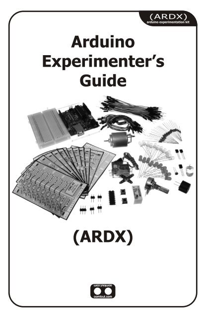
(<strong>ARDX</strong>)arduino experimentation kitArduinoExperimenter’sGuide(<strong>ARDX</strong>)
A Few WordsAbout this KitThe overall goal of this kit is fun. Beyond this, the aim is to getyou comfortable using a wide range of electronic componentsthrough small, simple and easy circuits. The focus is to geteach circuit working then giving you the tools to figure out why.If you encounter any problems, want to ask a question, or wouldlike to know more about any part, extra help is only an e-mail away help@oomlout.com.About Open Source HardwareAll of .:oomlout:.'s projects are open source. What does this mean? It means everythinginvolved in making this kit, be it this guide, 3D models, or code is available for free download.But it goes further, you're also free to reproduce and modify any of this material, then distributeit for yourself. The catch? Quite simple; it is released under a Creative Commons (By - ShareAlike) license. This means you must credit .:oomlout:. in your design and share yourdevelopments in a similar manner. Why? We grew up learning and playing with open sourcesoftware and the experience was good fun, we think it would be lovely if a similar experiencewas possible with physical things.(more details on the Creative Commons CC (By - Share Alike) License can be found at )( http://tinyurl.com/2dkzmd )About .: oomlout :.We’re a plucky little design company focusing on producing“delightfully fun open source products”To check out what we are up tohttp://www.oomlout.comAbout ProblemsWe strive to deliver the highest level of quality in each and every thing we produce. If you everfind an ambiguous instruction, a missing piece, or would just like to ask a question, we’ll try ourbest to help out. You can reach us at:help@oomlout.com(we like hearing about problems it helps us improve future versions)Thanks For Choosing .:oomlout:.
.: Where to Find Everything :.TBCNtable of contentsBefore We Start{ASEM} Assembling the Pieces 02{INST} Installing the Software 03{PROG} A Small Programming Primer 04{ELEC} A Small Electronics Primer 06The Circuits{CIRC01} Getting Started - (Blinking LED) 08{CIRC02} 8 LED Fun - (Multiple LEDs) 10{CIRC03} Spin Motor Spin - (Transistor and Motor) 12{CIRC04} A Single Servo - (Servos) 14{CIRC05} 8 More LEDs - (74HC595 Shift Register) 16{CIRC06} Music - (Piezo Elements) 18{CIRC07} Button Pressing - (Pushbuttons) 20{CIRC08} Twisting - (Potentiometers) 22{CIRC09} Light - (Photo Resistors) 24{CIRC10} Temperature - (TMP36 Temperature Sensor) 26{CIRC11} Larger Loads - (Relays) 2801
01 ASEMassembling thepieces.: Putting It Together :.Arduino Holderx1Breadboardx1Arduinox13mm x 10mm boltx23mm nutx402.: For an introduction to what an Arduino is visit :..: http://tinyurl.com/9txjmh :.
.: Installing the IDE :.This is the program used to write programs for the Arduino (meta?).It may seem a little daunting at first but once you have it installedand start playing around, its secrets will reveal themselves02 INSTinstalling(software and hardware)Step 1: Download the softwareGotohttp://arduino.cc/en/Main/SoftwareAnd download the software for your operating systemWindows XPMac OSXStep 2: Unzip the SoftwareUnziparduino-00 -win.zip (Recommended Pathc:\Program Files\ - version #)Step 2: Unzip the SoftwareUnzip (double click)arduino-00-mac.zip ( - version #)Move Foldermove /arduino-00/ to //Applications/Step 3: Shortcut IconOpenc:\program files\arduino-00 (Right ClickArduino.exe (send to>Desktop (create shortcut) )\ - version #)Step 3: Alias IconsOpen//Applications/arduino-00 (Command ClickMake AliasDrag to Desktop/ - version #)Step 4: Plug In Your ArduinoPlug your Arduino in:using the included USB cable, plug your Arduino board into afree USB portWait for a box to pop upStep 4: Install DriversGoto//Applications/Arduino-00/drivers/Double Click & InstallFTDIUSBSerialDriver_V2_2_9_Intel.dmg(V2_1_9.dmg if not an Intel Mac)RestartStep 5: Add new HardwareSkip searching the internet(click the next box when prompted to do so)Install from a Specific destination(click “Install from a list or specific location (Advanced))Choose the Locationc:\program files\arduino-00\drivers\FTDI USB Drivers\FinishedStep 5: Plug In Your ArduinoPlug your Arduino in:using the included USB cable, plug your Arduino board into afree USB port.: NOTE: :..: Encountering problems? :..: Would like more details? Using Linux? :..:http://tinyurl.com/r99d8u :.03
03 PROGprogrammingprimer.: A Small Programming Primer:.Arduino Programming in BriefThe Arduino is programmed in the C language. This is a quick little primer targeted at peoplewho have a little bit of programing experience and just need a briefing on the ideosyncrocies ofC and the Arduino IDE. If you find the concepts a bit daunting, don't worry, you can start goingthrough the circuits and pick up most of it along the way. For a more in depth intro theArduino.cc website is a great resource (the foundations page http://tinyurl.com/954pun)StructureEach Arduino program(often called a sketch) hastwo required functions(also called routines).void setup(){ }All the code between the twocurly brackets will be run oncewhen your Arduino programfirst runs.void loop(){ }This function is run after setuphas finished. After it has runonce it will be run again, andagain, until power is removed.SyntaxOne of the slightlyfrustrating elements of C isits formating requirements(this also makes it verypowerful). If you rememberthe following you should bealright.// (single line comment)It is often useful to write notesto yourself as you go alongabout what each line of codedoes. To do this type two backslashes and everything until theend of the line will be ignored byyour program.{ } (curly brackets)Used to define when a block ofcode starts and ends (used infunctions as well as loops)/* */(multi line comment)If you have a lot to say you canspan several lines as acomment. Everything betweenthese two symbols will beignored in your program.; (semicolon)Each line of code must beended with a semicolon (amissing semicolon is often thereason for a programmerefusing to compile)VariablesA program is nothing morethan instructions to movenumbers around in anintelligent way. Variables areused to do the movingboolean (boolean)A simple True or False variable.Useful because it only uses onebit of RAM.04int (integer)The main workhorse, stores anumber in 2 bytes (16 bits).Has no decimal places and willstore a value between -32,768and 32,768.float (float)Used for floating point math(decimals). Takes 4 bytes (32bits) of RAM and has a rangebetween -3.4028235E+38 and3.4028235E+38.long (long)Used when an integer is notlarge enough. Takes 4 bytes(32 bits) of RAM and has arange between -2,147,483,648and 2,147,483,648.char (character)Stores one character using theASCII code (ie 'A' = 65). Usesone byte (8 bits) of RAM. TheArduino handles strings as anarray of char’s
.:For a full programming reference visit:.http://tinyurl.com/882oxm03 PROGprogrammingprimerMaths OperatorsOperators used formanipulating numbers.(they work like simplemaths)= (assignment) makes something equal to something else (eg. x =10 * 2 (x now equals 20))% (modulo) gives the remainder when one number is divided byanother (ex. 12 % 10 (gives 2))+ (addition)- (subtraction)* (multiplication)/ (division)Comparison OperatorsOperators used for logicalcomparison== (equal to) (eg. 12 == 10 is FALSE or 12 == 12 is TRUE)!= (not equal to) (eg. 12 != 10 is TRUE or 12 != 12 is FALSE)< (less than) (eg. 12 < 10 is FALSE or 12 < 12 is FALSE or 12 < 14 is TRUE)> (greater than) (eg. 12 > 10 is TRUE or 12 > 12 is FALSE or 12 > 14 isFALSE)Control StructurePrograms are reliant oncontrolling what runsnext, here are the basiccontrol elements (thereare many more online)if(condition){ }else if( condition ){ }else { }This will execute the code betweenthe curly brackets if the condition istrue, and if not it will test the elseif condition if that is also false theelse code will execute.for(int i = 0; i
04 ELECelectronicsprimer.: A Small Electronics Primer:.Electronics in BriefNo previous electronic experience is required to have fun with this kit. Here are a few detailsabout each component to make identifying, and perhaps understanding them, a bit easier. If atany point you are worried about how a component is used or why its not working the internetoffers a treasure trove of advice, or we can be contacted at help@oomlout.comComponent DetailsLED(Light Emitting Diode)What it Does:No. of Leads:Emits light when a small current is passed 2 (one longer this one connects to positive)through it. (only in one direction)Things to watch out for:Identifying: - Will only work in one directionLooks like a mini light bulb. - Requires a current limiting resistorMore Details on Wikipedia:http://tinyurl.com/zhpyvDiode What it Does: No. of Leads:The electronic equivalent of a one way 2valve. Allowing current to flow in one Things to watch out for:direction but not the other. - Will only work in one direction (current willIdentifying:flow if end with the line is connected to ground)Usually a cylinder with wires extending from More Details on Wikipedia:either end. (and an off center line indicating polarity)http://tinyurl.com/ysz57bResistorsWhat it Does: No. of Leads:Restricts the amount of current that can flow 2through a circuit.Things to watch out for:Identifying: - Easy to grab the wrong value (double checkCylinder with wires extending from eitherthe colors before using)end. The resistance value is displayed using More Details on Wikipedia:a color coding system (for details see next http://tinyurl.com/cmeqw5page)Transistor What it Does: No. of Leads:Uses a small current to switch or amplify a 3 (Base, Collector, Emitter)much larger current.Things to watch out for:Identifying: - Plugging in the right way round.(also aComes in many different packages but youcurrent limiting resistor is often needed on the base pin)can read the part number off the package. More Details on Wikipedia:(P2N2222AG in this kit and find a datasheet online) http://tinyurl.com/eazknHobby ServoWhat it Does:No. of Leads:Takes a timed pulse and converts it into an 3angular position of the output shaft.Things to watch out for:Identifying: - The plug is not polarized so make sure itA plastic box with 3 wires coming out one is plugged in the right way.side and a shaft with a plastic horn out the More Details:top. http://tinyurl.com/4zo4heDC Motor What it Does: No. of Leads:06Spins when a current is passed through it. 2Identifying:Things to watch out for:This one is easy, it looks like a motor. Usually - Using a transistor or relay that is rated fora cylinder with a shaft coming out of one the size of motor you're using.endMore Details on Wikipedia:http://tinyurl.com/d826yh
Component Details (cont.)Piezo ElementWhat it Does:No. of Leads:A pulse of current will cause it to click a 2stream of pulses will cause it to emit a tone. Things to watch out for:Identifying: - Difficult to misuse.In this kit it comes in a little black barrel, but More Details:sometimes they are just a gold disc. http://tinyurl.com/38crmu04 ELECelectronicsprimerIC (Integrated Circuit)What it Does:Packages any range of complicatedelectronics inside, an easy to use form factorIdentifying:The part ID is written on the outside of thepackage. (this sometimes requires a lot oflight or a magnifying glass to read)No. of Leads:2 - 100s (in this kit there is one with 3 (TMP36) andone with 16 (74HC595)Things to watch out for:- Proper orientation.(look for marks showing pin 1)More Details:http://tinyurl.com/87k4dPushbutton What it Does:No. of Leads:Completes a circuit when it is pressed 4Identifying:Things to watch out for:A little square with leads out the bottom and - these are almost square so can bea button on the top.inserted 90 degrees off angle.More Details:http://tinyurl.com/cmts7dPotentiometerPhoto ResistorWhat it Does:No. of Leads:Produces a variable resistance dependant on 3the angular position of the shaft.Things to watch out for:Identifying: - Accidentally buying logarithmic scale.They can be packaged in many different More Details:form factors, look for a dial to identify. http://tinyurl.com/28pbhdWhat it Does:No. of Leads:Produces a variable resistance dependant on 2the amount of incident light.Things to watch out for:Identifying: - Remember it needs to be in a voltageUsually a little disk with a clear top and a divider before it provides a useful input.curvy line underneath.More Details:http://tinyurl.com/c2wdkwResistor Color CodeExamples:green-blue-brown - 560 ohmsred-red-red - 2 200 ohms (2.2k)brown-black-orange - 10 000 ohms (10k)first digitsecond digit# of zerostolerance0 - Black 5 - Green 20% - none1 - Brown 6 - Blue 10% - silver2 - Red 7 - Purple 5% - gold3 - Orange 8 - Grey4 - Yellow 9 - WhiteLead ClippingSome components in this kit come with very long wireleads. To make them more compatible with a breadboarda couple of changes are required.LEDs:Clip the leads so the long lead is ~7mm long and theshort one is ~5mmResistors:Bend the leads down so they are 90 degrees to thecylinder. Then snip them so they are ~6mm long.Other Components:Other components may need clippinguse your discretion when doing so.07
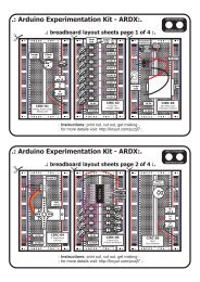
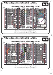
CIRC-01.:Getting Started:..:(Blinking LED):.What We’re Doing:LED’s (light emitting diodes) are used in all sorts of cleverthings which is why we have included them in this kit. We willstart off with something very simple, turning one on and off,repeatedly, producing a pleasant blinking effect. To get startedgrab the parts listed below, pin the layout sheet to your breadboard and then plug everything in.Once the circuit is assembled you'll need to upload the program. To do this plug the Arduinoboard into your USB port. Then select the proper port in Tools > Serial Port > (the commport of your Arduino). Next upload the program by going to File > Upload to I/O Board(ctrl+U). Finally bask in the glory and possibility that controlling lights offers.If you are having trouble uploading, a full trouble shooting guide can be found here: http://tinyurl.com/89s2poThe Circuit:Parts:CIRC-01Breadboard sheetx12 Pin Headerx410mm LEDx1Wire560 Ohm ResistorGreen-Blue-Brownx1Schematic:Arduinopin 13+longer leadLED(light emitting diode)resistor (560ohm)(blue-green-brown)gnd(ground) (-)The Internet.:download:.breadboard layout sheethttp://tinyurl.com/qukhvc.:view:.assembling videohttp://tinyurl.com/cwhx2708
Code (no need to type everything in just)File > Sketchbook > Examples > Digital > Blink(example from the great arduino.cc site check it out for other ideas)CIRC-01/** Blink** The basic Arduino example. Turns an LED on for one second,* then off for one second, and so on... We use pin 13 because,* depending on your Arduino board, it has either a built-in LED* or a built-in resistor so that you need only an LED.** http://www.arduino.cc/en/Tutorial/Blink*/int ledPin = 13; // LED connected to digital pin 13void setup()// run once, when the sketch starts{pinMode(ledPin, OUTPUT); // sets the digital pin as output}void loop()// run over and over again{digitalWrite(ledPin, HIGH); // sets the LED on}delay(1000);digitalWrite(ledPin, LOW);delay(1000);// waits for a second// sets the LED off// waits for a secondNot Working? (3 things to try)LED Not Lighting Up?LEDs will only work in onedirection.try taking it out and twisting it180 degrees.(no need to worry, installing itbackwards does no permanentharm)Program Not UploadingThis happens sometimes,the most likely cause is aconfused serial port, youcan change this intools>serial port>Still No Success?A broken circuit is no fun, sendus an e-mail and we will getback to you as soon as we can.help@oomlout.comMaking it BetterChanging the pin:The LED is connected to pin 13 but we can use any ofthe Arduino’s pins. To change it take the wire pluggedinto pin 13 and move it to a pin of your choice (from 0-Control the Brightness:Along with digital (on/off) control the Arduino can controlsome pins in an analog (brightness) fashion. (more details onthis in later circuits). To play around with it.13) (you can also use analog 0-5 analog 0 is 14...) Change the LED to pin 9: (also change the wire)Then in the code change the line:ledPin = 13; -> int ledPin = 9;int ledPin = 13; -> int ledPin = newpin; Replace the code inside the { }'s of loop() with this:Then upload the sketch: (ctrl-u)analogWrite(ledPin, new number);Change the Blink Time: (new number) = any number between 0 and 255.Unhappy with one second on one second off?0 = off, 255 = on, in between = different brightnessIn the code change the lines:digitalWrite(ledPin, HIGH);delay(time on); //(seconds * 1000)digitalWrite(ledPin, LOW);delay(time off); //(seconds * 1000)Fading:We will use another included example program. To open go to.File > Sketchbook > Examples > Analog > FadeThen upload to your board and watch as the LED fades in andthen out.More, More, More:More details, where to buy more parts, where to ask more questions.http://tinyurl.com/cmn5nh09
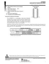
CIRC-02.:8 LED Fun:..:Multiple LED’s:.What We’re Doing:We have caused one LED to blink, now its time to up thestakes. Lets connect eight. We'll also have an opportunity tostretch the Arduino a bit by creating various lighting sequences.This circuit is also a nice setup to experiment with writing yourown programs and getting a feel for how the Arduino works.Along with controlling the LEDs we start looking into a few simple programming methods tokeep your programs small.for() loops - used when you want to run a piece of code several times.arrays[] - used to make managing variables easier (its a group of variables)The Circuit:Parts:CIRC-02Breadboard sheetx12 Pin Headerx45mm GreenLEDx8Wire560 Ohm ResistorGreen-Blue-Brownx8Schematic:pin 2 pin 3 pin 4 pin 5LEDgndresistor560ohmpin 6 pin 7 pin 8 pin 9LEDgndresistor560ohmThe Internet.:download:.breadboard layout sheethttp://tinyurl.com/d4gmov.:view:.assembling videohttp://tinyurl.com/coafoh10
Code (no need to type everything in just)Download the Code from ( http://tinyurl.com/dkpxbn )(and then copy the text and paste it into an empty Arduino Sketch)CIRC-02//LED Pin Variables* will then turn them offint ledPins[] = {2,3,4,5,6,7,8,9};//An array to hold thevoid oneAfterAnotherNoLoop(){//pin each LED is connected to int delayTime = 100;/ / i . e . L E D # 0 i s c o n n e c t e d t o p i n 2 / / t h e t i m e ( i n m i l l i s e c o n d s ) t o p a u s e//between LEDsvoid setup() digitalWrite(ledPins[0], HIGH); //Turns on LED #0{ //(connected to pin 2)for(int i = 0; i < 8; i++){ delay(delayTime); //waits delayTime milliseconds//this is a loop and will repeat eight times ...pinMode(ledPins[i],OUTPUT); ...//we use this to set LED pins to output digitalWrite(ledPins[7], HIGH); //Turns on LED #7} //(connected to pin 9)} delay(delayTime); //waits delayTime milliseconds//Turns Each LED Offvoid loop() // run over and over again digitalWrite(ledPins[7], LOW); //Turns off LED #7{ delay(delayTime); //waits delayTime millisecondsoneAfterAnotherNoLoop(); ...//this will turn on each LED one by//one then turn each oneoff-----more code in the downloadable version------//oneAfterAnotherLoop();//this does the same as onAfterAnotherNoLoop//but with much less typing//oneOnAtATime();//inAndOut();}/** oneAfterAnotherNoLoop() - Will light one then* delay for delayTime then light the next LED itNot Working? (3 things to try)Some LEDs Fail to LightIt is easy to insert an LEDbackwards. Check the LEDsthat aren't working and ensurethey the right way around.Operating out of sequenceWith eight wires it's easy to crossa couple. Double check that thefirst LED is plugged into pin 2 andeach pin there after.Starting AfreshIts easy to accidentallymisplace a wire withoutnoticing. Pulling everything outand starting with a fresh slateis often easier than trying totrack down the problem.Making it BetterSwitching to Loops:in the loop() function there are 4 lines. The lastthree all start with a '//' this means the line istreated as a comment (not run). To switch theprogram to use loops change the void loop()code to://oneAfterAnotherNoLoop();oneAfterAnotherLoop();//oneOnAtATime();//inAndOut();Upload the program, and notice that nothing haschanged. You can take a look at the twofunctions, each does the same thing, but usedifferent approaches (hint the second one uses afor loop)Extra Animations:Tired of this animation? Then try the other twosample animations. Uncomment their lines andupload the program to your board and enjoy the newlight animations. (delete the slashes in front of row 3 and then 4)Testing out your own Animations:Jump into the included code and start changingthings. The main point is to turn an LED on usedigitalWrite(pinNumber, HIGH); then toturn it off use digitalWrite(pinNumber,LOW); . Type away, regardless of what you changeyou won't break anything.More, More, More:More details, where to buy more parts, where to ask more questions.http://tinyurl.com/d2hrud11
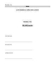
CIRC-03.:Spin Motor Spin:..:Transistor & Motor:.What We’re Doing:The Arduino's pins are great for directly controlling small electricitems like LEDs. However, when dealing with larger items (like atoy motor or washing machine), an external transistor is required.A transistor is incredibly useful. It switches a lot of current using amuch smaller current. A transistor has 3 pins. For a negative type(NPN) transistor you connect your load to collector and the emitter to ground. Then when a smallcurrent flows from base to the emitter a current will flow through the transistor and your motor willspin (this happens when we set our Arduino pin HIGH). There are literally thousands of differenttypes of transistors, allowing every situation to be perfectly matched. We have chosen a P2N2222AGa rather common general purpose transistor. The important factors in our case are that its maximumvoltage (40 v) and its maximum current (600 milliamp) are both high enough for our toy motor (fulldetails can be found on its datasheet http://tinyurl.com/o2cm93 )note: the transistor we use has a in order: Base Collector Emitter pinout (differing from some other popular transistors)(The 1N4001 diode is acting as a flyback diode for details on why its there visit: http://tinyurl.com/b559mx)The Circuit:Parts:CIRC-03Breadboard sheetx12.2k Ohm ResistorRed-Red-Redx12 Pin Headerx4Toy Motorx1TransistorP2N2222AG (TO92)x1Diode(1N4001)x1WireSchematic:Arduinopin 9the transistor will haveP2N2222AG printed on it(some variations will havethe pin assignment reversed)resistor(2.2kohm)BaseCollectorDiodeMotorTransistorP2N2222AGEmittergnd(ground) (-)+5 voltsThe Internet.:download:.breadboard layout sheethttp://tinyurl.com/d6jv63.:view:.assembling videohttp://tinyurl.com/djapjg12
Code (no need to type everything in just)Download the Code from ( http://tinyurl.com/dagyrb )(then simply copy the text and paste it into an empty Arduino Sketch)int motorPin = 9; //pin the motor is connected toCIRC-03void setup() //runs oncevoid motorOnThenOffWithSpeed(){{ int onSpeed = 200;// a number betweenpinMode(motorPin, OUTPUT);//0 (stopped) and 255 (full speed)} int onTime = 2500;int offSpeed = 50;// a number betweenvoid loop() // run over and over again //0 (stopped) and 255 (full speed){ int offTime = 1000;motorOnThenOff(); analogWrite(motorPin, onSpeed);//motorOnThenOffWithSpeed(); // turns the motor On//motorAcceleration(); delay(onTime); // waits for onTime milliseconds} analogWrite(motorPin, offSpeed);// turns the motor Off/* delay(offTime); // waits for offTime milliseconds* motorOnThenOff() - turns motor on then off }used forvoid motorAcceleration(){* the blinking LED)int delayTime = 50; //time between each speed step*/for(int i = 0; i < 256; i++){void motorOnThenOff(){//goes through each speed from 0 to 255int onTime = 2500; //on timeanalogWrite(motorPin, i); //sets the new speedint offTime = 1000; //off timedelay(delayTime);// waits for delayTime millisecondsdigitalWrite(motorPin, HIGH);}// turns the motor Onfor(int i = 255; i >= 0; i--){delay(onTime); // waits for onTime milliseconds//goes through each speed from 255 to 0digitalWrite(motorPin, LOW);analogWrite(motorPin, i); //sets the new speed// turns the motor Offdelay(delayTime);//waits for delayTime millisecondsdelay(offTime);// waits for offTime milliseconds }}}* (notice this code is identical to the code weNot Working? (3 things to try)Motor Not Spinning?if you sourced your owntransistor, double check withthe data sheet that the pinoutis compatible with a P2N2222A(many are reversed)Still No Luck?if you sourced your own motor,double check that it will workwith 5 volts and that it does notdraw too much power.Still Not Working?Sometimes the Arduino boardwill disconnect from thecomputer. Try un-plugging andthen re-plugging it into yourUSB port.Making it BetterControlling Speed:We played with the Arduino's ability to control thebrightness of an LED earlier now we will use the samefeature to control the speed of our motor. The arduinodoes this using something called Pulse WidthModulation (PWM). This relies on the Arduino's ability tooperate really really fast. Rather than directly controllingthe voltage coming from the pin the Arduino will switchthe pin on and off very quickly. In the computer worldthis is going from 0 to 5 volts many times a second, butin the human world we see it as a voltage. For exampleif the Arduino is PWM'ing at 50% we see the lightdimmed 50% because our eyes are not quick enough tosee it flashing on and off. The same feature works withtransistors. Don't believe me? Try it out.In the loop() section change it to this// motorOnThenOff();motorOnThenOffWithSpeed();//motorAcceleration();Then upload the programme. You can change the speeds bychanging the variables onSpeed and offSpeedAccelerating and decelerating:Why stop at two speeds, why not accelerate and deceleratethe motor. To do this simply change the loop() code to read// motorOnThenOff();// motorOnThenOffWithSpeed();motorAcceleration();Then upload the program and watch as your motor slowlyaccelerates up to full speed then slows down again. If youwould like to change the speed of acceleration change thevariable delayTime (larger means a longer acceleration time)More, More, More:More details, where to buy more parts, where to ask more questions.http://tinyurl.com/d4wht713
CIRC-04.:A Single Servo:..:Servos:.What We’re Doing:Spinning a motor is good fun but when it comes to projectswhere motion control is required they tend to leave us wantingmore. The answer? Hobby servos. They are mass produced,widely available and cost anything from a couple of dollars tohundreds. Inside is a small gearbox (to make the movement more powerful) and someelectronics (to make it easier to control). A standard servo is positionable from 0 to 180degrees. Positioning is controlled through a timed pulse, between 1.25 milliseconds (0 degrees)and 1.75 milliseconds (180 degrees) (1.5 milliseconds for 90 degrees). Timing varies betweenmanufacturer. If the pulse is sent every 25-50 milliseconds the servo will run smoothly. One ofthe great features of the Arduino is it has a software library that allows you to control twoservos (connected to pin 9 or 10) using a single line of code.The Circuit:Parts:CIRC-04Breadboard sheetx12 Pin Headerx43 Pin Headerx1WireMini Servox1Schematic:Arduinopin 9Mini Servosignal(orange)gnd(black/brown)+5v(red)gnd(ground) (-)+5 volts(5V)The Internet.:download:.breadboard layout sheethttp://tinyurl.com/db5fcm.:view:.assembling videohttp://tinyurl.com/d5295414
Code (no need to type everything in just)File > Sketchbook > Examples > Library-Servo > Sweep(example from the great arduino.cc site check it out for other great ideas)CIRC-04// Sweep// by BARRAGAN #include Servo myservo; // create servo object to control a servoint pos = 0; // variable to store the servo positionvoid setup() {myservo.attach(9); // attaches the servo on pin 9 to the servo object}void loop() {for(pos = 0; pos < 180; pos += 1) // goes from 0 degrees to 180 degrees{ // in steps of 1 degreemyservo.write(pos);// tell servo to go to position in variable 'pos'delay(15);// waits 15ms for the servo to reach the position}for(pos = 180; pos>=1; pos-=1) // goes from 180 degrees to 0 degrees{myservo.write(pos);// tell servo to go to position in variable 'pos'delay(15);// waits 15ms for the servo to reach the position}}Not Working? (3 things to try)Servo Not Twisting?Even with colored wires it is stillshockingly easy to plug a servoin backwards. This might be thecase.Still not WorkingA mistake we made a time ortwo was simply forgetting toconnect the power (red andbrown wires) to +5 volts andground.Frustration?Shoot us an e-mail, this circuitis both simple and complex atthe same time. We want tohear about problems you haveso we can address them infuture editions.help@oomlout.comMaking it BetterPotentiometer Control:void loop() {We have yet to experiment with inputs but if you would like to int pulseTime = 2100; //(the number of microseconds//to pause for (1500 90 degreesread ahead, there is an example program File > Sketchbook// 900 0 degrees 2100 180 degrees)> Examples > Library-Servo > Knob. This uses adigitalWrite(servoPin, HIGH);delayMicroseconds(pulseTime);potentiometer (CIRC08) to control the servo. You can finddigitalWrite(servoPin, LOW);delay(25);instructions online here: http://tinyurl.com/dymsk2 }Self Timing:While it is easy to control a servo using the Arduino's includedlibrary sometimes it is fun to figure out how to programsomething yourself. Try it. We're controlling the pulse directlyso you could use this method to control servos on any of theArduino's 20 available pins (you need to highly optimize thiscode before doing that).int servoPin = 9;void setup(){pinMode(servoPin,OUTPUT);}Great Ideas:Servos can be used to do all sorts of great things, here are a few ofour favorites.Xmas Hit Counterhttp://tinyurl.com/37djhqOpen Source Robotic Arm (uses a servo controller as well as the Arduino)http://tinyurl.com/ckm3wdServo Walkerhttp://tinyurl.com/da5jfeMore, More, More:More details, where to buy more parts, where to ask more questions.http://tinyurl.com/djwlop15
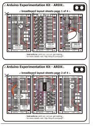
CIRC-05.:8 More LEDs:..:74HC595 Shift Register:.What We’re Doing:Time to start playing with chips. Or integrated circuits (ICs) as they like to becalled. The external packaging of a chip can be very deceptive for example thechip on the Arduino board (a micro controller) and the one we will use in thiscircuit (a shift register) look very similar but are in fact rather different, forexample the price of the Atmega chip on the arduino board is a few dollars while the74hc595 is a couple dozen cents. It's a good introductory chip, and once your comfortable playing around with it and itsdatasheet (available online http://tinyurl.com/pr42xe ) the world of chips will be your oyster. The shift register (also calleda serial to parallel converter), will give you an additional 8 outputs (to control LEDs and the like) using only three arduinopins. They can also be linked together to give you a nearly unlimited number of outputs using the same four pins. To useit you “clock in” the data and then latch lock it in (latch it). To do this you set the data pin to either HIGH or LOW, pulsethe clock, then set the data pin again and pulse the clock repeating until you have shifted out 8 bits of data. Then youpulse the latch and the 8 bits are transferred to the shift registers pins. It sounds complicated but is really simple onceyou get the hang of it.(for a more in depth look at how a shift register works visit: http://tinyurl.com/56uvv7 )The Circuit:Parts:CIRC-05Breadboard sheetx1560 Ohm ResistorGreen-Blue-Brownx82 Pin Headerx4Red LEDx8Shift Register74HC595x1Wirepin4Schematic:+5 voltspin3pin274HC595+5Vdataclocklatchgnd01234567LEDresistor(560ohm)gnd(ground) (-)There is a half mooncutout, this goes at the topThe Internet.:download:.breadboard layout sheethttp://tinyurl.com/d8xepz..:view:.assembling videohttp://tinyurl.com/c2enkv16
Code (no need to type everything in just)Download the Code from ( http://tinyurl.com/cv4fjt )(copy the text and paste it into an empty Arduino Sketch)//Pin Definitions//The 74HC595 uses a protocol called SPI//Which has three pinsint data = 2;int clock = 3;int latch = 4;digitalWrite(latch, LOW);CIRC-05//Pulls the chips latch lowshiftOut(data, clock, MSBFIRST, value);void setup() //runs once //Shifts out 8 bits to the shift register{pinMode(data, OUTPUT);pinMode(clock, OUTPUT);digitalWrite(latch, HIGH);pinMode(latch, OUTPUT); } //Pulls the latch high displaying the data}void loop() // run over and over again{ ---------- More Code Online ----------int delayTime = 100;//delay between LED updatesfor(int i = 0; i < 256; i++){updateLEDs(i);delay(delayTime); }}/** updateLEDs() - sends the LED states set* in value to the 74HC595 sequence*/void updateLEDs(int value){Not Working? (3 things to try)The Arduino’s PowerLED goes outThis happened to us a coupleof times, it happens when thechip is inserted backwards. Ifyou fix it quickly nothing willbreak.Not Quite WorkingSorry to sound like a brokenrecord but it is probablysomething as simple as acrossed wire.Frustration?Shoot us an e-mail, this circuitis both simple and complex atthe same time. We want tohear about problems you haveso we can address them infuture editions.help@oomlout.comMaking it BetterDoing it the hard way:An Arduino makes rather complex actions very easy, shifting out datais one of these cases. However one of the nice features of anArduino is you can make things as easy or difficult as you like. Letstry an example of this. In your loop switch the line.updateLEDs(i) -> updateLEDsLong(i);Upload the program and notice nothing has changed. If you look atthe code you can see how we are communicating with the chip onebit at a time. (for more details http://tinyurl.com/3augzd )Controlling Individual LEDs:Time to start controlling the LEDs in a similar method as we did inCIRC02. As the eight LED states are stored in one byte (an 8 bitvalue) for details on how this works try http://tinyurl.com/6vz53. AnArduino is very good at manipulating bits and there are an entire setof operators that help us out. Details on bitwise maths (http://tinyurl.com/br8dd )Our implementation.Replace the loop() code withint delayTime = 100; //the number ofmilliseconds to delay//between LED updatesfor(int i = 0; i < 8; i++){changeLED(i,ON);delay(delayTime);}for(int i = 0; i < 8; i++){changeLED(i,OFF);delay(delayTime);}And upload this will cause the lights to light up one after another and thenoff in a similar manner. Check the code and wikipedia to see how it works,or shoot us an e-mail if you have questions.More Animations:Now things get more interesting. If you look back to the code from CIRC02(8 LED Fun) you see we change the LEDs using digitalWrite(led, state), thisis the same format as the routine we wrote changeLED(led, state). You canuse the animations you wrote for CIRC02 by copying the code into thissketch and changing all the digitalWrite()'s to changeLED()'s. Powerful?Very. (you'll also need to change a few other things but follow the compileerrors and it works itself out)More, More, More:More details, where to buy more parts, where to ask more questions.http://tinyurl.com/dkjno317
CIRC-06.:Music:..:Piezo Elements:.What We’re Doing:To this point we have controlled light, motion, andelectrons, Lets tackle sound next. But sound is ananalog phenomena, how will our digital Arduino cope?We will once again rely on its incredible speed which willlet it mimic analog behavior. To do this, we will attach a piezo element to one ofthe Arduino's digital pins. A piezo element makes a clicking sound each time itis pulsed with current. If we pulse it at the right frequency (for example 440times a second to make the note middle A) these clicks will run together toproduce notes. Lets get to experimenting with it and get your Arduino playingThe Circuit:Parts:CIRC-06Breadboard sheetx12 Pin Headerx4Piezo Elementx1WireSchematic:Arduinopin 9PiezoElementgnd(ground) (-)The Internet.:download:.breadboard layout sheethttp://tinyurl.com/c94aml.:view:.assembling videohttp://tinyurl.com/mnh33o18
Code (no need to type everything in just)File > Sketchbook > Examples > Digital > Melody(example from the great arduino.cc site check it out for other great ideas)CIRC-06/* Melody* (cleft) 2005 D. Cuartielles for K3** This example uses a piezo speaker to play melodies. It sends digitalWrite(speakerPin, LOW);* a square wave of the appropriate frequency to the piezo, delayMicroseconds(tone);* generating the corresponding tone. }* }* The calculation of the tones is made following the* mathematical operation: void playNote(char note, int duration) {* char names[] = { 'c', 'd', 'e', 'f', 'g', 'a', 'b', 'C' };* timeHigh = period / 2 = 1 / (2 * toneFrequency) int tones[] = { 1915, 1700, 1519, 1432, 1275, 1136, 1014, 956* };* where the different tones are described as in the table: // play the tone corresponding to the note name* for (int i = 0; i < 8; i++) {* note frequency period timeHigh if (names[i] == note) {* c 261 Hz 3830 1915 playTone(tones[i], duration);* d 294 Hz 3400 1700 }* e 329 Hz 3038 1519 }* f 349 Hz 2864 1432 }* g 392 Hz 2550 1275* a 440 Hz 2272 1136 void setup() {* b 493 Hz 2028 1014 pinMode(speakerPin, OUTPUT);* C 523 Hz 1912 956 }** http://www.arduino.cc/en/Tutorial/Melody void loop() {*/ for (int i = 0; i < length; i++) {int speakerPin = 9;if (notes[i] == ' ') {delay(beats[i] * tempo); // rest} else {int length = 15; // the number of notes playNote(notes[i], beats[i] * tempo);char notes[] = "ccggaagffeeddc "; // a space represents a rest }int beats[] = { 1, 1, 1, 1, 1, 1, 2, 1, 1, 1, 1, 1, 1, 2, 4 }; // pause between notesint tempo = 300; delay(tempo / 2); }void playTone(int tone, int duration) {}for (long i = 0; i < duration * 1000L; i += tone * 2) {digitalWrite(speakerPin, HIGH);delayMicroseconds(tone);Not Working? (3 things to try)No SoundGiven the size and shape of thepiezo element it is easy to missthe right holes on thebreadboard. Try doublechecking its placement.Can't Think While theMelody is Playing.Just pull up the piezo elementwhilst you think, upload yourprogram then plug it back in.Tired of Twinkle TwinkleLittle Star?The code is written so you caneasily add your own songs,check out the code below toget started.Making it BetterPlaying with the speed:char names[] = { 'c', 'd', 'e', 'f', 'g', 'a', 'b',The timing for each note is calculated based on variables, 'C' };int tones[] = { 1915, 1700, 1519, 1432, 1275, 1136,as such we can tweak the sound of each note or the 1014, 956 };timing. To change the speed of the melody you need to Composing your own melodies:change only one line.The program is pre-set to play 'Twinkle Twinkle Little Star'int tempo = 300; ---> int tempo = (new #)however the way it is programmed makes changing the songChange it to a larger number to slow the melody down,easy. Each song is defined in one int and two arrays, the intor a smaller number to speed it up.Tuning the notes:length defines the number of notes, the first array notes[]If you are worried about the notes being a little out of defines each note, and the second beats[] defines how longtune this can be fixed as well. The notes have been each note is played. Some Examples:calculated based on a formula in the comment block atTwinkle Twinkle Little Starint length = 15;the top of the program. But to tune individual notes just char notes[] = "ccggaagffeeddc ";int beats[] = { 1, 1, 1, 1, 1, 1, 2, 1, 1, 1, 1,adjust their values in the tones[] array up or down 1, 1, 2, 4 };until they sound right. (each note is matched by its name Happy Birthday (first line)int length = 13;in the names[] (array ie. c = 1915 )char notes[] = "ccdcfeccdcgf ";int beats[] = {1,1,1,1,1,2,1,1,1,1,1,2,4};More, More, More:More details, where to buy more parts, where to ask more questions.http://tinyurl.com/cpf6so19
CIRC-07.:Button Pressing:..:Pushbuttons:.What We’re Doing:Up to this point we have focused entirely on outputs, time toget our Arduino to listen, watch and feel. We'll start with asimple pushbutton. Wiring up the pushbutton is simple. There isone component, the pull up resistor, that might seem out of place.This is included because an Arduino doesn't sense the same way we do (ie button pressed,button unpressed). Instead it looks at the voltage on the pin and decides whether it is HIGH orLOW. The button is set up to pull the Arduino's pin LOW when it is pressed, however, when thebutton is unpressed the voltage of the pin will float (causing occasional errors). To get theArduino to reliably read the pin as HIGH when the button is unpressed, we add the pull upresistor.(note: the first example program uses only one of the two buttons)The Circuit:Parts:CIRC-07Breadboard sheetx110k Ohm ResistorBrown-Black-Redx22 Pin Headerx4560 Ohm ResistorGreen-Blue-Brownx1Pushbuttonx2Red LEDx1WireSchematic:Arduinopin 13LEDArduinopin 2 pin 3+5 voltsresistor(10k ohm)resistor(560ohm)pushbuttongnd(ground) (-)The Internet.:download:.breadboard layout sheethttp://tinyurl.com/dzmh8w.:view:.assembling videohttp://tinyurl.com/dnln6g20
Code (no need to type everything in just)File > Sketchbook > Examples > Digital > Button(example from the great arduino.cc site check it out for other great ideas)CIRC-07/** Button* by DojoDave ** Turns on and off a light emitting diode(LED) connected to digital * pin 13,when pressing a pushbutton attached to pin 7. ** http://www.arduino.cc/en/Tutorial/Button*/int ledPin = 13;// choose the pin for the LEDint inputPin = 2;// choose the input pin (for a pushbutton)int val = 0;// variable for reading the pin statusvoid setup() {pinMode(ledPin, OUTPUT);pinMode(inputPin, INPUT);}// declare LED as output// declare pushbutton as inputvoid loop(){val = digitalRead(inputPin); // read input valueif (val == HIGH) {// check if the input is HIGHdigitalWrite(ledPin, LOW); // turn LED OFF} else {digitalWrite(ledPin, HIGH); // turn LED ON}}Not Working? (3 things to try)Light Not Turning OnThe pushbutton is square andbecause of this it is easy to putit in the wrong way. Give it a 90degree twist and see if it startsworking.Light Not FadingA bit of a silly mistake weconstantly made, when youswitch from simple on off tofading remember to move theLED wire from pin 13 to pin 9Underwhelmed?No worries these circuits are allsuper stripped down to makeplaying with the componentseasy, but once you throw themtogether the sky is the limit.Making it BetterOn button off button:The initial example may be a little underwhelming (ie. Idon't really need an Arduino to do this), lets make it alittle more complicated. One button will turn the LED onthe other will turn the LED off. Change the code to.int ledPin = 13; // choose the pin for the LEDint inputPin1 = 3; // button 1int inputPin2 = 2; // button 2void setup() {pinMode(ledPin, OUTPUT); // declare LED as outputpinMode(inputPin1, INPUT); // make button 1 an inputpinMode(inputPin2, INPUT); // make button 2 an input}void loop(){if (digitalRead(inputPin1) == LOW) {digitalWrite(ledPin, LOW); // turn LED OFF} else if (digitalRead(inputPin2) == LOW) {digitalWrite(ledPin, HIGH); // turn LED ON}}Upload the program to your board, and start toggling theLED on and off.Fading up and down:Lets use the buttons to control an analog signal. To do this youwill need to change the wire connecting the LED from pin 13 topin 9, also change this in code.int ledPin = 13; ----> int ledPin = 9;Next change the loop() code to read.int value = 0;void loop(){if (digitalRead(inputPin1) == LOW) { value--; }else if (digitalRead(inputPin2) == LOW) { value++; }value = constrain(value, 0, 255);analogWrite(ledPin, value);delay(10);}Changing Fade Speed:If you would like the LED to fade faster or slower, there is onlyone line of code that needs changing;delay(10); ----> delay(new #);To fade faster make the number smaller, slower requires alarger number.More, More, More:More details, where to buy more parts, where to ask more questions.http://tinyurl.com/c64tmt21
CIRC-08.:Twisting:..:Potentiometers:.What We’re Doing:Along with the digital pins the Arduino has it alsohas 6 pins which can be used for analog input.These inputs take a voltage (from 0 to 5 volts) andconvert it to a digital number between 0 (0 volts) and1024 (5 volts) (10 bits of resolution). A very useful device that exploits theseinputs is a potentiometer (also called a variable resistor). When it is connectedwith 5 volts across its outer pins the middle pin will read some value between 0and 5 volts dependent on the angle to which it is turned (ie. 2.5 volts in themiddle). We can then use the returned values as a variable in our program.The Circuit:Parts:CIRC-08Breadboard sheetx1560 Ohm ResistorGreen-Blue-Brownx12 Pin Headerx4Green LEDx1Potentiometer10k ohmx1WireSchematic:Arduinopin 13+5 voltsPotentiometerLED(lightemittingdiode)Arduinoanalogpin 2resistor (560ohm)(blue-green-brown)gnd(ground) (-)The Internet.:download:.breadboard layout sheethttp://tinyurl.com/d62o7q..:view:.assembling videohttp://tinyurl.com/cormru22
Code (no need to type everything in just)File > Sketchbook > Examples > Analog > AnalogInput(example from the great arduino.cc site check it out for other great ideas)CIRC-08/** AnalogInput* by DojoDave ** Turns on and off a light emitting diode(LED) connected to digital * pin 13. The amount oftime the LED will be on and off depends on* the value obtained by analogRead(). In the easiest case we connect* a potentiometer to analog pin 2.** http://www.arduino.cc/en/Tutorial/AnalogInput*/int potPin = 2;int ledPin = 13;int val = 0;// select the input pin for the potentiometer// select the pin for the LED// variable to store the value coming from the sensorvoid setup() {pinMode(ledPin, OUTPUT); // declare the ledPin as an OUTPUT}void loop() {val = analogRead(potPin); // read the value from the sensordigitalWrite(ledPin, HIGH); // turn the ledPin ondelay(val);// stop the program for some timedigitalWrite(ledPin, LOW); // turn the ledPin offdelay(val);// stop the program for some time}Not Working? (3 things to try)Sporadically WorkingThis is most likely due to aslightly dodgy connection withthe potentiometer's pins. Thiscan usually be conquered bytaping the potentiometer down.The Control is BackwardThere are two ways to fix this,either switch the red and blackwires connected to thepotentiometer, or turn thepotentiometer around. (sorrysometimes the factory ships us abackwards potentiometer)Still BackwardYou can try operating thecircuit upside down. Sometimesthis helps.Making it BetterThreshold Switching:Then change the loop code to.Sometimes you will want to switch an output when avoid loop() {int value = analogRead(potPin) / 4;value exceeds a certain threshold. To do this with aanalogWrite(ledPin, value);}potentiometer change the loop() code to.Upload the code and watch as your LED fades in relation tovoid loop() {int threshold = 512;your potentiometer spinning. (Note: the reason we divide theif(analogRead(potPin) > threshold){ value by 4 is the analogRead() function returns a value from 0digitalWrite(ledPin, HIGH);}else{ digitalWrite(ledPin, LOW);}to 1024 (10 bits), and analogWrite() takes a value from 0 to}255 (8 bits) )This will cause the LED to turn on when the value isControlling a Servo:above 512 (about halfway), you can adjust the sensitivity This is a really neat example and brings a couple of circuitsby changing the threshold value.together. Wire up the servo like you did in CIRC-04, then openFading:the example program Knob (File > Sketchbook > ExamplesLets control the brightness of an LED directly from the> Library-Servo > Knob ), then change one line of code.potentiometer. To do this we need to first change the pin int potpin = 0; ----> int potpin = 2;the LED is connected to. Move the wire from pin 13 to Upload to your Arduino and then watch as the servo shaftpin 9 and change one line in the code.int ledPin = 13; ----> int ledPin = 9;turns as you turn the potentiometer.More, More, More:More details, where to buy more parts, where to ask more questions.http://tinyurl.com/cva3kq23
CIRC-09.:Light:..:Photo Resistors:.What We’re Doing:Whilst getting input from a potentiometer can be usefulfor human controlled experiments, what do we usewhen we want an environmentally controlled experiment?We use exactly the same principles but instead of apotentiometer (twist based resistance) we use a photo resistor (light basedresistance). The Arduino cannot directly sense resistance (it senses voltage) so weset up a voltage divider ( http://tinyurl.com/2sunta ). The exact voltage at thesensing pin is calculable, but for our purposes (just sensing relative light) we canexperiment with the values and see what works for us. A low value will occur whenthe sensor is well lit while a high value will occur when it is in darkness.The Circuit:Parts:CIRC-09Breadboard sheetx110k Ohm ResistorBrown-Black-Redx12 Pin Headerx4560 Ohm ResistorGreen-Blue-Brownx1Photo-Resistorx1Green LEDx1WireSchematic:Arduinopin 13+5 voltsLEDresistor(560ohm)photoresistorArduinoanalogpin 0resistor(10k ohm)gnd(ground) (-)The Internet.:download:.breadboard layout sheethttp://tinyurl.com/cmzfdu.:view:.assembling videohttp://tinyurl.com/cdldd624
Code (no need to type everything in just)Download the Code from ( http://tinyurl.com/crdum6 )(copy the text and paste it into an empty Arduino Sketch)CIRC-09/* }* A simple programme that will change the /** intensity of an LED based on the amount of * loop() - this function will start after setup* light incident on the photo resistor. * finishes and then repeat* */*/ void loop(){//PhotoResistor Pin int lightLevel = analogRead(lightPin); //Read theint lightPin = 0; //the analog pin the// lightlevel//photoresistor is lightLevel = map(lightLevel, 0, 900, 0, 255);//connected to //adjust the value 0 to 900 to//the photoresistor is not lightLevel = constrain(lightLevel, 0, 255);//calibrated to any units so //make sure the value is betwween 0 and 255//this is simply a raw sensor analogWrite(ledPin, lightLevel); //write the valuevalue (relative light)//LED Pinint ledPin = 9;//the pin the LED is connected to//we are controlling brightness so//we use one of the PWM (pulse//width modulation pins)}void setup(){pinMode(ledPin, OUTPUT); //sets the led pin to//outputNot Working? (3 things to try)LED is Remaining DarkThis is a mistake we continueto make time and time again, ifonly they could make an LEDthat worked both ways. Pull itup and give it a twist.It Isn't Responding toChanges in Light.Given that the spacing of thewires on the photo-resistor isnot standad, it is easy tomisplace it. Double check its inthe right placeStill not quite working?You may be in a room which iseither too bright or dark. Tryturning the lights on or off tosee if this helps. Or if you havea flashlight near by give that atry.Making it BetterReverse the response:Perhaps you would like the opposite response. Don'tworry we can easily reverse this response just change.analogWrite(ledPin, lightLevel); ---->analogWrite(ledPin, 255 - lightLevel);Upload and watch the response change.Night light:Rather than controlling the brightness of the LED inresponse to light, lets instead turn it on or off based on athreshold value. Change the loop() code with.void loop(){int threshold = 300;if(analogRead(lightPin) > threshold){digitalWrite(ledPin, HIGH);}else{digitalWrite(ledPin, LOW);}}Light controlled servo:Lets use our newly found light sensing skills to control a servo(and at the same time engage in a little bit of Arduino codehacking). Wire up a servo connected to pin 9 (like in CIRC-04).Then open the Knob example program (the same one we usedin CIRC-08) File > Sketchbook > Examples > Library-Servo > Knob. Upload the code to your board and watch as itworks unmodified.Using the full range of your servo:You'll notice that the servo will only operate over a limitedportion of its range. This is because with the voltage dividingcircuit we use the voltage on analog pin 0 will not range from0 to 5 volts but instead between two lesser values (thesevalues will change based on your setup). To fix this play withthe val = map(val, 0, 1023, 0, 179); line. For hints on what todo visit http://arduino.cc/en/Reference/Map .More, More, More:More details, where to buy more parts, where to ask more questions.http://tinyurl.com/cpa83c25
CIRC-10.:Temperature:..:TMP36 Precision Temperature Sensor:.What We’re Doing:What's the next phenomena we will measure with our Arduino?Temperature. To do this we'll use a rather complicated IC(integrated circuit) hidden in a package identical to ourP2N2222AG transistors. It has three pins ground, signal and +5volts, and is easy to use. It outputs 10 millivolts per degree centigradeon the signal pin (to allow measuring temperatures below freezing there is a 500 mV offset eg.25 ° C = 750 mV, 0 ° C = 500mV). To convert this from the digital value to degrees we will use someof the Arduino's maths abilities. Then to display it we'll use one of the IDE's rather powerfulfeatures, the debug window. We'll output the value over a serial connection to display on thescreen. Let's get to it.One extra note, this circuit uses the Arduino IDE's serial monitor. To open this, first upload theprogram then click the button which looks like a square with an antennae.The TMP36 Ddatasheet:http://tinyurl.com/plbx38The Circuit:Parts:CIRC-10Breadboard sheetx12 Pin Headerx4TMP36Temperature Sensorx1WireSchematic:Arduinoanalogpin 0+5 volts+5vsignalgndTMP36(precisiontemperaturesensor)gnd(ground) (-)the chip will haveTMP36 printed on itThe Internet.:download:.breadboard layout sheethttp://tinyurl.com/ctdjod.:view:.assembling videohttp://tinyurl.com/d85jyx26
Code (no need to type everything in just)Download the Code from ( http://tinyurl.com/dfj8rs)(copy the text and paste it into an empty Arduino Sketch)CIRC-10/* --------------------------------------------- {* | Arduino Experimentation Kit Example Code | float temperature =* | CIRC-10 .: Temperature :. | getVoltage(temperaturePin);* --------------------------------------------- //getting the voltage reading from the* //temperature sensor* A simple program to output the current temperature* to the IDE's debug window* For more details on this circuit:* http://tinyurl.com/c89tvd */ temperature = (temperature - .5) * 100;//converting from 10 mv//per degree wit 500 mV offset to//TMP36 Pin Variables //degrees ((volatge - 500mV) times 100)int temperaturePin = 0;//the analog pin the TMP36's Serial.println(temperature); //printing the result//Vout pin is connected to delay(1000); //waiting a second//the resolution is }//10 mV / degree centigrade//(500 mV offset) to make /*//negative temperatures an option * getVoltage() - returns the voltage on the analog input* defined by pinvoid setup() */{ float getVoltage(int pin){Serial.begin(9600); //Start the serial connection return (analogRead(pin) * .004882814);//converting from a 0//with the copmuter //to 1024 digital range//to view the result open the// to 0 to 5 volts//serial monitor//(each 1 reading equals ~ 5 millivolts//last button beneath the file }//bar (looks like a box with an//antenae)}void loop()again// run over and overNot Working? (3 things to try)Nothing Seems to HappenThis program has no outwardindication it is working. To seethe results you must open theArduino IDE's serial monitor.(instructions on previous page)Gibberish is DisplayedThis happens because the serialmonitor is receiving data at adifferent speed than expected.To fix this, click the pull-downbox that reads "*** baud" andchange it to "9600 baud".Temperature Value isUnchanging.Try pinching the sensor withyour fingers to heat it up orpressing a bag of ice against itto cool it down.Making it BetterOutputting voltage:This is a simple matter of changing one line. Our sensoroutputs 10mv per degree centigrade so to get voltage wesimply display the result of getVoltage().delete the line temperature = (temperature - .5) * 100;Outputting degrees Fahrenheit:Again this is a simple change requiring only math. to gothis first revert to the original code then change:Serial.println(temperature);---->Serial.print(temperature);Serial.println(" degrees centigrade");The change to the first line means when we next output it willappear on the same line, then we add the informative text anda new line.Changing the serial speed:If you ever wish to output a lot of data over the serial line timedegrees C ----> degrees F we use the formula.( F = C * 1.8) + 32 ) is of the essence. We are currently transmitting at 9600 baudadd the linetemperature =(((temperature - .5) * 100)*1.8) + 32;before Serial.println(temperature);More informative output:Lets add a message to the serial output to make what isappearing in the Serial Monitor more informative. To dobut much faster speeds are possible. To change this changethe line:Serial.begin(9600); ----> Serial.begin(115200);Upload the sketch turn on the serial monitor, then change thespeed from 9600 baud to 115200 baud in the pull down menu.You are now transmitting data 12 times faster.More, More, More:More details, where to buy more parts, where to ask more questions.http://tinyurl.com/c89tvd27
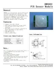
CIRC-11.:Larger Loads:..:Relays:.What We’re Doing:The final circuit is a bit of a test. We combine what we learnedabout using transistors in CIRC03 to control a relay. A relay isan electrically controlled mechanical switch. Inside the littleplastic box is an electromagnet that, when energized, causes aswitch to trip (often with a very satisfying clicking sound). You can buy relays that vary in sizefrom a quarter of the size of the one in this kit up to as big as a fridge, each capable ofswitching a certain amount of current. They are immensely fun because there is an element ofthe physical to them. While all the silicon we've played with to this point is fun sometimes youjust want to wire up a hundred switches to control something magnificent. Relays give you theability to dream it up then control it with your Arduino. Now to using todays technology tocontrol the past. (The 1N4001 diode is acting as a flyback diode for details on why its there visit: http://tinyurl.com/b559mx)The Circuit:Parts:CIRC-11Breadboard sheetx12 Pin Headerx4TransistorP2N2222AG (TO92)x1Relay(DPDT)x12.2k Ohm ResistorRed-Red-Redx1560 Ohm ResistorGreen-Blue-Brownx1Green LEDx1Red LEDx1Diode(1N4001)x1Schematic:resistor(2.2kohm)Arduinopin 2BaseTransistorP2N2222AGNONCcomCollectorcoilEmitterDiode(flyback)the transistor will haveP2N2222AG printed on it(some variations will havethe pin assignment reversed)+5 voltsgnd(ground) (-)The Internet.:download:.breadboard layout sheethttp://tinyurl.com/cxpvgq..:view:.assembling videohttp://tinyurl.com/chf7rx28
Code (no need to type everything in just)File > Sketchbook > Examples > Digital > Blink(example from the great arduino.cc site check it out for other great ideas)CIRC-11/** Blink** The basic Arduino example. Turns on an LED on for one second,* then off for one second, and so on... We use pin 13 because,* depending on your Arduino board, it has either a built-in LED* or a built-in resistor so that you need only an LED.** http://www.arduino.cc/en/Tutorial/Blink*/int ledPin = 2; // *********** CHANGE TO PIN 2 ************void setup()// run once, when the sketch starts{pinMode(ledPin, OUTPUT); // sets the digital pin as output}void loop(){digitalWrite(ledPin, HIGH);delay(1000);digitalWrite(ledPin, LOW);delay(1000);}// run over and over again// sets the LED on// waits for a second// sets the LED off// waits for a secondNot Working? (3 things to try)Nothing HappensNo Clicking SoundThe example code uses pin 13The transistor or coil portion ofand we have the relaythe circuit isn't quite working.connected to pin 2. Make sureCheck the transistor is pluggedyou made this change in thein the right way.code.Not Quite WorkingThe included relays aredesigned to be soldered ratherthan used in a breadboard. Assuch you may need to press itin to ensure it works. (and itmay pop out occasionally)Making it BetterControlling a MotorIn CIRC-03 we controlled a motor using a transistor.However if you want to control a larger motor a relay is agood option. To do this simply remove the red LED, andconnect the motor in its place (remember to bypass the560 Ohm resistor)Controlling Motor DirectionA bit of a complicated improvement to finish. To controlthe direction of spin of a DC motor we must be able toreverse the direction of current flow through it. To do thismanually we reverse the leads. To do it electrically werequire something called an h-bridge. This can be doneusing a DPDT relay to control the motor's direction, wireup the following circuit.DPDT RelayH-BridgeToyMotorresistor (2.2kohm)(red-red-red)NOIt looks complicated but can be accomplished using onlya few extra wires. Give it a try.NCcomCollectorcoilBase+5 voltsgnd(ground) (-)Arduinopin 2TransistorP2N2222AGEmitterDiode(flyback)More, More, More:More details, where to buy more parts, where to ask more questions.http://tinyurl.com/cfagqn29
(<strong>ARDX</strong>)arduino experimentation kitwww.oomlout.comThis work is licenced under the Creative Commons Attribution-ShareAlike 3.0 Unported License. To view a copy of this licence, visithttp://creativecommons.org/licenses/by-sa/3.0/ or send a letter toCreative Commons, 171 Second Street, Suite 300, San Francisco,California 94105, USA.