ARDX-experimenters-g.. - Oomlout
ARDX-experimenters-g.. - Oomlout
ARDX-experimenters-g.. - Oomlout

You also want an ePaper? Increase the reach of your titles
YUMPU automatically turns print PDFs into web optimized ePapers that Google loves.
(<strong>ARDX</strong>)<br />
arduino experimentation kit<br />
Arduino<br />
Experimenter’s<br />
Guide<br />
(<strong>ARDX</strong>)
A Few Words<br />
About this Kit<br />
The overall goal of this kit is fun. Beyond this, the aim is to get<br />
you comfortable using a wide range of electronic components<br />
through small, simple and easy circuits. The focus is to get<br />
each circuit working then giving you the tools to figure out why.<br />
If you encounter any problems, want to ask a question, or would<br />
like to know more about any part, extra help is only an e-mail away help@oomlout.com.<br />
About Open Source Hardware<br />
All of .:oomlout:.'s projects are open source. What does this mean It means everything<br />
involved in making this kit, be it this guide, 3D models, or code is available for free download.<br />
But it goes further, you're also free to reproduce and modify any of this material, then distribute<br />
it for yourself. The catch Quite simple; it is released under a Creative Commons (By - Share<br />
Alike) license. This means you must credit .:oomlout:. in your design and share your<br />
developments in a similar manner. Why We grew up learning and playing with open source<br />
software and the experience was good fun, we think it would be lovely if a similar experience<br />
was possible with physical things.<br />
(more details on the Creative Commons CC (By - Share Alike) License can be found at )<br />
( http://tinyurl.com/2dkzmd )<br />
About .: oomlout :.<br />
We’re a plucky little design company focusing on producing<br />
“delightfully fun open source products”<br />
To check out what we are up to<br />
http://www.oomlout.com<br />
About Problems<br />
We strive to deliver the highest level of quality in each and every thing we produce. If you ever<br />
find an ambiguous instruction, a missing piece, or would just like to ask a question, we’ll try our<br />
best to help out. You can reach us at:<br />
help@oomlout.com<br />
(we like hearing about problems it helps us improve future versions)<br />
Thanks For Choosing .:oomlout:.
.: Where to Find Everything :.<br />
TBCN<br />
table of contents<br />
Before We Start<br />
{ASEM} Assembling the Pieces 02<br />
{INST} Installing the Software 03<br />
{PROG} A Small Programming Primer 04<br />
{ELEC} A Small Electronics Primer 06<br />
The Circuits<br />
{CIRC01} Getting Started - (Blinking LED) 08<br />
{CIRC02} 8 LED Fun - (Multiple LEDs) 10<br />
{CIRC03} Spin Motor Spin - (Transistor and Motor) 12<br />
{CIRC04} A Single Servo - (Servos) 14<br />
{CIRC05} 8 More LEDs - (74HC595 Shift Register) 16<br />
{CIRC06} Music - (Piezo Elements) 18<br />
{CIRC07} Button Pressing - (Pushbuttons) 20<br />
{CIRC08} Twisting - (Potentiometers) 22<br />
{CIRC09} Light - (Photo Resistors) 24<br />
{CIRC10} Temperature - (TMP36 Temperature Sensor) 26<br />
{CIRC11} Larger Loads - (Relays) 28<br />
01
01 ASEM<br />
assembling the<br />
pieces<br />
.: Putting It Together :.<br />
Arduino Holder<br />
x1<br />
Breadboard<br />
x1<br />
Arduino<br />
x1<br />
3mm x 10mm bolt<br />
x2<br />
3mm nut<br />
x4<br />
02<br />
.: For an introduction to what an Arduino is visit :.<br />
.: http://tinyurl.com/9txjmh :.
.: Installing the IDE :.<br />
This is the program used to write programs for the Arduino (meta).<br />
It may seem a little daunting at first but once you have it installed<br />
and start playing around, its secrets will reveal themselves<br />
02 INST<br />
installing<br />
(software and hardware)<br />
Step 1: Download the software<br />
Goto<br />
http://arduino.cc/en/Main/Software<br />
And download the software for your operating system<br />
Windows XP<br />
Mac OSX<br />
Step 2: Unzip the Software<br />
Unzip<br />
arduino-00 -win.zip (<br />
Recommended Path<br />
c:\Program Files\<br />
- version #)<br />
Step 3: Shortcut Icon<br />
Open<br />
c:\program files\arduino-00 (<br />
Right Click<br />
Arduino.exe (send to>Desktop (create shortcut) )<br />
\ - version #)<br />
Step 2: Open The .dmg<br />
Open (mount)<br />
arduino-00-mac.dmg ( - version #)<br />
Step 3: Copy The Application<br />
Goto<br />
"Arduino" (in the devices section of finder)<br />
Move<br />
"Arduino" Application to the<br />
"Applications" folder<br />
Step 4: Plug In Your Arduino<br />
Plug your Arduino in:<br />
using the included USB cable, plug your Arduino board into a<br />
free USB port<br />
Wait for a box to pop up<br />
Step 4: Install Drivers<br />
Goto<br />
"Arduino" device<br />
Double Click & Install<br />
FTDI Drivers for Intel Macs ( _ _ ).pkg<br />
(FTDI Drivers for PPC Macs ( _ _ ).pkg<br />
Step 5: Add new Hardware<br />
Skip searching the internet<br />
(click the next box when prompted to do so)<br />
Install from a Specific destination<br />
(click “Install from a list or specific location (Advanced))<br />
Choose the Location<br />
c:\program files\arduino-00\drivers\FTDI USB Drivers\<br />
Finished<br />
Step 5: Plug In Your Arduino<br />
Plug your Arduino in:<br />
using the included USB cable, plug your Arduino board into a<br />
free USB port<br />
.: NOTE: :.<br />
.: Encountering problems :.<br />
.: Would like more details Using Linux :.<br />
.:http://tinyurl.com/r99d8u :.<br />
03
03 PROG<br />
programming<br />
primer<br />
.: A Small Programming Primer:.<br />
Arduino Programming in Brief<br />
The Arduino is programmed in the C language. This is a quick little primer targeted at people<br />
who have a little bit of programing experience and just need a briefing on the ideosyncrocies of<br />
C and the Arduino IDE. If you find the concepts a bit daunting, don't worry, you can start going<br />
through the circuits and pick up most of it along the way. For a more in depth intro the<br />
Arduino.cc website is a great resource (the foundations page http://tinyurl.com/954pun)<br />
Structure<br />
Each Arduino program<br />
(often called a sketch) has<br />
two required functions<br />
(also called routines).<br />
void setup(){ }<br />
All the code between the two<br />
curly brackets will be run once<br />
when your Arduino program<br />
first runs.<br />
void loop(){ }<br />
This function is run after setup<br />
has finished. After it has run<br />
once it will be run again, and<br />
again, until power is removed.<br />
Syntax<br />
One of the slightly<br />
frustrating elements of C is<br />
its formating requirements<br />
(this also makes it very<br />
powerful). If you remember<br />
the following you should be<br />
alright.<br />
// (single line comment)<br />
It is often useful to write notes<br />
to yourself as you go along<br />
about what each line of code<br />
does. To do this type two back<br />
slashes and everything until the<br />
end of the line will be ignored by<br />
your program.<br />
{ } (curly brackets)<br />
Used to define when a block of<br />
code starts and ends (used in<br />
functions as well as loops)<br />
/* */(multi line comment)<br />
If you have a lot to say you can<br />
span several lines as a<br />
comment. Everything between<br />
these two symbols will be<br />
ignored in your program.<br />
; (semicolon)<br />
Each line of code must be<br />
ended with a semicolon (a<br />
missing semicolon is often the<br />
reason for a programme<br />
refusing to compile)<br />
Variables<br />
A program is nothing more<br />
than instructions to move<br />
numbers around in an<br />
intelligent way. Variables are<br />
used to do the moving<br />
boolean (boolean)<br />
A simple True or False variable.<br />
Useful because it only uses one<br />
bit of RAM.<br />
04<br />
int (integer)<br />
The main workhorse, stores a<br />
number in 2 bytes (16 bits).<br />
Has no decimal places and will<br />
store a value between -32,768<br />
and 32,768.<br />
float (float)<br />
Used for floating point math<br />
(decimals). Takes 4 bytes (32<br />
bits) of RAM and has a range<br />
between -3.4028235E+38 and<br />
3.4028235E+38.<br />
long (long)<br />
Used when an integer is not<br />
large enough. Takes 4 bytes<br />
(32 bits) of RAM and has a<br />
range between -2,147,483,648<br />
and 2,147,483,648.<br />
char (character)<br />
Stores one character using the<br />
ASCII code (ie 'A' = 65). Uses<br />
one byte (8 bits) of RAM. The<br />
Arduino handles strings as an<br />
array of char’s
.:For a full programming reference visit:.<br />
http://tinyurl.com/882oxm<br />
03 PROG<br />
programming<br />
primer<br />
Maths Operators<br />
Operators used for<br />
manipulating numbers.<br />
(they work like simple<br />
maths)<br />
= (assignment) makes something equal to something else (eg. x =<br />
10 * 2 (x now equals 20))<br />
% (modulo) gives the remainder when one number is divided by<br />
another (ex. 12 % 10 (gives 2))<br />
+ (addition)<br />
- (subtraction)<br />
* (multiplication)<br />
/ (division)<br />
Comparison Operators<br />
Operators used for logical<br />
comparison<br />
== (equal to) (eg. 12 == 10 is FALSE or 12 == 12 is TRUE)<br />
!= (not equal to) (eg. 12 != 10 is TRUE or 12 != 12 is FALSE)<br />
< (less than) (eg. 12 < 10 is FALSE or 12 < 12 is FALSE or 12 < 14 is TRUE)<br />
> (greater than) (eg. 12 > 10 is TRUE or 12 > 12 is FALSE or 12 > 14 is<br />
FALSE)<br />
Control Structure<br />
Programs are reliant on<br />
controlling what runs<br />
next, here are the basic<br />
control elements (there<br />
are many more online)<br />
if(condition){ }<br />
else if( condition ){ }<br />
else { }<br />
This will execute the code between<br />
the curly brackets if the condition is<br />
true, and if not it will test the else<br />
if condition if that is also false the<br />
else code will execute.<br />
for(int i = 0; i <<br />
#repeats; i++){ }<br />
Used when you would like to<br />
repeat a chunk of code a number<br />
of times (can count up i++ or<br />
down i-- or use any variable)<br />
Digital<br />
pinMode(pin, mode);<br />
Used to set a pins mode, pin is<br />
the pin number you would like<br />
to address (0-19 (analog 0-5<br />
are 14-19). the mode can either<br />
be INPUT or OUTPUT.<br />
digitalWrite(pin, value);<br />
Once a pin is set as an OUTPUT,<br />
it can be set either HIGH (pulled<br />
to +5 volts) or LOW (pulled to<br />
ground).<br />
int digitalRead(pin);<br />
Once a pin is set as an INPUT<br />
you can use this to return<br />
whether it is HIGH (pulled to<br />
+5 volts) or LOW (pulled to<br />
ground).<br />
Analog<br />
The Arduino is a digital<br />
machine but it has the ability to<br />
operate in the analog realm<br />
(through tricks). Here's how to<br />
deal with things that aren't<br />
digital.<br />
int analogWrite(pin,<br />
value);<br />
Some of the Arduino's pins support<br />
pulse width modulation (3, 5, 6, 9, 10,<br />
11). This turns the pin on and off very<br />
quickly making it act like an analog<br />
output. The value is any number<br />
between 0 (0% duty cycle ~0v) and 255<br />
(100% duty cycle ~5 volts).<br />
int analogRead(pin);<br />
When the analog input pins are set<br />
to input you can read their voltage.<br />
A value between 0 (for 0<br />
volts) and 1024 (for 5<br />
volts) will be<br />
returned<br />
05
04 ELEC<br />
electronics<br />
primer<br />
.: A Small Electronics Primer:.<br />
Electronics in Brief<br />
No previous electronic experience is required to have fun with this kit. Here are a few details<br />
about each component to make identifying, and perhaps understanding them, a bit easier. If at<br />
any point you are worried about how a component is used or why its not working the internet<br />
offers a treasure trove of advice, or we can be contacted at help@oomlout.com<br />
Component Details<br />
LED<br />
(Light Emitting Diode)<br />
What it Does:<br />
No. of Leads:<br />
Emits light when a small current is passed 2 (one longer this one connects to positive)<br />
through it. (only in one direction)<br />
Things to watch out for:<br />
Identifying: - Will only work in one direction<br />
Looks like a mini light bulb. - Requires a current limiting resistor<br />
More Details on Wikipedia:<br />
http://tinyurl.com/zhpyv<br />
Diode What it Does: No. of Leads:<br />
The electronic equivalent of a one way 2<br />
valve. Allowing current to flow in one Things to watch out for:<br />
direction but not the other. - Will only work in one direction (current will<br />
Identifying:<br />
flow if end with the line is connected to ground)<br />
Usually a cylinder with wires extending from More Details on Wikipedia:<br />
either end. (and an off center line indicating polarity)<br />
http://tinyurl.com/ysz57b<br />
Resistors<br />
What it Does: No. of Leads:<br />
Restricts the amount of current that can flow 2<br />
through a circuit.<br />
Things to watch out for:<br />
Identifying: - Easy to grab the wrong value (double check<br />
Cylinder with wires extending from either<br />
the colors before using)<br />
end. The resistance value is displayed using More Details on Wikipedia:<br />
a color coding system (for details see next http://tinyurl.com/cmeqw5<br />
page)<br />
Transistor What it Does: No. of Leads:<br />
Uses a small current to switch or amplify a 3 (Base, Collector, Emitter)<br />
much larger current.<br />
Things to watch out for:<br />
Identifying: - Plugging in the right way round.(also a<br />
Comes in many different packages but you<br />
current limiting resistor is often needed on the base pin)<br />
can read the part number off the package. More Details on Wikipedia:<br />
(P2N2222AG in this kit and find a datasheet online) http://tinyurl.com/eazkn<br />
Hobby Servo<br />
What it Does:<br />
No. of Leads:<br />
Takes a timed pulse and converts it into an 3<br />
angular position of the output shaft.<br />
Things to watch out for:<br />
Identifying: - The plug is not polarized so make sure it<br />
A plastic box with 3 wires coming out one is plugged in the right way.<br />
side and a shaft with a plastic horn out the More Details:<br />
top. http://tinyurl.com/4zo4he<br />
DC Motor What it Does: No. of Leads:<br />
06<br />
Spins when a current is passed through it. 2<br />
Identifying:<br />
Things to watch out for:<br />
This one is easy, it looks like a motor. Usually - Using a transistor or relay that is rated for<br />
a cylinder with a shaft coming out of one the size of motor you're using.<br />
end<br />
More Details on Wikipedia:<br />
http://tinyurl.com/d826yh
Component Details (cont.)<br />
Piezo Element<br />
What it Does:<br />
No. of Leads:<br />
A pulse of current will cause it to click a 2<br />
stream of pulses will cause it to emit a tone. Things to watch out for:<br />
Identifying: - Difficult to misuse.<br />
In this kit it comes in a little black barrel, but More Details:<br />
sometimes they are just a gold disc. http://tinyurl.com/38crmu<br />
04 ELEC<br />
electronics<br />
primer<br />
IC (Integrated Circuit)<br />
What it Does:<br />
Packages any range of complicated<br />
electronics inside, an easy to use form factor<br />
Identifying:<br />
The part ID is written on the outside of the<br />
package. (this sometimes requires a lot of<br />
light or a magnifying glass to read)<br />
No. of Leads:<br />
2 - 100s (in this kit there is one with 3 (TMP36) and<br />
one with 16 (74HC595)<br />
Things to watch out for:<br />
- Proper orientation.(look for marks showing pin 1)<br />
More Details:<br />
http://tinyurl.com/87k4d<br />
Pushbutton What it Does:<br />
No. of Leads:<br />
Completes a circuit when it is pressed 4<br />
Identifying:<br />
Things to watch out for:<br />
A little square with leads out the bottom and - these are almost square so can be<br />
a button on the top.<br />
inserted 90 degrees off angle.<br />
More Details:<br />
http://tinyurl.com/cmts7d<br />
Potentiometer<br />
Photo Resistor<br />
What it Does:<br />
No. of Leads:<br />
Produces a variable resistance dependant on 3<br />
the angular position of the shaft.<br />
Things to watch out for:<br />
Identifying: - Accidentally buying logarithmic scale.<br />
They can be packaged in many different More Details:<br />
form factors, look for a dial to identify. http://tinyurl.com/28pbhd<br />
What it Does:<br />
No. of Leads:<br />
Produces a variable resistance dependant on 2<br />
the amount of incident light.<br />
Things to watch out for:<br />
Identifying: - Remember it needs to be in a voltage<br />
Usually a little disk with a clear top and a divider before it provides a useful input.<br />
curvy line underneath.<br />
More Details:<br />
http://tinyurl.com/c2wdkw<br />
Resistor Color Code<br />
Examples:<br />
:<br />
green-blue-brown - 560 ohms<br />
red-red-red - 2 200 ohms (2.2k)<br />
first digit<br />
second digit<br />
# of zeros<br />
tolerance<br />
0 - Black 5 - Green 20% - none<br />
1 - Brown 6 - Blue 10% - silver<br />
2 - Red 7 - Purple 5% - gold<br />
3 - Orange 8 - Grey<br />
4 - Yellow 9 - White<br />
Lead Clipping<br />
Some components in this kit come with very long wire<br />
leads. To make them more compatible with a breadboard<br />
a couple of changes are required.<br />
LEDs:<br />
Clip the leads so the long lead is ~7mm long and the<br />
short one is ~5mm<br />
Resistors:<br />
Bend the leads down so they are 90 degrees to the<br />
cylinder. Then snip them so they are ~6mm long.<br />
Other Components:<br />
Other components may need clipping<br />
use your discretion when doing so.<br />
07
CIRC-01<br />
.:Getting Started:.<br />
.:(Blinking LED):.<br />
What We’re Doing:<br />
LEDs (light emitting diodes) are used in all sorts of clever<br />
things which is why we have included them in this kit. We will<br />
start off with something very simple, turning one on and off,<br />
repeatedly, producing a pleasant blinking effect. To get started<br />
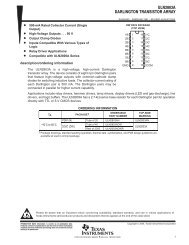
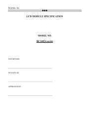
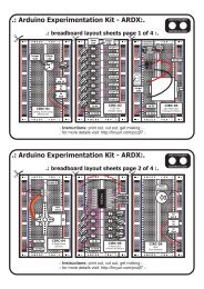
grab the parts listed below, pin the layout sheet to your breadboard and then plug everything in.<br />
Once the circuit is assembled you'll need to upload the program. To do this plug the Arduino<br />
board into your USB port. Then select the proper port in Tools > Serial Port > (the comm<br />
port of your Arduino). Next upload the program by going to File > Upload to I/O Board<br />
(ctrl+U). Finally bask in the glory and possibility that controlling lights offers.<br />
If you are having trouble uploading, a full trouble shooting guide can be found here: http://tinyurl.com/89s2po<br />
The Circuit:<br />
Parts:<br />
CIRC-01<br />
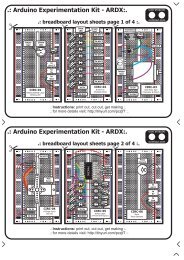
Breadboard sheet<br />
x1<br />
2 Pin Header<br />
x4<br />
10mm LED<br />
x1<br />
Wire<br />
560 Ohm Resistor<br />
Green-Blue-Brown<br />
x1<br />
Schematic:<br />
Arduino<br />
pin 13<br />
+<br />
longer lead<br />
LED<br />
(light emitting diode)<br />
resistor (560ohm)<br />
(green-blue-brown)<br />
gnd<br />
(ground) (-)<br />
The Internet<br />
.:download:.<br />
breadboard layout sheet<br />
http://tinyurl.com/qukhvc<br />
.:view:.<br />
assembling video<br />
http://tinyurl.com/cwhx27<br />
08
Code (no need to type everything in just)<br />
File > Examples > Digital > Blink<br />
(example from the great arduino.cc site check it out for other ideas)<br />
CIRC-01<br />
/* Blink<br />
* Turns on an LED on for one second, then off for one second,<br />
* repeatedly.<br />
* Created 1 June 2005 By David Cuartielles<br />
* http://arduino.cc/en/Tutorial/Blink<br />
* based on an orginal by H. Barragan for the Wiring i/o board<br />
*/<br />
int ledPin = 13; // LED connected to digital pin 13<br />
// The setup() method runs once, when the sketch starts<br />
void setup() { // initialize the digital pin as an output:<br />
pinMode(ledPin, OUTPUT); }<br />
// the loop() method runs over and over again,<br />
// as long as the Arduino has power<br />
void loop() {<br />
digitalWrite(ledPin, HIGH); // set the LED on<br />
delay(1000);<br />
// wait for a second<br />
digitalWrite(ledPin, LOW); // set the LED off<br />
delay(1000);<br />
// wait for a second<br />
}<br />
Not Working (3 things to try)<br />
LED Not Lighting Up<br />
LEDs will only work in one<br />
direction.<br />
Try taking it out and twisting it<br />
180 degrees.<br />
(no need to worry, installing it<br />
backwards does no permanent<br />
harm)<br />
Program Not Uploading<br />
This happens sometimes,<br />
the most likely cause is a<br />
confused serial port, you<br />
can change this in<br />
tools>serial port><br />
Still No Success<br />
A broken circuit is no fun, send<br />
us an e-mail and we will get<br />
back to you as soon as we can.<br />
help@oomlout.com<br />
Making it Better<br />
Changing the pin:<br />
The LED is connected to pin 13 but we can use any of<br />
the Arduino’s pins. To change it take the wire plugged<br />
into pin 13 and move it to a pin of your choice (from 0-<br />
Control the Brightness:<br />
Along with digital (on/off) control the Arduino can control<br />
some pins in an analog (brightness) fashion. (more details on<br />
this in later circuits). To play around with it.<br />
13) (you can also use analog 0-5 analog 0 is 14...) Change the LED to pin 9: (also change the wire)<br />
Then in the code change the line:<br />
ledPin = 13; -> int ledPin = 9;<br />
int ledPin = 13; -> int ledPin = newpin; Replace the code inside the { }'s of loop() with this:<br />
Then upload the sketch: (ctrl-u)<br />
analogWrite(ledPin, new number);<br />
Change the Blink Time: (new number) = any number between 0 and 255.<br />
Unhappy with one second on one second off<br />
0 = off, 255 = on, in between = different brightness<br />
In the code change the lines:<br />
digitalWrite(ledPin, HIGH);<br />
delay(time on); //(seconds * 1000)<br />
digitalWrite(ledPin, LOW);<br />
delay(time off); //(seconds * 1000)<br />
Fading:<br />
We will use another included example program. To open go to.<br />
File > Examples > Analog > Fading<br />
Then upload to your board and watch as the LED fades in and<br />
then out.<br />
More, More, More:<br />
More details, where to buy more parts, where to ask more questions.<br />
http://tinyurl.com/cmn5nh<br />
09
CIRC-02<br />
.:8 LED Fun:.<br />
.:Multiple LED’s:.<br />
What We’re Doing:<br />
We have caused one LED to blink, now its time to up the<br />
stakes. Lets connect eight. We'll also have an opportunity to<br />
stretch the Arduino a bit by creating various lighting sequences.<br />
This circuit is also a nice setup to experiment with writing your<br />
own programs and getting a feel for how the Arduino works.<br />
Along with controlling the LEDs we start looking into a few simple programming methods to<br />
keep your programs small.<br />
for() loops - used when you want to run a piece of code several times.<br />
arrays[] - used to make managing variables easier (its a group of variables)<br />
The Circuit:<br />
Parts:<br />
CIRC-02<br />
Breadboard sheet<br />
x1<br />
2 Pin Header<br />
x4<br />
5mm Green LED<br />
x8<br />
Wire<br />
560 Ohm Resistor<br />
Green-Blue-Brown<br />
x8<br />
Schematic:<br />
pin 2 pin 3 pin 4 pin 5<br />
LED<br />
gnd<br />
resistor<br />
560ohm<br />
pin 6 pin 7 pin 8 pin 9<br />
LED<br />
gnd<br />
resistor<br />
560ohm<br />
The Internet<br />
.:download:.<br />
breadboard layout sheet<br />
http://tinyurl.com/d4gmov<br />
.:view:.<br />
assembling video<br />
http://tinyurl.com/coafoh<br />
10
Code (no need to type everything in just)<br />
Download the Code from ( http://tinyurl.com/dkpxbn )<br />
(and then copy the text and paste it into an empty Arduino Sketch)<br />
CIRC-02<br />
//LED Pin Variables<br />
* will then turn them off<br />
int ledPins[] = {2,3,4,5,6,7,8,9};<br />
//An array to hold the<br />
void oneAfterAnotherNoLoop(){<br />
//pin each LED is connected to int delayTime = 100;<br />
/ / i . e . L E D # 0 i s c o n n e c t e d t o p i n 2 / / t h e t i m e ( i n m i l l i s e c o n d s ) t o p a u s e<br />
//between LEDs<br />
void setup() digitalWrite(ledPins[0], HIGH); //Turns on LED #0<br />
{ //(connected to pin 2)<br />
for(int i = 0; i < 8; i++){ delay(delayTime); //waits delayTime milliseconds<br />
//this is a loop and will repeat eight times ...<br />
pinMode(ledPins[i],OUTPUT); ...<br />
//we use this to set LED pins to output digitalWrite(ledPins[7], HIGH); //Turns on LED #7<br />
} //(connected to pin 9)<br />
} delay(delayTime); //waits delayTime milliseconds<br />
//Turns Each LED Off<br />
void loop() // run over and over again digitalWrite(ledPins[7], LOW); //Turns off LED #7<br />
{ delay(delayTime); //waits delayTime milliseconds<br />
oneAfterAnotherNoLoop(); ...<br />
//this will turn on each LED one by<br />
//one then turn each oneoff<br />
-----more code in the downloadable version------<br />
//oneAfterAnotherLoop();<br />
//this does the same as onAfterAnotherNoLoop<br />
//but with much less typing<br />
//oneOnAtATime();<br />
//inAndOut();<br />
}<br />
/*<br />
* oneAfterAnotherNoLoop() - Will light one then<br />
* delay for delayTime then light the next LED it<br />
Not Working (3 things to try)<br />
Some LEDs Fail to Light<br />
It is easy to insert an LED<br />
backwards. Check the LEDs<br />
that aren't working and ensure<br />
they the right way around.<br />
Operating out of sequence<br />
With eight wires it's easy to cross<br />
a couple. Double check that the<br />
first LED is plugged into pin 2 and<br />
each pin there after.<br />
Starting Afresh<br />
Its easy to accidentally<br />
misplace a wire without<br />
noticing. Pulling everything out<br />
and starting with a fresh slate<br />
is often easier than trying to<br />
track down the problem.<br />
Making it Better<br />
Switching to Loops:<br />
in the loop() function there are 4 lines. The last<br />
three all start with a '//' this means the line is<br />
treated as a comment (not run). To switch the<br />
program to use loops change the void loop()<br />
code to:<br />
//oneAfterAnotherNoLoop();<br />
oneAfterAnotherLoop();<br />
//oneOnAtATime();<br />
//inAndOut();<br />
Upload the program, and notice that nothing has<br />
changed. You can take a look at the two<br />
functions, each does the same thing, but use<br />
different approaches (hint the second one uses a<br />
for loop)<br />
Extra Animations:<br />
Tired of this animation Then try the other two<br />
sample animations. Uncomment their lines and<br />
upload the program to your board and enjoy the new<br />
light animations. (delete the slashes in front of row 3 and then 4)<br />
Testing out your own Animations:<br />
Jump into the included code and start changing<br />
things. The main point is to turn an LED on use<br />
digitalWrite(pinNumber, HIGH); then to<br />
turn it off use digitalWrite(pinNumber,<br />
LOW); . Type away, regardless of what you change<br />
you won't break anything.<br />
More, More, More:<br />
More details, where to buy more parts, where to ask more questions.<br />
http://tinyurl.com/d2hrud<br />
11
CIRC-03<br />
.:Spin Motor Spin:.<br />
.:Transistor & Motor:.<br />
What We’re Doing:<br />
The Arduino's pins are great for directly controlling small electric<br />
items like LEDs. However, when dealing with larger items (like a<br />
toy motor or washing machine), an external transistor is required.<br />
A transistor is incredibly useful. It switches a lot of current using a<br />
much smaller current. A transistor has 3 pins. For a negative type<br />
(NPN) transistor you connect your load to collector and the emitter to ground. Then when a small<br />
current flows from base to the emitter a current will flow through the transistor and your motor will<br />
spin (this happens when we set our Arduino pin HIGH). There are literally thousands of different<br />
types of transistors, allowing every situation to be perfectly matched. We have chosen a P2N2222AG<br />
a rather common general purpose transistor. The important factors in our case are that its maximum<br />
voltage (40 v) and its maximum current (600 milliamp) are both high enough for our toy motor (full<br />
details can be found on its datasheet http://tinyurl.com/o2cm93 )<br />
note: the transistor we use has a in order Base Collector Emitter pinout (differing from some other popular transistors)<br />
(The 1N4001 diode is acting as a flyback diode for details on why its there visit: http://tinyurl.com/b559mx)<br />
The Circuit:<br />
Parts:<br />
CIRC-03<br />
Breadboard sheet<br />
x1<br />
Toy Motor<br />
x1<br />
2 Pin Header<br />
x4<br />
Diode<br />
(1N4001)<br />
x1<br />
Transistor<br />
P2N2222AG (TO92)<br />
x1<br />
2.2k Ohm Resistor<br />
Red-Red-Red<br />
x1<br />
Wire<br />
Schematic:<br />
Arduino<br />
pin 9<br />
the transistor will have<br />
P2N2222AG printed on it<br />
(some variations will have<br />
the pin assignment reversed)<br />
resistor<br />
(2.2kohm)<br />
Base<br />
Collector<br />
Diode<br />
Motor<br />
Transistor<br />
P2N2222AG<br />
Emitter<br />
gnd<br />
(ground) (-)<br />
+5 volts<br />
The Internet<br />
.:download:.<br />
breadboard layout sheet<br />
http://tinyurl.com/d6jv63<br />
.:view:.<br />
assembling video<br />
http://tinyurl.com/djapjg<br />
12<br />
.:NOTE: if your arduino is resetting you need to install the optional capacitor:.
Code (no need to type everything in just)<br />
Download the Code from ( http://tinyurl.com/dagyrb )<br />
(then simply copy the text and paste it into an empty Arduino Sketch)<br />
int motorPin = 9; //pin the motor is connected to<br />
CIRC-03<br />
void setup() //runs once<br />
void motorOnThenOffWithSpeed(){<br />
{ int onSpeed = 200;// a number between<br />
pinMode(motorPin, OUTPUT);<br />
//0 (stopped) and 255 (full speed)<br />
} int onTime = 2500;<br />
int offSpeed = 50;// a number between<br />
void loop() // run over and over again //0 (stopped) and 255 (full speed)<br />
{ int offTime = 1000;<br />
motorOnThenOff(); analogWrite(motorPin, onSpeed);<br />
//motorOnThenOffWithSpeed(); // turns the motor On<br />
//motorAcceleration(); delay(onTime); // waits for onTime milliseconds<br />
} analogWrite(motorPin, offSpeed);<br />
// turns the motor Off<br />
/* delay(offTime); // waits for offTime milliseconds<br />
* motorOnThenOff() - turns motor on then off }<br />
used for<br />
void motorAcceleration(){<br />
* the blinking LED)<br />
int delayTime = 50; //time between each speed step<br />
*/<br />
for(int i = 0; i < 256; i++){<br />
void motorOnThenOff(){<br />
//goes through each speed from 0 to 255<br />
int onTime = 2500; //on time<br />
analogWrite(motorPin, i); //sets the new speed<br />
int offTime = 1000; //off time<br />
delay(delayTime);// waits for delayTime milliseconds<br />
digitalWrite(motorPin, HIGH);<br />
}<br />
// turns the motor On<br />
for(int i = 255; i >= 0; i--){<br />
delay(onTime); // waits for onTime milliseconds<br />
//goes through each speed from 255 to 0<br />
digitalWrite(motorPin, LOW);<br />
analogWrite(motorPin, i); //sets the new speed<br />
// turns the motor Off<br />
delay(delayTime);//waits for delayTime milliseconds<br />
delay(offTime);// waits for offTime milliseconds }<br />
}<br />
}<br />
* (notice this code is identical to the code we<br />
Not Working (3 things to try)<br />
Motor Not Spinning<br />
if you sourced your own<br />
transistor, double check with<br />
the data sheet that the pinout<br />
is compatible with a P2N2222A<br />
(many are reversed)<br />
Still No Luck<br />
if you sourced your own motor,<br />
double check that it will work<br />
with 5 volts and that it does not<br />
draw too much power.<br />
Still Not Working<br />
Sometimes the Arduino board<br />
will disconnect from the<br />
computer. Try un-plugging and<br />
then re-plugging it into your<br />
USB port.<br />
Making it Better<br />
Controlling Speed:<br />
We played with the Arduino's ability to control the<br />
brightness of an LED earlier now we will use the same<br />
feature to control the speed of our motor. The Arduino<br />
does this using something called Pulse Width<br />
Modulation (PWM). This relies on the Arduino's ability to<br />
operate really really fast. Rather than directly controlling<br />
the voltage coming from the pin the Arduino will switch<br />
the pin on and off very quickly. In the computer world<br />
this is going from 0 to 5 volts many times a second, but<br />
in the human world we see it as a voltage. For example<br />
if the Arduino is PWM'ing at 50% we see the light<br />
dimmed 50% because our eyes are not quick enough to<br />
see it flashing on and off. The same feature works with<br />
transistors. Don't believe me Try it out.<br />
In the loop() section change it to this<br />
// motorOnThenOff();<br />
motorOnThenOffWithSpeed();<br />
//motorAcceleration();<br />
Then upload the programme. You can change the speeds by<br />
changing the variables onSpeed and offSpeed<br />
Accelerating and decelerating:<br />
Why stop at two speeds, why not accelerate and decelerate<br />
the motor. To do this simply change the loop() code to read<br />
// motorOnThenOff();<br />
// motorOnThenOffWithSpeed();<br />
motorAcceleration();<br />
Then upload the program and watch as your motor slowly<br />
accelerates up to full speed then slows down again. If you<br />
would like to change the speed of acceleration change the<br />
variable delayTime (larger means a longer acceleration time)<br />
More, More, More:<br />
More details, where to buy more parts, where to ask more questions.<br />
http://tinyurl.com/d4wht7<br />
13
CIRC-04<br />
.:A Single Servo:.<br />
.:Servos:.<br />
What We’re Doing:<br />
Spinning a motor is good fun but when it comes to projects<br />
where motion control is required they tend to leave us wanting<br />
more. The answer Hobby servos. They are mass produced,<br />
widely available and cost anything from a couple of dollars to<br />
hundreds. Inside is a small gearbox (to make the movement more powerful) and some<br />
electronics (to make it easier to control). A standard servo is positionable from 0 to 180<br />
degrees. Positioning is controlled through a timed pulse, between 1.25 milliseconds (0 degrees)<br />
and 1.75 milliseconds (180 degrees) (1.5 milliseconds for 90 degrees). Timing varies between<br />
manufacturer. If the pulse is sent every 25-50 milliseconds the servo will run smoothly. One of<br />
the great features of the Arduino is it has a software library that allows you to control two<br />
servos (connected to pin 9 or 10) using a single line of code.<br />
The Circuit:<br />
Parts:<br />
CIRC-04<br />
Breadboard sheet<br />
x1<br />
2 Pin Header<br />
x4<br />
3 Pin Header<br />
x1<br />
Wire<br />
Mini Servo<br />
x1<br />
Schematic:<br />
Arduino<br />
pin 9<br />
Mini Servo<br />
signal<br />
(orange)<br />
gnd<br />
(black/<br />
brown)<br />
+5v<br />
(red)<br />
gnd<br />
(ground) (-)<br />
+5 volts<br />
(5V)<br />
The Internet<br />
.:download:.<br />
breadboard layout sheet<br />
http://tinyurl.com/db5fcm<br />
.:view:.<br />
assembling video<br />
http://tinyurl.com/d52954<br />
14
Code (no need to type everything in just)<br />
File > Examples > Servo > Sweep<br />
(example from the great arduino.cc site check it out for other great ideas)<br />
CIRC-04<br />
// Sweep<br />
// by BARRAGAN <br />
#include <br />
Servo myservo; // create servo object to control a servo<br />
int pos = 0; // variable to store the servo position<br />
void setup() {<br />
myservo.attach(9); // attaches the servo on pin 9 to the servo object<br />
}<br />
void loop() {<br />
for(pos = 0; pos < 180; pos += 1) // goes from 0 degrees to 180 degrees<br />
{ // in steps of 1 degree<br />
myservo.write(pos);<br />
// tell servo to go to position in variable 'pos'<br />
delay(15);<br />
// waits 15ms for the servo to reach the position<br />
}<br />
for(pos = 180; pos>=1; pos-=1) // goes from 180 degrees to 0 degrees<br />
{<br />
myservo.write(pos);<br />
// tell servo to go to position in variable 'pos'<br />
delay(15);<br />
// waits 15ms for the servo to reach the position<br />
}<br />
}<br />
Not Working (3 things to try)<br />
Servo Not Twisting<br />
Even with colored wires it is still<br />
shockingly easy to plug a servo<br />
in backwards. This might be the<br />
case.<br />
Still not Working<br />
A mistake we made a time or<br />
two was simply forgetting to<br />
connect the power (red and<br />
brown wires) to +5 volts and<br />
ground.<br />
Fits and Starts<br />
If the servo begins moving then<br />
twitches, and there's a flashing<br />
light on your Arduino board, the<br />
power supply you are using is<br />
not quite up to the challenge.<br />
Using a 9V battery instead<br />
should solve this problem.<br />
Making it Better<br />
Potentiometer Control:<br />
void loop() {<br />
We have yet to experiment with inputs but if you would like to int pulseTime = 2100; //(the number of microseconds<br />
//to pause for (1500 90 degrees<br />
read ahead, there is an example program File > Examples ><br />
// 900 0 degrees 2100 180 degrees)<br />
Servo > Knob. This uses a potentiometer (CIRC08) to control digitalWrite(servoPin, HIGH);<br />
delayMicroseconds(pulseTime);<br />
the servo. You can find instructions online here:<br />
digitalWrite(servoPin, LOW);<br />
delay(25);<br />
http://tinyurl.com/dymsk2 }<br />
Self Timing:<br />
While it is easy to control a servo using the Arduino's included<br />
library sometimes it is fun to figure out how to program<br />
something yourself. Try it. We're controlling the pulse directly<br />
so you could use this method to control servos on any of the<br />
Arduino's 20 available pins (you need to highly optimize this<br />
code before doing that).<br />
int servoPin = 9;<br />
void setup(){<br />
pinMode(servoPin,OUTPUT);<br />
}<br />
Great Ideas:<br />
Servos can be used to do all sorts of great things, here are a few of<br />
our favorites.<br />
Xmas Hit Counter<br />
http://tinyurl.com/37djhq<br />
Open Source Robotic Arm (uses a servo controller as well as the Arduino)<br />
http://tinyurl.com/ckm3wd<br />
Servo Walker<br />
http://tinyurl.com/da5jfe<br />
More, More, More:<br />
More details, where to buy more parts, where to ask more questions.<br />
http://tinyurl.com/djwlop<br />
15
CIRC-05<br />
.:8 More LEDs:.<br />
.:74HC595 Shift Register:.<br />
What We’re Doing:<br />
Time to start playing with chips. Or integrated circuits (ICs) as they like to be<br />
called. The external packaging of a chip can be very deceptive for example the<br />
chip on the Arduino board (a micro controller) and the one we will use in this<br />
circuit (a shift register) look very similar but are in fact rather different, for<br />
example the price of the Atmega chip on the arduino board is a few dollars while the<br />
74hc595 is a couple dozen cents. It's a good introductory chip, and once your comfortable playing around with it and its<br />
datasheet (available online http://tinyurl.com/pr42xe ) the world of chips will be your oyster. The shift register (also called<br />
a serial to parallel converter), will give you an additional 8 outputs (to control LEDs and the like) using only three arduino<br />
pins. They can also be linked together to give you a nearly unlimited number of outputs using the same four pins. To use<br />
it you “clock in” the data and then latch lock it in (latch it). To do this you set the data pin to either HIGH or LOW, pulse<br />
the clock, then set the data pin again and pulse the clock repeating until you have shifted out 8 bits of data. Then you<br />
pulse the latch and the 8 bits are transferred to the shift registers pins. It sounds complicated but is really simple once<br />
you get the hang of it.<br />
(for a more in depth look at how a shift register works visit: http://tinyurl.com/56uvv7 )<br />
The Circuit:<br />
Parts:<br />
CIRC-05<br />
Breadboard sheet<br />
x1<br />
Red LED<br />
x8<br />
2 Pin Header<br />
x4<br />
560 Ohm Resistor<br />
Green-Blue-Brown<br />
x8<br />
Shift Register<br />
74HC595<br />
x1<br />
Wire<br />
pin<br />
4<br />
Schematic:<br />
+5 volts<br />
pin<br />
3<br />
pin<br />
2<br />
74HC595<br />
+5V<br />
data<br />
clock<br />
latch<br />
gnd<br />
0<br />
1<br />
2<br />
3<br />
4<br />
5<br />
6<br />
7<br />
LED<br />
resistor<br />
(560ohm)<br />
gnd<br />
(ground) (-)<br />
There is a half moon<br />
cutout, this goes at the top<br />
The Internet<br />
.:download:.<br />
breadboard layout sheet<br />
http://tinyurl.com/d8xepz.<br />
.:view:.<br />
assembling video<br />
http://tinyurl.com/c2enkv<br />
16
Code (no need to type everything in just)<br />
Download the Code from ( http://tinyurl.com/cv4fjt )<br />
(copy the text and paste it into an empty Arduino Sketch)<br />
//Pin Definitions<br />
//The 74HC595 uses a protocol called SPI<br />
//Which has three pins<br />
int data = 2;<br />
int clock = 3;<br />
int latch = 4;<br />
digitalWrite(latch, LOW);<br />
CIRC-05<br />
//Pulls the chips latch low<br />
shiftOut(data, clock, MSBFIRST, value);<br />
void setup() //runs once //Shifts out 8 bits to the shift register<br />
{<br />
pinMode(data, OUTPUT);<br />
pinMode(clock, OUTPUT);<br />
digitalWrite(latch, HIGH);<br />
pinMode(latch, OUTPUT); } //Pulls the latch high displaying the data<br />
}<br />
void loop() // run over and over again<br />
{ ---------- More Code Online ----------<br />
int delayTime = 100;<br />
//delay between LED updates<br />
for(int i = 0; i < 256; i++){<br />
updateLEDs(i);<br />
delay(delayTime); }<br />
}<br />
/*<br />
* updateLEDs() - sends the LED states set<br />
* in value to the 74HC595 sequence<br />
*/<br />
void updateLEDs(int value){<br />
Not Working (3 things to try)<br />
The Arduino’s Power<br />
LED goes out<br />
This happened to us a couple<br />
of times, it happens when the<br />
chip is inserted backwards. If<br />
you fix it quickly nothing will<br />
break.<br />
Not Quite Working<br />
Sorry to sound like a broken<br />
record but it is probably<br />
something as simple as a<br />
crossed wire.<br />
Frustration<br />
Shoot us an e-mail, this circuit<br />
is both simple and complex at<br />
the same time. We want to<br />
hear about problems you have<br />
so we can address them in<br />
future editions.<br />
help@oomlout.com<br />
Making it Better<br />
Doing it the hard way:<br />
An Arduino makes rather complex actions very easy, shifting out data<br />
is one of these cases. However one of the nice features of an<br />
Arduino is you can make things as easy or difficult as you like. Lets<br />
try an example of this. In your loop switch the line.<br />
updateLEDs(i) -> updateLEDsLong(i);<br />
Upload the program and notice nothing has changed. If you look at<br />
the code you can see how we are communicating with the chip one<br />
bit at a time. (for more details http://tinyurl.com/3augzd )<br />
Controlling Individual LEDs:<br />
Time to start controlling the LEDs in a similar method as we did in<br />
CIRC02. As the eight LED states are stored in one byte (an 8 bit<br />
value) for details on how this works try http://tinyurl.com/6vz53. An<br />
Arduino is very good at manipulating bits and there are an entire set<br />
of operators that help us out. Details on bitwise maths (<br />
http://tinyurl.com/br8dd )<br />
Our implementation.<br />
Replace the loop() code with<br />
int delayTime = 100; //the number of<br />
milliseconds to delay<br />
//between LED updates<br />
for(int i = 0; i < 8; i++){<br />
changeLED(i,ON);<br />
delay(delayTime);<br />
}<br />
for(int i = 0; i < 8; i++){<br />
changeLED(i,OFF);<br />
delay(delayTime);<br />
}<br />
And upload this will cause the lights to light up one after another and then<br />
off in a similar manner. Check the code and wikipedia to see how it works,<br />
or shoot us an e-mail if you have questions.<br />
More Animations:<br />
Now things get more interesting. If you look back to the code from CIRC02<br />
(8 LED Fun) you see we change the LEDs using digitalWrite(led, state), this<br />
is the same format as the routine we wrote changeLED(led, state). You can<br />
use the animations you wrote for CIRC02 by copying the code into this<br />
sketch and changing all the digitalWrite()'s to changeLED()'s. Powerful<br />
Very. (you'll also need to change a few other things but follow the compile<br />
errors and it works itself out)<br />
More, More, More:<br />
More details, where to buy more parts, where to ask more questions.<br />
http://tinyurl.com/dkjno3<br />
17
CIRC-06<br />
.:Music:.<br />
.:Piezo Elements:.<br />
What We’re Doing:<br />
To this point we have controlled light, motion, and<br />
electrons, Lets tackle sound next. But sound is an<br />
analog phenomena, how will our digital Arduino cope<br />
We will once again rely on its incredible speed which will let<br />
it mimic analog behavior. To do this, we will attach a piezo element to one of the<br />
Arduino's digital pins. A piezo element makes a clicking sound each time it is pulsed<br />
with current. If we pulse it at the right frequency (for example 440 times a second<br />
to make the note middle A) these clicks will run together to produce notes. Lets get<br />
to experimenting with it and get your Arduino playing 'Twinkle Twinkle Little Star'.<br />
The Circuit:<br />
Parts:<br />
CIRC-06<br />
Breadboard sheet<br />
x1<br />
2 Pin Header<br />
x4<br />
Piezo Element<br />
x1<br />
Wire<br />
Schematic:<br />
Arduino<br />
pin 9<br />
Piezo<br />
Element<br />
gnd<br />
(ground) (-)<br />
The Internet<br />
.:download:.<br />
breadboard layout sheet<br />
http://tinyurl.com/c94aml<br />
.:view:.<br />
assembling video<br />
http://tinyurl.com/mnh33o<br />
18
Code (no need to type everything in just)<br />
File > Examples > Digital > Melody<br />
(example from the great arduino.cc site check it out for other great ideas)<br />
CIRC-06<br />
/* Melody<br />
* (cleft) 2005 D. Cuartielles for K3<br />
*<br />
* This example uses a piezo speaker to play melodies. It sends digitalWrite(speakerPin, LOW);<br />
* a square wave of the appropriate frequency to the piezo, delayMicroseconds(tone);<br />
* generating the corresponding tone. }<br />
* }<br />
* The calculation of the tones is made following the<br />
* mathematical operation: void playNote(char note, int duration) {<br />
* char names[] = { 'c', 'd', 'e', 'f', 'g', 'a', 'b', 'C' };<br />
* timeHigh = period / 2 = 1 / (2 * toneFrequency) int tones[] = { 1915, 1700, 1519, 1432, 1275, 1136, 1014, 956<br />
* };<br />
* where the different tones are described as in the table: // play the tone corresponding to the note name<br />
* for (int i = 0; i < 8; i++) {<br />
* note frequency period timeHigh if (names[i] == note) {<br />
* c 261 Hz 3830 1915 playTone(tones[i], duration);<br />
* d 294 Hz 3400 1700 }<br />
* e 329 Hz 3038 1519 }<br />
* f 349 Hz 2864 1432 }<br />
* g 392 Hz 2550 1275<br />
* a 440 Hz 2272 1136 void setup() {<br />
* b 493 Hz 2028 1014 pinMode(speakerPin, OUTPUT);<br />
* C 523 Hz 1912 956 }<br />
*<br />
* http://www.arduino.cc/en/Tutorial/Melody void loop() {<br />
*/ for (int i = 0; i < length; i++) {<br />
int speakerPin = 9;<br />
if (notes[i] == ' ') {<br />
delay(beats[i] * tempo); // rest<br />
} else {<br />
int length = 15; // the number of notes playNote(notes[i], beats[i] * tempo);<br />
char notes[] = "ccggaagffeeddc "; // a space represents a rest }<br />
int beats[] = { 1, 1, 1, 1, 1, 1, 2, 1, 1, 1, 1, 1, 1, 2, 4 }; // pause between notes<br />
int tempo = 300; delay(tempo / 2); }<br />
void playTone(int tone, int duration) {<br />
}<br />
for (long i = 0; i < duration * 1000L; i += tone * 2) {<br />
digitalWrite(speakerPin, HIGH);<br />
delayMicroseconds(tone);<br />
Not Working (3 things to try)<br />
No Sound<br />
Given the size and shape of the<br />
piezo element it is easy to miss<br />
the right holes on the<br />
breadboard. Try double<br />
checking its placement.<br />
Can't Think While the<br />
Melody is Playing.<br />
Just pull up the piezo element<br />
whilst you think, upload your<br />
program then plug it back in.<br />
Tired of Twinkle Twinkle<br />
Little Star<br />
The code is written so you can<br />
easily add your own songs,<br />
check out the code below to<br />
get started.<br />
Making it Better<br />
Playing with the speed:<br />
char names[] = { 'c', 'd', 'e', 'f', 'g', 'a', 'b',<br />
The timing for each note is calculated based on variables, 'C' };<br />
int tones[] = { 1915, 1700, 1519, 1432, 1275, 1136,<br />
as such we can tweak the sound of each note or the 1014, 956 };<br />
timing. To change the speed of the melody you need to Composing your own melodies:<br />
change only one line.<br />
The program is pre-set to play 'Twinkle Twinkle Little Star'<br />
int tempo = 300; ---> int tempo = (new #)<br />
however the way it is programmed makes changing the song<br />
Change it to a larger number to slow the melody down,<br />
easy. Each song is defined in one int and two arrays, the int<br />
or a smaller number to speed it up.<br />
Tuning the notes:<br />
length defines the number of notes, the first array notes[]<br />
If you are worried about the notes being a little out of defines each note, and the second beats[] defines how long<br />
tune this can be fixed as well. The notes have been each note is played. Some Examples:<br />
calculated based on a formula in the comment block at<br />
Twinkle Twinkle Little Star<br />
int length = 15;<br />
the top of the program. But to tune individual notes just char notes[] = "ccggaagffeeddc ";<br />
int beats[] = { 1, 1, 1, 1, 1, 1, 2, 1, 1, 1, 1,<br />
adjust their values in the tones[] array up or down 1, 1, 2, 4 };<br />
until they sound right. (each note is matched by its name Happy Birthday (first line)<br />
int length = 13;<br />
in the names[] (array ie. c = 1915 )<br />
char notes[] = "ccdcfeccdcgf ";<br />
int beats[] = {1,1,1,1,1,2,1,1,1,1,1,2,4};<br />
More, More, More:<br />
More details, where to buy more parts, where to ask more questions.<br />
http://tinyurl.com/cpf6so<br />
19
CIRC-07<br />
.:Button Pressing:.<br />
.:Pushbuttons:.<br />
What We’re Doing:<br />
Up to this point we have focused entirely on outputs, time to<br />
get our Arduino to listen, watch and feel. We'll start with a<br />
simple pushbutton. Wiring up the pushbutton is simple. There is<br />
one component, the pull up resistor, that might seem out of place.<br />
This is included because an Arduino doesn't sense the same way we do (ie button pressed,<br />
button unpressed). Instead it looks at the voltage on the pin and decides whether it is HIGH or<br />
LOW. The button is set up to pull the Arduino's pin LOW when it is pressed, however, when the<br />
button is unpressed the voltage of the pin will float (causing occasional errors). To get the<br />
Arduino to reliably read the pin as HIGH when the button is unpressed, we add the pull up<br />
resistor.<br />
(note: the first example program uses only one of the two buttons)<br />
The Circuit:<br />
Parts:<br />
CIRC-07<br />
Breadboard sheet<br />
x1<br />
10k Ohm Resistor<br />
Brown-Black-Orange<br />
x2<br />
2 Pin Header<br />
x4<br />
560 Ohm Resistor<br />
Green-Blue-Brown<br />
x1<br />
Pushbutton<br />
x2<br />
Red LED<br />
x1<br />
Wire<br />
Schematic:<br />
Arduino<br />
pin 13<br />
LED<br />
Arduino<br />
pin 2 pin 3<br />
+5 volts<br />
resistor<br />
(10k ohm)<br />
resistor<br />
(560ohm)<br />
pushbutton<br />
gnd<br />
(ground) (-)<br />
The Internet<br />
.:download:.<br />
breadboard layout sheet<br />
http://tinyurl.com/dzmh8w<br />
.:view:.<br />
assembling video<br />
http://tinyurl.com/dnln6g<br />
20
Code (no need to type everything in just)<br />
File > Examples > Digital > Button<br />
(example from the great arduino.cc site check it out for other great ideas)<br />
CIRC-07<br />
/* Button<br />
* Turns on and off a light emitting diode(LED) connected to<br />
* digital pin 13, when pressing a pushbutton attached to pin 7. The circuit:<br />
* LED attached from pin 13 to ground * pushbutton attached to pin 2 from +5V<br />
* 10K resistor attached to pin 2 from ground<br />
* Note: on most Arduinos there is already an LED on the board<br />
attached to pin 13.<br />
created 2005<br />
by DojoDave <br />
modified 17 Jun 2009<br />
by Tom Igoe<br />
http://www.arduino.cc/en/Tutorial/Button<br />
*/<br />
// constants won't change. They're used here to // set pin numbers:<br />
const int buttonPin = 2; // the number of the pushbutton pin<br />
const int ledPin = 13; // the number of the LED pin<br />
// variables will change:<br />
int buttonState = 0;<br />
// variable for reading the pushbutton status<br />
void setup() {<br />
// initialize the LED pin as an output:<br />
pinMode(ledPin, OUTPUT); // initialize the pushbutton pin as an input:<br />
pinMode(buttonPin, INPUT); }<br />
Not Working (3 things to try)<br />
Light Not Turning On<br />
The pushbutton is square and<br />
because of this it is easy to put<br />
it in the wrong way. Give it a 90<br />
degree twist and see if it starts<br />
working.<br />
Light Not Fading<br />
A bit of a silly mistake we<br />
constantly made, when you<br />
switch from simple on off to<br />
fading remember to move the<br />
LED wire from pin 13 to pin 9<br />
Underwhelmed<br />
No worries these circuits are all<br />
super stripped down to make<br />
playing with the components<br />
easy, but once you throw them<br />
together the sky is the limit.<br />
Making it Better<br />
On button off button:<br />
The initial example may be a little underwhelming (ie. I<br />
don't really need an Arduino to do this), lets make it a<br />
little more complicated. One button will turn the LED on<br />
the other will turn the LED off. Change the code to.<br />
int ledPin = 13; // choose the pin for the LED<br />
int inputPin1 = 3; // button 1<br />
int inputPin2 = 2; // button 2<br />
void setup() {<br />
pinMode(ledPin, OUTPUT); // declare LED as output<br />
pinMode(inputPin1, INPUT); // make button 1 an input<br />
pinMode(inputPin2, INPUT); // make button 2 an input<br />
}<br />
void loop(){<br />
if (digitalRead(inputPin1) == LOW) {<br />
digitalWrite(ledPin, LOW); // turn LED OFF<br />
} else if (digitalRead(inputPin2) == LOW) {<br />
digitalWrite(ledPin, HIGH); // turn LED ON<br />
}<br />
}<br />
Upload the program to your board, and start toggling the<br />
LED on and off.<br />
Fading up and down:<br />
Lets use the buttons to control an analog signal. To do this you<br />
will need to change the wire connecting the LED from pin 13 to<br />
pin 9, also change this in code.<br />
int ledPin = 13; ----> int ledPin = 9;<br />
Next change the loop() code to read.<br />
int value = 0;<br />
void loop(){<br />
if (digitalRead(inputPin1) == LOW) { value--; }<br />
else if (digitalRead(inputPin2) == LOW) { value++; }<br />
value = constrain(value, 0, 255);<br />
analogWrite(ledPin, value);<br />
delay(10);<br />
}<br />
Changing Fade Speed:<br />
If you would like the LED to fade faster or slower, there is only<br />
one line of code that needs changing;<br />
delay(10); ----> delay(new #);<br />
To fade faster make the number smaller, slower requires a<br />
larger number.<br />
More, More, More:<br />
More details, where to buy more parts, where to ask more questions.<br />
http://tinyurl.com/c64tmt<br />
21
CIRC-08<br />
.:Twisting:.<br />
.:Potentiometers:.<br />
What We’re Doing:<br />
Along with the digital pins the Arduino has it also<br />
has 6 pins which can be used for analog input.<br />
These inputs take a voltage (from 0 to 5 volts) and<br />
convert it to a digital number between 0 (0 volts) and<br />
1024 (5 volts) (10 bits of resolution). A very useful device that exploits these<br />
inputs is a potentiometer (also called a variable resistor). When it is connected<br />
with 5 volts across its outer pins the middle pin will read some value between 0<br />
and 5 volts dependent on the angle to which it is turned (ie. 2.5 volts in the<br />
middle). We can then use the returned values as a variable in our program.<br />
The Circuit:<br />
Parts:<br />
CIRC-08<br />
Breadboard sheet<br />
x1<br />
Green LED<br />
x1<br />
2 Pin Header<br />
x4<br />
560 Ohm Resistor<br />
Green-Blue-Brown<br />
x1<br />
Potentiometer<br />
10k ohm<br />
x1<br />
Wire<br />
Schematic:<br />
Arduino<br />
pin 13<br />
+5 volts<br />
Potentiometer<br />
LED<br />
(light<br />
emitting<br />
diode)<br />
Arduino<br />
analog<br />
pin 2<br />
resistor (560ohm)<br />
(blue-green-brown)<br />
gnd<br />
(ground) (-)<br />
The Internet<br />
.:download:.<br />
breadboard layout sheet<br />
http://tinyurl.com/d62o7q<br />
.:view:.<br />
assembling video<br />
http://tinyurl.com/cormru<br />
22
Code (no need to type everything in just)<br />
File > Examples > Analog > AnalogInput<br />
(example from the great arduino.cc site check it out for other great ideas)<br />
CIRC-08<br />
/* Analog Input<br />
* Demonstrates analog input by reading an analog sensor on analog<br />
* pin 0 and turning on and off a light emitting diode(LED) connected to digital pin 13.<br />
* The amount of time the LED will be on and off depends on the value obtained by<br />
* analogRead().<br />
* Created by David Cuartielles<br />
* Modified 16 Jun 2009<br />
* By Tom Igoe<br />
* http://arduino.cc/en/Tutorial/AnalogInput<br />
*/<br />
int sensorPin = 0; // select the input pin for the potentiometer<br />
int ledPin = 13; // select the pin for the LED<br />
int sensorValue = 0; // variable to store the value coming from the sensor<br />
void setup() {<br />
pinMode(ledPin, OUTPUT); // declare the ledPin as an OUTPUT:<br />
}<br />
void loop() {<br />
sensorValue = analogRead(sensorPin); // read the value from the sensor:<br />
digitalWrite(ledPin, HIGH);<br />
// turn the ledPin on<br />
delay(sensorValue);<br />
// stop the program for milliseconds:<br />
digitalWrite(ledPin, LOW);<br />
// turn the ledPin off:<br />
delay(sensorValue);<br />
// stop the program for for milliseconds:<br />
}<br />
Not Working (3 things to try)<br />
Sporadically Working<br />
This is most likely due to a<br />
slightly dodgy connection with<br />
the potentiometer's pins. This<br />
can usually be conquered by<br />
taping the potentiometer down.<br />
Not Working<br />
Make sure you haven't accidentally<br />
connected the potentiometer's<br />
wiper to digital pin 2 rather than<br />
analog pin 2. (the row of pins<br />
beneath the power pins)<br />
Working Backwards<br />
There are two ways to fix this,<br />
either switch the red and black<br />
wires connected to the<br />
potentiometer, or turn the<br />
potentiometer around. (sorry<br />
sometimes the factory ships us a<br />
backwards potentiometer)<br />
Making it Better<br />
Threshold Switching:<br />
int ledPin = 13; ----> int ledPin = 9;<br />
Sometimes you will want to switch an output when a Then change the loop code to.<br />
void loop() {<br />
value exceeds a certain threshold. To do this with a<br />
int value = analogRead(potPin) / 4;<br />
analogWrite(ledPin, value);<br />
potentiometer change the loop() code to. }<br />
void loop() {<br />
Upload the code and watch as your LED fades in relation to<br />
int threshold = 512;<br />
if(analogRead(potPin) > threshold){<br />
your potentiometer spinning. (Note: the reason we divide the<br />
digitalWrite(ledPin, HIGH);} value by 4 is the analogRead() function returns a value from 0<br />
else{ digitalWrite(ledPin, LOW);}<br />
}<br />
to 1024 (10 bits), and analogWrite() takes a value from 0 to<br />
This will cause the LED to turn on when the value is 255 (8 bits) )<br />
above 512 (about halfway), you can adjust the sensitivity Controlling a Servo:<br />
by changing the threshold value.<br />
This is a really neat example and brings a couple of circuits<br />
Fading:<br />
together. Wire up the servo like you did in CIRC-04, then open<br />
Lets control the brightness of an LED directly from the the example program Knob (File > Examples > Librarypotentiometer.<br />
To do this we need to first change the pin Servo > Knob ), Upload to your Arduino and then watch as<br />
the LED is connected to. Move the wire from pin 13 to the servo shaft turns as you turn the potentiometer.<br />
pin 9 and change one line in the code.<br />
More, More, More:<br />
More details, where to buy more parts, where to ask more questions.<br />
http://tinyurl.com/cva3kq<br />
23
CIRC-09<br />
.:Light:.<br />
.:Photo Resistors:.<br />
What We’re Doing:<br />
Whilst getting input from a potentiometer can be useful<br />
for human controlled experiments, what do we use<br />
when we want an environmentally controlled experiment<br />
We use exactly the same principles but instead of a<br />
potentiometer (twist based resistance) we use a photo resistor (light based<br />
resistance). The Arduino cannot directly sense resistance (it senses voltage) so we<br />
set up a voltage divider ( http://tinyurl.com/2sunta ). The exact voltage at the<br />
sensing pin is calculable, but for our purposes (just sensing relative light) we can<br />
experiment with the values and see what works for us. A low value will occur when<br />
the sensor is well lit while a high value will occur when it is in darkness.<br />
The Circuit:<br />
Parts:<br />
CIRC-09<br />
Breadboard sheet<br />
x1<br />
10k Ohm Resistor<br />
Brown-Black-Orange<br />
x1<br />
2 Pin Header<br />
x4<br />
560 Ohm Resistor<br />
Green-Blue-Brown<br />
x1<br />
Photo-Resistor<br />
x1<br />
Green LED<br />
x1<br />
Wire<br />
Schematic:<br />
Arduino<br />
pin 13<br />
LED<br />
resistor<br />
(560ohm)<br />
+5 volts<br />
photo<br />
resistor<br />
Arduino<br />
analog<br />
pin 0<br />
resistor<br />
(10k ohm)<br />
gnd<br />
(ground) (-)<br />
The Internet<br />
.:download:.<br />
breadboard layout sheet<br />
http://tinyurl.com/cmzfdu<br />
.:view:.<br />
assembling video<br />
http://tinyurl.com/cdldd6<br />
24
Code (no need to type everything in just)<br />
Download the Code from ( http://tinyurl.com/crdum6 )<br />
(copy the text and paste it into an empty Arduino Sketch)<br />
CIRC-09<br />
/* }<br />
* A simple programme that will change the /*<br />
* intensity of an LED based on the amount of * loop() - this function will start after setup<br />
* light incident on the photo resistor. * finishes and then repeat<br />
* */<br />
*/ void loop()<br />
{<br />
//PhotoResistor Pin int lightLevel = analogRead(lightPin); //Read the<br />
int lightPin = 0; //the analog pin the<br />
// lightlevel<br />
//photoresistor is lightLevel = map(lightLevel, 0, 900, 0, 255);<br />
//connected to //adjust the value 0 to 900 to<br />
//the photoresistor is not lightLevel = constrain(lightLevel, 0, 255);<br />
//calibrated to any units so //make sure the value is betwween 0 and 255<br />
//this is simply a raw sensor analogWrite(ledPin, lightLevel); //write the value<br />
value (relative light)<br />
}<br />
//LED Pin<br />
int ledPin = 9;//the pin the LED is connected to<br />
//we are controlling brightness so<br />
//we use one of the PWM (pulse<br />
//width modulation pins)<br />
void setup()<br />
{<br />
pinMode(ledPin, OUTPUT); //sets the led pin to<br />
//output<br />
Not Working (3 things to try)<br />
LED is Remaining Dark<br />
This is a mistake we continue<br />
to make time and time again, if<br />
only they could make an LED<br />
that worked both ways. Pull it<br />
up and give it a twist.<br />
It Isn't Responding to<br />
Changes in Light.<br />
Given that the spacing of the<br />
wires on the photo-resistor is<br />
not standad, it is easy to<br />
misplace it. Double check its in<br />
the right place<br />
Still not quite working<br />
You may be in a room which is<br />
either too bright or dark. Try<br />
turning the lights on or off to<br />
see if this helps. Or if you have<br />
a flashlight near by give that a<br />
try.<br />
Making it Better<br />
Reverse the response:<br />
Perhaps you would like the opposite response. Don't<br />
worry we can easily reverse this response just change.<br />
analogWrite(ledPin, lightLevel); ----><br />
analogWrite(ledPin, 255 - lightLevel);<br />
Upload and watch the response change.<br />
Night light:<br />
Rather than controlling the brightness of the LED in<br />
response to light, lets instead turn it on or off based on a<br />
threshold value. Change the loop() code with.<br />
void loop(){<br />
int threshold = 300;<br />
if(analogRead(lightPin) > threshold){<br />
digitalWrite(ledPin, HIGH);<br />
}else{<br />
digitalWrite(ledPin, LOW);<br />
}<br />
}<br />
Light controlled servo:<br />
Lets use our newly found light sensing skills to control a servo<br />
(and at the same time engage in a little bit of Arduino code<br />
hacking). Wire up a servo connected to pin 9 (like in CIRC-04).<br />
Then open the Knob example program (the same one we used<br />
in CIRC-08) File > Examples > Library-Servo > Knob.<br />
Upload the code to your board and watch as it works<br />
unmodified.<br />
Using the full range of your servo:<br />
You'll notice that the servo will only operate over a limited<br />
portion of its range. This is because with the voltage dividing<br />
circuit we use the voltage on analog pin 0 will not range from<br />
0 to 5 volts but instead between two lesser values (these<br />
values will change based on your setup). To fix this play with<br />
the val = map(val, 0, 1023, 0, 179); line. For hints on what to<br />
do visit http://arduino.cc/en/Reference/Map .<br />
More, More, More:<br />
More details, where to buy more parts, where to ask more questions.<br />
http://tinyurl.com/cpa83c<br />
25
CIRC-10<br />
.:Temperature:.<br />
.:TMP36 Precision Temperature Sensor:.<br />
What We’re Doing:<br />
What's the next phenomena we will measure with our Arduino<br />
Temperature. To do this we'll use a rather complicated IC<br />
(integrated circuit) hidden in a package identical to our<br />
P2N2222AG transistors. It has three pins ground, signal and +5<br />
volts, and is easy to use. It outputs 10 millivolts per degree centigrade<br />
on the signal pin (to allow measuring temperatures below freezing there is a 500 mV offset eg.<br />
25 ° C = 750 mV, 0 ° C = 500mV). To convert this from the digital value to degrees we will use some<br />
of the Arduino's maths abilities. Then to display it we'll use one of the IDE's rather powerful<br />
features, the debug window. We'll output the value over a serial connection to display on the<br />
screen. Let's get to it.<br />
One extra note, this circuit uses the Arduino IDE's serial monitor. To open this, first upload the<br />
program then click the button which looks like a square with an antennae.<br />
The TMP36 Ddatasheet:<br />
http://tinyurl.com/plbx38<br />
The Circuit:<br />
Parts:<br />
CIRC-10<br />
Breadboard sheet<br />
x1<br />
2 Pin Header<br />
x4<br />
TMP36<br />
Temperature Sensor<br />
x1<br />
Wire<br />
Schematic:<br />
Arduino<br />
analog<br />
pin 0<br />
+5 volts<br />
+5v<br />
signal<br />
gnd<br />
TMP36<br />
(precision<br />
temperature<br />
sensor)<br />
gnd<br />
(ground) (-)<br />
the chip will have<br />
TMP36 printed on it<br />
The Internet<br />
.:download:.<br />
breadboard layout sheet<br />
http://tinyurl.com/ctdjod<br />
.:view:.<br />
assembling video<br />
http://tinyurl.com/d85jyx<br />
26
Code (no need to type everything in just)<br />
Download the Code from ( http://tinyurl.com/dfj8rs)<br />
(copy the text and paste it into an empty Arduino Sketch)<br />
CIRC-10<br />
/* --------------------------------------------- void loop()<br />
* | Arduino Experimentation Kit Example Code | // run over and over again<br />
* | CIRC-10 .: Temperature :. | {<br />
* --------------------------------------------- float temperature = getVoltage(temperaturePin);<br />
* //getting the voltage reading from the<br />
* A simple program to output the current temperature //temperature sensor<br />
* to the IDE's debug window<br />
* For more details on this circuit:<br />
* http://tinyurl.com/c89tvd */ temperature = (temperature - .5) * 100;//converting from 10 mv<br />
//per degree wit 500 mV offset to<br />
//TMP36 Pin Variables //degrees ((volatge - 500mV) times 100)<br />
int temperaturePin = 0;//the analog pin the TMP36's Serial.println(temperature); //printing the result<br />
//Vout pin is connected to delay(1000); //waiting a second<br />
//the resolution is }<br />
//10 mV / degree centigrade<br />
//(500 mV offset) to make /*<br />
//negative temperatures an option * getVoltage() - returns the voltage on the analog input<br />
* defined by pin<br />
void setup() */<br />
{ float getVoltage(int pin){<br />
Serial.begin(9600); //Start the serial connection return (analogRead(pin) * .004882814);//converting from a 0<br />
//with the computer //to 1024 digital range<br />
//to view the result open the<br />
// to 0 to 5 volts<br />
//serial monitor<br />
//(each 1 reading equals ~ 5 millivolts<br />
//last button beneath the file }<br />
//bar (looks like a box with an<br />
//antennae)<br />
}<br />
Not Working (3 things to try)<br />
Nothing Seems to Happen<br />
This program has no outward<br />
indication it is working. To see<br />
the results you must open the<br />
Arduino IDE's serial monitor.<br />
(instructions on previous page)<br />
Gibberish is Displayed<br />
This happens because the serial<br />
monitor is receiving data at a<br />
different speed than expected.<br />
To fix this, click the pull-down<br />
box that reads "*** baud" and<br />
change it to "9600 baud".<br />
Temperature Value is<br />
Unchanging.<br />
Try pinching the sensor with<br />
your fingers to heat it up or<br />
pressing a bag of ice against it<br />
to cool it down.<br />
Making it Better<br />
Outputting voltage:<br />
This is a simple matter of changing one line. Our sensor<br />
outputs 10mv per degree centigrade so to get voltage we<br />
simply display the result of getVoltage().<br />
delete the line temperature = (temperature - .5) * 100;<br />
Outputting degrees Fahrenheit:<br />
Again this is a simple change requiring only math. to go<br />
this first revert to the original code then change:<br />
Serial.println(temperature);<br />
----><br />
Serial.print(temperature);<br />
Serial.println(" degrees centigrade");<br />
The change to the first line means when we next output it will<br />
appear on the same line, then we add the informative text and<br />
a new line.<br />
Changing the serial speed:<br />
If you ever wish to output a lot of data over the serial line time<br />
degrees C ----> degrees F we use the formula.<br />
( F = C * 1.8) + 32 ) is of the essence. We are currently transmitting at 9600 baud<br />
add the line<br />
temperature =<br />
(((temperature - .5) * 100)*1.8) + 32;<br />
before Serial.println(temperature);<br />
More informative output:<br />
Lets add a message to the serial output to make what is<br />
appearing in the Serial Monitor more informative. To do<br />
but much faster speeds are possible. To change this change<br />
the line:<br />
Serial.begin(9600); ----> Serial.begin(115200);<br />
Upload the sketch turn on the serial monitor, then change the<br />
speed from 9600 baud to 115200 baud in the pull down menu.<br />
You are now transmitting data 12 times faster.<br />
More, More, More:<br />
More details, where to buy more parts, where to ask more questions.<br />
http://tinyurl.com/c89tvd<br />
27
CIRC-11<br />
.:Larger Loads:.<br />
.:Relays:.<br />
What We’re Doing:<br />
The final circuit is a bit of a test. We combine what we learned<br />
about using transistors in CIRC03 to control a relay. A relay is<br />
an electrically controlled mechanical switch. Inside the little<br />
plastic box is an electromagnet that, when energized, causes a<br />
switch to trip (often with a very satisfying clicking sound). You can buy relays that vary in size<br />
from a quarter of the size of the one in this kit up to as big as a fridge, each capable of<br />
switching a certain amount of current. They are immensely fun because there is an element of<br />
the physical to them. While all the silicon we've played with to this point is fun sometimes you<br />
just want to wire up a hundred switches to control something magnificent. Relays give you the<br />
ability to dream it up then control it with your Arduino. Now to using todays technology to<br />
control the past. (The 1N4001 diode is acting as a flyback diode for details on why its there visit: http://tinyurl.com/b559mx)<br />
The Circuit:<br />
Parts:<br />
CIRC-11<br />
Breadboard sheet<br />
x1<br />
2 Pin Header<br />
x4<br />
Transistor<br />
P2N2222AG (TO92)<br />
x1<br />
Relay<br />
(DPDT)<br />
x1<br />
2.2k Ohm Resistor<br />
Red-Red-Red<br />
x1<br />
560 Ohm Resistor<br />
Green-Blue-Brown<br />
x2<br />
Green LED<br />
x1<br />
Red LED<br />
x1<br />
Diode<br />
(1N4001)<br />
x1<br />
Schematic:<br />
resistor<br />
(2.2kohm)<br />
Arduino<br />
pin 2<br />
Base<br />
Transistor<br />
P2N2222AG<br />
NO<br />
NC<br />
com<br />
Collector<br />
coil<br />
Emitter<br />
Diode<br />
(flyback)<br />
the transistor will have<br />
P2N2222AG printed on it<br />
(some variations will have<br />
the pin assignment reversed)<br />
+5 volts<br />
gnd<br />
(ground) (-)<br />
The Internet<br />
.:download:.<br />
breadboard layout sheet<br />
http://tinyurl.com/cxpvgq.<br />
.:view:.<br />
assembling video<br />
http://tinyurl.com/chf7rx<br />
28
Code (no need to type everything in just)<br />
File > Examples > Digital > Blink<br />
(example from the great arduino.cc site check it out for other great ideas)<br />
CIRC-11<br />
/*<br />
* Blink<br />
*<br />
* The basic Arduino example. Turns on an LED on for one second,<br />
* then off for one second, and so on... We use pin 13 because,<br />
* depending on your Arduino board, it has either a built-in LED<br />
* or a built-in resistor so that you need only an LED.<br />
*<br />
* http://www.arduino.cc/en/Tutorial/Blink<br />
*/<br />
int ledPin = 2; // *********** CHANGE TO PIN 2 ************<br />
void setup()<br />
// run once, when the sketch starts<br />
{<br />
pinMode(ledPin, OUTPUT); // sets the digital pin as output<br />
}<br />
void loop()<br />
{<br />
digitalWrite(ledPin, HIGH);<br />
delay(1000);<br />
digitalWrite(ledPin, LOW);<br />
delay(1000);<br />
}<br />
// run over and over again<br />
// sets the LED on<br />
// waits for a second<br />
// sets the LED off<br />
// waits for a second<br />
Not Working (3 things to try)<br />
Nothing Happens<br />
No Clicking Sound<br />
The example code uses pin 13<br />
The transistor or coil portion of<br />
and we have the relay<br />
the circuit isn't quite working.<br />
connected to pin 2. Make sure<br />
Check the transistor is plugged<br />
you made this change in the<br />
in the right way.<br />
code.<br />
Not Quite Working<br />
The included relays are<br />
designed to be soldered rather<br />
than used in a breadboard. As<br />
such you may need to press it<br />
in to ensure it works. (and it<br />
may pop out occasionally)<br />
Making it Better<br />
Controlling a Motor<br />
In CIRC-03 we controlled a motor using a transistor.<br />
However if you want to control a larger motor a relay is a<br />
good option. To do this simply remove the red LED, and<br />
connect the motor in its place (remember to bypass the<br />
560 Ohm resistor)<br />
Controlling Motor Direction<br />
A bit of a complicated improvement to finish. To control<br />
the direction of spin of a DC motor we must be able to<br />
reverse the direction of current flow through it. To do this<br />
manually we reverse the leads. To do it electrically we<br />
require something called an h-bridge. This can be done<br />
using a DPDT relay to control the motor's direction, wire<br />
up the following circuit.<br />
DPDT Relay<br />
H-Bridge<br />
Toy<br />
Motor<br />
resistor (2.2kohm)<br />
(red-red-red)<br />
NO<br />
It looks complicated but can be accomplished using only<br />
a few extra wires. Give it a try.<br />
NC<br />
com<br />
Collector<br />
coil<br />
Base<br />
+5 volts<br />
gnd<br />
(ground) (-)<br />
Arduino<br />
pin 2<br />
Transistor<br />
P2N2222AG<br />
Emitter<br />
Diode<br />
(flyback)<br />
More, More, More:<br />
More details, where to buy more parts, where to ask more questions.<br />
http://tinyurl.com/cfagqn<br />
29
(<strong>ARDX</strong>)<br />
arduino experimentation kit<br />
www.oomlout.com<br />
This work is licenced under the Creative Commons Attribution-Share<br />
Alike 3.0 Unported License. To view a copy of this licence, visit<br />
http://creativecommons.org/licenses/by-sa/3.0/ or send a letter to<br />
Creative Commons, 171 Second Street, Suite 300, San Francisco,<br />
California 94105, USA.