ARDX-experimenters-g.. - Oomlout
ARDX-experimenters-g.. - Oomlout
ARDX-experimenters-g.. - Oomlout

You also want an ePaper? Increase the reach of your titles
YUMPU automatically turns print PDFs into web optimized ePapers that Google loves.
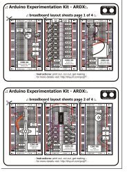
CIRC-09<br />
.:Light:.<br />
.:Photo Resistors:.<br />
What We’re Doing:<br />
Whilst getting input from a potentiometer can be useful<br />
for human controlled experiments, what do we use<br />
when we want an environmentally controlled experiment<br />
We use exactly the same principles but instead of a<br />
potentiometer (twist based resistance) we use a photo resistor (light based<br />
resistance). The Arduino cannot directly sense resistance (it senses voltage) so we<br />
set up a voltage divider ( http://tinyurl.com/2sunta ). The exact voltage at the<br />
sensing pin is calculable, but for our purposes (just sensing relative light) we can<br />
experiment with the values and see what works for us. A low value will occur when<br />
the sensor is well lit while a high value will occur when it is in darkness.<br />
The Circuit:<br />
Parts:<br />
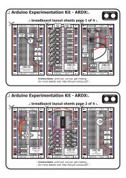
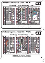
CIRC-09<br />
Breadboard sheet<br />
x1<br />
10k Ohm Resistor<br />
Brown-Black-Orange<br />
x1<br />
2 Pin Header<br />
x4<br />
560 Ohm Resistor<br />
Green-Blue-Brown<br />
x1<br />
Photo-Resistor<br />
x1<br />
Green LED<br />
x1<br />
Wire<br />
Schematic:<br />
Arduino<br />
pin 13<br />
LED<br />
resistor<br />
(560ohm)<br />
+5 volts<br />
photo<br />
resistor<br />
Arduino<br />
analog<br />
pin 0<br />
resistor<br />
(10k ohm)<br />
gnd<br />
(ground) (-)<br />
The Internet<br />
.:download:.<br />
breadboard layout sheet<br />
http://tinyurl.com/cmzfdu<br />
.:view:.<br />
assembling video<br />
http://tinyurl.com/cdldd6<br />
24