ATMega chip full datasheet - UCSD Department of Physics
ATMega chip full datasheet - UCSD Department of Physics
ATMega chip full datasheet - UCSD Department of Physics
- No tags were found...

You also want an ePaper? Increase the reach of your titles
YUMPU automatically turns print PDFs into web optimized ePapers that Google loves.
Features• High Performance, Low Power Atmel ® AVR ® 8-Bit Microcontroller• Advanced RISC Architecture– 131 Powerful Instructions – Most Single Clock Cycle Execution– 32 x 8 General Purpose Working Registers– Fully Static Operation– Up to 20 MIPS Throughput at 20MHz– On-<strong>chip</strong> 2-cycle Multiplier• High Endurance Non-volatile Memory Segments– 4/8/16/32KBytes <strong>of</strong> In-System Self-Programmable Flash program memory– 256/512/512/1KBytes EEPROM– 512/1K/1K/2KBytes Internal SRAM– Write/Erase Cycles: 10,000 Flash/100,000 EEPROM– Data retention: 20 years at 85°C/100 years at 25°C (1)– Optional Boot Code Section with Independent Lock BitsIn-System Programming by On-<strong>chip</strong> Boot ProgramTrue Read-While-Write Operation– Programming Lock for S<strong>of</strong>tware Security• Atmel ® QTouch ® library support– Capacitive touch buttons, sliders and wheels– QTouch and QMatrix ® acquisition– Up to 64 sense channels• Peripheral Features– Two 8-bit Timer/Counters with Separate Prescaler and Compare Mode– One 16-bit Timer/Counter with Separate Prescaler, Compare Mode, and CaptureMode– Real Time Counter with Separate Oscillator– Six PWM Channels– 8-channel 10-bit ADC in TQFP and QFN/MLF packageTemperature Measurement– 6-channel 10-bit ADC in PDIP PackageTemperature Measurement– Programmable Serial USART– Master/Slave SPI Serial Interface– Byte-oriented 2-wire Serial Interface (Philips I 2 C compatible)– Programmable Watchdog Timer with Separate On-<strong>chip</strong> Oscillator– On-<strong>chip</strong> Analog Comparator– Interrupt and Wake-up on Pin Change• Special Microcontroller Features– Power-on Reset and Programmable Brown-out Detection– Internal Calibrated Oscillator– External and Internal Interrupt Sources– Six Sleep Modes: Idle, ADC Noise Reduction, Power-save, Power-down, Standby,and Extended Standby• I/O and Packages– 23 Programmable I/O Lines– 28-pin PDIP, 32-lead TQFP, 28-pad QFN/MLF and 32-pad QFN/MLF• Operating Voltage:– 1.8 - 5.5V• Temperature Range:–-40°C to 85°C• Speed Grade:– 0 - 4MHz@1.8 - 5.5V, 0 - 10MHz@2.7 - 5.5.V, 0 - 20MHz @ 4.5 - 5.5V• Power Consumption at 1MHz, 1.8V, 25°C– Active Mode: 0.2mA– Power-down Mode: 0.1µA– Power-save Mode: 0.75µA (Including 32kHz RTC)8-bit AtmelMicrocontrollerwith 4/8/16/32KBytes In-SystemProgrammableFlashATmega48AATmega48PAATmega88AATmega88PAATmega168AATmega168PAATmega328ATmega328PRev. 8271D–AVR–05/11
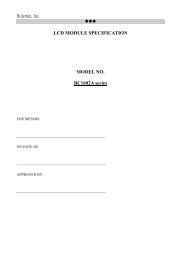
ATmega48A/PA/88A/PA/168A/PA/328/P1. Pin ConfigurationsFigure 1-1.Pinout ATmega48A/PA/88A/PA/168A/PA/328/P32 TQFP Top View28 PDIP(PCINT19/OC2B/INT1) PD3(PCINT20/XCK/T0) PD4GNDVCCGNDVCC(PCINT6/XTAL1/TOSC1) PB6(PCINT7/XTAL2/TOSC2) PB712345678PD2 (INT0/PCINT18)PD1 (TXD/PCINT17)PD0 (RXD/PCINT16)PC6 (RESET/PCINT14)PC5 (ADC5/SCL/PCINT13)PC4 (ADC4/SDA/PCINT12)PC3 (ADC3/PCINT11)PC2 (ADC2/PCINT10)3231302928272625910111213141516(PCINT21/OC0B/T1) PD5(PCINT22/OC0A/AIN0) PD6(PCINT23/AIN1) PD7(PCINT0/CLKO/ICP1) PB0(PCINT1/OC1A) PB1(PCINT2/SS/OC1B) PB2(PCINT3/OC2A/MOSI) PB3(PCINT4/MISO) PB42423222120191817PC1 (ADC1/PCINT9)PC0 (ADC0/PCINT8)ADC7GNDAREFADC6AVCCPB5 (SCK/PCINT5)(PCINT14/RESET) PC6(PCINT16/RXD) PD0(PCINT17/TXD) PD1(PCINT18/INT0) PD2(PCINT19/OC2B/INT1) PD3(PCINT20/XCK/T0) PD4VCCGND(PCINT6/XTAL1/TOSC1) PB6(PCINT7/XTAL2/TOSC2) PB7(PCINT21/OC0B/T1) PD5(PCINT22/OC0A/AIN0) PD6(PCINT23/AIN1) PD7(PCINT0/CLKO/ICP1) PB012345678910111213142827262524232221201918171615PC5 (ADC5/SCL/PCINT13)PC4 (ADC4/SDA/PCINT12)PC3 (ADC3/PCINT11)PC2 (ADC2/PCINT10)PC1 (ADC1/PCINT9)PC0 (ADC0/PCINT8)GNDAREFAVCCPB5 (SCK/PCINT5)PB4 (MISO/PCINT4)PB3 (MOSI/OC2A/PCINT3)PB2 (SS/OC1B/PCINT2)PB1 (OC1A/PCINT1)28 MLF Top View32 MLF Top View3231302928272625(PCINT19/OC2B/INT1) PD3(PCINT20/XCK/T0) PD4GNDVCCGNDVCC(PCINT6/XTAL1/TOSC1) PB6(PCINT7/XTAL2/TOSC2) PB7123456782423222120191817PC1 (ADC1/PCINT9)PC0 (ADC0/PCINT8)ADC7GNDAREFADC6AVCCPB5 (SCK/PCINT5)91011121314151628272625242322PD2 (INT0/PCINT18)PD1 (TXD/PCINT17)PD0 (RXD/PCINT16)PC6 (RESET/PCINT14)PC5 (ADC5/SCL/PCINT13)PC4 (ADC4/SDA/PCINT12)PC3 (ADC3/PCINT11)PC2 (ADC2/PCINT10)(PCINT19/OC2B/INT1) PD3(PCINT20/XCK/T0) PD4VCCGND(PCINT6/XTAL1/TOSC1) PB6(PCINT7/XTAL2/TOSC2) PB7(PCINT21/OC0B/T1) PD5123456789PD2 (INT0/PCINT18)PD1 (TXD/PCINT17)PD0 (RXD/PCINT16)PC6 (RESET/PCINT14)PC5 (ADC5/SCL/PCINT13)PC4 (ADC4/SDA/PCINT12)PC3 (ADC3/PCINT11)101112131421201918171615PC2 (ADC2/PCINT10)PC1 (ADC1/PCINT9)PC0 (ADC0/PCINT8)GNDAREFAVCCPB5 (SCK/PCINT5)NOTE: Bottom pad should be soldered to ground.(PCINT22/OC0A/AIN0) PD6(PCINT23/AIN1) PD7(PCINT0/CLKO/ICP1) PB0(PCINT1/OC1A) PB1(PCINT2/SS/OC1B) PB2(PCINT3/OC2A/MOSI) PB3(PCINT4/MISO) PB4NOTE: Bottom pad should be soldered to ground.(PCINT21/OC0B/T1) PD5(PCINT22/OC0A/AIN0) PD6(PCINT23/AIN1) PD7(PCINT0/CLKO/ICP1) PB0(PCINT1/OC1A) PB1(PCINT2/SS/OC1B) PB2(PCINT3/OC2A/MOSI) PB3(PCINT4/MISO) PB4Table 1-1.32UFBGA - Pinout ATmega48A/48PA/88A/88PA/168A/168PA1 2 3 4 5 6A PD2 PD1 PC6 PC4 PC2 PC1B PD3 PD4 PD0 PC5 PC3 PC0C GND GND ADC7 GNDD VDD VDD AREF ADC6E PB6 PD6 PB0 PB2 AVDD PB5F PB7 PD5 PD7 PB1 PB3 PB48271D–AVR–05/112
ATmega48A/PA/88A/PA/168A/PA/328/P1.1 Pin Descriptions1.1.1 VCC1.1.2 GNDDigital supply voltage.Ground.1.1.3 Port B (PB7:0) XTAL1/XTAL2/TOSC1/TOSC2Port B is an 8-bit bi-directional I/O port with internal pull-up resistors (selected for each bit). ThePort B output buffers have symmetrical drive characteristics with both high sink and sourcecapability. As inputs, Port B pins that are externally pulled low will source current if the pull-upresistors are activated. The Port B pins are tri-stated when a reset condition becomes active,even if the clock is not running.1.1.4 Port C (PC5:0)Depending on the clock selection fuse settings, PB6 can be used as input to the inverting Oscillatoramplifier and input to the internal clock operating circuit.Depending on the clock selection fuse settings, PB7 can be used as output from the invertingOscillator amplifier.If the Internal Calibrated RC Oscillator is used as <strong>chip</strong> clock source, PB7...6 is used asTOSC2...1 input for the Asynchronous Timer/Counter2 if the AS2 bit in ASSR is set.The various special features <strong>of</strong> Port B are elaborated in ”Alternate Functions <strong>of</strong> Port B” on page84 and ”System Clock and Clock Options” on page 27.Port C is a 7-bit bi-directional I/O port with internal pull-up resistors (selected for each bit). ThePC5...0 output buffers have symmetrical drive characteristics with both high sink and sourcecapability. As inputs, Port C pins that are externally pulled low will source current if the pull-upresistors are activated. The Port C pins are tri-stated when a reset condition becomes active,even if the clock is not running.1.1.5 PC6/RESETIf the RSTDISBL Fuse is programmed, PC6 is used as an I/O pin. Note that the electrical characteristics<strong>of</strong> PC6 differ from those <strong>of</strong> the other pins <strong>of</strong> Port C.If the RSTDISBL Fuse is unprogrammed, PC6 is used as a Reset input. A low level on this pinfor longer than the minimum pulse length will generate a Reset, even if the clock is not running.The minimum pulse length is given in Table 29-12 on page 324. Shorter pulses are not guaranteedto generate a Reset.The various special features <strong>of</strong> Port C are elaborated in ”Alternate Functions <strong>of</strong> Port C” on page87.1.1.6 Port D (PD7:0)Port D is an 8-bit bi-directional I/O port with internal pull-up resistors (selected for each bit). ThePort D output buffers have symmetrical drive characteristics with both high sink and sourcecapability. As inputs, Port D pins that are externally pulled low will source current if the pull-upresistors are activated. The Port D pins are tri-stated when a reset condition becomes active,even if the clock is not running.8271D–AVR–05/113
ATmega48A/PA/88A/PA/168A/PA/328/Parchitecture is more code efficient while achieving throughputs up to ten times faster than conventionalCISC microcontrollers.The ATmega48A/PA/88A/PA/168A/PA/328/P provides the following features: 4K/8Kbytes <strong>of</strong> In-System Programmable Flash with Read-While-Write capabilities, 256/512/512/1KbytesEEPROM, 512/1K/1K/2Kbytes SRAM, 23 general purpose I/O lines, 32 general purpose workingregisters, three flexible Timer/Counters with compare modes, internal and externalinterrupts, a serial programmable USART, a byte-oriented 2-wire Serial Interface, an SPI serialport, a 6-channel 10-bit ADC (8 channels in TQFP and QFN/MLF packages), a programmableWatchdog Timer with internal Oscillator, and five s<strong>of</strong>tware selectable power saving modes. TheIdle mode stops the CPU while allowing the SRAM, Timer/Counters, USART, 2-wire Serial Interface,SPI port, and interrupt system to continue functioning. The Power-down mode saves theregister contents but freezes the Oscillator, disabling all other <strong>chip</strong> functions until the next interruptor hardware reset. In Power-save mode, the asynchronous timer continues to run, allowingthe user to maintain a timer base while the rest <strong>of</strong> the device is sleeping. The ADC Noise Reductionmode stops the CPU and all I/O modules except asynchronous timer and ADC, to minimizeswitching noise during ADC conversions. In Standby mode, the crystal/resonator Oscillator isrunning while the rest <strong>of</strong> the device is sleeping. This allows very fast start-up combined with lowpower consumption.Atmel ® <strong>of</strong>fers the QTouch ® library for embedding capacitive touch buttons, sliders and wheelsfunctionality into AVR ® microcontrollers. The patented charge-transfer signal acquisition <strong>of</strong>fersrobust sensing and includes <strong>full</strong>y debounced reporting <strong>of</strong> touch keys and includes Adjacent KeySuppression ® (AKS) technology for unambiguous detection <strong>of</strong> key events. The easy-to-useQTouch Suite toolchain allows you to explore, develop and debug your own touch applications.The device is manufactured using Atmel’s high density non-volatile memory technology. TheOn-<strong>chip</strong> ISP Flash allows the program memory to be reprogrammed In-System through an SPIserial interface, by a conventional non-volatile memory programmer, or by an On-<strong>chip</strong> Boot programrunning on the AVR core. The Boot program can use any interface to download theapplication program in the Application Flash memory. S<strong>of</strong>tware in the Boot Flash section willcontinue to run while the Application Flash section is updated, providing true Read-While-Writeoperation. By combining an 8-bit RISC CPU with In-System Self-Programmable Flash on amonolithic <strong>chip</strong>, the Atmel ATmega48A/PA/88A/PA/168A/PA/328/P is a powerful microcontrollerthat provides a highly flexible and cost effective solution to many embedded control applications.The ATmega48A/PA/88A/PA/168A/PA/328/P AVR is supported with a <strong>full</strong> suite <strong>of</strong> program andsystem development tools including: C Compilers, Macro Assemblers, Program Debugger/Simulators,In-Circuit Emulators, and Evaluation kits.2.2 Comparison Between ProcessorsThe ATmega48A/PA/88A/PA/168A/PA/328/P differ only in memory sizes, boot loader support,and interrupt vector sizes. Table 2-1 summarizes the different memory and interrupt vector sizesfor the devices.Table 2-1.Memory Size SummaryDevice Flash EEPROM RAM Interrupt Vector SizeATmega48A 4KBytes 256Bytes 512Bytes 1 instruction word/vectorATmega48PA 4KBytes 256Bytes 512Bytes 1 instruction word/vectorATmega88A 8KBytes 512Bytes 1KBytes 1 instruction word/vector8271D–AVR–05/116
ATmega48A/PA/88A/PA/168A/PA/328/PTable 2-1.Memory Size Summary (Continued)Device Flash EEPROM RAM Interrupt Vector SizeATmega88PA 8KBytes 512Bytes 1KBytes 1 instruction word/vectorATmega168A 16KBytes 512Bytes 1KBytes 2 instruction words/vectorATmega168PA 16KBytes 512Bytes 1KBytes 2 instruction words/vectorATmega328 32KBytes 1KBytes 2KBytes 2 instruction words/vectorATmega328P 32KBytes 1KBytes 2KBytes 2 instruction words/vectorATmega48A/PA/88A/PA/168A/PA/328/P support a real Read-While-Write Self-Programmingmechanism. There is a separate Boot Loader Section, and the SPM instruction can only executefrom there. In ATmega 48A/48PA there is no Read-While-Write support and no separate BootLoader Section. The SPM instruction can execute from the entire Flash.8271D–AVR–05/117
ATmega48A/PA/88A/PA/168A/PA/328/P3. ResourcesA comprehensive set <strong>of</strong> development tools, application notes and <strong>datasheet</strong>s are available fordownload on http://www.atmel.com/avr.Note: 1.4. Data Retention5. About Code Examples6. Capacitive Touch SensingReliability Qualification results show that the projected data retention failure rate is much lessthan 1 PPM over 20 years at 85°C or 100 years at 25°C.This documentation contains simple code examples that briefly show how to use various parts <strong>of</strong>the device. These code examples assume that the part specific header file is included beforecompilation. Be aware that not all C compiler vendors include bit definitions in the header filesand interrupt handling in C is compiler dependent. Please confirm with the C compiler documentationfor more details.For I/O Registers located in extended I/O map, “IN”, “OUT”, “SBIS”, “SBIC”, “CBI”, and “SBI”instructions must be replaced with instructions that allow access to extended I/O. Typically“LDS” and “STS” combined with “SBRS”, “SBRC”, “SBR”, and “CBR”.The Atmel ® QTouch ® Library provides a simple to use solution to realize touch sensitive interfaceson most Atmel AVR ® microcontrollers. The QTouch Library includes support for the AtmelQTouch and Atmel QMatrix ® acquisition methods.Touch sensing can be added to any application by linking the appropriate Atmel QTouch Libraryfor the AVR Microcontroller. This is done by using a simple set <strong>of</strong> APIs to define the touch channelsand sensors, and then calling the touch sensing API’s to retrieve the channel informationand determine the touch sensor states.The QTouch Library is FREE and downloadable from the Atmel website at the following location:www.atmel.com/qtouchlibrary. For implementation details and other information, refer to theAtmel QTouch Library User Guide - also available for download from Atmel website.8271D–AVR–05/118
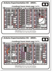
ATmega48A/PA/88A/PA/168A/PA/328/P7. AVR CPU Core7.1 OverviewThis section discusses the AVR core architecture in general. The main function <strong>of</strong> the CPU coreis to ensure correct program execution. The CPU must therefore be able to access memories,perform calculations, control peripherals, and handle interrupts.Figure 7-1.Block Diagram <strong>of</strong> the AVR ArchitectureData Bus 8-bitFlashProgramMemoryProgramCounterStatusand ControlInstructionRegister32 x 8GeneralPurposeRegistrersInterruptUnitSPIUnitInstructionDecoderControl LinesDirect AddressingIndirect AddressingALUWatchdogTimerAnalogComparatorI/O Module1DataSRAMI/O Module 2I/O Module nEEPROMI/O LinesIn order to maximize performance and parallelism, the AVR uses a Harvard architecture – withseparate memories and buses for program and data. Instructions in the program memory areexecuted with a single level pipelining. While one instruction is being executed, the next instructionis pre-fetched from the program memory. This concept enables instructions to be executedin every clock cycle. The program memory is In-System Reprogrammable Flash memory.The fast-access Register File contains 32 x 8-bit general purpose working registers with a singleclock cycle access time. This allows single-cycle Arithmetic Logic Unit (ALU) operation. In a typ-8271D–AVR–05/119
ATmega48A/PA/88A/PA/168A/PA/328/Pical ALU operation, two operands are output from the Register File, the operation is executed,and the result is stored back in the Register File – in one clock cycle.Six <strong>of</strong> the 32 registers can be used as three 16-bit indirect address register pointers for DataSpace addressing – enabling efficient address calculations. One <strong>of</strong> the these address pointerscan also be used as an address pointer for look up tables in Flash program memory. Theseadded function registers are the 16-bit X-, Y-, and Z-register, described later in this section.The ALU supports arithmetic and logic operations between registers or between a constant anda register. Single register operations can also be executed in the ALU. After an arithmetic operation,the Status Register is updated to reflect information about the result <strong>of</strong> the operation.Program flow is provided by conditional and unconditional jump and call instructions, able todirectly address the whole address space. Most AVR instructions have a single 16-bit word format.Every program memory address contains a 16- or 32-bit instruction.Program Flash memory space is divided in two sections, the Boot Program section and theApplication Program section. Both sections have dedicated Lock bits for write and read/writeprotection. The SPM instruction that writes into the Application Flash memory section mustreside in the Boot Program section.During interrupts and subroutine calls, the return address Program Counter (PC) is stored on theStack. The Stack is effectively allocated in the general data SRAM, and consequently the Stacksize is only limited by the total SRAM size and the usage <strong>of</strong> the SRAM. All user programs mustinitialize the SP in the Reset routine (before subroutines or interrupts are executed). The StackPointer (SP) is read/write accessible in the I/O space. The data SRAM can easily be accessedthrough the five different addressing modes supported in the AVR architecture.The memory spaces in the AVR architecture are all linear and regular memory maps.A flexible interrupt module has its control registers in the I/O space with an additional GlobalInterrupt Enable bit in the Status Register. All interrupts have a separate Interrupt Vector in theInterrupt Vector table. The interrupts have priority in accordance with their Interrupt Vector position.The lower the Interrupt Vector address, the higher the priority.The I/O memory space contains 64 addresses for CPU peripheral functions as Control Registers,SPI, and other I/O functions. The I/O Memory can be accessed directly, or as the DataSpace locations following those <strong>of</strong> the Register File, 0x20 - 0x5F. In addition, theATmega48A/PA/88A/PA/168A/PA/328/P has Extended I/O space from 0x60 - 0xFF in SRAMwhere only the ST/STS/STD and LD/LDS/LDD instructions can be used.7.2 ALU – Arithmetic Logic UnitThe high-performance AVR ALU operates in direct connection with all the 32 general purposeworking registers. Within a single clock cycle, arithmetic operations between general purposeregisters or between a register and an immediate are executed. The ALU operations are dividedinto three main categories – arithmetic, logical, and bit-functions. Some implementations <strong>of</strong> thearchitecture also provide a powerful multiplier supporting both signed/unsigned multiplicationand fractional format. See the “Instruction Set” section for a detailed description.7.3 Status RegisterThe Status Register contains information about the result <strong>of</strong> the most recently executed arithmeticinstruction. This information can be used for altering program flow in order to performconditional operations. Note that the Status Register is updated after all ALU operations, as8271D–AVR–05/1110
ATmega48A/PA/88A/PA/168A/PA/328/Pspecified in the Instruction Set Reference. This will in many cases remove the need for using thededicated compare instructions, resulting in faster and more compact code.The Status Register is not automatically stored when entering an interrupt routine and restoredwhen returning from an interrupt. This must be handled by s<strong>of</strong>tware.7.3.1 SREG – AVR Status RegisterThe AVR Status Register – SREG – is defined as:Bit 7 6 5 4 3 2 1 00x3F (0x5F) I T H S V N Z C SREGRead/Write R/W R/W R/W R/W R/W R/W R/W R/WInitial Value 0 0 0 0 0 0 0 0• Bit 7 – I: Global Interrupt EnableThe Global Interrupt Enable bit must be set for the interrupts to be enabled. The individual interruptenable control is then performed in separate control registers. If the Global Interrupt EnableRegister is cleared, none <strong>of</strong> the interrupts are enabled independent <strong>of</strong> the individual interruptenable settings. The I-bit is cleared by hardware after an interrupt has occurred, and is set bythe RETI instruction to enable subsequent interrupts. The I-bit can also be set and cleared bythe application with the SEI and CLI instructions, as described in the instruction set reference.• Bit 6 – T: Bit Copy StorageThe Bit Copy instructions BLD (Bit LoaD) and BST (Bit STore) use the T-bit as source or destinationfor the operated bit. A bit from a register in the Register File can be copied into T by theBST instruction, and a bit in T can be copied into a bit in a register in the Register File by theBLD instruction.• Bit 5 – H: Half Carry FlagThe Half Carry Flag H indicates a Half Carry in some arithmetic operations. Half Carry Is usefulin BCD arithmetic. See the “Instruction Set Description” for detailed information.• Bit 4 – S: Sign Bit, S = N ⊕ VThe S-bit is always an exclusive or between the Negative Flag N and the Two’s ComplementOverflow Flag V. See the “Instruction Set Description” for detailed information.• Bit 3 – V: Two’s Complement Overflow FlagThe Two’s Complement Overflow Flag V supports two’s complement arithmetic. See the“Instruction Set Description” for detailed information.• Bit 2 – N: Negative FlagThe Negative Flag N indicates a negative result in an arithmetic or logic operation. See the“Instruction Set Description” for detailed information.• Bit 1 – Z: Zero FlagThe Zero Flag Z indicates a zero result in an arithmetic or logic operation. See the “InstructionSet Description” for detailed information.• Bit 0 – C: Carry FlagThe Carry Flag C indicates a carry in an arithmetic or logic operation. See the “Instruction SetDescription” for detailed information.8271D–AVR–05/1111
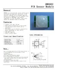
ATmega48A/PA/88A/PA/168A/PA/328/P7.4 General Purpose Register FileThe Register File is optimized for the AVR Enhanced RISC instruction set. In order to achievethe required performance and flexibility, the following input/output schemes are supported by theRegister File:• One 8-bit output operand and one 8-bit result input• Two 8-bit output operands and one 8-bit result input• Two 8-bit output operands and one 16-bit result input• One 16-bit output operand and one 16-bit result inputFigure 7-2 shows the structure <strong>of</strong> the 32 general purpose working registers in the CPU.Figure 7-2.AVR CPU General Purpose Working Registers7 0 Addr.R00x00R10x01R20x02…R130x0DGeneral R14 0x0EPurpose R15 0x0FWorking R16 0x10Registers R17 0x11…R26 0x1A X-register Low ByteR27 0x1B X-register High ByteR28 0x1C Y-register Low ByteR29 0x1D Y-register High ByteR30 0x1E Z-register Low ByteR31 0x1F Z-register High ByteMost <strong>of</strong> the instructions operating on the Register File have direct access to all registers, andmost <strong>of</strong> them are single cycle instructions.As shown in Figure 7-2, each register is also assigned a data memory address, mapping themdirectly into the first 32 locations <strong>of</strong> the user Data Space. Although not being physically implementedas SRAM locations, this memory organization provides great flexibility in access <strong>of</strong> theregisters, as the X-, Y- and Z-pointer registers can be set to index any register in the file.8271D–AVR–05/1112
ATmega48A/PA/88A/PA/168A/PA/328/P7.4.1 The X-register, Y-register, and Z-registerThe registers R26...R31 have some added functions to their general purpose usage. These registersare 16-bit address pointers for indirect addressing <strong>of</strong> the data space. The three indirectaddress registers X, Y, and Z are defined as described in Figure 7-3.Figure 7-3.The X-, Y-, and Z-registers15 XH XL 0X-register 7 0 7 0R27 (0x1B)R26 (0x1A)7.5 Stack Pointer15 YH YL 0Y-register 7 0 7 0R29 (0x1D)R28 (0x1C)15 ZH ZL 0Z-register 7 0 7 0R31 (0x1F)R30 (0x1E)In the different addressing modes these address registers have functions as fixed displacement,automatic increment, and automatic decrement (see the instruction set reference for details).The Stack is mainly used for storing temporary data, for storing local variables and for storingreturn addresses after interrupts and subroutine calls. Note that the Stack is implemented asgrowing from higher to lower memory locations. The Stack Pointer Register always points to thetop <strong>of</strong> the Stack. The Stack Pointer points to the data SRAM Stack area where the Subroutineand Interrupt Stacks are located. A Stack PUSH command will decrease the Stack Pointer.The Stack in the data SRAM must be defined by the program before any subroutine calls areexecuted or interrupts are enabled. Initial Stack Pointer value equals the last address <strong>of</strong> theinternal SRAM and the Stack Pointer must be set to point above start <strong>of</strong> the SRAM, see Table 8-3 on page 19.See Table 7-1 for Stack Pointer details.Table 7-1.Stack Pointer instructionsInstruction Stack pointer DescriptionPUSH Decremented by 1 Data is pushed onto the stackCALLICALLRCALLDecremented by 2POP Incremented by 1 Data is popped from the stackRETRETIIncremented by 2Return address is pushed onto the stack with a subroutine call orinterruptReturn address is popped from the stack with return fromsubroutine or return from interruptThe AVR Stack Pointer is implemented as two 8-bit registers in the I/O space. The number <strong>of</strong>bits actually used is implementation dependent. Note that the data space in some implementations<strong>of</strong> the AVR architecture is so small that only SPL is needed. In this case, the SPH Registerwill not be present.8271D–AVR–05/1113
ATmega48A/PA/88A/PA/168A/PA/328/P7.5.1 SPH and SPL – Stack Pointer High and Stack Pointer Low RegisterBit 15 14 13 12 11 10 9 80x3E (0x5E) SP15 SP14 SP13 SP12 SP11 SP10 SP9 SP8 SPH0x3D (0x5D) SP7 SP6 SP5 SP4 SP3 SP2 SP1 SP0 SPL7 6 5 4 3 2 1 0Read/Write R/W R/W R/W R/W R/W R/W R/W R/WR/W R/W R/W R/W R/W R/W R/W R/WInitial Value RAMEND RAMEND RAMEND RAMEND RAMEND RAMEND RAMEND RAMENDRAMEND RAMEND RAMEND RAMEND RAMEND RAMEND RAMEND RAMEND7.6 Instruction Execution TimingThis section describes the general access timing concepts for instruction execution. The AVRCPU is driven by the CPU clock clk CPU , directly generated from the selected clock source for the<strong>chip</strong>. No internal clock division is used.Figure 7-4 shows the parallel instruction fetches and instruction executions enabled by the Harvardarchitecture and the fast-access Register File concept. This is the basic pipelining conceptto obtain up to 1 MIPS per MHz with the corresponding unique results for functions per cost,functions per clocks, and functions per power-unit.Figure 7-4.The Parallel Instruction Fetches and Instruction ExecutionsT1 T2 T3 T4clkCPU1st Instruction Fetch1st Instruction Execute2nd Instruction Fetch2nd Instruction Execute3rd Instruction Fetch3rd Instruction Execute4th Instruction FetchFigure 7-5 shows the internal timing concept for the Register File. In a single clock cycle an ALUoperation using two register operands is executed, and the result is stored back to the destinationregister.Figure 7-5.Single Cycle ALU OperationT1 T2 T3 T4clk CPUTotal Execution TimeRegister Operands FetchALU Operation ExecuteResult Write Back148271D–AVR–05/11
ATmega48A/PA/88A/PA/168A/PA/328/P7.7 Reset and Interrupt HandlingThe AVR provides several different interrupt sources. These interrupts and the separate ResetVector each have a separate program vector in the program memory space. All interrupts areassigned individual enable bits which must be written logic one together with the Global InterruptEnable bit in the Status Register in order to enable the interrupt. Depending on the ProgramCounter value, interrupts may be automatically disabled when Boot Lock bits BLB02 or BLB12are programmed. This feature improves s<strong>of</strong>tware security. See the section ”Memory Programming”on page 297 for details.The lowest addresses in the program memory space are by default defined as the Reset andInterrupt Vectors. The complete list <strong>of</strong> vectors is shown in ”Interrupts” on page 59. The list alsodetermines the priority levels <strong>of</strong> the different interrupts. The lower the address the higher is thepriority level. RESET has the highest priority, and next is INT0 – the External Interrupt Request0. The Interrupt Vectors can be moved to the start <strong>of</strong> the Boot Flash section by setting the IVSELbit in the MCU Control Register (MCUCR). Refer to ”Interrupts” on page 59 for more information.The Reset Vector can also be moved to the start <strong>of</strong> the Boot Flash section by programming theBOOTRST Fuse, see ”Boot Loader Support – Read-While-Write Self-Programming” on page280.When an interrupt occurs, the Global Interrupt Enable I-bit is cleared and all interrupts are disabled.The user s<strong>of</strong>tware can write logic one to the I-bit to enable nested interrupts. All enabledinterrupts can then interrupt the current interrupt routine. The I-bit is automatically set when aReturn from Interrupt instruction – RETI – is executed.There are basically two types <strong>of</strong> interrupts. The first type is triggered by an event that sets theInterrupt Flag. For these interrupts, the Program Counter is vectored to the actual Interrupt Vectorin order to execute the interrupt handling routine, and hardware clears the correspondingInterrupt Flag. Interrupt Flags can also be cleared by writing a logic one to the flag bit position(s)to be cleared. If an interrupt condition occurs while the corresponding interrupt enable bit iscleared, the Interrupt Flag will be set and remembered until the interrupt is enabled, or the flag iscleared by s<strong>of</strong>tware. Similarly, if one or more interrupt conditions occur while the Global InterruptEnable bit is cleared, the corresponding Interrupt Flag(s) will be set and remembered until theGlobal Interrupt Enable bit is set, and will then be executed by order <strong>of</strong> priority.The second type <strong>of</strong> interrupts will trigger as long as the interrupt condition is present. Theseinterrupts do not necessarily have Interrupt Flags. If the interrupt condition disappears before theinterrupt is enabled, the interrupt will not be triggered.When the AVR exits from an interrupt, it will always return to the main program and execute onemore instruction before any pending interrupt is served.Note that the Status Register is not automatically stored when entering an interrupt routine, norrestored when returning from an interrupt routine. This must be handled by s<strong>of</strong>tware.When using the CLI instruction to disable interrupts, the interrupts will be immediately disabled.No interrupt will be executed after the CLI instruction, even if it occurs simultaneously with theCLI instruction. The following example shows how this can be used to avoid interrupts during thetimed EEPROM write sequence.8271D–AVR–05/1115
ATmega48A/PA/88A/PA/168A/PA/328/PAssembly Code Examplein r16, SREG ; store SREG valuecli ; disable interrupts during timed sequencesbi EECR, EEMPE ; start EEPROM writesbi EECR, EEPEout SREG, r16 ; restore SREG value (I-bit)C Code Examplechar cSREG;cSREG = SREG; /* store SREG value *//* disable interrupts during timed sequence */_CLI();EECR |= (1
ATmega48A/PA/88A/PA/168A/PA/328/P8. AVR Memories8.1 OverviewThis section describes the different memories in the ATmega48A/PA/88A/PA/168A/PA/328/P.The AVR architecture has two main memory spaces, the Data Memory and the Program Memoryspace. In addition, the ATmega48A/PA/88A/PA/168A/PA/328/P features an EEPROMMemory for data storage. All three memory spaces are linear and regular.8.2 In-System Reprogrammable Flash Program MemoryThe ATmega48A/PA/88A/PA/168A/PA/328/P contains 4/8/16/32Kbytes On-<strong>chip</strong> In-SystemReprogrammable Flash memory for program storage. Since all AVR instructions are 16 or 32bits wide, the Flash is organized as 2/4/8/16K x 16. For s<strong>of</strong>tware security, the Flash Programmemory space is divided into two sections, Boot Loader Section and Application Program Sectionin ATmega88PA and ATmega168PA. See SELFPRGEN description in section ”SPMCSR –Store Program Memory Control and Status Register” on page 295 for more details.The Flash memory has an endurance <strong>of</strong> at least 10,000 write/erase cycles. TheATmega48A/PA/88A/PA/168A/PA/328/P Program Counter (PC) is 11/12/13/14 bits wide, thusaddressing the 2/4/8/16K program memory locations. The operation <strong>of</strong> Boot Program sectionand associated Boot Lock bits for s<strong>of</strong>tware protection are described in detail in ”Self-Programmingthe Flash, ATmega 48A/48PA” on page 271 and ”Boot Loader Support – Read-While-WriteSelf-Programming” on page 280. ”Memory Programming” on page 297 contains a detaileddescription on Flash Programming in SPI- or Parallel Programming mode.Constant tables can be allocated within the entire program memory address space (see the LPM– Load Program Memory instruction description).Timing diagrams for instruction fetch and execution are presented in ”Instruction Execution Timing”on page 14.8271D–AVR–05/1117
ATmega48A/PA/88A/PA/168A/PA/328/PFigure 8-1.Program Memory Map ATmega 48A/48PAProgram Memory0x0000Application Flash Section0x7FFFigure 8-2.Program Memory Map ATmega88A, ATmega88PA, ATmega168A,ATmega168PA, ATmega328 and ATmega328PProgram Memory0x0000Application Flash SectionBoot Flash Section0x0FFF/0x1FFF/0x3FFF8271D–AVR–05/1118
ATmega48A/PA/88A/PA/168A/PA/328/P8.3 SRAM Data MemoryFigure 8-3 shows how the ATmega48A/PA/88A/PA/168A/PA/328/P SRAM Memory isorganized.The ATmega48A/PA/88A/PA/168A/PA/328/P is a complex microcontroller with more peripheralunits than can be supported within the 64 locations reserved in the Opcode for the IN and OUTinstructions. For the Extended I/O space from 0x60 - 0xFF in SRAM, only the ST/STS/STD andLD/LDS/LDD instructions can be used.The lower 768/1280/1280/2303 data memory locations address both the Register File, the I/Omemory, Extended I/O memory, and the internal data SRAM. The first 32 locations address theRegister File, the next 64 location the standard I/O memory, then 160 locations <strong>of</strong> Extended I/Omemory, and the next 512/1024/1024/2048 locations address the internal data SRAM.The five different addressing modes for the data memory cover: Direct, Indirect with Displacement,Indirect, Indirect with Pre-decrement, and Indirect with Post-increment. In the RegisterFile, registers R26 to R31 feature the indirect addressing pointer registers.The direct addressing reaches the entire data space.The Indirect with Displacement mode reaches 63 address locations from the base address givenby the Y- or Z-register.When using register indirect addressing modes with automatic pre-decrement and post-increment,the address registers X, Y, and Z are decremented or incremented.The 32 general purpose working registers, 64 I/O Registers, 160 Extended I/O Registers, andthe 512/1024/1024/2048 bytes <strong>of</strong> internal data SRAM in theATmega48A/PA/88A/PA/168A/PA/328/P are all accessible through all these addressing modes.The Register File is described in ”General Purpose Register File” on page 12.Figure 8-3.Data Memory MapData Memory32 Registers64 I/O Registers160 Ext I/O Reg.Internal SRAM(512/1024/1024/2048 x 8)0x0000 - 0x001F0x0020 - 0x005F0x0060 - 0x00FF0x01000x02FF/0x04FF/0x4FF/0x08FF8271D–AVR–05/1119
ATmega48A/PA/88A/PA/168A/PA/328/P8.3.1 Data Memory Access TimesThis section describes the general access timing concepts for internal memory access. Theinternal data SRAM access is performed in two clk CPU cycles as described in Figure 8-4.Figure 8-4.On-<strong>chip</strong> Data SRAM Access CyclesT1 T2 T3clkCPUAddressCompute AddressAddress validDataWRDataRDRead WriteMemory Access InstructionNext Instruction8.4 EEPROM Data MemoryThe ATmega48A/PA/88A/PA/168A/PA/328/P contains 256/512/512/1Kbytes <strong>of</strong> data EEPROMmemory. It is organized as a separate data space, in which single bytes can be read and written.The EEPROM has an endurance <strong>of</strong> at least 100,000 write/erase cycles. The access betweenthe EEPROM and the CPU is described in the following, specifying the EEPROM Address Registers,the EEPROM Data Register, and the EEPROM Control Register.”Memory Programming” on page 297 contains a detailed description on EEPROM Programmingin SPI or Parallel Programming mode.8.4.1 EEPROM Read/Write AccessThe EEPROM Access Registers are accessible in the I/O space.The write access time for the EEPROM is given in Table 8-2. A self-timing function, however,lets the user s<strong>of</strong>tware detect when the next byte can be written. If the user code contains instructionsthat write the EEPROM, some precautions must be taken. In heavily filtered powersupplies, V CC is likely to rise or fall slowly on power-up/down. This causes the device for someperiod <strong>of</strong> time to run at a voltage lower than specified as minimum for the clock frequency used.See ”Preventing EEPROM Corruption” on page 21 for details on how to avoid problems in thesesituations.In order to prevent unintentional EEPROM writes, a specific write procedure must be followed.Refer to the description <strong>of</strong> the EEPROM Control Register for details on this.When the EEPROM is read, the CPU is halted for four clock cycles before the next instruction isexecuted. When the EEPROM is written, the CPU is halted for two clock cycles before the nextinstruction is executed.8271D–AVR–05/1120
ATmega48A/PA/88A/PA/168A/PA/328/P8.4.2 Preventing EEPROM CorruptionDuring periods <strong>of</strong> low V CC, the EEPROM data can be corrupted because the supply voltage istoo low for the CPU and the EEPROM to operate properly. These issues are the same as forboard level systems using EEPROM, and the same design solutions should be applied.An EEPROM data corruption can be caused by two situations when the voltage is too low. First,a regular write sequence to the EEPROM requires a minimum voltage to operate correctly. Secondly,the CPU itself can execute instructions incorrectly, if the supply voltage is too low.EEPROM data corruption can easily be avoided by following this design recommendation:Keep the AVR RESET active (low) during periods <strong>of</strong> insufficient power supply voltage. This canbe done by enabling the internal Brown-out Detector (BOD). If the detection level <strong>of</strong> the internalBOD does not match the needed detection level, an external low V CC reset Protection circuit canbe used. If a reset occurs while a write operation is in progress, the write operation will be completedprovided that the power supply voltage is sufficient.8.5 I/O MemoryThe I/O space definition <strong>of</strong> the ATmega48A/PA/88A/PA/168A/PA/328/P is shown in ”RegisterSummary” on page 533.All ATmega48A/PA/88A/PA/168A/PA/328/P I/Os and peripherals are placed in the I/O space. AllI/O locations may be accessed by the LD/LDS/LDD and ST/STS/STD instructions, transferringdata between the 32 general purpose working registers and the I/O space. I/O Registers withinthe address range 0x00 - 0x1F are directly bit-accessible using the SBI and CBI instructions. Inthese registers, the value <strong>of</strong> single bits can be checked by using the SBIS and SBIC instructions.Refer to the instruction set section for more details. When using the I/O specific commands INand OUT, the I/O addresses 0x00 - 0x3F must be used. When addressing I/O Registers as dataspace using LD and ST instructions, 0x20 must be added to these addresses. TheATmega48A/PA/88A/PA/168A/PA/328/P is a complex microcontroller with more peripheral unitsthan can be supported within the 64 location reserved in Opcode for the IN and OUT instructions.For the Extended I/O space from 0x60 - 0xFF in SRAM, only the ST/STS/STD andLD/LDS/LDD instructions can be used.For compatibility with future devices, reserved bits should be written to zero if accessed.Reserved I/O memory addresses should never be written.Some <strong>of</strong> the Status Flags are cleared by writing a logical one to them. Note that, unlike mostother AVRs, the CBI and SBI instructions will only operate on the specified bit, and can thereforebe used on registers containing such Status Flags. The CBI and SBI instructions work with registers0x00 to 0x1F only.The I/O and peripherals control registers are explained in later sections.8271D–AVR–05/1121
ATmega48A/PA/88A/PA/168A/PA/328/P8.5.1 General Purpose I/O RegistersThe ATmega48A/PA/88A/PA/168A/PA/328/P contains three General Purpose I/O Registers.These registers can be used for storing any information, and they are particularly useful for storingglobal variables and Status Flags. General Purpose I/O Registers within the address range0x00 - 0x1F are directly bit-accessible using the SBI, CBI, SBIS, and SBIC instructions.8.6 Register Description8.6.1 EEARH and EEARL – The EEPROM Address RegisterBit 15 14 13 12 11 10 9 80x22 (0x42) – – – – – – – EEAR8 EEARH0x21 (0x41) EEAR7 EEAR6 EEAR5 EEAR4 EEAR3 EEAR2 EEAR1 EEAR0 EEARL7 6 5 4 3 2 1 0Read/Write R R R R R R R R/WR/W R/W R/W R/W R/W R/W R/W R/WInitial Value 0 0 0 0 0 0 0 XX X X X X X X X8.6.2 EEDR – The EEPROM Data Register• Bits [15:9] – ReservedThese bits are reserved bits in the ATmega48A/PA/88A/PA/168A/PA/328/P and will always readas zero.• Bits 8:0 – EEAR[8:0]: EEPROM AddressThe EEPROM Address Registers – EEARH and EEARL specify the EEPROM address in the256/512/512/1Kbytes EEPROM space. The EEPROM data bytes are addressed linearlybetween 0 and 255/511/511/1023. The initial value <strong>of</strong> EEAR is undefined. A proper value mustbe written before the EEPROM may be accessed.EEAR8 is an unused bit in ATmega 48A/48PA and must always be written to zero.Bit 7 6 5 4 3 2 1 00x20 (0x40) MSB LSB EEDRRead/Write R/W R/W R/W R/W R/W R/W R/W R/WInitial Value 0 0 0 0 0 0 0 0• Bits 7:0 – EEDR[7:0]: EEPROM DataFor the EEPROM write operation, the EEDR Register contains the data to be written to theEEPROM in the address given by the EEAR Register. For the EEPROM read operation, theEEDR contains the data read out from the EEPROM at the address given by EEAR.8.6.3 EECR – The EEPROM Control RegisterBit 7 6 5 4 3 2 1 00x1F (0x3F) – – EEPM1 EEPM0 EERIE EEMPE EEPE EERE EECRRead/Write R R R/W R/W R/W R/W R/W R/WInitial Value 0 0 X X 0 0 X 0• Bits 7:6 – ReservedThese bits are reserved bits in the ATmega48A/PA/88A/PA/168A/PA/328/P and will always readas zero.8271D–AVR–05/1122
ATmega48A/PA/88A/PA/168A/PA/328/P• Bits 5, 4 – EEPM1 and EEPM0: EEPROM Programming Mode BitsThe EEPROM Programming mode bit setting defines which programming action that will be triggeredwhen writing EEPE. It is possible to program data in one atomic operation (erase the oldvalue and program the new value) or to split the Erase and Write operations in two differentoperations. The Programming times for the different modes are shown in Table 8-1. While EEPEis set, any write to EEPMn will be ignored. During reset, the EEPMn bits will be reset to 0b00unless the EEPROM is busy programming.Table 8-1.EEPROM Mode BitsEEPM1EEPM0ProgrammingTimeOperation0 0 3.4ms Erase and Write in one operation (Atomic Operation)0 1 1.8ms Erase Only1 0 1.8ms Write Only1 1 – Reserved for future use• Bit 3 – EERIE: EEPROM Ready Interrupt EnableWriting EERIE to one enables the EEPROM Ready Interrupt if the I bit in SREG is set. WritingEERIE to zero disables the interrupt. The EEPROM Ready interrupt generates a constant interruptwhen EEPE is cleared. The interrupt will not be generated during EEPROM write or SPM.• Bit 2 – EEMPE: EEPROM Master Write EnableThe EEMPE bit determines whether setting EEPE to one causes the EEPROM to be written.When EEMPE is set, setting EEPE within four clock cycles will write data to the EEPROM at theselected address If EEMPE is zero, setting EEPE will have no effect. When EEMPE has beenwritten to one by s<strong>of</strong>tware, hardware clears the bit to zero after four clock cycles. See thedescription <strong>of</strong> the EEPE bit for an EEPROM write procedure.• Bit 1 – EEPE: EEPROM Write EnableThe EEPROM Write Enable Signal EEPE is the write strobe to the EEPROM. When addressand data are correctly set up, the EEPE bit must be written to one to write the value into theEEPROM. The EEMPE bit must be written to one before a logical one is written to EEPE, otherwiseno EEPROM write takes place. The following procedure should be followed when writingthe EEPROM (the order <strong>of</strong> steps 3 and 4 is not essential):1. Wait until EEPE becomes zero.2. Wait until SELFPRGEN in SPMCSR becomes zero.3. Write new EEPROM address to EEAR (optional).4. Write new EEPROM data to EEDR (optional).5. Write a logical one to the EEMPE bit while writing a zero to EEPE in EECR.6. Within four clock cycles after setting EEMPE, write a logical one to EEPE.The EEPROM can not be programmed during a CPU write to the Flash memory. The s<strong>of</strong>twaremust check that the Flash programming is completed before initiating a new EEPROM write.Step 2 is only relevant if the s<strong>of</strong>tware contains a Boot Loader allowing the CPU to program theFlash. If the Flash is never being updated by the CPU, step 2 can be omitted. See ”Boot LoaderSupport – Read-While-Write Self-Programming” on page 280 for details about Bootprogramming.8271D–AVR–05/1123
ATmega48A/PA/88A/PA/168A/PA/328/PCaution: An interrupt between step 5 and step 6 will make the write cycle fail, since theEEPROM Master Write Enable will time-out. If an interrupt routine accessing the EEPROM isinterrupting another EEPROM access, the EEAR or EEDR Register will be modified, causing theinterrupted EEPROM access to fail. It is recommended to have the Global Interrupt Flag clearedduring all the steps to avoid these problems.When the write access time has elapsed, the EEPE bit is cleared by hardware. The user s<strong>of</strong>twarecan poll this bit and wait for a zero before writing the next byte. When EEPE has been set,the CPU is halted for two cycles before the next instruction is executed.• Bit 0 – EERE: EEPROM Read EnableThe EEPROM Read Enable Signal EERE is the read strobe to the EEPROM. When the correctaddress is set up in the EEAR Register, the EERE bit must be written to a logic one to trigger theEEPROM read. The EEPROM read access takes one instruction, and the requested data isavailable immediately. When the EEPROM is read, the CPU is halted for four cycles before thenext instruction is executed.The user should poll the EEPE bit before starting the read operation. If a write operation is inprogress, it is neither possible to read the EEPROM, nor to change the EEAR Register.The calibrated Oscillator is used to time the EEPROM accesses. Table 8-2 lists the typical programmingtime for EEPROM access from the CPU.Table 8-2.EEPROM Programming TimeSymbol Number <strong>of</strong> Calibrated RC Oscillator Cycles Typ Programming TimeEEPROM write(from CPU)26,368 3.3msThe following code examples show one assembly and one C function for writing to theEEPROM. The examples assume that interrupts are controlled (e.g. by disabling interrupts globally)so that no interrupts will occur during execution <strong>of</strong> these functions. The examples alsoassume that no Flash Boot Loader is present in the s<strong>of</strong>tware. If such code is present, theEEPROM write function must also wait for any ongoing SPM command to finish.8271D–AVR–05/1124
ATmega48A/PA/88A/PA/168A/PA/328/PAssembly Code ExampleEEPROM_write:; Wait for completion <strong>of</strong> previous writesbic EECR,EEPErjmp EEPROM_write; Set up address (r18:r17) in address registerout EEARH, r18out EEARL, r17; Write data (r16) to Data Registerout EEDR,r16; Write logical one to EEMPEsbi EECR,EEMPE; Start eeprom write by setting EEPEsbi EECR,EEPEretC Code Examplevoid EEPROM_write(unsigned int uiAddress, unsigned char ucData){/* Wait for completion <strong>of</strong> previous write */while(EECR & (1
ATmega48A/PA/88A/PA/168A/PA/328/PThe next code examples show assembly and C functions for reading the EEPROM. The examplesassume that interrupts are controlled so that no interrupts will occur during execution <strong>of</strong>these functions.Assembly Code ExampleEEPROM_read:; Wait for completion <strong>of</strong> previous writesbic EECR,EEPErjmp EEPROM_read; Set up address (r18:r17) in address registerout EEARH, r18out EEARL, r17; Start eeprom read by writing EEREsbi EECR,EERE; Read data from Data Registerin r16,EEDRretC Code Exampleunsigned char EEPROM_read(unsigned int uiAddress){/* Wait for completion <strong>of</strong> previous write */while(EECR & (1
ATmega48A/PA/88A/PA/168A/PA/328/P9. System Clock and Clock Options9.1 Clock Systems and their DistributionFigure 9-1 presents the principal clock systems in the AVR and their distribution. All <strong>of</strong> the clocksneed not be active at a given time. In order to reduce power consumption, the clocks to modulesnot being used can be halted by using different sleep modes, as described in ”Power Managementand Sleep Modes” on page 40. The clock systems are detailed below.Figure 9-1.Clock DistributionAsynchronousTimer/CounterGeneral I/OModulesADCCPU CoreRAMFlash andEEPROMclk ADCclk I/OAVR ClockControl Unitclk CPUclk ASYclk FLASHSystem ClockPrescalerReset LogicWatchdog TimerSource clockWatchdog clockClockMultiplexerWatchdogOscillatorTimer/CounterOscillatorExternal ClockCrystalOscillatorLow-frequencyCrystal OscillatorCalibrated RCOscillator9.1.1 CPU Clock – clk CPUThe CPU clock is routed to parts <strong>of</strong> the system concerned with operation <strong>of</strong> the AVR core.Examples <strong>of</strong> such modules are the General Purpose Register File, the Status Register and thedata memory holding the Stack Pointer. Halting the CPU clock inhibits the core from performinggeneral operations and calculations.9.1.2 I/O Clock – clk I/OThe I/O clock is used by the majority <strong>of</strong> the I/O modules, like Timer/Counters, SPI, and USART.The I/O clock is also used by the External Interrupt module, but note that start condition detectionin the USI module is carried out asynchronously when clk I/O is halted, TWI addressrecognition in all sleep modes.Note:Note that if a level triggered interrupt is used for wake-up from Power-down, the required levelmust be held long enough for the MCU to complete the wake-up to trigger the level interrupt. If thelevel disappears before the end <strong>of</strong> the Start-up Time, the MCU will still wake up, but no interruptwill be generated. The start-up time is defined by the SUT and CKSEL Fuses as described in”System Clock and Clock Options” on page 27.8271D–AVR–05/1127
ATmega48A/PA/88A/PA/168A/PA/328/P9.1.3 Flash Clock – clk FLASHThe Flash clock controls operation <strong>of</strong> the Flash interface. The Flash clock is usually active simultaneouslywith the CPU clock.9.1.4 Asynchronous Timer Clock – clk ASYThe Asynchronous Timer clock allows the Asynchronous Timer/Counter to be clocked directlyfrom an external clock or an external 32kHz clock crystal. The dedicated clock domain allowsusing this Timer/Counter as a real-time counter even when the device is in sleep mode.9.1.5 ADC Clock – clk ADCThe ADC is provided with a dedicated clock domain. This allows halting the CPU and I/O clocksin order to reduce noise generated by digital circuitry. This gives more accurate ADC conversionresults.9.2 Clock SourcesThe device has the following clock source options, selectable by Flash Fuse bits as shownbelow. The clock from the selected source is input to the AVR clock generator, and routed to theappropriate modules.Table 9-1. Device Clocking Options Select (1)Device Clocking Option CKSEL3...0Low Power Crystal Oscillator 1111 - 1000Full Swing Crystal Oscillator 0111 - 0110Low Frequency Crystal Oscillator 0101 - 0100Internal 128kHz RC Oscillator 0011Calibrated Internal RC Oscillator 0010External Clock 0000Reserved 0001Note: 1. For all fuses “1” means unprogrammed while “0” means programmed.9.2.1 Default Clock SourceThe device is shipped with internal RC oscillator at 8.0MHz and with the fuse CKDIV8 programmed,resulting in 1.0MHz system clock. The startup time is set to maximum and time-outperiod enabled. (CKSEL = "0010", SUT = "10", CKDIV8 = "0"). The default setting ensures thatall users can make their desired clock source setting using any available programming interface.9.2.2 Clock Startup SequenceAny clock source needs a sufficient V CC to start oscillating and a minimum number <strong>of</strong> oscillatingcycles before it can be considered stable.To ensure sufficient V CC , the device issues an internal reset with a time-out delay (t TOUT ) afterthe device reset is released by all other reset sources. ”System Control and Reset” on page 48describes the start conditions for the internal reset. The delay (t TOUT ) is timed from the WatchdogOscillator and the number <strong>of</strong> cycles in the delay is set by the SUTx and CKSELx fuse bits. The8271D–AVR–05/1128
ATmega48A/PA/88A/PA/168A/PA/328/Pselectable delays are shown in Table 9-2. The frequency <strong>of</strong> the Watchdog Oscillator is voltagedependent as shown in ”Typical Characteristics” on page 332.Table 9-2.Number <strong>of</strong> Watchdog Oscillator CyclesTyp Time-out (V CC = 5.0V) Typ Time-out (V CC = 3.0V) Number <strong>of</strong> Cycles0ms 0ms 04.1ms 4.3ms 51265ms 69ms 8K (8,192)Main purpose <strong>of</strong> the delay is to keep the AVR in reset until it is supplied with minimum V CC . Thedelay will not monitor the actual voltage and it will be required to select a delay longer than theV CC rise time. If this is not possible, an internal or external Brown-Out Detection circuit should beused. A BOD circuit will ensure sufficient V CC before it releases the reset, and the time-out delaycan be disabled. Disabling the time-out delay without utilizing a Brown-Out Detection circuit isnot recommended.The oscillator is required to oscillate for a minimum number <strong>of</strong> cycles before the clock is consideredstable. An internal ripple counter monitors the oscillator output clock, and keeps the internalreset active for a given number <strong>of</strong> clock cycles. The reset is then released and the device willstart to execute. The recommended oscillator start-up time is dependent on the clock type, andvaries from 6 cycles for an externally applied clock to 32K cycles for a low frequency crystal.The start-up sequence for the clock includes both the time-out delay and the start-up time whenthe device starts up from reset. When starting up from Power-save or Power-down mode, V CC isassumed to be at a sufficient level and only the start-up time is included.9.3 Low Power Crystal OscillatorPins XTAL1 and XTAL2 are input and output, respectively, <strong>of</strong> an inverting amplifier which can beconfigured for use as an On-<strong>chip</strong> Oscillator, as shown in Figure 9-2 on page 30. Either a quartzcrystal or a ceramic resonator may be used.This Crystal Oscillator is a low power oscillator, with reduced voltage swing on the XTAL2 output.It gives the lowest power consumption, but is not capable <strong>of</strong> driving other clock inputs, andmay be more susceptible to noise in noisy environments. In these cases, refer to the ”Full SwingCrystal Oscillator” on page 31.C1 and C2 should always be equal for both crystals and resonators. The optimal value <strong>of</strong> thecapacitors depends on the crystal or resonator in use, the amount <strong>of</strong> stray capacitance, and theelectromagnetic noise <strong>of</strong> the environment. Some initial guidelines for choosing capacitors foruse with crystals are given in Table 9-3 on page 30. For ceramic resonators, the capacitor valuesgiven by the manufacturer should be used.8271D–AVR–05/1129
ATmega48A/PA/88A/PA/168A/PA/328/PFigure 9-2.Crystal Oscillator ConnectionsC2C1XTAL2 (TOSC2)XTAL1 (TOSC1)GNDThe Low Power Oscillator can operate in three different modes, each optimized for a specific frequencyrange. The operating mode is selected by the fuses CKSEL3...1 as shown in Table 9-3on page 30.Table 9-3. Low Power Crystal Oscillator Operating Modes (3)Frequency Range(MHz)Recommended Range forCapacitors C1 and C2 (pF) CKSEL3...1 (1)0.4 - 0.9 – 100 (2)0.9 - 3.0 12 - 22 1013.0 - 8.0 12 - 22 1108.0 - 16.0 12 - 22 111Notes: 1. This is the recommended CKSEL settings for the difference frequency ranges.2. This option should not be used with crystals, only with ceramic resonators.3. If the crystal frequency exceeds the specification <strong>of</strong> the device (depends on V CC ), the CKDIV8Fuse can be programmed in order to divide the internal frequency by 8. It must be ensuredthat the resulting divided clock meets the frequency specification <strong>of</strong> the device.The CKSEL0 Fuse together with the SUT1...0 Fuses select the start-up times as shown in Table9-4.Table 9-4.Oscillator Source /Power ConditionsCeramic resonator, fastrising powerCeramic resonator, slowlyrising powerCeramic resonator, BODenabledCeramic resonator, fastrising powerCeramic resonator, slowlyrising powerStart-up Times for the Low Power Crystal Oscillator Clock SelectionStart-up Time fromPower-down andPower-saveAdditional Delayfrom Reset(V CC = 5.0V) CKSEL0 SUT1...0258 CK 14CK + 4.1ms (1) 0 00258 CK 14CK + 65ms (1) 0 011K CK 14CK (2) 0 101K CK 14CK + 4.1ms (2) 0 111K CK 14CK + 65ms (2) 1 008271D–AVR–05/1130
ATmega48A/PA/88A/PA/168A/PA/328/PTable 9-4.Oscillator Source /Power ConditionsCrystal Oscillator, BODenabledCrystal Oscillator, fastrising powerCrystal Oscillator, slowlyrising power16K CK 14CK 1 0116K CK 14CK + 4.1ms 1 10Notes: 1. These options should only be used when not operating close to the maximum frequency <strong>of</strong> thedevice, and only if frequency stability at start-up is not important for the application. Theseoptions are not suitable for crystals.2. These options are intended for use with ceramic resonators and will ensure frequency stabilityat start-up. They can also be used with crystals when not operating close to the maximum frequency<strong>of</strong> the device, and if frequency stability at start-up is not important for the application.9.4 Full Swing Crystal OscillatorPins XTAL1 and XTAL2 are input and output, respectively, <strong>of</strong> an inverting amplifier which can beconfigured for use as an On-<strong>chip</strong> Oscillator, as shown in Figure 9-2 on page 30. Either a quartzcrystal or a ceramic resonator may be used.This Crystal Oscillator is a <strong>full</strong> swing oscillator, with rail-to-rail swing on the XTAL2 output. This isuseful for driving other clock inputs and in noisy environments. The current consumption ishigher than the ”Low Power Crystal Oscillator” on page 29. Note that the Full Swing CrystalOscillator will only operate for V CC = 2.7 - 5.5 volts.C1 and C2 should always be equal for both crystals and resonators. The optimal value <strong>of</strong> thecapacitors depends on the crystal or resonator in use, the amount <strong>of</strong> stray capacitance, and theelectromagnetic noise <strong>of</strong> the environment. Some initial guidelines for choosing capacitors foruse with crystals are given in Table 9-6 on page 32. For ceramic resonators, the capacitor valuesgiven by the manufacturer should be used.The operating mode is selected by the fuses CKSEL3...1 as shown in Table 9-5.Table 9-5.Frequency Range (1)(MHz)Start-up Times for the Low Power Crystal Oscillator Clock Selection (Continued)Start-up Time fromPower-down andPower-save16K CK 14CK + 65ms 1 11Full Swing Crystal Oscillator operating modesRecommended Range forCapacitors C1 and C2 (pF)Additional Delayfrom Reset(V CC = 5.0V) CKSEL0 SUT1...0CKSEL3...10.4 - 20 12 - 22 011Notes: 1. If the cryatal frequency exceeds the specification <strong>of</strong> the device (depends on V CC ), the CKDIV8Fuse can be programmed in order to divide the internal frequency by 8. It must be ensuredthat the resulting divided clock meets the frequency specification <strong>of</strong> the device.8271D–AVR–05/1131
ATmega48A/PA/88A/PA/168A/PA/328/PFigure 9-3.Crystal Oscillator ConnectionsC2C1XTAL2 (TOSC2)XTAL1 (TOSC1)GNDTable 9-6.Oscillator Source /Power ConditionsCeramic resonator, fastrising powerCeramic resonator, slowlyrising powerCeramic resonator, BODenabledCeramic resonator, fastrising powerCeramic resonator, slowlyrising powerCrystal Oscillator, BODenabledCrystal Oscillator, fastrising powerCrystal Oscillator, slowlyrising powerStart-up Times for the Full Swing Crystal Oscillator Clock SelectionStart-up Time fromPower-down andPower-saveAdditional Delayfrom Reset(V CC = 5.0V) CKSEL0 SUT1...0258 CK 14CK + 4.1ms (1) 0 00258 CK 14CK + 65ms (1) 0 011K CK 14CK (2) 0 101K CK 14CK + 4.1ms (2) 0 111K CK 14CK + 65ms (2) 1 0016K CK 14CK 1 0116K CK 14CK + 4.1ms 1 1016K CK 14CK + 65ms 1 11Notes: 1. These options should only be used when not operating close to the maximum frequency <strong>of</strong> thedevice, and only if frequency stability at start-up is not important for the application. Theseoptions are not suitable for crystals.2. These options are intended for use with ceramic resonators and will ensure frequency stabilityat start-up. They can also be used with crystals when not operating close to the maximum frequency<strong>of</strong> the device, and if frequency stability at start-up is not important for the application.8271D–AVR–05/1132
ATmega48A/PA/88A/PA/168A/PA/328/P9.5 Low Frequency Crystal OscillatorThe Low-frequency Crystal Oscillator is optimized for use with a 32.768kHz watch crystal. Whenselecting crystals, load capacitance and crystal’s Equivalent Series Resistance, ESR must betaken into consideration. Both values are specified by the crystal vendor.ATmega48A/PA/88A/PA/168A/PA/328/P oscillator is optimized for very low power consumption,and thus when selecting crystals, see Table for maximum ESR recommendations on 6.5pF,9.0pF and 12.5pF crystalsTable 9-7.Maximum ESR Recommendation for 32.768kHz CrystalCrystal CL (pF) Max ESR [kΩ] (1)6.5 759.0 6512.5 30Note: 1. Maximum ESR is typical value based on characterizationThe Low-frequency Crystal Oscillator provides an internal load capacitance, see Table 9-8 ateach TOSC pin.Table 9-8.Capacitance for Low-frequency OscillatorDevice 32kHz Osc. Type Cap(Xtal1/Tosc1) Cap(Xtal2/Tosc2)ATmega48A/PA/88A/PA/168A/PA/328/PSystem Osc. 18pF 8pFTimer Osc. 18pF 8pFThe capacitance (Ce+Ci) needed at each TOSC pin can be calculated by using:C = 2 ⋅ CL –where:C s– Ce - is optional external capacitors as described in Figure 9-2 on page 30– Ci - is the pin capacitance in Table 9-8– CL - is the load capacitance for a 32.768kHz crystal specified by the crystal vendor– CS - is the total stray capacitance for one TOSC pin.Crystals specifying load capacitance (CL) higher than 6 pF, require external capacitors appliedas described in Figure 9-2 on page 30.The Low-frequency Crystal Oscillator must be selected by setting the CKSEL Fuses to “0110” or“0111”, as shown in Table 9-10 on page 34. Start-up times are determined by the SUT Fuses asshown in Table 9-9.Table 9-9.Start-up Times for the Low-frequency Crystal Oscillator Clock SelectionSUT1...0 Additional Delay from Reset (V CC = 5.0V) Recommended Usage00 4 CK Fast rising power or BOD enabled01 4 CK + 4.1ms Slowly rising power10 4 CK + 65ms Stable frequency at start-up11 Reserved8271D–AVR–05/1133
ATmega48A/PA/88A/PA/168A/PA/328/PTable 9-10.CKSEL3...0Start-up Times for the Low-frequency Crystal Oscillator Clock SelectionStart-up Time fromPower-down and Power-save0100 (1) 1K CKRecommended Usage0101 32K CK Stable frequency at start-upNote: 1. This option should only be used if frequency stability at start-up is not important for theapplication9.6 Calibrated Internal RC OscillatorBy default, the Internal RC Oscillator provides an approximate 8.0MHz clock. Though voltageand temperature dependent, this clock can be very accurately calibrated by the user. See Table29-10 on page 323 for more details. The device is shipped with the CKDIV8 Fuse programmed.See ”System Clock Prescaler” on page 36 for more details.This clock may be selected as the system clock by programming the CKSEL Fuses as shown inTable 9-11. If selected, it will operate with no external components. During reset, hardware loadsthe pre-programmed calibration value into the OSCCAL Register and thereby automatically calibratesthe RC Oscillator. The accuracy <strong>of</strong> this calibration is shown as Factory calibration in Table29-10 on page 323.By changing the OSCCAL register from SW, see ”OSCCAL – Oscillator Calibration Register” onpage 38, it is possible to get a higher calibration accuracy than by using the factory calibration.The accuracy <strong>of</strong> this calibration is shown as User calibration in Table 29-10 on page 323.When this Oscillator is used as the <strong>chip</strong> clock, the Watchdog Oscillator will still be used for theWatchdog Timer and for the Reset Time-out. For more information on the pre-programmed calibrationvalue, see the section ”Calibration Byte” on page 302.Table 9-11.Notes: 1. The device is shipped with this option selected.2. If 8MHz frequency exceeds the specification <strong>of</strong> the device (depends on V CC ), the CKDIV8Fuse can be programmed in order to divide the internal frequency by 8.When this Oscillator is selected, start-up times are determined by the SUT Fuses as shown inTable 9-12.Table 9-12.Power ConditionsInternal Calibrated RC Oscillator Operating ModesFrequency Range (2) (MHz) CKSEL3...07.3 - 8.1 0010 (1)Start-up times for the internal calibrated RC Oscillator clock selectionStart-up Time from Powerdownand Power-saveAdditional Delay fromReset (V CC = 5.0V)Note: 1. If the RSTDISBL fuse is programmed, this start-up time will be increased to14CK + 4.1ms to ensure programming mode can be entered.2. The device is shipped with this option selected.SUT1...0BOD enabled 6 CK 14CK (1) 00Fast rising power 6 CK 14CK + 4.1ms 01Slowly rising power 6 CK 14CK + 65ms (2) 10Reserved 118271D–AVR–05/1134
ATmega48A/PA/88A/PA/168A/PA/328/P9.7 128kHz Internal OscillatorThe 128kHz internal Oscillator is a low power Oscillator providing a clock <strong>of</strong> 128kHz. The frequencyis nominal at 3V and 25°C. This clock may be select as the system clock byprogramming the CKSEL Fuses to “11” as shown in Table 9-13.Table 9-13.128kHz Internal Oscillator Operating ModesNominal Frequency (1)CKSEL3...0128kHz 0011Note: 1. Note that the 128kHz oscillator is a very low power clock source, and is not designed for highaccuracy.When this clock source is selected, start-up times are determined by the SUT Fuses as shown inTable 9-14.Table 9-14.Start-up Times for the 128kHz Internal OscillatorPower ConditionsStart-up Time from Powerdownand Power-saveAdditional Delay fromResetSUT1...0BOD enabled 6 CK 14CK (1) 00Fast rising power 6 CK 14CK + 4ms 01Slowly rising power 6 CK 14CK + 64ms 10Reserved 11Note: 1. If the RSTDISBL fuse is programmed, this start-up time will be increased to14CK + 4.1ms to ensure programming mode can be entered.9.8 External ClockTo drive the device from an external clock source, XTAL1 should be driven as shown in Figure9-4. To run the device on an external clock, the CKSEL Fuses must be programmed to “0000”(see Table 9-15).Table 9-15.Crystal Oscillator Clock FrequencyFrequency CKSEL3...00 - 20MHz 0000Figure 9-4.External Clock Drive ConfigurationPB7XTAL2EXTERNALCLOCKSIGNALXTAL1GNDWhen this clock source is selected, start-up times are determined by the SUT Fuses as shown inTable 9-16.8271D–AVR–05/1135
ATmega48A/PA/88A/PA/168A/PA/328/PTable 9-16.Power ConditionsStart-up Times for the External Clock SelectionStart-up Time from Powerdownand Power-saveAdditional Delay fromReset (V CC = 5.0V)SUT1...0BOD enabled 6 CK 14CK 00Fast rising power 6 CK 14CK + 4.1ms 01Slowly rising power 6 CK 14CK + 65ms 10Reserved 11When applying an external clock, it is required to avoid sudden changes in the applied clock frequencyto ensure stable operation <strong>of</strong> the MCU. A variation in frequency <strong>of</strong> more than 2% fromone clock cycle to the next can lead to unpredictable behavior. If changes <strong>of</strong> more than 2% isrequired, ensure that the MCU is kept in Reset during the changes.Note that the System Clock Prescaler can be used to implement run-time changes <strong>of</strong> the internalclock frequency while still ensuring stable operation. Refer to ”System Clock Prescaler” on page36 for details.9.9 Clock Output BufferThe device can output the system clock on the CLKO pin. To enable the output, the CKOUTFuse has to be programmed. This mode is suitable when the <strong>chip</strong> clock is used to drive other circuitson the system. The clock also will be output during reset, and the normal operation <strong>of</strong> I/Opin will be overridden when the fuse is programmed. Any clock source, including the internal RCOscillator, can be selected when the clock is output on CLKO. If the System Clock Prescaler isused, it is the divided system clock that is output.9.10 Timer/Counter OscillatorATmega48A/PA/88A/PA/168A/PA/328/P uses the same crystal oscillator for Low-frequencyOscillator and Timer/Counter Oscillator. See ”Low Frequency Crystal Oscillator” on page 33 fordetails on the oscillator and crystal requirements.ATmega48A/PA/88A/PA/168A/PA/328/P share the Timer/Counter Oscillator Pins (TOSC1 andTOSC2) with XTAL1 and XTAL2. When using the Timer/Counter Oscillator, the system clockneeds to be four times the oscillator frequency. Due to this and the pin sharing, the Timer/CounterOscillator can only be used when the Calibrated Internal RC Oscillator is selected as systemclock source.Applying an external clock source to TOSC1 can be done if EXTCLK in the ASSR Register iswritten to logic one. See ”Asynchronous Operation <strong>of</strong> Timer/Counter2” on page 157 for furtherdescription on selecting external clock as input instead <strong>of</strong> a 32.768kHz watch crystal.9.11 System Clock PrescalerThe ATmega48A/PA/88A/PA/168A/PA/328/P has a system clock prescaler, and the systemclock can be divided by setting the ”CLKPR – Clock Prescale Register” on page 387. This featurecan be used to decrease the system clock frequency and the power consumption when therequirement for processing power is low. This can be used with all clock source options, and itwill affect the clock frequency <strong>of</strong> the CPU and all synchronous peripherals. clk I/O , clk ADC , clk CPU ,and clk FLASH are divided by a factor as shown in Table 29-12 on page 324.8271D–AVR–05/1136
ATmega48A/PA/88A/PA/168A/PA/328/PWhen switching between prescaler settings, the System Clock Prescaler ensures that noglitches occurs in the clock system. It also ensures that no intermediate frequency is higher thanneither the clock frequency corresponding to the previous setting, nor the clock frequency correspondingto the new setting. The ripple counter that implements the prescaler runs at thefrequency <strong>of</strong> the undivided clock, which may be faster than the CPU's clock frequency. Hence, itis not possible to determine the state <strong>of</strong> the prescaler - even if it were readable, and the exacttime it takes to switch from one clock division to the other cannot be exactly predicted. From thetime the CLKPS values are written, it takes between T1 + T2 and T1 + 2 * T2 before the newclock frequency is active. In this interval, 2 active clock edges are produced. Here, T1 is the previousclock period, and T2 is the period corresponding to the new prescaler setting.To avoid unintentional changes <strong>of</strong> clock frequency, a special write procedure must be followedto change the CLKPS bits:1. Write the Clock Prescaler Change Enable (CLKPCE) bit to one and all other bits inCLKPR to zero.2. Within four cycles, write the desired value to CLKPS while writing a zero to CLKPCE.Interrupts must be disabled when changing prescaler setting to make sure the write procedure isnot interrupted.8271D–AVR–05/1137
ATmega48A/PA/88A/PA/168A/PA/328/P9.12 Register Description9.12.1 OSCCAL – Oscillator Calibration RegisterBit 7 6 5 4 3 2 1 0(0x66) CAL7 CAL6 CAL5 CAL4 CAL3 CAL2 CAL1 CAL0 OSCCALRead/Write R/W R/W R/W R/W R/W R/W R/W R/WInitial ValueDevice Specific Calibration Value9.12.2 CLKPR – Clock Prescale Register• Bits 7:0 – CAL[7:0]: Oscillator Calibration ValueThe Oscillator Calibration Register is used to trim the Calibrated Internal RC Oscillator toremove process variations from the oscillator frequency. A pre-programmed calibration value isautomatically written to this register during <strong>chip</strong> reset, giving the Factory calibrated frequency asspecified in Table 29-10 on page 323. The application s<strong>of</strong>tware can write this register to changethe oscillator frequency. The oscillator can be calibrated to frequencies as specified in Table 29-10 on page 323. Calibration outside that range is not guaranteed.Note that this oscillator is used to time EEPROM and Flash write accesses, and these writetimes will be affected accordingly. If the EEPROM or Flash are written, do not calibrate to morethan 8.8MHz. Otherwise, the EEPROM or Flash write may fail.The CAL7 bit determines the range <strong>of</strong> operation for the oscillator. Setting this bit to 0 gives thelowest frequency range, setting this bit to 1 gives the highest frequency range. The two frequencyranges are overlapping, in other words a setting <strong>of</strong> OSCCAL = 0x7F gives a higherfrequency than OSCCAL = 0x80.The CAL6...0 bits are used to tune the frequency within the selected range. A setting <strong>of</strong> 0x00gives the lowest frequency in that range, and a setting <strong>of</strong> 0x7F gives the highest frequency in therange.Bit 7 6 5 4 3 2 1 0(0x61) CLKPCE – – – CLKPS3 CLKPS2 CLKPS1 CLKPS0 CLKPRRead/Write R/W R R R R/W R/W R/W R/WInitial Value 0 0 0 0 See Bit Description• Bit 7 – CLKPCE: Clock Prescaler Change EnableThe CLKPCE bit must be written to logic one to enable change <strong>of</strong> the CLKPS bits. The CLKPCEbit is only updated when the other bits in CLKPR are simultaneously written to zero. CLKPCE iscleared by hardware four cycles after it is written or when CLKPS bits are written. Rewriting theCLKPCE bit within this time-out period does neither extend the time-out period, nor clear theCLKPCE bit.• Bits 3:0 – CLKPS[3:0]: Clock Prescaler Select Bits 3 - 0These bits define the division factor between the selected clock source and the internal systemclock. These bits can be written run-time to vary the clock frequency to suit the applicationrequirements. As the divider divides the master clock input to the MCU, the speed <strong>of</strong> all synchronousperipherals is reduced when a division factor is used. The division factors are given inTable 9-17 on page 39.8271D–AVR–05/1138
ATmega48A/PA/88A/PA/168A/PA/328/PThe CKDIV8 Fuse determines the initial value <strong>of</strong> the CLKPS bits. If CKDIV8 is unprogrammed,the CLKPS bits will be reset to “0000”. If CKDIV8 is programmed, CLKPS bits are reset to“0011”, giving a division factor <strong>of</strong> 8 at start up. This feature should be used if the selected clocksource has a higher frequency than the maximum frequency <strong>of</strong> the device at the present operatingconditions. Note that any value can be written to the CLKPS bits regardless <strong>of</strong> the CKDIV8Fuse setting. The Application s<strong>of</strong>tware must ensure that a sufficient division factor is chosen ifthe selected clock source has a higher frequency than the maximum frequency <strong>of</strong> the device atthe present operating conditions. The device is shipped with the CKDIV8 Fuse programmed.Table 9-17.Clock Prescaler SelectCLKPS3 CLKPS2 CLKPS1 CLKPS0 Clock Division Factor0 0 0 0 10 0 0 1 20 0 1 0 40 0 1 1 80 1 0 0 160 1 0 1 320 1 1 0 640 1 1 1 1281 0 0 0 2561 0 0 1 Reserved1 0 1 0 Reserved1 0 1 1 Reserved1 1 0 0 Reserved1 1 0 1 Reserved1 1 1 0 Reserved1 1 1 1 Reserved8271D–AVR–05/1139
ATmega48A/PA/88A/PA/168A/PA/328/P10. Power Management and Sleep ModesSleep modes enable the application to shut down unused modules in the MCU, thereby savingpower. The AVR provides various sleep modes allowing the user to tailor the power consumptionto the application’s requirements.When enabled, the Brown-out Detector (BOD) actively monitors the power supply voltage duringthe sleep periods. To further save power, it is possible to disable the BOD in some sleep modes.See ”BOD Disable(1)” on page 41 for more details.10.1 Sleep ModesFigure 9-1 on page 27 presents the different clock systems in theATmega48A/PA/88A/PA/168A/PA/328/P, and their distribution. The figure is helpful in selectingan appropriate sleep mode. Table 10-1 shows the different sleep modes, their wake up sourcesBOD disable ability. (1)Note: 1. BOD disable is only available for ATmega48PA/88PA/168PA/328P.Table 10-1.Active Clock Domains and Wake-up Sources in the Different Sleep Modes.Active Clock Domains Oscillators Wake-up Sourcesclk CPUclk FLASHclk IOclk ADCSleep ModeIdle X X X X X (2) X X X X X X XNotes: 1. Only recommended with external crystal or resonator selected as clock source.2. If Timer/Counter2 is running in asynchronous mode.3. For INT1 and INT0, only level interrupt.clk ASYMain ClockSource EnabledTimer OscillatorEnabledADC NoiseX X X X (2) X (3) X X (2) X X XReductionPower-down X (3) X X XPower-save X X (2) X (3) X X X XStandby (1) X X (3) X X XExtendedStandbyINT1, INT0 andPin ChangeTWI AddressMatchTimer2SPM/EEPROMReadyX (2) X X (2) X (3) X X X XADCWDTOther I/OS<strong>of</strong>twareBOD DisableTo enter any <strong>of</strong> the six sleep modes, the SE bit in SMCR must be written to logic one and aSLEEP instruction must be executed. The SM2, SM1, and SM0 bits in the SMCR Register selectwhich sleep mode (Idle, ADC Noise Reduction, Power-down, Power-save, Standby, or ExtendedStandby) will be activated by the SLEEP instruction. See Table 10-2 on page 45 for a summary.If an enabled interrupt occurs while the MCU is in a sleep mode, the MCU wakes up. The MCUis then halted for four cycles in addition to the start-up time, executes the interrupt routine, andresumes execution from the instruction following SLEEP. The contents <strong>of</strong> the Register File andSRAM are unaltered when the device wakes up from sleep. If a reset occurs during sleep mode,the MCU wakes up and executes from the Reset Vector.8271D–AVR–05/1140
ATmega48A/PA/88A/PA/168A/PA/328/P10.2 BOD Disable (1) When the Brown-out Detector (BOD) is enabled by BODLEVEL fuses - see Table 28-7 on page299 and onwards, the BOD is actively monitoring the power supply voltage during a sleepperiod. To save power, it is possible to disable the BOD by s<strong>of</strong>tware for some <strong>of</strong> the sleepmodes, see Table 10-1 on page 40. The sleep mode power consumption will then be at thesame level as when BOD is globally disabled by fuses. If BOD is disabled in s<strong>of</strong>tware, the BODfunction is turned <strong>of</strong>f immediately after entering the sleep mode. Upon wake-up from sleep, BODis automatically enabled again. This ensures safe operation in case the V CC level has droppedduring the sleep period.When the BOD has been disabled, the wake-up time from sleep mode will be approximately 60µs to ensure that the BOD is working correctly before the MCU continues executing code.BOD disable is controlled by bit 6, BODS (BOD Sleep) in the control register MCUCR, see”MCUCR – MCU Control Register” on page 46. Writing this bit to one turns <strong>of</strong>f the BOD in relevantsleep modes, while a zero in this bit keeps BOD active. Default setting keeps BOD active,i.e. BODS set to zero.Writing to the BODS bit is controlled by a timed sequence and an enable bit, see ”MCUCR –MCU Control Register” on page 46.Note: 1. BOD disable only available in picoPower devices ATmega48PA/88PA/168PA/328P10.3 Idle ModeWhen the SM2...0 bits are written to 000, the SLEEP instruction makes the MCU enter Idlemode, stopping the CPU but allowing the SPI, USART, Analog Comparator, ADC, 2-wire SerialInterface, Timer/Counters, Watchdog, and the interrupt system to continue operating. This sleepmode basically halts clk CPU and clk FLASH , while allowing the other clocks to run.Idle mode enables the MCU to wake up from external triggered interrupts as well as internalones like the Timer Overflow and USART Transmit Complete interrupts. If wake-up from theAnalog Comparator interrupt is not required, the Analog Comparator can be powered down bysetting the ACD bit in the Analog Comparator Control and Status Register – ACSR. This willreduce power consumption in Idle mode. If the ADC is enabled, a conversion starts automaticallywhen this mode is entered.10.4 ADC Noise Reduction ModeWhen the SM2...0 bits are written to 001, the SLEEP instruction makes the MCU enter ADCNoise Reduction mode, stopping the CPU but allowing the ADC, the external interrupts, the 2-wire Serial Interface address watch, Timer/Counter2 (1) , and the Watchdog to continue operating(if enabled). This sleep mode basically halts clk I/O , clk CPU , and clk FLASH , while allowing the otherclocks to run.This improves the noise environment for the ADC, enabling higher resolution measurements. Ifthe ADC is enabled, a conversion starts automatically when this mode is entered. Apart from theADC Conversion Complete interrupt, only an External Reset, a Watchdog System Reset, aWatchdog Interrupt, a Brown-out Reset, a 2-wire Serial Interface address match, aTimer/Counter2 interrupt, an SPM/EEPROM ready interrupt, an external level interrupt on INT0or INT1 or a pin change interrupt can wake up the MCU from ADC Noise Reduction mode.Note: 1. Timer/Counter2 will only keep running in asynchronous mode, see ”8-bit Timer/Counter2 withPWM and Asynchronous Operation” on page 146 for details.8271D–AVR–05/1141
ATmega48A/PA/88A/PA/168A/PA/328/P10.5 Power-down ModeWhen the SM2...0 bits are written to 010, the SLEEP instruction makes the MCU enter Powerdownmode. In this mode, the external Oscillator is stopped, while the external interrupts, the 2-wire Serial Interface address watch, and the Watchdog continue operating (if enabled). Only anExternal Reset, a Watchdog System Reset, a Watchdog Interrupt, a Brown-out Reset, a 2-wireSerial Interface address match, an external level interrupt on INT0 or INT1, or a pin changeinterrupt can wake up the MCU. This sleep mode basically halts all generated clocks, allowingoperation <strong>of</strong> asynchronous modules only.Note:If a level triggered interrupt is used for wake-up from Power-down, the required level must be heldlong enough for the MCU to complete the wake-up to trigger the level interrupt. If the level disappearsbefore the end <strong>of</strong> the Start-up Time, the MCU will still wake up, but no interrupt will begenerated. ”External Interrupts” on page 72. The start-up time is defined by the SUT and CKSELFuses as described in ”System Clock and Clock Options” on page 27.When waking up from Power-down mode, there is a delay from the wake-up condition occursuntil the wake-up becomes effective. This allows the clock to restart and become stable afterhaving been stopped. The wake-up period is defined by the same CKSEL Fuses that define theReset Time-out period, as described in ”Clock Sources” on page 28.10.6 Power-save ModeWhen the SM2...0 bits are written to 011, the SLEEP instruction makes the MCU enter Powersavemode. This mode is identical to Power-down, with one exception:If Timer/Counter2 is enabled, it will keep running during sleep. The device can wake up fromeither Timer Overflow or Output Compare event from Timer/Counter2 if the correspondingTimer/Counter2 interrupt enable bits are set in TIMSK2, and the Global Interrupt Enable bit inSREG is set.If Timer/Counter2 is not running, Power-down mode is recommended instead <strong>of</strong> Power-savemode.The Timer/Counter2 can be clocked both synchronously and asynchronously in Power-savemode. If Timer/Counter2 is not using the asynchronous clock, the Timer/Counter Oscillator isstopped during sleep. If Timer/Counter2 is not using the synchronous clock, the clock source isstopped during sleep. Note that even if the synchronous clock is running in Power-save, thisclock is only available for Timer/Counter2.10.7 Standby ModeWhen the SM2...0 bits are 110 and an external crystal/resonator clock option is selected, theSLEEP instruction makes the MCU enter Standby mode. This mode is identical to Power-downwith the exception that the Oscillator is kept running. From Standby mode, the device wakes upin six clock cycles.8271D–AVR–05/1142
ATmega48A/PA/88A/PA/168A/PA/328/P10.8 Extended Standby ModeWhen the SM2...0 bits are 111 and an external crystal/resonator clock option is selected, theSLEEP instruction makes the MCU enter Extended Standby mode. This mode is identical toPower-save with the exception that the Oscillator is kept running. From Extended Standbymode, the device wakes up in six clock cycles.10.9 Power Reduction RegisterThe Power Reduction Register (PRR), see ”PRR – Power Reduction Register” on page 46, providesa method to stop the clock to individual peripherals to reduce power consumption. Thecurrent state <strong>of</strong> the peripheral is frozen and the I/O registers can not be read or written.Resources used by the peripheral when stopping the clock will remain occupied, hence theperipheral should in most cases be disabled before stopping the clock. Waking up a module,which is done by clearing the bit in PRR, puts the module in the same state as before shutdown.Module shutdown can be used in Idle mode and Active mode to significantly reduce the overallpower consumption. In all other sleep modes, the clock is already stopped.10.10 Minimizing Power ConsumptionThere are several possibilities to consider when trying to minimize the power consumption in anAVR controlled system. In general, sleep modes should be used as much as possible, and thesleep mode should be selected so that as few as possible <strong>of</strong> the device’s functions are operating.All functions not needed should be disabled. In particular, the following modules may needspecial consideration when trying to achieve the lowest possible power consumption.10.10.1 Analog to Digital ConverterIf enabled, the ADC will be enabled in all sleep modes. To save power, the ADC should be disabledbefore entering any sleep mode. When the ADC is turned <strong>of</strong>f and on again, the nextconversion will be an extended conversion. Refer to ”Analog-to-Digital Converter” on page 252for details on ADC operation.10.10.2 Analog ComparatorWhen entering Idle mode, the Analog Comparator should be disabled if not used. When enteringADC Noise Reduction mode, the Analog Comparator should be disabled. In other sleep modes,the Analog Comparator is automatically disabled. However, if the Analog Comparator is set upto use the Internal Voltage Reference as input, the Analog Comparator should be disabled in allsleep modes. Otherwise, the Internal Voltage Reference will be enabled, independent <strong>of</strong> sleepmode. Refer to ”Analog Comparator” on page 248 for details on how to configure the AnalogComparator.10.10.3 Brown-out DetectorIf the Brown-out Detector is not needed by the application, this module should be turned <strong>of</strong>f. Ifthe Brown-out Detector is enabled by the BODLEVEL Fuses, it will be enabled in all sleepmodes, and hence, always consume power. In the deeper sleep modes, this will contribute significantlyto the total current consumption. Refer to ”Brown-out Detection” on page 50 for detailson how to configure the Brown-out Detector.8271D–AVR–05/1143
ATmega48A/PA/88A/PA/168A/PA/328/P10.10.4 Internal Voltage ReferenceThe Internal Voltage Reference will be enabled when needed by the Brown-out Detection, theAnalog Comparator or the ADC. If these modules are disabled as described in the sectionsabove, the internal voltage reference will be disabled and it will not be consuming power. Whenturned on again, the user must allow the reference to start up before the output is used. If thereference is kept on in sleep mode, the output can be used immediately. Refer to ”Internal VoltageReference” on page 51 for details on the start-up time.10.10.5 Watchdog TimerIf the Watchdog Timer is not needed in the application, the module should be turned <strong>of</strong>f. If theWatchdog Timer is enabled, it will be enabled in all sleep modes and hence always consumepower. In the deeper sleep modes, this will contribute significantly to the total current consumption.Refer to ”Watchdog Timer” on page 52 for details on how to configure the Watchdog Timer.10.10.6 Port PinsWhen entering a sleep mode, all port pins should be configured to use minimum power. Themost important is then to ensure that no pins drive resistive loads. In sleep modes where boththe I/O clock (clk I/O ) and the ADC clock (clk ADC ) are stopped, the input buffers <strong>of</strong> the device willbe disabled. This ensures that no power is consumed by the input logic when not needed. Insome cases, the input logic is needed for detecting wake-up conditions, and it will then beenabled. Refer to the section ”Digital Input Enable and Sleep Modes” on page 81 for details onwhich pins are enabled. If the input buffer is enabled and the input signal is left floating or havean analog signal level close to V CC /2, the input buffer will use excessive power.For analog input pins, the digital input buffer should be disabled at all times. An analog signallevel close to V CC /2 on an input pin can cause significant current even in active mode. Digitalinput buffers can be disabled by writing to the Digital Input Disable Registers (DIDR1 andDIDR0). Refer to ”DIDR1 – Digital Input Disable Register 1” on page 251 and ”DIDR0 – DigitalInput Disable Register 0” on page 268 for details.10.10.7 On-<strong>chip</strong> Debug SystemIf the On-<strong>chip</strong> debug system is enabled by the DWEN Fuse and the <strong>chip</strong> enters sleep mode, themain clock source is enabled and hence always consumes power. In the deeper sleep modes,this will contribute significantly to the total current consumption.8271D–AVR–05/1144
ATmega48A/PA/88A/PA/168A/PA/328/P10.11 Register Description10.11.1 SMCR – Sleep Mode Control RegisterThe Sleep Mode Control Register contains control bits for power management.Bit 7 6 5 4 3 2 1 00x33 (0x53) – – – – SM2 SM1 SM0 SE SMCRRead/Write R R R R R/W R/W R/W R/WInitial Value 0 0 0 0 0 0 0 0• Bits [7:4]: ReservedThese bits are unused in the ATmega48A/PA/88A/PA/168A/PA/328/P, and will always be readas zero.• Bits 3:1 – SM[2:0]: Sleep Mode Select Bits 2, 1, and 0These bits select between the five available sleep modes as shown in Table 10-2.Table 10-2.Sleep Mode SelectSM2 SM1 SM0 Sleep Mode0 0 0 Idle0 0 1 ADC Noise Reduction0 1 0 Power-down0 1 1 Power-save1 0 0 Reserved1 0 1 Reserved1 1 0 Standby (1)1 1 1 External Standby (1)Note: 1. Standby mode is only recommended for use with external crystals or resonators.• Bit 0 – SE: Sleep EnableThe SE bit must be written to logic one to make the MCU enter the sleep mode when the SLEEPinstruction is executed. To avoid the MCU entering the sleep mode unless it is the programmer’spurpose, it is recommended to write the Sleep Enable (SE) bit to one just before the execution <strong>of</strong>the SLEEP instruction and to clear it immediately after waking up.8271D–AVR–05/1145
ATmega48A/PA/88A/PA/168A/PA/328/P10.11.2 MCUCR – MCU Control RegisterBit 7 6 5 4 3 2 1 00x35 (0x55) – BODS (1) BODSE (1) PUD – – IVSEL IVCE MCUCRRead/Write R R/W R/W R/W R R R/W R/WInitial Value 0 0 0 0 0 0 0 010.11.3 PRR – Power Reduction Register• Bit 6 – BODS: BOD Sleep (1)The BODS bit must be written to logic one in order to turn <strong>of</strong>f BOD during sleep, see Table 10-1on page 40. Writing to the BODS bit is controlled by a timed sequence and an enable bit,BODSE in MCUCR. To disable BOD in relevant sleep modes, both BODS and BODSE must firstbe set to one. Then, to set the BODS bit, BODS must be set to one and BODSE must be set tozero within four clock cycles.The BODS bit is active three clock cycles after it is set. A sleep instruction must be executedwhile BODS is active in order to turn <strong>of</strong>f the BOD for the actual sleep mode. The BODS bit isautomatically cleared after three clock cycles.• Bit 5 – BODSE: BOD Sleep Enable (1)BODSE enables setting <strong>of</strong> BODS control bit, as explained in BODS bit description. BOD disableis controlled by a timed sequence.Note: 1. BODS and BODSE only available for picoPower devices ATmega48PA/88PA/168PA/328PBit 7 6 5 4 3 2 1 0(0x64) PRTWI PRTIM2 PRTIM0 – PRTIM1 PRSPI PRUSART0 PRADC PRRRead/Write R/W R/W R/W R R/W R/W R/W R/WInitial Value 0 0 0 0 0 0 0 0• Bit 7 – PRTWI: Power Reduction TWIWriting a logic one to this bit shuts down the TWI by stopping the clock to the module. Whenwaking up the TWI again, the TWI should be re initialized to ensure proper operation.• Bit 6 – PRTIM2: Power Reduction Timer/Counter2Writing a logic one to this bit shuts down the Timer/Counter2 module in synchronous mode (AS2is 0). When the Timer/Counter2 is enabled, operation will continue like before the shutdown.• Bit 5 – PRTIM0: Power Reduction Timer/Counter0Writing a logic one to this bit shuts down the Timer/Counter0 module. When the Timer/Counter0is enabled, operation will continue like before the shutdown.• Bit 4 – ReservedThis bit is reserved in ATmega48A/PA/88A/PA/168A/PA/328/P and will always read as zero.• Bit 3 – PRTIM1: Power Reduction Timer/Counter1Writing a logic one to this bit shuts down the Timer/Counter1 module. When the Timer/Counter1is enabled, operation will continue like before the shutdown.8271D–AVR–05/1146
ATmega48A/PA/88A/PA/168A/PA/328/P• Bit 2 – PRSPI: Power Reduction Serial Peripheral InterfaceIf using debugWIRE On-<strong>chip</strong> Debug System, this bit should not be written to one.Writing a logic one to this bit shuts down the Serial Peripheral Interface by stopping the clock tothe module. When waking up the SPI again, the SPI should be re initialized to ensure properoperation.• Bit 1 – PRUSART0: Power Reduction USART0Writing a logic one to this bit shuts down the USART by stopping the clock to the module. Whenwaking up the USART again, the USART should be re initialized to ensure proper operation.• Bit 0 – PRADC: Power Reduction ADCWriting a logic one to this bit shuts down the ADC. The ADC must be disabled before shut down.The analog comparator cannot use the ADC input MUX when the ADC is shut down.8271D–AVR–05/1147
ATmega48A/PA/88A/PA/168A/PA/328/P11. System Control and Reset11.1 Resetting the AVRDuring reset, all I/O Registers are set to their initial values, and the program starts executionfrom the Reset Vector. For ATmega168A/168PA/328/328P the instruction placed at the ResetVector must be a JMP – Absolute Jump – instruction to the reset handling routine. For theATmega 48A/48PA and ATmega88A/88PA, the instruction placed at the Reset Vector must bean RJMP – Relative Jump – instruction to the reset handling routine. If the program neverenables an interrupt source, the Interrupt Vectors are not used, and regular program code canbe placed at these locations. This is also the case if the Reset Vector is in the Application sectionwhile the Interrupt Vectors are in the Boot section or vice versa(ATmega88A/88PA/168A/168PA/328/328P only). The circuit diagram in Figure 11-1 on page 49shows the reset logic. Table 29-12 on page 324 defines the electrical parameters <strong>of</strong> the resetcircuitry.The I/O ports <strong>of</strong> the AVR are immediately reset to their initial state when a reset source goesactive. This does not require any clock source to be running.After all reset sources have gone inactive, a delay counter is invoked, stretching the internalreset. This allows the power to reach a stable level before normal operation starts. The time-outperiod <strong>of</strong> the delay counter is defined by the user through the SUT and CKSEL Fuses. The differentselections for the delay period are presented in ”Clock Sources” on page 28.11.2 Reset SourcesThe ATmega48A/PA/88A/PA/168A/PA/328/P has four sources <strong>of</strong> reset:• Power-on Reset. The MCU is reset when the supply voltage is below the Power-on Resetthreshold (V POT ).• External Reset. The MCU is reset when a low level is present on the RESET pin for longer thanthe minimum pulse length.• Watchdog System Reset. The MCU is reset when the Watchdog Timer period expires and theWatchdog System Reset mode is enabled.• Brown-out Reset. The MCU is reset when the supply voltage V CC is below the Brown-out Resetthreshold (V BOT ) and the Brown-out Detector is enabled.8271D–AVR–05/1148
ATmega48A/PA/88A/PA/168A/PA/328/PFigure 11-1.Reset LogicDATA BUSMCU StatusRegister (MCUSR)Power-on ResetCircuitBrown-outBODLEVEL [2..0]Reset CircuitPull-up ResistorSPIKEFILTERRSTDISBLWatchdogOscillatorClock CK Delay CountersGeneratorTIMEOUTCKSEL[3:0]SUT[1:0]A Power-on Reset (POR) circuit ensures that the device is reset from Power-on. Reaching thePower-on Reset threshold voltage invokes the delay counter, which determines how long thedevice is kept in RESET after V CC rise. The RESET signal is activated again, without any delay,when V CC decreases below the detection level.Figure 11-2. MCU Start-up, RESET Tied to V CCPORFBORFEXTRFWDRF11.3 Power-on ResetA Power-on Reset (POR) pulse is generated by an On-<strong>chip</strong> detection circuit. The detection levelis defined in ”System and Reset Characteristics” on page 324. The POR is activated wheneverV CC is below the detection level. The POR circuit can be used to trigger the start-up Reset, aswell as to detect a failure in supply voltage.VCCV POTRESETV RSTTIME-OUTt TOUTINTERNALRESET8271D–AVR–05/1149
ATmega48A/PA/88A/PA/168A/PA/328/PFigure 11-3.MCU Start-up, RESET Extended ExternallyV CCV POTRESETV RSTTIME-OUTt TOUTINTERNALRESET11.4 External ResetAn External Reset is generated by a low level on the RESET pin. Reset pulses longer than theminimum pulse width (see ”System and Reset Characteristics” on page 324) will generate areset, even if the clock is not running. Shorter pulses are not guaranteed to generate a reset.When the applied signal reaches the Reset Threshold Voltage – V RST – on its positive edge, thedelay counter starts the MCU after the Time-out period – t TOUT – has expired. The External Resetcan be disabled by the RSTDISBL fuse, see Table 28-7 on page 299.Figure 11-4.External Reset During OperationCC11.5 Brown-out DetectionATmega48A/PA/88A/PA/168A/PA/328/P has an On-<strong>chip</strong> Brown-out Detection (BOD) circuit formonitoring the V CC level during operation by comparing it to a fixed trigger level. The trigger levelfor the BOD can be selected by the BODLEVEL Fuses. The trigger level has a hysteresis toensure spike free Brown-out Detection. The hysteresis on the detection level should be interpretedas V BOT+ = V BOT + V HYST /2 and V BOT- = V BOT - V HYST /2.When the BOD is enabled, and V CCdecreases to a value below the trigger level (V BOT- in Figure 11-5 on page 51), the Brown-outReset is immediately activated. When V CC increases above the trigger level (V BOT+ in Figure 11-5 on page 51), the delay counter starts the MCU after the Time-out period t TOUT has expired.The BOD circuit will only detect a drop in V CC if the voltage stays below the trigger level for longerthan t BOD given in ”System and Reset Characteristics” on page 324.8271D–AVR–05/1150
ATmega48A/PA/88A/PA/168A/PA/328/PFigure 11-5.Brown-out Reset During OperationV CCV BOT-V BOT+RESETTIME-OUTt TOUTINTERNALRESET11.6 Watchdog System ResetWhen the Watchdog times out, it will generate a short reset pulse <strong>of</strong> one CK cycle duration. Onthe falling edge <strong>of</strong> this pulse, the delay timer starts counting the Time-out period t TOUT . Refer topage 52 for details on operation <strong>of</strong> the Watchdog Timer.Figure 11-6.Watchdog System Reset During OperationCCCK11.7 Internal Voltage ReferenceATmega48A/PA/88A/PA/168A/PA/328/P features an internal bandgap reference. This referenceis used for Brown-out Detection, and it can be used as an input to the Analog Comparator or theADC.11.7.1 Voltage Reference Enable Signals and Start-up TimeThe voltage reference has a start-up time that may influence the way it should be used. Thestart-up time is given in ”System and Reset Characteristics” on page 324. To save power, thereference is not always turned on. The reference is on during the following situations:1. When the BOD is enabled (by programming the BODLEVEL [2:0] Fuses).2. When the bandgap reference is connected to the Analog Comparator (by setting theACBG bit in ACSR).3. When the ADC is enabled.Thus, when the BOD is not enabled, after setting the ACBG bit or enabling the ADC, the usermust always allow the reference to start up before the output from the Analog Comparator or8271D–AVR–05/1151
ATmega48A/PA/88A/PA/168A/PA/328/P11.8 Watchdog TimerADC is used. To reduce power consumption in Power-down mode, the user can avoid the threeconditions above to ensure that the reference is turned <strong>of</strong>f before entering Power-down mode.11.8.1 Features11.8.2 Overview• Clocked from separate On-<strong>chip</strong> Oscillator• 3 Operating modes–Interrupt– System Reset– Interrupt and System Reset• Selectable Time-out period from 16ms to 8s• Possible Hardware fuse Watchdog always on (WDTON) for fail-safe modeATmega48A/PA/88A/PA/168A/PA/328/P has an Enhanced Watchdog Timer (WDT). The WDTis a timer counting cycles <strong>of</strong> a separate on-<strong>chip</strong> 128kHz oscillator. The WDT gives an interrupt ora system reset when the counter reaches a given time-out value. In normal operation mode, it isrequired that the system uses the WDR - Watchdog Timer Reset - instruction to restart the counterbefore the time-out value is reached. If the system doesn't restart the counter, an interrupt orsystem reset will be issued.Figure 11-7.Watchdog Timer128kHzOSCILLATOROSC/2KOSC/4KOSC/8KOSC/16KOSC/32KOSC/64KOSC/128KOSC/256KOSC/512KOSC/1024KWATCHDOGRESETWDEWDP0WDP1WDP2WDP3MCU RESETWDIFWDIEINTERRUPTIn Interrupt mode, the WDT gives an interrupt when the timer expires. This interrupt can be usedto wake the device from sleep-modes, and also as a general system timer. One example is tolimit the maximum time allowed for certain operations, giving an interrupt when the operationhas run longer than expected. In System Reset mode, the WDT gives a reset when the timerexpires. This is typically used to prevent system hang-up in case <strong>of</strong> runaway code. The thirdmode, Interrupt and System Reset mode, combines the other two modes by first giving an interruptand then switch to System Reset mode. This mode will for instance allow a safe shutdownby saving critical parameters before a system reset.The Watchdog always on (WDTON) fuse, if programmed, will force the Watchdog Timer to SystemReset mode. With the fuse programmed the System Reset mode bit (WDE) and Interrupt8271D–AVR–05/1152
ATmega48A/PA/88A/PA/168A/PA/328/Pmode bit (WDIE) are locked to 1 and 0 respectively. To further ensure program security, alterationsto the Watchdog set-up must follow timed sequences. The sequence for clearing WDE andchanging time-out configuration is as follows:1. In the same operation, write a logic one to the Watchdog change enable bit (WDCE) andWDE. A logic one must be written to WDE regardless <strong>of</strong> the previous value <strong>of</strong> the WDEbit.2. Within the next four clock cycles, write the WDE and Watchdog prescaler bits (WDP) asdesired, but with the WDCE bit cleared. This must be done in one operation.The following code example shows one assembly and one C function for turning <strong>of</strong>f the WatchdogTimer. The example assumes that interrupts are controlled (e.g. by disabling interruptsglobally) so that no interrupts will occur during the execution <strong>of</strong> these functions.8271D–AVR–05/1153
ATmega48A/PA/88A/PA/168A/PA/328/PAssembly Code Example (1)WDT_<strong>of</strong>f:; Turn <strong>of</strong>f global interruptcli; Reset Watchdog Timerwdr; Clear WDRF in MCUSRin r16, MCUSRandi r16, (0xff & (0
ATmega48A/PA/88A/PA/168A/PA/328/PThe following code example shows one assembly and one C function for changing the time-outvalue <strong>of</strong> the Watchdog Timer.Assembly Code Example (1)WDT_Prescaler_Change:; Turn <strong>of</strong>f global interruptcli; Reset Watchdog Timerwdr; Start timed sequencelds r16, WDTCSRori r16, (1
ATmega48A/PA/88A/PA/168A/PA/328/P11.9 Register Description11.9.1 MCUSR – MCU Status RegisterThe MCU Status Register provides information on which reset source caused an MCU reset.Bit 7 6 5 4 3 2 1 00x34 (0x54) – – – – WDRF BORF EXTRF PORF MCUSRRead/Write R R R R R/W R/W R/W R/WInitial Value 0 0 0 0 See Bit Description• Bit 7:4: ReservedThese bits are unused bits in the ATmega48A/PA/88A/PA/168A/PA/328/P, and will always readas zero.• Bit 3 – WDRF: Watchdog System Reset FlagThis bit is set if a Watchdog System Reset occurs. The bit is reset by a Power-on Reset, or bywriting a logic zero to the flag.• Bit 2 – BORF: Brown-out Reset FlagThis bit is set if a Brown-out Reset occurs. The bit is reset by a Power-on Reset, or by writing alogic zero to the flag.• Bit 1 – EXTRF: External Reset FlagThis bit is set if an External Reset occurs. The bit is reset by a Power-on Reset, or by writing alogic zero to the flag.• Bit 0 – PORF: Power-on Reset FlagThis bit is set if a Power-on Reset occurs. The bit is reset only by writing a logic zero to the flag.To make use <strong>of</strong> the Reset Flags to identify a reset condition, the user should read and thenReset the MCUSR as early as possible in the program. If the register is cleared before anotherreset occurs, the source <strong>of</strong> the reset can be found by examining the Reset Flags.11.9.2 WDTCSR – Watchdog Timer Control RegisterBit 7 6 5 4 3 2 1 0(0x60) WDIF WDIE WDP3 WDCE WDE WDP2 WDP1 WDP0 WDTCSRRead/Write R/W R/W R/W R/W R/W R/W R/W R/WInitial Value 0 0 0 0 X 0 0 0• Bit 7 – WDIF: Watchdog Interrupt FlagThis bit is set when a time-out occurs in the Watchdog Timer and the Watchdog Timer is configuredfor interrupt. WDIF is cleared by hardware when executing the corresponding interrupthandling vector. Alternatively, WDIF is cleared by writing a logic one to the flag. When the I-bit inSREG and WDIE are set, the Watchdog Time-out Interrupt is executed.• Bit 6 – WDIE: Watchdog Interrupt EnableWhen this bit is written to one and the I-bit in the Status Register is set, the Watchdog Interrupt isenabled. If WDE is cleared in combination with this setting, the Watchdog Timer is in InterruptMode, and the corresponding interrupt is executed if time-out in the Watchdog Timer occurs. IfWDE is set, the Watchdog Timer is in Interrupt and System Reset Mode. The first time-out in the8271D–AVR–05/1156
ATmega48A/PA/88A/PA/168A/PA/328/PWatchdog Timer will set WDIF. Executing the corresponding interrupt vector will clear WDIE andWDIF automatically by hardware (the Watchdog goes to System Reset Mode). This is useful forkeeping the Watchdog Timer security while using the interrupt. To stay in Interrupt and SystemReset Mode, WDIE must be set after each interrupt. This should however not be done within theinterrupt service routine itself, as this might compromise the safety-function <strong>of</strong> the WatchdogSystem Reset mode. If the interrupt is not executed before the next time-out, a System Resetwill be applied.Table 11-1.Watchdog Timer ConfigurationWDTON (1) WDE WDIE Mode Action on Time-out1 0 0 Stopped None1 0 1 Interrupt Mode Interrupt1 1 0 System Reset Mode Reset1 1 1Interrupt and System ResetMode0 x x System Reset Mode ResetInterrupt, then go to SystemReset ModeNote: 1. WDTON Fuse set to “0” means programmed and “1” means unprogrammed.• Bit 4 – WDCE: Watchdog Change EnableThis bit is used in timed sequences for changing WDE and prescaler bits. To clear the WDE bit,and/or change the prescaler bits, WDCE must be set.Once written to one, hardware will clear WDCE after four clock cycles.• Bit 3 – WDE: Watchdog System Reset EnableWDE is overridden by WDRF in MCUSR. This means that WDE is always set when WDRF isset. To clear WDE, WDRF must be cleared first. This feature ensures multiple resets during conditionscausing failure, and a safe start-up after the failure.• Bit 5, 2:0 - WDP[3:0]: Watchdog Timer Prescaler 3, 2, 1 and 0The WDP[3:0] bits determine the Watchdog Timer prescaling when the Watchdog Timer is running.The different prescaling values and their corresponding time-out periods are shown inTable 11-2 on page 57.Table 11-2.Watchdog Timer Prescale SelectWDP3 WDP2 WDP1 WDP0Number <strong>of</strong> WDT OscillatorCyclesTypical Time-out atV CC = 5.0V0 0 0 0 2K (2048) cycles 16ms0 0 0 1 4K (4096) cycles 32ms0 0 1 0 8K (8192) cycles 64ms0 0 1 1 16K (16384) cycles 0.125 s0 1 0 0 32K (32768) cycles 0.25 s0 1 0 1 64K (65536) cycles 0.5 s0 1 1 0 128K (131072) cycles 1.0 s0 1 1 1 256K (262144) cycles 2.0 s8271D–AVR–05/1157
ATmega48A/PA/88A/PA/168A/PA/328/PTable 11-2.Watchdog Timer Prescale Select (Continued)WDP3 WDP2 WDP1 WDP01 0 0 0 512K (524288) cycles 4.0 s1 0 0 1 1024K (1048576) cycles 8.0 s1 0 1 01 0 1 11 1 0 01 1 0 11 1 1 01 1 1 1Number <strong>of</strong> WDT OscillatorCyclesReservedTypical Time-out atV CC = 5.0V8271D–AVR–05/1158
ATmega48A/PA/88A/PA/168A/PA/328/P12. InterruptsThis section describes the specifics <strong>of</strong> the interrupt handling as performed inATmega48A/PA/88A/PA/168A/PA/328/P. For a general explanation <strong>of</strong> the AVR interrupt handling,refer to ”Reset and Interrupt Handling” on page 15.The interrupt vectors in ATmega 48A/48PA, ATmega88A/88PA, ATmega168A/168PA andATmega328/328P are generally the same, with the following differences:• Each Interrupt Vector occupies two instruction words in ATmega168A/168PA andATmega328/328P, and one instruction word in ATmega 48A/48PA and ATmega88A/88PA.• ATmega 48A/48PA does not have a separate Boot Loader Section. In ATmega88A/88PA,ATmega168A/168PA and ATmega328/328P, the Reset Vector is affected by the BOOTRSTfuse, and the Interrupt Vector start address is affected by the IVSEL bit in MCUCR.12.1 Interrupt Vectors in ATmega48A and ATmega48PATable 12-1. Reset and Interrupt Vectors in ATmega48A and ATmega48PAVector No. Program Address Source Interrupt Definition1 0x000 RESET External Pin, Power-on Reset, Brown-out Reset and Watchdog System Reset2 0x001 INT0 External Interrupt Request 03 0x002 INT1 External Interrupt Request 14 0x003 PCINT0 Pin Change Interrupt Request 05 0x004 PCINT1 Pin Change Interrupt Request 16 0x005 PCINT2 Pin Change Interrupt Request 27 0x006 WDT Watchdog Time-out Interrupt8 0x007 TIMER2 COMPA Timer/Counter2 Compare Match A9 0x008 TIMER2 COMPB Timer/Counter2 Compare Match B10 0x009 TIMER2 OVF Timer/Counter2 Overflow11 0x00A TIMER1 CAPT Timer/Counter1 Capture Event12 0x00B TIMER1 COMPA Timer/Counter1 Compare Match A13 0x00C TIMER1 COMPB Timer/Coutner1 Compare Match B14 0x00D TIMER1 OVF Timer/Counter1 Overflow15 0x00E TIMER0 COMPA Timer/Counter0 Compare Match A16 0x00F TIMER0 COMPB Timer/Counter0 Compare Match B17 0x010 TIMER0 OVF Timer/Counter0 Overflow18 0x011 SPI, STC SPI Serial Transfer Complete19 0x012 USART, RX USART Rx Complete20 0x013 USART, UDRE USART, Data Register Empty21 0x014 USART, TX USART, Tx Complete22 0x015 ADC ADC Conversion Complete23 0x016 EE READY EEPROM Ready8271D–AVR–05/1159
ATmega48A/PA/88A/PA/168A/PA/328/PTable 12-1.Reset and Interrupt Vectors in ATmega48A and ATmega48PA (Continued)Vector No. Program Address Source Interrupt Definition24 0x017 ANALOG COMP Analog Comparator25 0x018 TWI 2-wire Serial Interface26 0x019 SPM READY Store Program Memory ReadyThe most typical and general program setup for the Reset and Interrupt Vector Addresses inATmega 48A/48PA is:Address Labels Code Comments0x000 rjmp RESET ; Reset Handler0x001 rjmp EXT_INT0 ; IRQ0 Handler0x002 rjmp EXT_INT1 ; IRQ1 Handler0x003 rjmp PCINT0 ; PCINT0 Handler0x004 rjmp PCINT1 ; PCINT1 Handler0x005 rjmp PCINT2 ; PCINT2 Handler0x006 rjmp WDT ; Watchdog Timer Handler0x007 rjmp TIM2_COMPA ; Timer2 Compare A Handler0x008 rjmp TIM2_COMPB ; Timer2 Compare B Handler0x009 rjmp TIM2_OVF ; Timer2 Overflow Handler0x00A rjmp TIM1_CAPT ; Timer1 Capture Handler0x00B rjmp TIM1_COMPA ; Timer1 Compare A Handler0x00C rjmp TIM1_COMPB ; Timer1 Compare B Handler0x00D rjmp TIM1_OVF ; Timer1 Overflow Handler0x00E rjmp TIM0_COMPA ; Timer0 Compare A Handler0x00F rjmp TIM0_COMPB ; Timer0 Compare B Handler0x010 rjmp TIM0_OVF ; Timer0 Overflow Handler0x011 rjmp SPI_STC ; SPI Transfer Complete Handler0x012 rjmp USART_RXC ; USART, RX Complete Handler0x013 rjmp USART_UDRE ; USART, UDR Empty Handler0x014 rjmp USART_TXC ; USART, TX Complete Handler0x015 rjmp ADC ; ADC Conversion Complete Handler0x016 rjmp EE_RDY ; EEPROM Ready Handler0x017 rjmp ANA_COMP ; Analog Comparator Handler0x018 rjmp TWI ; 2-wire Serial Interface Handler0x019 rjmp SPM_RDY ; Store Program Memory Ready Handler;0x01ARESET: ldi r16, high(RAMEND); Main program start0x01B out SPH,r16 ; Set Stack Pointer to top <strong>of</strong> RAM0x01C ldi r16, low(RAMEND)0x01D out SPL,r160x01E sei ; Enable interrupts0x01F xxx... ... ... ...8271D–AVR–05/1160
ATmega48A/PA/88A/PA/168A/PA/328/P12.2 Interrupt Vectors in ATmega88A and ATmega88PATable 12-2.Vector No.Reset and Interrupt Vectors in ATmega88A and ATmega88PAProgramAddress (2) Source Interrupt Definition1 0x000 (1) RESET External Pin, Power-on Reset, Brown-out Reset and Watchdog System Reset2 0x001 INT0 External Interrupt Request 03 0x002 INT1 External Interrupt Request 14 0x003 PCINT0 Pin Change Interrupt Request 05 0x004 PCINT1 Pin Change Interrupt Request 16 0x005 PCINT2 Pin Change Interrupt Request 27 0x006 WDT Watchdog Time-out Interrupt8 0x007 TIMER2 COMPA Timer/Counter2 Compare Match A9 0x008 TIMER2 COMPB Timer/Counter2 Compare Match B10 0x009 TIMER2 OVF Timer/Counter2 Overflow11 0x00A TIMER1 CAPT Timer/Counter1 Capture Event12 0x00B TIMER1 COMPA Timer/Counter1 Compare Match A13 0x00C TIMER1 COMPB Timer/Coutner1 Compare Match B14 0x00D TIMER1 OVF Timer/Counter1 Overflow15 0x00E TIMER0 COMPA Timer/Counter0 Compare Match A16 0x00F TIMER0 COMPB Timer/Counter0 Compare Match B17 0x010 TIMER0 OVF Timer/Counter0 Overflow18 0x011 SPI, STC SPI Serial Transfer Complete19 0x012 USART, RX USART Rx Complete20 0x013 USART, UDRE USART, Data Register Empty21 0x014 USART, TX USART, Tx Complete22 0x015 ADC ADC Conversion Complete23 0x016 EE READY EEPROM Ready24 0x017 ANALOG COMP Analog Comparator25 0x018 TWI 2-wire Serial Interface26 0x019 SPM READY Store Program Memory ReadyNotes: 1. When the BOOTRST Fuse is programmed, the device will jump to the Boot Loader address at reset, see ”Boot Loader Support– Read-While-Write Self-Programming” on page 280.2. When the IVSEL bit in MCUCR is set, Interrupt Vectors will be moved to the start <strong>of</strong> the Boot Flash Section. The address <strong>of</strong>each Interrupt Vector will then be the address in this table added to the start address <strong>of</strong> the Boot Flash Section.Table 12-3 on page 62 shows reset and Interrupt Vectors placement for the various combinations<strong>of</strong> BOOTRST and IVSEL settings. If the program never enables an interrupt source, theInterrupt Vectors are not used, and regular program code can be placed at these locations. Thisis also the case if the Reset Vector is in the Application section while the Interrupt Vectors are inthe Boot section or vice versa.8271D–AVR–05/1161
ATmega48A/PA/88A/PA/168A/PA/328/PTable 12-3. Reset and Interrupt Vectors Placement in ATmega88A and ATmega88PA (1)BOOTRST IVSEL Reset Address Interrupt Vectors Start Address1 0 0x000 0x0011 1 0x000 Boot Reset Address + 0x0010 0 Boot Reset Address 0x0010 1 Boot Reset Address Boot Reset Address + 0x001Note: 1. The Boot Reset Address is shown in Table 27-7 on page 292. For the BOOTRST Fuse “1”means unprogrammed while “0” means programmed.The most typical and general program setup for the Reset and Interrupt Vector Addresses inATmega88A/88PA is:Address Labels Code Comments0x000 rjmp RESET ; Reset Handler0x001 rjmp EXT_INT0 ; IRQ0 Handler0x002 rjmp EXT_INT1 ; IRQ1 Handler0x003 rjmp PCINT0 ; PCINT0 Handler0x004 rjmp PCINT1 ; PCINT1 Handler0x005 rjmp PCINT2 ; PCINT2 Handler0x006 rjmp WDT ; Watchdog Timer Handler0x007 rjmp TIM2_COMPA ; Timer2 Compare A Handler0X008 rjmp TIM2_COMPB ; Timer2 Compare B Handler0x009 rjmp TIM2_OVF ; Timer2 Overflow Handler0x00A rjmp TIM1_CAPT ; Timer1 Capture Handler0x00B rjmp TIM1_COMPA ; Timer1 Compare A Handler0x00C rjmp TIM1_COMPB ; Timer1 Compare B Handler0x00D rjmp TIM1_OVF ; Timer1 Overflow Handler0x00E rjmp TIM0_COMPA ; Timer0 Compare A Handler0x00F rjmp TIM0_COMPB ; Timer0 Compare B Handler0x010 rjmp TIM0_OVF ; Timer0 Overflow Handler0x011 rjmp SPI_STC ; SPI Transfer Complete Handler0x012 rjmp USART_RXC ; USART, RX Complete Handler0x013 rjmp USART_UDRE ; USART, UDR Empty Handler0x014 rjmp USART_TXC ; USART, TX Complete Handler0x015 rjmp ADC ; ADC Conversion Complete Handler0x016 rjmp EE_RDY ; EEPROM Ready Handler0x017 rjmp ANA_COMP ; Analog Comparator Handler0x018 rjmp TWI ; 2-wire Serial Interface Handler0x019 rjmp SPM_RDY ; Store Program Memory Ready Handler;0x01ARESET: ldi r16, high(RAMEND); Main program start0x01B out SPH,r16 ; Set Stack Pointer to top <strong>of</strong> RAM0x01C ldi r16, low(RAMEND)0x01D out SPL,r160x01E sei ; Enable interrupts0x01F xxx8271D–AVR–05/1162
ATmega48A/PA/88A/PA/168A/PA/328/PWhen the BOOTRST Fuse is unprogrammed, the Boot section size set to 2Kbytes and theIVSEL bit in the MCUCR Register is set before any interrupts are enabled, the most typical andgeneral program setup for the Reset and Interrupt Vector Addresses in ATmega88A/88PA is:Address Labels Code Comments0x000 RESET: ldi r16,high(RAMEND); Main program start0x001 out SPH,r16 ; Set Stack Pointer to top <strong>of</strong> RAM0x002 ldi r16,low(RAMEND)0x003 out SPL,r160x004 sei ; Enable interrupts0x005 xxx;.org 0xC010xC01 rjmp EXT_INT0 ; IRQ0 Handler0xC02 rjmp EXT_INT1 ; IRQ1 Handler... ... ... ;0xC19 rjmp SPM_RDY ; Store Program Memory Ready HandlerWhen the BOOTRST Fuse is programmed and the Boot section size set to 2Kbytes, the mosttypical and general program setup for the Reset and Interrupt Vector Addresses inATmega88A/88PA is:Address Labels Code Comments.org 0x0010x001 rjmp EXT_INT0 ; IRQ0 Handler0x002 rjmp EXT_INT1 ; IRQ1 Handler... ... ... ;0x019 rjmp SPM_RDY ; Store Program Memory Ready Handler;.org 0xC000xC00 RESET: ldi r16,high(RAMEND); Main program start0xC01 out SPH,r16 ; Set Stack Pointer to top <strong>of</strong> RAM0xC02 ldi r16,low(RAMEND)0xC03 out SPL,r160xC04 sei ; Enable interrupts0xC05 xxxWhen the BOOTRST Fuse is programmed, the Boot section size set to 2Kbytes and the IVSELbit in the MCUCR Register is set before any interrupts are enabled, the most typical and generalprogram setup for the Reset and Interrupt Vector Addresses in ATmega88A/88PA is:Address Labels Code Comments;.org 0xC000xC00 rjmp RESET ; Reset handler0xC01 rjmp EXT_INT0 ; IRQ0 Handler0xC02 rjmp EXT_INT1 ; IRQ1 Handler... ... ... ;0xC19 rjmp SPM_RDY ; Store Program Memory Ready Handler;0xC1A RESET: ldi r16,high(RAMEND); Main program start8271D–AVR–05/1163
ATmega48A/PA/88A/PA/168A/PA/328/P0xC1B out SPH,r16 ; Set Stack Pointer to top <strong>of</strong> RAM0xC1C ldi r16,low(RAMEND)0xC1D out SPL,r160xC1E sei ; Enable interrupts0xC1F xxx12.3 Interrupt Vectors in ATmega168A and ATmega168PATable 12-4.VectorNo.Reset and Interrupt Vectors in ATmega168A and ATmega168PAProgramAddress (2) Source Interrupt Definition1 0x0000 (1) RESET External Pin, Power-on Reset, Brown-out Reset and Watchdog System Reset2 0x0002 INT0 External Interrupt Request 03 0x0004 INT1 External Interrupt Request 14 0x0006 PCINT0 Pin Change Interrupt Request 05 0x0008 PCINT1 Pin Change Interrupt Request 16 0x000A PCINT2 Pin Change Interrupt Request 27 0x000C WDT Watchdog Time-out Interrupt8 0x000E TIMER2 COMPA Timer/Counter2 Compare Match A9 0x0010 TIMER2 COMPB Timer/Counter2 Compare Match B10 0x0012 TIMER2 OVF Timer/Counter2 Overflow11 0x0014 TIMER1 CAPT Timer/Counter1 Capture Event12 0x0016 TIMER1 COMPA Timer/Counter1 Compare Match A13 0x0018 TIMER1 COMPB Timer/Coutner1 Compare Match B14 0x001A TIMER1 OVF Timer/Counter1 Overflow15 0x001C TIMER0 COMPA Timer/Counter0 Compare Match A16 0x001E TIMER0 COMPB Timer/Counter0 Compare Match B17 0x0020 TIMER0 OVF Timer/Counter0 Overflow18 0x0022 SPI, STC SPI Serial Transfer Complete19 0x0024 USART, RX USART Rx Complete20 0x0026 USART, UDRE USART, Data Register Empty21 0x0028 USART, TX USART, Tx Complete22 0x002A ADC ADC Conversion Complete23 0x002C EE READY EEPROM Ready24 0x002E ANALOG COMP Analog Comparator25 0x0030 TWI 2-wire Serial Interface26 0x0032 SPM READY Store Program Memory ReadyNotes: 1. When the BOOTRST Fuse is programmed, the device will jump to the Boot Loader address at reset, see ”Boot Loader Support– Read-While-Write Self-Programming” on page 280.2. When the IVSEL bit in MCUCR is set, Interrupt Vectors will be moved to the start <strong>of</strong> the Boot Flash Section. The address <strong>of</strong>each Interrupt Vector will then be the address in this table added to the start address <strong>of</strong> the Boot Flash Section.8271D–AVR–05/1164
ATmega48A/PA/88A/PA/168A/PA/328/PTable 12-5 on page 65 shows reset and Interrupt Vectors placement for the various combinations<strong>of</strong> BOOTRST and IVSEL settings. If the program never enables an interrupt source, theInterrupt Vectors are not used, and regular program code can be placed at these locations. Thisis also the case if the Reset Vector is in the Application section while the Interrupt Vectors are inthe Boot section or vice versa.Table 12-5. Reset and Interrupt Vectors Placement in ATmega168A and ATmega168PA (1)BOOTRST IVSEL Reset Address Interrupt Vectors Start Address1 0 0x000 0x0021 1 0x000 Boot Reset Address + 0x00020 0 Boot Reset Address 0x0020 1 Boot Reset Address Boot Reset Address + 0x0002Note: 1. The Boot Reset Address is shown in Table 27-7 on page 292. For the BOOTRST Fuse “1”means unprogrammed while “0” means programmed.The most typical and general program setup for the Reset and Interrupt Vector Addresses inATmega168A/168PA is:Address Labels Code Comments0x0000 jmp RESET ; Reset Handler0x0002 jmp EXT_INT0 ; IRQ0 Handler0x0004 jmp EXT_INT1 ; IRQ1 Handler0x0006 jmp PCINT0 ; PCINT0 Handler0x0008 jmp PCINT1 ; PCINT1 Handler0x000A jmp PCINT2 ; PCINT2 Handler0x000C jmp WDT ; Watchdog Timer Handler0x000E jmp TIM2_COMPA ; Timer2 Compare A Handler0x0010 jmp TIM2_COMPB ; Timer2 Compare B Handler0x0012 jmp TIM2_OVF ; Timer2 Overflow Handler0x0014 jmp TIM1_CAPT ; Timer1 Capture Handler0x0016 jmp TIM1_COMPA ; Timer1 Compare A Handler0x0018 jmp TIM1_COMPB ; Timer1 Compare B Handler0x001A jmp TIM1_OVF ; Timer1 Overflow Handler0x001C jmp TIM0_COMPA ; Timer0 Compare A Handler0x001E jmp TIM0_COMPB ; Timer0 Compare B Handler0x0020 jmp TIM0_OVF ; Timer0 Overflow Handler0x0022 jmp SPI_STC ; SPI Transfer Complete Handler0x0024 jmp USART_RXC ; USART, RX Complete Handler0x0026 jmp USART_UDRE ; USART, UDR Empty Handler0x0028 jmp USART_TXC ; USART, TX Complete Handler0x002A jmp ADC ; ADC Conversion Complete Handler0x002C jmp EE_RDY ; EEPROM Ready Handler0x002E jmp ANA_COMP ; Analog Comparator Handler0x0030 jmp TWI ; 2-wire Serial Interface Handler0x0032 jmp SPM_RDY ; Store Program Memory Ready Handler;0x0033RESET: ldi r16, high(RAMEND); Main program start8271D–AVR–05/1165
ATmega48A/PA/88A/PA/168A/PA/328/P0x0034 out SPH,r16 ; Set Stack Pointer to top <strong>of</strong> RAM0x0035 ldi r16, low(RAMEND)0x0036 out SPL,r160x0037 sei ; Enable interrupts0x0038 xxx... ... ... ...When the BOOTRST Fuse is unprogrammed, the Boot section size set to 2Kbytes and theIVSEL bit in the MCUCR Register is set before any interrupts are enabled, the most typical andgeneral program setup for the Reset and Interrupt Vector Addresses in ATmega168A/168PA is:Address Labels Code Comments0x0000 RESET: ldi r16,high(RAMEND); Main program start0x0001 out SPH,r16 ; Set Stack Pointer to top <strong>of</strong> RAM0x0002 ldi r16,low(RAMEND)0x0003 out SPL,r160x0004 sei ; Enable interrupts0x0005 xxx;.org 0x1C020x1C02 jmp EXT_INT0 ; IRQ0 Handler0x1C04 jmp EXT_INT1 ; IRQ1 Handler... ... ... ;0x1C32 jmp SPM_RDY ; Store Program Memory Ready HandlerWhen the BOOTRST Fuse is programmed and the Boot section size set to 2Kbytes, the mosttypical and general program setup for the Reset and Interrupt Vector Addresses inATmega168A/168PA is:Address Labels Code Comments.org 0x00020x0002 jmp EXT_INT0 ; IRQ0 Handler0x0004 jmp EXT_INT1 ; IRQ1 Handler... ... ... ;0x0032 jmp SPM_RDY ; Store Program Memory Ready Handler;.org 0x1C000x1C00 RESET: ldi r16,high(RAMEND); Main program start0x1C01 out SPH,r16 ; Set Stack Pointer to top <strong>of</strong> RAM0x1C02 ldi r16,low(RAMEND)0x1C03 out SPL,r160x1C04 sei ; Enable interrupts0x1C05 xxxWhen the BOOTRST Fuse is programmed, the Boot section size set to 2Kbytes and the IVSELbit in the MCUCR Register is set before any interrupts are enabled, the most typical and generalprogram setup for the Reset and Interrupt Vector Addresses in ATmega168A/168PA is:8271D–AVR–05/1166
ATmega48A/PA/88A/PA/168A/PA/328/PAddress Labels Code Comments;.org 0x1C000x1C00 jmp RESET ; Reset handler0x1C02 jmp EXT_INT0 ; IRQ0 Handler0x1C04 jmp EXT_INT1 ; IRQ1 Handler... ... ... ;0x1C32 jmp SPM_RDY ; Store Program Memory Ready Handler;0x1C33 RESET: ldi r16,high(RAMEND); Main program start0x1C34 out SPH,r16 ; Set Stack Pointer to top <strong>of</strong> RAM0x1C35 ldi r16,low(RAMEND)0x1C36 out SPL,r160x1C37 sei ; Enable interrupts0x1C38 xxx12.4 Interrupt Vectors in ATmega328 and ATmega328PTable 12-6.VectorNo.Reset and Interrupt Vectors in ATmega328 and ATmega328PProgramAddress (2) Source Interrupt Definition1 0x0000 (1) RESET External Pin, Power-on Reset, Brown-out Reset and Watchdog System Reset2 0x0002 INT0 External Interrupt Request 03 0x0004 INT1 External Interrupt Request 14 0x0006 PCINT0 Pin Change Interrupt Request 05 0x0008 PCINT1 Pin Change Interrupt Request 16 0x000A PCINT2 Pin Change Interrupt Request 27 0x000C WDT Watchdog Time-out Interrupt8 0x000E TIMER2 COMPA Timer/Counter2 Compare Match A9 0x0010 TIMER2 COMPB Timer/Counter2 Compare Match B10 0x0012 TIMER2 OVF Timer/Counter2 Overflow11 0x0014 TIMER1 CAPT Timer/Counter1 Capture Event12 0x0016 TIMER1 COMPA Timer/Counter1 Compare Match A13 0x0018 TIMER1 COMPB Timer/Coutner1 Compare Match B14 0x001A TIMER1 OVF Timer/Counter1 Overflow15 0x001C TIMER0 COMPA Timer/Counter0 Compare Match A16 0x001E TIMER0 COMPB Timer/Counter0 Compare Match B17 0x0020 TIMER0 OVF Timer/Counter0 Overflow18 0x0022 SPI, STC SPI Serial Transfer Complete19 0x0024 USART, RX USART Rx Complete20 0x0026 USART, UDRE USART, Data Register Empty8271D–AVR–05/1167
ATmega48A/PA/88A/PA/168A/PA/328/PTable 12-6.VectorNo.Reset and Interrupt Vectors in ATmega328 and ATmega328P (Continued)ProgramAddress (2) Source Interrupt Definition21 0x0028 USART, TX USART, Tx Complete22 0x002A ADC ADC Conversion Complete23 0x002C EE READY EEPROM Ready24 0x002E ANALOG COMP Analog Comparator25 0x0030 TWI 2-wire Serial Interface26 0x0032 SPM READY Store Program Memory ReadyNotes: 1. When the BOOTRST Fuse is programmed, the device will jump to the Boot Loader address at reset, see ”Boot Loader Support– Read-While-Write Self-Programming” on page 280.2. When the IVSEL bit in MCUCR is set, Interrupt Vectors will be moved to the start <strong>of</strong> the Boot Flash Section. The address <strong>of</strong>each Interrupt Vector will then be the address in this table added to the start address <strong>of</strong> the Boot Flash Section.Table 12-7 on page 68 shows reset and Interrupt Vectors placement for the various combinations<strong>of</strong> BOOTRST and IVSEL settings. If the program never enables an interrupt source, theInterrupt Vectors are not used, and regular program code can be placed at these locations. Thisis also the case if the Reset Vector is in the Application section while the Interrupt Vectors are inthe Boot section or vice versa.Table 12-7. Reset and Interrupt Vectors Placement in ATmega328 and ATmega328P (1)BOOTRST IVSEL Reset Address Interrupt Vectors Start Address1 0 0x000 0x0021 1 0x000 Boot Reset Address + 0x00020 0 Boot Reset Address 0x0020 1 Boot Reset Address Boot Reset Address + 0x0002Note: 1. The Boot Reset Address is shown in Table 27-7 on page 292. For the BOOTRST Fuse “1”means unprogrammed while “0” means programmed.The most typical and general program setup for the Reset and Interrupt Vector Addresses inATmega328/328P is:Address Labels Code Comments0x0000 jmp RESET ; Reset Handler0x0002 jmp EXT_INT0 ; IRQ0 Handler0x0004 jmp EXT_INT1 ; IRQ1 Handler0x0006 jmp PCINT0 ; PCINT0 Handler0x0008 jmp PCINT1 ; PCINT1 Handler0x000A jmp PCINT2 ; PCINT2 Handler0x000C jmp WDT ; Watchdog Timer Handler0x000E jmp TIM2_COMPA ; Timer2 Compare A Handler0x0010 jmp TIM2_COMPB ; Timer2 Compare B Handler0x0012 jmp TIM2_OVF ; Timer2 Overflow Handler0x0014 jmp TIM1_CAPT ; Timer1 Capture Handler0x0016 jmp TIM1_COMPA ; Timer1 Compare A Handler0x0018 jmp TIM1_COMPB ; Timer1 Compare B Handler8271D–AVR–05/1168
ATmega48A/PA/88A/PA/168A/PA/328/P0x001A jmp TIM1_OVF ; Timer1 Overflow Handler0x001C jmp TIM0_COMPA ; Timer0 Compare A Handler0x001E jmp TIM0_COMPB ; Timer0 Compare B Handler0x0020 jmp TIM0_OVF ; Timer0 Overflow Handler0x0022 jmp SPI_STC ; SPI Transfer Complete Handler0x0024 jmp USART_RXC ; USART, RX Complete Handler0x0026 jmp USART_UDRE ; USART, UDR Empty Handler0x0028 jmp USART_TXC ; USART, TX Complete Handler0x002A jmp ADC ; ADC Conversion Complete Handler0x002C jmp EE_RDY ; EEPROM Ready Handler0x002E jmp ANA_COMP ; Analog Comparator Handler0x0030 jmp TWI ; 2-wire Serial Interface Handler0x0032 jmp SPM_RDY ; Store Program Memory Ready Handler;0x0033RESET: ldi r16, high(RAMEND); Main program start0x0034 out SPH,r16 ; Set Stack Pointer to top <strong>of</strong> RAM0x0035 ldi r16, low(RAMEND)0x0036 out SPL,r160x0037 sei ; Enable interrupts0x0038 xxx... ... ... ...When the BOOTRST Fuse is unprogrammed, the Boot section size set to 2Kbytes and theIVSEL bit in the MCUCR Register is set before any interrupts are enabled, the most typical andgeneral program setup for the Reset and Interrupt Vector Addresses in ATmega328/328P is:Address Labels Code Comments0x0000 RESET: ldi r16,high(RAMEND); Main program start0x0001 out SPH,r16 ; Set Stack Pointer to top <strong>of</strong> RAM0x0002 ldi r16,low(RAMEND)0x0003 out SPL,r160x0004 sei ; Enable interrupts0x0005 xxx;.org 0x3C020x3C02 jmp EXT_INT0 ; IRQ0 Handler0x3C04 jmp EXT_INT1 ; IRQ1 Handler... ... ... ;0x3C32 jmp SPM_RDY ; Store Program Memory Ready HandlerWhen the BOOTRST Fuse is programmed and the Boot section size set to 2Kbytes, the mosttypical and general program setup for the Reset and Interrupt Vector Addresses inATmega328/328P is:Address Labels Code Comments.org 0x00020x0002 jmp EXT_INT0 ; IRQ0 Handler0x0004 jmp EXT_INT1 ; IRQ1 Handler... ... ... ;0x0032 jmp SPM_RDY ; Store Program Memory Ready Handler8271D–AVR–05/1169
ATmega48A/PA/88A/PA/168A/PA/328/P;.org 0x3C000x3C00 RESET: ldi r16,high(RAMEND); Main program start0x3C01 out SPH,r16 ; Set Stack Pointer to top <strong>of</strong> RAM0x3C02 ldi r16,low(RAMEND)0x3C03 out SPL,r160x3C04 sei ; Enable interrupts0x3C05 xxxWhen the BOOTRST Fuse is programmed, the Boot section size set to 2Kbytes and the IVSELbit in the MCUCR Register is set before any interrupts are enabled, the most typical and generalprogram setup for the Reset and Interrupt Vector Addresses in ATmega328/328P is:Address Labels Code Comments;.org 0x3C000x3C00 jmp RESET ; Reset handler0x3C02 jmp EXT_INT0 ; IRQ0 Handler0x3C04 jmp EXT_INT1 ; IRQ1 Handler... ... ... ;0x3C32 jmp SPM_RDY ; Store Program Memory Ready Handler;0x3C33 RESET: ldi r16,high(RAMEND); Main program start0x3C34 out SPH,r16 ; Set Stack Pointer to top <strong>of</strong> RAM0x3C35 ldi r16,low(RAMEND)0x3C36 out SPL,r160x3C37 sei ; Enable interrupts0x3C38 xxx12.5 Register Description12.5.1 Moving Interrupts Between Application and Boot Space, ATmega88A/88PA, ATmega168A/168PA andATmega328/328PThe MCU Control Register controls the placement <strong>of</strong> the Interrupt Vector table.MCUCR – MCU Control RegisterBit 7 6 5 4 3 2 1 00x35 (0x55) – BODS (1) BODSE (1) PUD – – IVSEL IVCE MCUCRRead/Write R R/W R/W R/W R R R/W R/WInitial Value 0 0 0 0 0 0 0 0Note: 1. BODS and BODSE only available for picoPower devices ATmega48PA/88PA/168PA/328P• Bit 1 – IVSEL: Interrupt Vector SelectWhen the IVSEL bit is cleared (zero), the Interrupt Vectors are placed at the start <strong>of</strong> the Flashmemory. When this bit is set (one), the Interrupt Vectors are moved to the beginning <strong>of</strong> the BootLoader section <strong>of</strong> the Flash. The actual address <strong>of</strong> the start <strong>of</strong> the Boot Flash Section is determinedby the BOOTSZ Fuses. Refer to the section ”Boot Loader Support – Read-While-WriteSelf-Programming” on page 280 for details. To avoid unintentional changes <strong>of</strong> Interrupt Vectortables, a special write procedure must be followed to change the IVSEL bit:8271D–AVR–05/1170
ATmega48A/PA/88A/PA/168A/PA/328/Pa. Write the Interrupt Vector Change Enable (IVCE) bit to one.b. Within four cycles, write the desired value to IVSEL while writing a zero to IVCE.Interrupts will automatically be disabled while this sequence is executed. Interrupts are disabledin the cycle IVCE is set, and they remain disabled until after the instruction following the write toIVSEL. If IVSEL is not written, interrupts remain disabled for four cycles. The I-bit in the StatusRegister is unaffected by the automatic disabling.Note:If Interrupt Vectors are placed in the Boot Loader section and Boot Lock bit BLB02 is programmed,interrupts are disabled while executing from the Application section. If Interrupt Vectors are placedin the Application section and Boot Lock bit BLB12 is programed, interrupts are disabled whileexecuting from the Boot Loader section. Refer to the section ”Boot Loader Support – Read-While-Write Self-Programming” on page 280 for details on Boot Lock bits.• Bit 0 – IVCE: Interrupt Vector Change EnableThe IVCE bit must be written to logic one to enable change <strong>of</strong> the IVSEL bit. IVCE is cleared byhardware four cycles after it is written or when IVSEL is written. Setting the IVCE bit will disableinterrupts, as explained in the IVSEL description above. See Code Example below.Assembly Code ExampleMove_interrupts:; Enable change <strong>of</strong> Interrupt Vectorsldi r16, (1
ATmega48A/PA/88A/PA/168A/PA/328/P13. External InterruptsThe External Interrupts are triggered by the INT0 and INT1 pins or any <strong>of</strong> the PCINT23...0 pins.Observe that, if enabled, the interrupts will trigger even if the INT0 and INT1 or PCINT23...0 pinsare configured as outputs. This feature provides a way <strong>of</strong> generating a s<strong>of</strong>tware interrupt. Thepin change interrupt PCI2 will trigger if any enabled PCINT[23:16] pin toggles. The pin changeinterrupt PCI1 will trigger if any enabled PCINT[14:8] pin toggles. The pin change interrupt PCI0will trigger if any enabled PCINT[7:0] pin toggles. The PCMSK2, PCMSK1 and PCMSK0 Registerscontrol which pins contribute to the pin change interrupts. Pin change interrupts onPCINT23...0 are detected asynchronously. This implies that these interrupts can be used forwaking the part also from sleep modes other than Idle mode.The INT0 and INT1 interrupts can be triggered by a falling or rising edge or a low level. This isset up as indicated in the specification for the External Interrupt Control Register A – EICRA.When the INT0 or INT1 interrupts are enabled and are configured as level triggered, the interruptswill trigger as long as the pin is held low. Note that recognition <strong>of</strong> falling or rising edgeinterrupts on INT0 or INT1 requires the presence <strong>of</strong> an I/O clock, described in ”Clock Systemsand their Distribution” on page 27. Low level interrupt on INT0 and INT1 is detected asynchronously.This implies that this interrupt can be used for waking the part also from sleep modesother than Idle mode. The I/O clock is halted in all sleep modes except Idle mode.Note:Note that if a level triggered interrupt is used for wake-up from Power-down, the required levelmust be held long enough for the MCU to complete the wake-up to trigger the level interrupt. If thelevel disappears before the end <strong>of</strong> the Start-up Time, the MCU will still wake up, but no interruptwill be generated. The start-up time is defined by the SUT and CKSEL Fuses as described in”System Clock and Clock Options” on page 27.13.1 Pin Change Interrupt TimingAn example <strong>of</strong> timing <strong>of</strong> a pin change interrupt is shown in Figure 13-1.Figure 13-1.Timing <strong>of</strong> pin change interruptsPCINT(0)LEpin_lat Dpcint_synpcint_setflagPCIFclkpcint_in_(0) Q0pin_syncxPCINT(0) in PCMSK(x)clkclkPCINT(0)pin_latpin_syncpcint_in_(0)pcint_synpcint_setflagPCIF8271D–AVR–05/1172
ATmega48A/PA/88A/PA/168A/PA/328/P13.2 Register Description13.2.1 EICRA – External Interrupt Control Register AThe External Interrupt Control Register A contains control bits for interrupt sense control.Bit 7 6 5 4 3 2 1 0(0x69) – – – – ISC11 ISC10 ISC01 ISC00 EICRARead/Write R R R R R/W R/W R/W R/WInitial Value 0 0 0 0 0 0 0 0• Bit 7:4 – ReservedThese bits are unused bits in the ATmega48A/PA/88A/PA/168A/PA/328/P, and will always readas zero.• Bit 3, 2 – ISC11, ISC10: Interrupt Sense Control 1 Bit 1 and Bit 0The External Interrupt 1 is activated by the external pin INT1 if the SREG I-flag and the correspondinginterrupt mask are set. The level and edges on the external INT1 pin that activate theinterrupt are defined in Table 13-1. The value on the INT1 pin is sampled before detectingedges. If edge or toggle interrupt is selected, pulses that last longer than one clock period willgenerate an interrupt. Shorter pulses are not guaranteed to generate an interrupt. If low levelinterrupt is selected, the low level must be held until the completion <strong>of</strong> the currently executinginstruction to generate an interrupt.Table 13-1.Interrupt 1 Sense ControlISC11 ISC10 Description0 0 The low level <strong>of</strong> INT1 generates an interrupt request.0 1 Any logical change on INT1 generates an interrupt request.1 0 The falling edge <strong>of</strong> INT1 generates an interrupt request.1 1 The rising edge <strong>of</strong> INT1 generates an interrupt request.• Bit 1, 0 – ISC01, ISC00: Interrupt Sense Control 0 Bit 1 and Bit 0The External Interrupt 0 is activated by the external pin INT0 if the SREG I-flag and the correspondinginterrupt mask are set. The level and edges on the external INT0 pin that activate theinterrupt are defined in Table 13-2. The value on the INT0 pin is sampled before detectingedges. If edge or toggle interrupt is selected, pulses that last longer than one clock period willgenerate an interrupt. Shorter pulses are not guaranteed to generate an interrupt. If low levelinterrupt is selected, the low level must be held until the completion <strong>of</strong> the currently executinginstruction to generate an interrupt.Table 13-2.Interrupt 0 Sense ControlISC01 ISC00 Description0 0 The low level <strong>of</strong> INT0 generates an interrupt request.0 1 Any logical change on INT0 generates an interrupt request.1 0 The falling edge <strong>of</strong> INT0 generates an interrupt request.1 1 The rising edge <strong>of</strong> INT0 generates an interrupt request.8271D–AVR–05/1173
ATmega48A/PA/88A/PA/168A/PA/328/P13.2.2 EIMSK – External Interrupt Mask RegisterBit 7 6 5 4 3 2 1 00x1D (0x3D) – – – – – – INT1 INT0 EIMSKRead/Write R R R R R R R/W R/WInitial Value 0 0 0 0 0 0 0 013.2.3 EIFR – External Interrupt Flag Register• Bit 7:2 – ReservedThese bits are unused bits in the ATmega48A/PA/88A/PA/168A/PA/328/P, and will always readas zero.• Bit 1 – INT1: External Interrupt Request 1 EnableWhen the INT1 bit is set (one) and the I-bit in the Status Register (SREG) is set (one), the externalpin interrupt is enabled. The Interrupt Sense Control1 bits 1/0 (ISC11 and ISC10) in theExternal Interrupt Control Register A (EICRA) define whether the external interrupt is activatedon rising and/or falling edge <strong>of</strong> the INT1 pin or level sensed. Activity on the pin will cause aninterrupt request even if INT1 is configured as an output. The corresponding interrupt <strong>of</strong> ExternalInterrupt Request 1 is executed from the INT1 Interrupt Vector.• Bit 0 – INT0: External Interrupt Request 0 EnableWhen the INT0 bit is set (one) and the I-bit in the Status Register (SREG) is set (one), the externalpin interrupt is enabled. The Interrupt Sense Control0 bits 1/0 (ISC01 and ISC00) in theExternal Interrupt Control Register A (EICRA) define whether the external interrupt is activatedon rising and/or falling edge <strong>of</strong> the INT0 pin or level sensed. Activity on the pin will cause aninterrupt request even if INT0 is configured as an output. The corresponding interrupt <strong>of</strong> ExternalInterrupt Request 0 is executed from the INT0 Interrupt Vector.Bit 7 6 5 4 3 2 1 00x1C (0x3C) – – – – – – INTF1 INTF0 EIFRRead/Write R R R R R R R/W R/WInitial Value 0 0 0 0 0 0 0 0• Bit 7:2 – ReservedThese bits are unused bits in the ATmega48A/PA/88A/PA/168A/PA/328/P, and will always readas zero.• Bit 1 – INTF1: External Interrupt Flag 1When an edge or logic change on the INT1 pin triggers an interrupt request, INTF1 becomes set(one). If the I-bit in SREG and the INT1 bit in EIMSK are set (one), the MCU will jump to the correspondingInterrupt Vector. The flag is cleared when the interrupt routine is executed.Alternatively, the flag can be cleared by writing a logical one to it. This flag is always clearedwhen INT1 is configured as a level interrupt.• Bit 0 – INTF0: External Interrupt Flag 0When an edge or logic change on the INT0 pin triggers an interrupt request, INTF0 becomes set(one). If the I-bit in SREG and the INT0 bit in EIMSK are set (one), the MCU will jump to the correspondingInterrupt Vector. The flag is cleared when the interrupt routine is executed.Alternatively, the flag can be cleared by writing a logical one to it. This flag is always clearedwhen INT0 is configured as a level interrupt.8271D–AVR–05/1174
ATmega48A/PA/88A/PA/168A/PA/328/P13.2.4 PCICR – Pin Change Interrupt Control RegisterBit 7 6 5 4 3 2 1 0(0x68) – – – – – PCIE2 PCIE1 PCIE0 PCICRRead/Write R R R R R R/W R/W R/WInitial Value 0 0 0 0 0 0 0 0• Bit 7:3 – ReservedThese bits are unused bits in the ATmega48A/PA/88A/PA/168A/PA/328/P, and will always readas zero.• Bit 2 – PCIE2: Pin Change Interrupt Enable 2When the PCIE2 bit is set (one) and the I-bit in the Status Register (SREG) is set (one), pinchange interrupt 2 is enabled. Any change on any enabled PCINT[23:16] pin will cause an interrupt.The corresponding interrupt <strong>of</strong> Pin Change Interrupt Request is executed from the PCI2Interrupt Vector. PCINT[23:16] pins are enabled individually by the PCMSK2 Register.• Bit 1 – PCIE1: Pin Change Interrupt Enable 1When the PCIE1 bit is set (one) and the I-bit in the Status Register (SREG) is set (one), pinchange interrupt 1 is enabled. Any change on any enabled PCINT[14:8] pin will cause an interrupt.The corresponding interrupt <strong>of</strong> Pin Change Interrupt Request is executed from the PCI1Interrupt Vector. PCINT[14:8] pins are enabled individually by the PCMSK1 Register.• Bit 0 – PCIE0: Pin Change Interrupt Enable 0When the PCIE0 bit is set (one) and the I-bit in the Status Register (SREG) is set (one), pinchange interrupt 0 is enabled. Any change on any enabled PCINT[7:0] pin will cause an interrupt.The corresponding interrupt <strong>of</strong> Pin Change Interrupt Request is executed from the PCI0Interrupt Vector. PCINT[7:0] pins are enabled individually by the PCMSK0 Register.13.2.5 PCIFR – Pin Change Interrupt Flag RegisterBit 7 6 5 4 3 2 1 00x1B (0x3B) – – – – – PCIF2 PCIF1 PCIF0 PCIFRRead/Write R R R R R R/W R/W R/WInitial Value 0 0 0 0 0 0 0 0• Bit 7:3 – ReservedThese bits are unused bits in the ATmega48A/PA/88A/PA/168A/PA/328/P, and will always readas zero.• Bit 2 – PCIF2: Pin Change Interrupt Flag 2When a logic change on any PCINT[23:16] pin triggers an interrupt request, PCIF2 becomes set(one). If the I-bit in SREG and the PCIE2 bit in PCICR are set (one), the MCU will jump to thecorresponding Interrupt Vector. The flag is cleared when the interrupt routine is executed. Alternatively,the flag can be cleared by writing a logical one to it.• Bit 1 – PCIF1: Pin Change Interrupt Flag 1When a logic change on any PCINT[14:8] pin triggers an interrupt request, PCIF1 becomes set(one). If the I-bit in SREG and the PCIE1 bit in PCICR are set (one), the MCU will jump to thecorresponding Interrupt Vector. The flag is cleared when the interrupt routine is executed. Alternatively,the flag can be cleared by writing a logical one to it.8271D–AVR–05/1175
ATmega48A/PA/88A/PA/168A/PA/328/P• Bit 0 – PCIF0: Pin Change Interrupt Flag 0When a logic change on any PCINT[7:0] pin triggers an interrupt request, PCIF0 becomes set(one). If the I-bit in SREG and the PCIE0 bit in PCICR are set (one), the MCU will jump to thecorresponding Interrupt Vector. The flag is cleared when the interrupt routine is executed. Alternatively,the flag can be cleared by writing a logical one to it.13.2.6 PCMSK2 – Pin Change Mask Register 2Bit 7 6 5 4 3 2 1 0(0x6D) PCINT23 PCINT22 PCINT21 PCINT20 PCINT19 PCINT18 PCINT17 PCINT16 PCMSK2Read/Write R/W R/W R/W R/W R/W R/W R/W R/WInitial Value 0 0 0 0 0 0 0 0• Bit 7:0 – PCINT[23:16]: Pin Change Enable Mask 23...16Each PCINT[23:16]-bit selects whether pin change interrupt is enabled on the corresponding I/Opin. If PCINT[23:16] is set and the PCIE2 bit in PCICR is set, pin change interrupt is enabled onthe corresponding I/O pin. If PCINT[23:16] is cleared, pin change interrupt on the correspondingI/O pin is disabled.13.2.7 PCMSK1 – Pin Change Mask Register 1Bit 7 6 5 4 3 2 1 0(0x6C) – PCINT14 PCINT13 PCINT12 PCINT11 PCINT10 PCINT9 PCINT8 PCMSK1Read/Write R R/W R/W R/W R/W R/W R/W R/WInitial Value 0 0 0 0 0 0 0 0• Bit 7 – ReservedThis bit is an unused bit in the ATmega48A/PA/88A/PA/168A/PA/328/P, and will always read aszero.• Bit 6:0 – PCINT[14:8]: Pin Change Enable Mask 14...8Each PCINT[14:8]-bit selects whether pin change interrupt is enabled on the corresponding I/Opin. If PCINT[14:8] is set and the PCIE1 bit in PCICR is set, pin change interrupt is enabled onthe corresponding I/O pin. If PCINT[14:8] is cleared, pin change interrupt on the correspondingI/O pin is disabled.13.2.8 PCMSK0 – Pin Change Mask Register 0Bit 7 6 5 4 3 2 1 0(0x6B) PCINT7 PCINT6 PCINT5 PCINT4 PCINT3 PCINT2 PCINT1 PCINT0 PCMSK0Read/Write R/W R/W R/W R/W R/W R/W R/W R/WInitial Value 0 0 0 0 0 0 0 0• Bit 7:0 – PCINT[7:0]: Pin Change Enable Mask 7...0Each PCINT[7:0] bit selects whether pin change interrupt is enabled on the corresponding I/Opin. If PCINT[7:0] is set and the PCIE0 bit in PCICR is set, pin change interrupt is enabled on thecorresponding I/O pin. If PCINT[7:0] is cleared, pin change interrupt on the corresponding I/Opin is disabled.8271D–AVR–05/1176
ATmega48A/PA/88A/PA/168A/PA/328/P14. I/O-Ports14.1 OverviewAll AVR ports have true Read-Modify-Write functionality when used as general digital I/O ports.This means that the direction <strong>of</strong> one port pin can be changed without unintentionally changingthe direction <strong>of</strong> any other pin with the SBI and CBI instructions. The same applies when changingdrive value (if configured as output) or enabling/disabling <strong>of</strong> pull-up resistors (if configured asinput). Each output buffer has symmetrical drive characteristics with both high sink and sourcecapability. The pin driver is strong enough to drive LED displays directly. All port pins have individuallyselectable pull-up resistors with a supply-voltage invariant resistance. All I/O pins haveprotection diodes to both V CC and Ground as indicated in Figure 14-1. Refer to ”Electrical Characteristics”on page 317 for a complete list <strong>of</strong> parameters.Figure 14-1.I/O Pin Equivalent SchematicR puPxnLogicC pinSee Figure"General Digital I/O" forDetailsAll registers and bit references in this section are written in general form. A lower case “x” representsthe numbering letter for the port, and a lower case “n” represents the bit number. However,when using the register or bit defines in a program, the precise form must be used. For example,PORTB3 for bit no. 3 in Port B, here documented generally as PORTxn. The physical I/O Registersand bit locations are listed in ”Register Description” on page 94.Three I/O memory address locations are allocated for each port, one each for the Data Register– PORTx, Data Direction Register – DDRx, and the Port Input Pins – PINx. The Port Input PinsI/O location is read only, while the Data Register and the Data Direction Register are read/write.However, writing a logic one to a bit in the PINx Register, will result in a toggle in the correspondingbit in the Data Register. In addition, the Pull-up Disable – PUD bit in MCUCR disables thepull-up function for all pins in all ports when set.Using the I/O port as General Digital I/O is described in ”Ports as General Digital I/O” on page78. Most port pins are multiplexed with alternate functions for the peripheral features on thedevice. How each alternate function interferes with the port pin is described in ”Alternate PortFunctions” on page 82. Refer to the individual module sections for a <strong>full</strong> description <strong>of</strong> the alternatefunctions.8271D–AVR–05/1177
ATmega48A/PA/88A/PA/168A/PA/328/PNote that enabling the alternate function <strong>of</strong> some <strong>of</strong> the port pins does not affect the use <strong>of</strong> theother pins in the port as general digital I/O.14.2 Ports as General Digital I/OThe ports are bi-directional I/O ports with optional internal pull-ups. Figure 14-2 shows a functionaldescription <strong>of</strong> one I/O-port pin, here generically called Pxn.Figure 14-2. General Digital I/O (1)PUDQDDDxnQCLRRESETWDxRDxPxnSLEEPQ DPORTxnQ CLRRESETRRx10WRxWPxDATA BUSSYNCHRONIZERRPxDLQQD QPINxnQclk I/OPUD:SLEEP:clk I/O:PULLUP DISABLESLEEP CONTROLI/O CLOCKWDx:RDx:WRx:RRx:RPx:WPx:WRITE DDRxREAD DDRxWRITE PORTxREAD PORTx REGISTERREAD PORTx PINWRITE PINx REGISTERNote: 1. WRx, WPx, WDx, RRx, RPx, and RDx are common to all pins within the same port. clk I/O ,SLEEP, and PUD are common to all ports.14.2.1 Configuring the PinEach port pin consists <strong>of</strong> three register bits: DDxn, PORTxn, and PINxn. As shown in ”RegisterDescription” on page 94, the DDxn bits are accessed at the DDRx I/O address, the PORTxn bitsat the PORTx I/O address, and the PINxn bits at the PINx I/O address.The DDxn bit in the DDRx Register selects the direction <strong>of</strong> this pin. If DDxn is written logic one,Pxn is configured as an output pin. If DDxn is written logic zero, Pxn is configured as an inputpin.If PORTxn is written logic one when the pin is configured as an input pin, the pull-up resistor isactivated. To switch the pull-up resistor <strong>of</strong>f, PORTxn has to be written logic zero or the pin has tobe configured as an output pin. The port pins are tri-stated when reset condition becomes active,even if no clocks are running.8271D–AVR–05/1178
ATmega48A/PA/88A/PA/168A/PA/328/PIf PORTxn is written logic one when the pin is configured as an output pin, the port pin is drivenhigh (one). If PORTxn is written logic zero when the pin is configured as an output pin, the portpin is driven low (zero).14.2.2 Toggling the PinWriting a logic one to PINxn toggles the value <strong>of</strong> PORTxn, independent on the value <strong>of</strong> DDRxn.Note that the SBI instruction can be used to toggle one single bit in a port.14.2.3 Switching Between Input and OutputWhen switching between tri-state ({DDxn, PORTxn} = 0b00) and output high ({DDxn, PORTxn}= 0b11), an intermediate state with either pull-up enabled {DDxn, PORTxn} = 0b01) or outputlow ({DDxn, PORTxn} = 0b10) must occur. Normally, the pull-up enabled state is <strong>full</strong>y acceptable,as a high-impedance environment will not notice the difference between a strong highdriver and a pull-up. If this is not the case, the PUD bit in the MCUCR Register can be set to disableall pull-ups in all ports.Switching between input with pull-up and output low generates the same problem. The usermust use either the tri-state ({DDxn, PORTxn} = 0b00) or the output high state ({DDxn, PORTxn}= 0b11) as an intermediate step.Table 14-1 summarizes the control signals for the pin value.Table 14-1.DDxnPort Pin ConfigurationsPORTxnPUD(in MCUCR) I/O Pull-up Comment0 0 X Input No Tri-state (Hi-Z)0 1 0 Input Yes Pxn will source current if ext. pulled low.0 1 1 Input No Tri-state (Hi-Z)1 0 X Output No Output Low (Sink)1 1 X Output No Output High (Source)14.2.4 Reading the Pin ValueIndependent <strong>of</strong> the setting <strong>of</strong> Data Direction bit DDxn, the port pin can be read through thePINxn Register bit. As shown in Figure 14-2, the PINxn Register bit and the preceding latch constitutea synchronizer. This is needed to avoid metastability if the physical pin changes valuenear the edge <strong>of</strong> the internal clock, but it also introduces a delay. Figure 14-3 shows a timing diagram<strong>of</strong> the synchronization when reading an externally applied pin value. The maximum andminimum propagation delays are denoted t pd,max and t pd,min respectively.8271D–AVR–05/1179
ATmega48A/PA/88A/PA/168A/PA/328/PFigure 14-3.Synchronization when Reading an Externally Applied Pin valueSYSTEM CLKINSTRUCTIONSXXXXXXin r17, PINxSYNC LATCHPINxnr170x000xFFt pd, maxt pd, minConsider the clock period starting shortly after the first falling edge <strong>of</strong> the system clock. The latchis closed when the clock is low, and goes transparent when the clock is high, as indicated by theshaded region <strong>of</strong> the “SYNC LATCH” signal. The signal value is latched when the system clockgoes low. It is clocked into the PINxn Register at the succeeding positive clock edge. As indicatedby the two arrows tpd,max and tpd,min, a single signal transition on the pin will be delayedbetween ½ and 1½ system clock period depending upon the time <strong>of</strong> assertion.When reading back a s<strong>of</strong>tware assigned pin value, a nop instruction must be inserted as indicatedin Figure 14-4. The out instruction sets the “SYNC LATCH” signal at the positive edge <strong>of</strong>the clock. In this case, the delay tpd through the synchronizer is 1 system clock period.Figure 14-4.Synchronization when Reading a S<strong>of</strong>tware Assigned Pin ValueSYSTEM CLKr16INSTRUCTIONS0xFFout PORTx, r16 nop in r17, PINxSYNC LATCHPINxnr170x000xFFt pdThe following code example shows how to set port B pins 0 and 1 high, 2 and 3 low, and definethe port pins from 4 to 7 as input with pull-ups assigned to port pins 6 and 7. The resulting pinvalues are read back again, but as previously discussed, a nop instruction is included to be ableto read back the value recently assigned to some <strong>of</strong> the pins.8271D–AVR–05/1180
ATmega48A/PA/88A/PA/168A/PA/328/PAssembly Code Example (1)...; Define pull-ups and set outputs high; Define directions for port pinsldi r16,(1
ATmega48A/PA/88A/PA/168A/PA/328/Ping inputs should be avoided to reduce current consumption in all other modes where the digitalinputs are enabled (Reset, Active mode and Idle mode).The simplest method to ensure a defined level <strong>of</strong> an unused pin, is to enable the internal pull-up.In this case, the pull-up will be disabled during reset. If low power consumption during reset isimportant, it is recommended to use an external pull-up or pull-down. Connecting unused pinsdirectly to V CC or GND is not recommended, since this may cause excessive currents if the pin isaccidentally configured as an output.14.3 Alternate Port FunctionsMost port pins have alternate functions in addition to being general digital I/Os. Figure 14-5shows how the port pin control signals from the simplified Figure 14-2 on page 78 can be overriddenby alternate functions. The overriding signals may not be present in all port pins, but thefigure serves as a generic description applicable to all port pins in the AVR microcontrollerfamily.Figure 14-5. Alternate Port Functions (1)PUOExn10PUOVxnPUDDDOExn1DDOVxn0QDDDxnPVOExnPVOVxnQCLRRESETWDxRDxPxn10DIEOExnQ DPORTxnQ CLR10PTOExnDATA BUS10DIEOVxnSLEEPRESETRRxWRxWPxSYNCHRONIZERRPxSETD QL CLR QD QPINxnCLR Qclk I/ODIxnAIOxnPUOExn:PUOVxn:DDOExn:DDOVxn:PVOExn:PVOVxn:DIEOExn:DIEOVxn:SLEEP:PTOExn:Pxn PULL-UP OVERRIDE ENABLEPxn PULL-UP OVERRIDE VALUEPxn DATA DIRECTION OVERRIDE ENABLEPxn DATA DIRECTION OVERRIDE VALUEPxn PORT VALUE OVERRIDE ENABLEPxn PORT VALUE OVERRIDE VALUEPxn DIGITAL INPUT-ENABLE OVERRIDE ENABLEPxn DIGITAL INPUT-ENABLE OVERRIDE VALUESLEEP CONTROLPxn, PORT TOGGLE OVERRIDE ENABLEPUD: PULLUP DISABLEWDx: WRITE DDRxRDx: READ DDRxRRx: READ PORTx REGISTERWRx: WRITE PORTxRPx: READ PORTx PINWPx: WRITE PINxclk I/O : I/O CLOCKDIxn: DIGITAL INPUT PIN n ON PORTxAIOxn: ANALOG INPUT/OUTPUT PIN n ON PORTxNote: 1. WRx, WPx, WDx, RRx, RPx, and RDx are common to all pins within the same port. clk I/O ,SLEEP, and PUD are common to all ports. All other signals are unique for each pin.8271D–AVR–05/1182
ATmega48A/PA/88A/PA/168A/PA/328/PTable 14-2 summarizes the function <strong>of</strong> the overriding signals. The pin and port indexes from Figure14-5 on page 82 are not shown in the succeeding tables. The overriding signals aregenerated internally in the modules having the alternate function.Table 14-2.Generic Description <strong>of</strong> Overriding Signals for Alternate FunctionsSignal Name Full Name DescriptionPUOEPUOVDDOEDDOVPVOEPVOVPTOEDIEOEDIEOVDIAIOPull-up OverrideEnablePull-up OverrideValueData DirectionOverride EnableData DirectionOverride ValuePort ValueOverride EnablePort ValueOverride ValuePort ToggleOverride EnableDigital InputEnable OverrideEnableDigital InputEnable OverrideValueDigital InputAnalogInput/OutputIf this signal is set, the pull-up enable is controlled by the PUOVsignal. If this signal is cleared, the pull-up is enabled when{DDxn, PORTxn, PUD} = 0b010.If PUOE is set, the pull-up is enabled/disabled when PUOV isset/cleared, regardless <strong>of</strong> the setting <strong>of</strong> the DDxn, PORTxn,and PUD Register bits.If this signal is set, the Output Driver Enable is controlled by theDDOV signal. If this signal is cleared, the Output driver isenabled by the DDxn Register bit.If DDOE is set, the Output Driver is enabled/disabled whenDDOV is set/cleared, regardless <strong>of</strong> the setting <strong>of</strong> the DDxnRegister bit.If this signal is set and the Output Driver is enabled, the portvalue is controlled by the PVOV signal. If PVOE is cleared, andthe Output Driver is enabled, the port Value is controlled by thePORTxn Register bit.If PVOE is set, the port value is set to PVOV, regardless <strong>of</strong> thesetting <strong>of</strong> the PORTxn Register bit.If PTOE is set, the PORTxn Register bit is inverted.If this bit is set, the Digital Input Enable is controlled by theDIEOV signal. If this signal is cleared, the Digital Input Enableis determined by MCU state (Normal mode, sleep mode).If DIEOE is set, the Digital Input is enabled/disabled whenDIEOV is set/cleared, regardless <strong>of</strong> the MCU state (Normalmode, sleep mode).This is the Digital Input to alternate functions. In the figure, thesignal is connected to the output <strong>of</strong> the Schmitt Trigger butbefore the synchronizer. Unless the Digital Input is used as aclock source, the module with the alternate function will use itsown synchronizer.This is the Analog Input/output to/from alternate functions. Thesignal is connected directly to the pad, and can be used bidirectionally.The following subsections shortly describe the alternate functions for each port, and relate theoverriding signals to the alternate function. Refer to the alternate function description for furtherdetails.8271D–AVR–05/1183
ATmega48A/PA/88A/PA/168A/PA/328/P14.3.1 Alternate Functions <strong>of</strong> Port BThe Port B pins with alternate functions are shown in Table 14-3.Table 14-3.Port PinPB7PB6PB5PB4PB3PB2PB1PB0Port B Pins Alternate FunctionsAlternate FunctionsXTAL2 (Chip Clock Oscillator pin 2)TOSC2 (Timer Oscillator pin 2)PCINT7 (Pin Change Interrupt 7)XTAL1 (Chip Clock Oscillator pin 1 or External clock input)TOSC1 (Timer Oscillator pin 1)PCINT6 (Pin Change Interrupt 6)SCK (SPI Bus Master clock Input)PCINT5 (Pin Change Interrupt 5)MISO (SPI Bus Master Input/Slave Output)PCINT4 (Pin Change Interrupt 4)MOSI (SPI Bus Master Output/Slave Input)OC2A (Timer/Counter2 Output Compare Match A Output)PCINT3 (Pin Change Interrupt 3)SS (SPI Bus Master Slave select)OC1B (Timer/Counter1 Output Compare Match B Output)PCINT2 (Pin Change Interrupt 2)OC1A (Timer/Counter1 Output Compare Match A Output)PCINT1 (Pin Change Interrupt 1)ICP1 (Timer/Counter1 Input Capture Input)CLKO (Divided System Clock Output)PCINT0 (Pin Change Interrupt 0)The alternate pin configuration is as follows:• XTAL2/TOSC2/PCINT7 – Port B, Bit 7XTAL2: Chip clock Oscillator pin 2. Used as clock pin for crystal Oscillator or Low-frequencycrystal Oscillator. When used as a clock pin, the pin can not be used as an I/O pin.TOSC2: Timer Oscillator pin 2. Used only if internal calibrated RC Oscillator is selected as <strong>chip</strong>clock source, and the asynchronous timer is enabled by the correct setting in ASSR. When theAS2 bit in ASSR is set (one) and the EXCLK bit is cleared (zero) to enable asynchronous clocking<strong>of</strong> Timer/Counter2 using the Crystal Oscillator, pin PB7 is disconnected from the port, andbecomes the inverting output <strong>of</strong> the Oscillator amplifier. In this mode, a crystal Oscillator is connectedto this pin, and the pin cannot be used as an I/O pin.PCINT7: Pin Change Interrupt source 7. The PB7 pin can serve as an external interrupt source.If PB7 is used as a clock pin, DDB7, PORTB7 and PINB7 will all read 0.• XTAL1/TOSC1/PCINT6 – Port B, Bit 6XTAL1: Chip clock Oscillator pin 1. Used for all <strong>chip</strong> clock sources except internal calibrated RCOscillator. When used as a clock pin, the pin can not be used as an I/O pin.TOSC1: Timer Oscillator pin 1. Used only if internal calibrated RC Oscillator is selected as <strong>chip</strong>clock source, and the asynchronous timer is enabled by the correct setting in ASSR. When the8271D–AVR–05/1184
ATmega48A/PA/88A/PA/168A/PA/328/PAS2 bit in ASSR is set (one) to enable asynchronous clocking <strong>of</strong> Timer/Counter2, pin PB6 is disconnectedfrom the port, and becomes the input <strong>of</strong> the inverting Oscillator amplifier. In thismode, a crystal Oscillator is connected to this pin, and the pin can not be used as an I/O pin.PCINT6: Pin Change Interrupt source 6. The PB6 pin can serve as an external interrupt source.If PB6 is used as a clock pin, DDB6, PORTB6 and PINB6 will all read 0.• SCK/PCINT5 – Port B, Bit 5SCK: Master Clock output, Slave Clock input pin for SPI channel. When the SPI is enabled as aSlave, this pin is configured as an input regardless <strong>of</strong> the setting <strong>of</strong> DDB5. When the SPI isenabled as a Master, the data direction <strong>of</strong> this pin is controlled by DDB5. When the pin is forcedby the SPI to be an input, the pull-up can still be controlled by the PORTB5 bit.PCINT5: Pin Change Interrupt source 5. The PB5 pin can serve as an external interrupt source.• MISO/PCINT4 – Port B, Bit 4MISO: Master Data input, Slave Data output pin for SPI channel. When the SPI is enabled as aMaster, this pin is configured as an input regardless <strong>of</strong> the setting <strong>of</strong> DDB4. When the SPI isenabled as a Slave, the data direction <strong>of</strong> this pin is controlled by DDB4. When the pin is forcedby the SPI to be an input, the pull-up can still be controlled by the PORTB4 bit.PCINT4: Pin Change Interrupt source 4. The PB4 pin can serve as an external interrupt source.• MOSI/OC2/PCINT3 – Port B, Bit 3MOSI: SPI Master Data output, Slave Data input for SPI channel. When the SPI is enabled as aSlave, this pin is configured as an input regardless <strong>of</strong> the setting <strong>of</strong> DDB3. When the SPI isenabled as a Master, the data direction <strong>of</strong> this pin is controlled by DDB3. When the pin is forcedby the SPI to be an input, the pull-up can still be controlled by the PORTB3 bit.OC2, Output Compare Match Output: The PB3 pin can serve as an external output for theTimer/Counter2 Compare Match. The PB3 pin has to be configured as an output (DDB3 set(one)) to serve this function. The OC2 pin is also the output pin for the PWM mode timerfunction.PCINT3: Pin Change Interrupt source 3. The PB3 pin can serve as an external interrupt source.• SS/OC1B/PCINT2 – Port B, Bit 2SS: Slave Select input. When the SPI is enabled as a Slave, this pin is configured as an inputregardless <strong>of</strong> the setting <strong>of</strong> DDB2. As a Slave, the SPI is activated when this pin is driven low.When the SPI is enabled as a Master, the data direction <strong>of</strong> this pin is controlled by DDB2. Whenthe pin is forced by the SPI to be an input, the pull-up can still be controlled by the PORTB2 bit.OC1B, Output Compare Match output: The PB2 pin can serve as an external output for theTimer/Counter1 Compare Match B. The PB2 pin has to be configured as an output (DDB2 set(one)) to serve this function. The OC1B pin is also the output pin for the PWM mode timerfunction.PCINT2: Pin Change Interrupt source 2. The PB2 pin can serve as an external interrupt source.• OC1A/PCINT1 – Port B, Bit 1OC1A, Output Compare Match output: The PB1 pin can serve as an external output for theTimer/Counter1 Compare Match A. The PB1 pin has to be configured as an output (DDB1 set8271D–AVR–05/1185
ATmega48A/PA/88A/PA/168A/PA/328/P(one)) to serve this function. The OC1A pin is also the output pin for the PWM mode timerfunction.PCINT1: Pin Change Interrupt source 1. The PB1 pin can serve as an external interrupt source.• ICP1/CLKO/PCINT0 – Port B, Bit 0ICP1, Input Capture Pin: The PB0 pin can act as an Input Capture Pin for Timer/Counter1.CLKO, Divided System Clock: The divided system clock can be output on the PB0 pin. Thedivided system clock will be output if the CKOUT Fuse is programmed, regardless <strong>of</strong> thePORTB0 and DDB0 settings. It will also be output during reset.PCINT0: Pin Change Interrupt source 0. The PB0 pin can serve as an external interrupt source.Table 14-4 and Table 14-5 on page 87 relate the alternate functions <strong>of</strong> Port B to the overridingsignals shown in Figure 14-5 on page 82. SPI MSTR INPUT and SPI SLAVE OUTPUT constitutethe MISO signal, while MOSI is divided into SPI MSTR OUTPUT and SPI SLAVE INPUT.Table 14-4.SignalNameOverriding Signals for Alternate Functions in PB7...PB4PB7/XTAL2/TOSC2/PCINT7 (1)PB6/XTAL1/TOSC1/PCINT6 (1)PB5/SCK/PCINT5PB4/MISO/PCINT4PUOEINTRC • EXTCK+AS2INTRC + AS2 SPE • MSTR SPE • MSTRPUOV 0 0 PORTB5 • PUD PORTB4 • PUDDDOEINTRC • EXTCK+AS2INTRC + AS2 SPE • MSTR SPE • MSTRDDOV 0 0 0 0PVOE 0 0 SPE • MSTR SPE • MSTRPVOV 0 0 SCK OUTPUTDIEOEDIEOVINTRC • EXTCK +AS2 + PCINT7 •PCIE0(INTRC + EXTCK) •AS2INTRC + AS2 +PCINT6 • PCIE0DI PCINT7 INPUT PCINT6 INPUTAIOOscillator OutputPCINT5 • PCIE0INTRC • AS2 1 1Oscillator/ClockInputPCINT5 INPUTSCK INPUT– –SPI SLAVEOUTPUTPCINT4 • PCIE0PCINT4 INPUTSPI MSTR INPUTNotes: 1. INTRC means that one <strong>of</strong> the internal RC Oscillators are selected (by the CKSEL fuses),EXTCK means that external clock is selected (by the CKSEL fuses)8271D–AVR–05/1186
ATmega48A/PA/88A/PA/168A/PA/328/PTable 14-5.SignalNameOverriding Signals for Alternate Functions in PB3...PB0PB3/MOSI/OC2/PCINT3PB2/SS/OC1B/PCINT2PB1/OC1A/PCINT1PUOE SPE • MSTR SPE • MSTR 0 0PUOV PORTB3 • PUD PORTB2 • PUD 0 0DDOE SPE • MSTR SPE • MSTR 0 0DDOV 0 0 0 0PVOESPE • MSTR +OC2A ENABLEOC1B ENABLE OC1A ENABLE 014.3.2 Alternate Functions <strong>of</strong> Port CThe Port C pins with alternate functions are shown in Table 14-6.PB0/ICP1/PCINT0PVOVSPI MSTR OUTPUT+ OC2AOC1B OC1A 0DIEOE PCINT3 • PCIE0 PCINT2 • PCIE0 PCINT1 • PCIE0 PCINT0 • PCIE0DIEOV 1 1 1 1DIPCINT3 INPUTSPI SLAVE INPUTPCINT2 INPUTSPI SSPCINT1 INPUTAIO – – – –PCINT0 INPUTICP1 INPUTTable 14-6.Port PinPC6PC5PC4PC3PC2PC1PC0Port C Pins Alternate FunctionsAlternate FunctionRESET (Reset pin)PCINT14 (Pin Change Interrupt 14)ADC5 (ADC Input Channel 5)SCL (2-wire Serial Bus Clock Line)PCINT13 (Pin Change Interrupt 13)ADC4 (ADC Input Channel 4)SDA (2-wire Serial Bus Data Input/Output Line)PCINT12 (Pin Change Interrupt 12)ADC3 (ADC Input Channel 3)PCINT11 (Pin Change Interrupt 11)ADC2 (ADC Input Channel 2)PCINT10 (Pin Change Interrupt 10)ADC1 (ADC Input Channel 1)PCINT9 (Pin Change Interrupt 9)ADC0 (ADC Input Channel 0)PCINT8 (Pin Change Interrupt 8)8271D–AVR–05/1187
ATmega48A/PA/88A/PA/168A/PA/328/PThe alternate pin configuration is as follows:• RESET/PCINT14 – Port C, Bit 6RESET, Reset pin: When the RSTDISBL Fuse is programmed, this pin functions as a normal I/Opin, and the part will have to rely on Power-on Reset and Brown-out Reset as its reset sources.When the RSTDISBL Fuse is unprogrammed, the reset circuitry is connected to the pin, and thepin can not be used as an I/O pin.If PC6 is used as a reset pin, DDC6, PORTC6 and PINC6 will all read 0.PCINT14: Pin Change Interrupt source 14. The PC6 pin can serve as an external interruptsource.• SCL/ADC5/PCINT13 – Port C, Bit 5SCL, 2-wire Serial Interface Clock: When the TWEN bit in TWCR is set (one) to enable the 2-wire Serial Interface, pin PC5 is disconnected from the port and becomes the Serial Clock I/Opin for the 2-wire Serial Interface. In this mode, there is a spike filter on the pin to suppressspikes shorter than 50 ns on the input signal, and the pin is driven by an open drain driver withslew-rate limitation.PC5 can also be used as ADC input Channel 5. Note that ADC input channel 5 uses digitalpower.PCINT13: Pin Change Interrupt source 13. The PC5 pin can serve as an external interruptsource.• SDA/ADC4/PCINT12 – Port C, Bit 4SDA, 2-wire Serial Interface Data: When the TWEN bit in TWCR is set (one) to enable the 2-wireSerial Interface, pin PC4 is disconnected from the port and becomes the Serial Data I/O pin forthe 2-wire Serial Interface. In this mode, there is a spike filter on the pin to suppress spikesshorter than 50 ns on the input signal, and the pin is driven by an open drain driver with slewratelimitation.PC4 can also be used as ADC input Channel 4. Note that ADC input channel 4 uses digitalpower.PCINT12: Pin Change Interrupt source 12. The PC4 pin can serve as an external interruptsource.• ADC3/PCINT11 – Port C, Bit 3PC3 can also be used as ADC input Channel 3. Note that ADC input channel 3 uses analogpower.PCINT11: Pin Change Interrupt source 11. The PC3 pin can serve as an external interruptsource.• ADC2/PCINT10 – Port C, Bit 2PC2 can also be used as ADC input Channel 2. Note that ADC input channel 2 uses analogpower.PCINT10: Pin Change Interrupt source 10. The PC2 pin can serve as an external interruptsource.8271D–AVR–05/1188
ATmega48A/PA/88A/PA/168A/PA/328/P• ADC1/PCINT9 – Port C, Bit 1PC1 can also be used as ADC input Channel 1. Note that ADC input channel 1 uses analogpower.PCINT9: Pin Change Interrupt source 9. The PC1 pin can serve as an external interrupt source.• ADC0/PCINT8 – Port C, Bit 0PC0 can also be used as ADC input Channel 0. Note that ADC input channel 0 uses analogpower.PCINT8: Pin Change Interrupt source 8. The PC0 pin can serve as an external interrupt source.Table 14-7 and Table 14-8 relate the alternate functions <strong>of</strong> Port C to the overriding signalsshown in Figure 14-5 on page 82.Table 14-7. Overriding Signals for Alternate Functions in PC6...PC4 (1)SignalName PC6/RESET/PCINT14 PC5/SCL/ADC5/PCINT13 PC4/SDA/ADC4/PCINT12PUOE RSTDISBL TWEN TWENPUOV 1 PORTC5 • PUD PORTC4 • PUDDDOE RSTDISBL TWEN TWENDDOV 0 SCL_OUT SDA_OUTPVOE 0 TWEN TWENPVOV 0 0 0DIEOERSTDISBL + PCINT14 •PCIE1PCINT13 • PCIE1 + ADC5D PCINT12 • PCIE1 + ADC4DDIEOV RSTDISBL PCINT13 • PCIE1 PCINT12 • PCIE1DI PCINT14 INPUT PCINT13 INPUT PCINT12 INPUTAIO RESET INPUT ADC5 INPUT / SCL INPUT ADC4 INPUT / SDA INPUTNote: 1. When enabled, the 2-wire Serial Interface enables slew-rate controls on the output pins PC4and PC5. This is not shown in the figure. In addition, spike filters are connected between theAIO outputs shown in the port figure and the digital logic <strong>of</strong> the TWI module.8271D–AVR–05/1189
ATmega48A/PA/88A/PA/168A/PA/328/PTable 14-8.SignalNameOverriding Signals for Alternate Functions in PC3...PC0PC3/ADC3/PCINT11PC2/ADC2/PCINT10PC1/ADC1/PCINT9PUOE 0 0 0 0PUOV 0 0 0 0DDOE 0 0 0 0DDOV 0 0 0 0PVOE 0 0 0 0PVOV 0 0 0 0DIEOEPCINT11 • PCIE1 +ADC3DPCINT10 • PCIE1 +ADC2DPCINT9 • PCIE1 +ADC1DPC0/ADC0/PCINT8PCINT8 • PCIE1 +ADC0DDIEOV PCINT11 • PCIE1 PCINT10 • PCIE1 PCINT9 • PCIE1 PCINT8 • PCIE1DI PCINT11 INPUT PCINT10 INPUT PCINT9 INPUT PCINT8 INPUTAIO ADC3 INPUT ADC2 INPUT ADC1 INPUT ADC0 INPUT14.3.3 Alternate Functions <strong>of</strong> Port DThe Port D pins with alternate functions are shown in Table 14-9.Table 14-9.Port PinPD7PD6PD5PD4PD3PD2PD1PD0Port D Pins Alternate FunctionsAlternate FunctionAIN1 (Analog Comparator Negative Input)PCINT23 (Pin Change Interrupt 23)AIN0 (Analog Comparator Positive Input)OC0A (Timer/Counter0 Output Compare Match A Output)PCINT22 (Pin Change Interrupt 22)T1 (Timer/Counter 1 External Counter Input)OC0B (Timer/Counter0 Output Compare Match B Output)PCINT21 (Pin Change Interrupt 21)XCK (USART External Clock Input/Output)T0 (Timer/Counter 0 External Counter Input)PCINT20 (Pin Change Interrupt 20)INT1 (External Interrupt 1 Input)OC2B (Timer/Counter2 Output Compare Match B Output)PCINT19 (Pin Change Interrupt 19)INT0 (External Interrupt 0 Input)PCINT18 (Pin Change Interrupt 18)TXD (USART Output Pin)PCINT17 (Pin Change Interrupt 17)RXD (USART Input Pin)PCINT16 (Pin Change Interrupt 16)8271D–AVR–05/1190
ATmega48A/PA/88A/PA/168A/PA/328/PThe alternate pin configuration is as follows:• AIN1/OC2B/PCINT23 – Port D, Bit 7AIN1, Analog Comparator Negative Input. Configure the port pin as input with the internal pull-upswitched <strong>of</strong>f to avoid the digital port function from interfering with the function <strong>of</strong> the AnalogComparator.PCINT23: Pin Change Interrupt source 23. The PD7 pin can serve as an external interruptsource.• AIN0/OC0A/PCINT22 – Port D, Bit 6AIN0, Analog Comparator Positive Input. Configure the port pin as input with the internal pull-upswitched <strong>of</strong>f to avoid the digital port function from interfering with the function <strong>of</strong> the AnalogComparator.OC0A, Output Compare Match output: The PD6 pin can serve as an external output for theTimer/Counter0 Compare Match A. The PD6 pin has to be configured as an output (DDD6 set(one)) to serve this function. The OC0A pin is also the output pin for the PWM mode timerfunction.PCINT22: Pin Change Interrupt source 22. The PD6 pin can serve as an external interruptsource.• T1/OC0B/PCINT21 – Port D, Bit 5T1, Timer/Counter1 counter source.OC0B, Output Compare Match output: The PD5 pin can serve as an external output for theTimer/Counter0 Compare Match B. The PD5 pin has to be configured as an output (DDD5 set(one)) to serve this function. The OC0B pin is also the output pin for the PWM mode timerfunction.PCINT21: Pin Change Interrupt source 21. The PD5 pin can serve as an external interruptsource.• XCK/T0/PCINT20 – Port D, Bit 4XCK, USART external clock.T0, Timer/Counter0 counter source.PCINT20: Pin Change Interrupt source 20. The PD4 pin can serve as an external interruptsource.• INT1/OC2B/PCINT19 – Port D, Bit 3INT1, External Interrupt source 1: The PD3 pin can serve as an external interrupt source.OC2B, Output Compare Match output: The PD3 pin can serve as an external output for theTimer/Counter0 Compare Match B. The PD3 pin has to be configured as an output (DDD3 set(one)) to serve this function. The OC2B pin is also the output pin for the PWM mode timerfunction.PCINT19: Pin Change Interrupt source 19. The PD3 pin can serve as an external interruptsource.8271D–AVR–05/1191
ATmega48A/PA/88A/PA/168A/PA/328/P• INT0/PCINT18 – Port D, Bit 2INT0, External Interrupt source 0: The PD2 pin can serve as an external interrupt source.PCINT18: Pin Change Interrupt source 18. The PD2 pin can serve as an external interruptsource.• TXD/PCINT17 – Port D, Bit 1TXD, Transmit Data (Data output pin for the USART). When the USART Transmitter is enabled,this pin is configured as an output regardless <strong>of</strong> the value <strong>of</strong> DDD1.PCINT17: Pin Change Interrupt source 17. The PD1 pin can serve as an external interruptsource.• RXD/PCINT16 – Port D, Bit 0RXD, Receive Data (Data input pin for the USART). When the USART Receiver is enabled thispin is configured as an input regardless <strong>of</strong> the value <strong>of</strong> DDD0. When the USART forces this pinto be an input, the pull-up can still be controlled by the PORTD0 bit.PCINT16: Pin Change Interrupt source 16. The PD0 pin can serve as an external interruptsource.Table 14-10 and Table 14-11 relate the alternate functions <strong>of</strong> Port D to the overriding signalsshown in Figure 14-5 on page 82.Table 14-10.Overriding Signals for Alternate Functions PD7...PD4SignalNamePD7/AIN1/PCINT23PD6/AIN0/OC0A/PCINT22PD5/T1/OC0B/PCINT21PD4/XCK/T0/PCINT20PUOE 0 0 0 0PUO 0 0 0 0DDOE 0 0 0 0DDOV 0 0 0 0PVOE 0 OC0A ENABLE OC0B ENABLE UMSELPVOV 0 OC0A OC0B XCK OUTPUTDIEOE PCINT23 • PCIE2 PCINT22 • PCIE2 PCINT21 • PCIE2 PCINT20 • PCIE2DIEOV 1 1 1 1DI PCINT23 INPUT PCINT22 INPUTPCINT21 INPUTT1 INPUTPCINT20 INPUTXCK INPUTT0 INPUTAIO AIN1 INPUT AIN0 INPUT – –8271D–AVR–05/1192
ATmega48A/PA/88A/PA/168A/PA/328/PTable 14-11.SignalNameOverriding Signals for Alternate Functions in PD3...PD0PD3/OC2B/INT1/PCINT19PD2/INT0/PCINT18PD1/TXD/PCINT17PD0/RXD/PCINT16PUOE 0 0 TXEN RXENPUO 0 0 0 PORTD0 • PUDDDOE 0 0 TXEN RXENDDOV 0 0 1 0PVOE OC2B ENABLE 0 TXEN 0PVOV OC2B 0 TXD 0DIEOEINT1 ENABLE +PCINT19 • PCIE2INT0 ENABLE +PCINT18 • PCIE1PCINT17 • PCIE2DIEOV 1 1 1 1DIPCINT19 INPUTINT1 INPUTPCINT18 INPUTINT0 INPUTPCINT17 INPUTAIO – – – –PCINT16 • PCIE2PCINT16 INPUTRXD8271D–AVR–05/1193
ATmega48A/PA/88A/PA/168A/PA/328/P14.4 Register Description14.4.1 MCUCR – MCU Control Register14.4.2 PORTB – The Port B Data RegisterBit 7 6 5 4 3 2 1 00x35 (0x55) – BODS (1) BODSE (1) PUD – – IVSEL IVCE MCUCRRead/Write R R/W R/W R/W R R R/W R/WInitial Value 0 0 0 0 0 0 0 0Notes: 1. BODS and BODSE only available for picoPower devices ATmega48PA/88PA/168PA/328P• Bit 4 – PUD: Pull-up DisableWhen this bit is written to one, the pull-ups in the I/O ports are disabled even if the DDxn andPORTxn Registers are configured to enable the pull-ups ({DDxn, PORTxn} = 0b01). See ”Configuringthe Pin” on page 78 for more details about this feature.Bit 7 6 5 4 3 2 1 00x05 (0x25) PORTB7 PORTB6 PORTB5 PORTB4 PORTB3 PORTB2 PORTB1 PORTB0 PORTBRead/Write R/W R/W R/W R/W R/W R/W R/W R/WInitial Value 0 0 0 0 0 0 0 014.4.3 DDRB – The Port B Data Direction RegisterBit 7 6 5 4 3 2 1 00x04 (0x24) DDB7 DDB6 DDB5 DDB4 DDB3 DDB2 DDB1 DDB0 DDRBRead/Write R/W R/W R/W R/W R/W R/W R/W R/WInitial Value 0 0 0 0 0 0 0 014.4.4 PINB – The Port B Input Pins Address (1)Bit 7 6 5 4 3 2 1 00x03 (0x23) PINB7 PINB6 PINB5 PINB4 PINB3 PINB2 PINB1 PINB0 PINBRead/Write R/W R/W R/W R/W R/W R/W R/W R/WInitial Value N/A N/A N/A N/A N/A N/A N/A N/A14.4.5 PORTC – The Port C Data RegisterBit 7 6 5 4 3 2 1 00x08 (0x28) – PORTC6 PORTC5 PORTC4 PORTC3 PORTC2 PORTC1 PORTC0 PORTCRead/Write R R/W R/W R/W R/W R/W R/W R/WInitial Value 0 0 0 0 0 0 0 014.4.6 DDRC – The Port C Data Direction RegisterBit 7 6 5 4 3 2 1 00x07 (0x27) – DDC6 DDC5 DDC4 DDC3 DDC2 DDC1 DDC0 DDRCRead/Write R R/W R/W R/W R/W R/W R/W R/WInitial Value 0 0 0 0 0 0 0 014.4.7 PINC – The Port C Input Pins Address (1)Bit 7 6 5 4 3 2 1 00x06 (0x26) – PINC6 PINC5 PINC4 PINC3 PINC2 PINC1 PINC0 PINCRead/Write R R/W R/W R/W R/W R/W R/W R/WInitial Value 0 N/A N/A N/A N/A N/A N/A N/A8271D–AVR–05/1194
ATmega48A/PA/88A/PA/168A/PA/328/P14.4.8 PORTD – The Port D Data RegisterBit 7 6 5 4 3 2 1 00x0B (0x2B) PORTD7 PORTD6 PORTD5 PORTD4 PORTD3 PORTD2 PORTD1 PORTD0 PORTDRead/Write R/W R/W R/W R/W R/W R/W R/W R/WInitial Value 0 0 0 0 0 0 0 014.4.9 DDRD – The Port D Data Direction RegisterBit 7 6 5 4 3 2 1 00x0A (0x2A) DDD7 DDD6 DDD5 DDD4 DDD3 DDD2 DDD1 DDD0 DDRDRead/Write R/W R/W R/W R/W R/W R/W R/W R/WInitial Value 0 0 0 0 0 0 0 014.4.10 PIND – The Port D Input Pins Address (1)Bit 7 6 5 4 3 2 1 00x09 (0x29) PIND7 PIND6 PIND5 PIND4 PIND3 PIND2 PIND1 PIND0 PINDRead/Write R/W R/W R/W R/W R/W R/W R/W R/WInitial Value N/A N/A N/A N/A N/A N/A N/A N/ANote: 1. Writting to the pin register provides toggle functionality for IO (see ”Toggling the Pin” on page79)8271D–AVR–05/1195
ATmega48A/PA/88A/PA/168A/PA/328/P15. 8-bit Timer/Counter0 with PWM15.1 Features15.2 Overview• Two Independent Output Compare Units• Double Buffered Output Compare Registers• Clear Timer on Compare Match (Auto Reload)• Glitch Free, Phase Correct Pulse Width Modulator (PWM)• Variable PWM Period• Frequency Generator• Three Independent Interrupt Sources (TOV0, OCF0A, and OCF0B)Timer/Counter0 is a general purpose 8-bit Timer/Counter module, with two independent OutputCompare Units, and with PWM support. It allows accurate program execution timing (event management)and wave generation.A simplified block diagram <strong>of</strong> the 8-bit Timer/Counter is shown in Figure 15-1. For the actualplacement <strong>of</strong> I/O pins, refer to ”Pinout ATmega48A/PA/88A/PA/168A/PA/328/P” on page 2. CPUaccessible I/O Registers, including I/O bits and I/O pins, are shown in bold. The device-specificI/O Register and bit locations are listed in the ”Register Description” on page 108.The PRTIM0 bit in ”Minimizing Power Consumption” on page 43 must be written to zero toenable Timer/Counter0 module.8271D–AVR–05/1196
ATmega48A/PA/88A/PA/168A/PA/328/PFigure 15-1.8-bit Timer/Counter Block DiagramCountClearDirectionControl Logicclk TnTOVn(Int.Req.)Clock SelectEdgeDetectorTnTOPBOTTOMTimer/Counter( From Prescaler )TCNTn== 0OCnA(Int.Req.)=WaveformGenerationOCnAOCRnADATA BUS=OCRnBFixedTOPValueOCnB(Int.Req.)WaveformGenerationOCnBTCCRnATCCRnB15.2.1 DefinitionsMany register and bit references in this section are written in general form. A lower case “n”replaces the Timer/Counter number, in this case 0. A lower case “x” replaces the Output CompareUnit, in this case Compare Unit A or Compare Unit B. However, when using the register orbit defines in a program, the precise form must be used, i.e., TCNT0 for accessingTimer/Counter0 counter value and so on.The definitions in Table 15-1 are also used extensively throughout the document.Table 15-1. DefinitionsBOTTOM The counter reaches the BOTTOM when it becomes 0x00.MAX The counter reaches its MAXimum when it becomes 0xFF (decimal 255).TOPThe counter reaches the TOP when it becomes equal to the highest value in thecount sequence. The TOP value can be assigned to be the fixed value 0xFF(MAX) or the value stored in the OCR0A Register. The assignment is dependenton the mode <strong>of</strong> operation.15.2.2 RegistersThe Timer/Counter (TCNT0) and Output Compare Registers (OCR0A and OCR0B) are 8-bitregisters. Interrupt request (abbreviated to Int.Req. in the figure) signals are all visible in theTimer Interrupt Flag Register (TIFR0). All interrupts are individually masked with the Timer InterruptMask Register (TIMSK0). TIFR0 and TIMSK0 are not shown in the figure.978271D–AVR–05/11
ATmega48A/PA/88A/PA/168A/PA/328/PThe Timer/Counter can be clocked internally, via the prescaler, or by an external clock source onthe T0 pin. The Clock Select logic block controls which clock source and edge the Timer/Counteruses to increment (or decrement) its value. The Timer/Counter is inactive when no clock sourceis selected. The output from the Clock Select logic is referred to as the timer clock (clk T0 ).The double buffered Output Compare Registers (OCR0A and OCR0B) are compared with theTimer/Counter value at all times. The result <strong>of</strong> the compare can be used by the Waveform Generatorto generate a PWM or variable frequency output on the Output Compare pins (OC0A andOC0B). See ”Using the Output Compare Unit” on page 125 for details. The compare matchevent will also set the Compare Flag (OCF0A or OCF0B) which can be used to generate an OutputCompare interrupt request.15.3 Timer/Counter Clock SourcesThe Timer/Counter can be clocked by an internal or an external clock source. The clock sourceis selected by the Clock Select logic which is controlled by the Clock Select (CS02:0) bitslocated in the Timer/Counter Control Register (TCCR0B). For details on clock sources and prescaler,see ”Timer/Counter0 and Timer/Counter1 Prescalers” on page 143.15.4 Counter UnitThe main part <strong>of</strong> the 8-bit Timer/Counter is the programmable bi-directional counter unit. Figure15-2 shows a block diagram <strong>of</strong> the counter and its surroundings.Figure 15-2.Counter Unit Block DiagramDATA BUSTOVn(Int.Req.)Clock SelectTCNTncountcleardirectionControl Logicclk TnEdgeDetectorTn( From Prescaler )bottomtopSignal description (internal signals):count Increment or decrement TCNT0 by 1.directionclearclk TntopbottomSelect between increment and decrement.Clear TCNT0 (set all bits to zero).Timer/Counter clock, referred to as clk T0 in the following.Signalize that TCNT0 has reached maximum value.Signalize that TCNT0 has reached minimum value (zero).Depending <strong>of</strong> the mode <strong>of</strong> operation used, the counter is cleared, incremented, or decrementedat each timer clock (clk T0 ). clk T0 can be generated from an external or internal clock source,selected by the Clock Select bits (CS02:0). When no clock source is selected (CS02:0 = 0) thetimer is stopped. However, the TCNT0 value can be accessed by the CPU, regardless <strong>of</strong>whether clk T0 is present or not. A CPU write overrides (has priority over) all counter clear orcount operations.8271D–AVR–05/1198
ATmega48A/PA/88A/PA/168A/PA/328/PThe counting sequence is determined by the setting <strong>of</strong> the WGM01 and WGM00 bits located inthe Timer/Counter Control Register (TCCR0A) and the WGM02 bit located in the Timer/CounterControl Register B (TCCR0B). There are close connections between how the counter behaves(counts) and how waveforms are generated on the Output Compare outputs OC0A and OC0B.For more details about advanced counting sequences and waveform generation, see ”Modes <strong>of</strong>Operation” on page 101.The Timer/Counter Overflow Flag (TOV0) is set according to the mode <strong>of</strong> operation selected bythe WGM02:0 bits. TOV0 can be used for generating a CPU interrupt.15.5 Output Compare UnitThe 8-bit comparator continuously compares TCNT0 with the Output Compare Registers(OCR0A and OCR0B). Whenever TCNT0 equals OCR0A or OCR0B, the comparator signals amatch. A match will set the Output Compare Flag (OCF0A or OCF0B) at the next timer clockcycle. If the corresponding interrupt is enabled, the Output Compare Flag generates an OutputCompare interrupt. The Output Compare Flag is automatically cleared when the interrupt is executed.Alternatively, the flag can be cleared by s<strong>of</strong>tware by writing a logical one to its I/O bitlocation. The Waveform Generator uses the match signal to generate an output according tooperating mode set by the WGM02:0 bits and Compare Output mode (COM0x1:0) bits. The maxand bottom signals are used by the Waveform Generator for handling the special cases <strong>of</strong> theextreme values in some modes <strong>of</strong> operation (”Modes <strong>of</strong> Operation” on page 101).Figure 15-3 shows a block diagram <strong>of</strong> the Output Compare unit.Figure 15-3.Output Compare Unit, Block DiagramDATA BUSOCRnxTCNTn= (8-bit Comparator )OCFnx (Int.Req.)topbottomFOCnWaveform GeneratorOCnxWGMn1:0COMnx1:0The OCR0x Registers are double buffered when using any <strong>of</strong> the Pulse Width Modulation(PWM) modes. For the normal and Clear Timer on Compare (CTC) modes <strong>of</strong> operation, the doublebuffering is disabled. The double buffering synchronizes the update <strong>of</strong> the OCR0x CompareRegisters to either top or bottom <strong>of</strong> the counting sequence. The synchronization prevents theoccurrence <strong>of</strong> odd-length, non-symmetrical PWM pulses, thereby making the output glitch-free.8271D–AVR–05/1199
ATmega48A/PA/88A/PA/168A/PA/328/PThe OCR0x Register access may seem complex, but this is not case. When the double bufferingis enabled, the CPU has access to the OCR0x Buffer Register, and if double buffering is disabledthe CPU will access the OCR0x directly.15.5.1 Force Output CompareIn non-PWM waveform generation modes, the match output <strong>of</strong> the comparator can be forced bywriting a one to the Force Output Compare (FOC0x) bit. Forcing compare match will not set theOCF0x Flag or reload/clear the timer, but the OC0x pin will be updated as if a real comparematch had occurred (the COM0x1:0 bits settings define whether the OC0x pin is set, cleared ortoggled).15.5.2 Compare Match Blocking by TCNT0 WriteAll CPU write operations to the TCNT0 Register will block any compare match that occur in thenext timer clock cycle, even when the timer is stopped. This feature allows OCR0x to be initializedto the same value as TCNT0 without triggering an interrupt when the Timer/Counter clock isenabled.15.5.3 Using the Output Compare UnitSince writing TCNT0 in any mode <strong>of</strong> operation will block all compare matches for one timer clockcycle, there are risks involved when changing TCNT0 when using the Output Compare Unit,independently <strong>of</strong> whether the Timer/Counter is running or not. If the value written to TCNT0equals the OCR0x value, the compare match will be missed, resulting in incorrect waveformgeneration. Similarly, do not write the TCNT0 value equal to BOTTOM when the counter isdowncounting.The setup <strong>of</strong> the OC0x should be performed before setting the Data Direction Register for theport pin to output. The easiest way <strong>of</strong> setting the OC0x value is to use the Force Output Compare(FOC0x) strobe bits in Normal mode. The OC0x Registers keep their values even whenchanging between Waveform Generation modes.Be aware that the COM0x1:0 bits are not double buffered together with the compare value.Changing the COM0x1:0 bits will take effect immediately.15.6 Compare Match Output UnitThe Compare Output mode (COM0x1:0) bits have two functions. The Waveform Generator usesthe COM0x1:0 bits for defining the Output Compare (OC0x) state at the next compare match.Also, the COM0x1:0 bits control the OC0x pin output source. Figure 15-4 shows a simplifiedschematic <strong>of</strong> the logic affected by the COM0x1:0 bit setting. The I/O Registers, I/O bits, and I/Opins in the figure are shown in bold. Only the parts <strong>of</strong> the general I/O port control registers (DDRand PORT) that are affected by the COM0x1:0 bits are shown. When referring to the OC0xstate, the reference is for the internal OC0x Register, not the OC0x pin. If a system reset occur,the OC0x Register is reset to “0”.8271D–AVR–05/11100
ATmega48A/PA/88A/PA/168A/PA/328/PFigure 15-4.Compare Match Output Unit, SchematicCOMnx1COMnx0FOCnWaveformGeneratorDQOCnx10OCnxPinDQDATA BUSPORTDQDDRclk I/OThe general I/O port function is overridden by the Output Compare (OC0x) from the WaveformGenerator if either <strong>of</strong> the COM0x1:0 bits are set. However, the OC0x pin direction (input or output)is still controlled by the Data Direction Register (DDR) for the port pin. The Data DirectionRegister bit for the OC0x pin (DDR_OC0x) must be set as output before the OC0x value is visibleon the pin. The port override function is independent <strong>of</strong> the Waveform Generation mode.The design <strong>of</strong> the Output Compare pin logic allows initialization <strong>of</strong> the OC0x state before the outputis enabled. Note that some COM0x1:0 bit settings are reserved for certain modes <strong>of</strong>operation. See ”Register Description” on page 108.15.6.1 Compare Output Mode and Waveform GenerationThe Waveform Generator uses the COM0x1:0 bits differently in Normal, CTC, and PWM modes.For all modes, setting the COM0x1:0 = 0 tells the Waveform Generator that no action on theOC0x Register is to be performed on the next compare match. For compare output actions in thenon-PWM modes refer to Table 15-2 on page 108. For fast PWM mode, refer to Table 15-3 onpage 108, and for phase correct PWM refer to Table 15-4 on page 109.A change <strong>of</strong> the COM0x1:0 bits state will have effect at the first compare match after the bits arewritten. For non-PWM modes, the action can be forced to have immediate effect by using theFOC0x strobe bits.15.7 Modes <strong>of</strong> OperationThe mode <strong>of</strong> operation, i.e., the behavior <strong>of</strong> the Timer/Counter and the Output Compare pins, isdefined by the combination <strong>of</strong> the Waveform Generation mode (WGM02:0) and Compare Outputmode (COM0x1:0) bits. The Compare Output mode bits do not affect the counting sequence,while the Waveform Generation mode bits do. The COM0x1:0 bits control whether the PWM outputgenerated should be inverted or not (inverted or non-inverted PWM). For non-PWM modesthe COM0x1:0 bits control whether the output should be set, cleared, or toggled at a comparematch (See ”Compare Match Output Unit” on page 100).For detailed timing information refer to ”Timer/Counter Timing Diagrams” on page 106.8271D–AVR–05/11101
ATmega48A/PA/88A/PA/168A/PA/328/P15.7.1 Normal ModeThe simplest mode <strong>of</strong> operation is the Normal mode (WGM02:0 = 0). In this mode the countingdirection is always up (incrementing), and no counter clear is performed. The counter simplyoverruns when it passes its maximum 8-bit value (TOP = 0xFF) and then restarts from the bottom(0x00). In normal operation the Timer/Counter Overflow Flag (TOV0) will be set in the sametimer clock cycle as the TCNT0 becomes zero. The TOV0 Flag in this case behaves like a ninthbit, except that it is only set, not cleared. However, combined with the timer overflow interruptthat automatically clears the TOV0 Flag, the timer resolution can be increased by s<strong>of</strong>tware.There are no special cases to consider in the Normal mode, a new counter value can be writtenanytime.The Output Compare unit can be used to generate interrupts at some given time. Using the OutputCompare to generate waveforms in Normal mode is not recommended, since this willoccupy too much <strong>of</strong> the CPU time.15.7.2 Clear Timer on Compare Match (CTC) ModeIn Clear Timer on Compare or CTC mode (WGM02:0 = 2), the OCR0A Register is used tomanipulate the counter resolution. In CTC mode the counter is cleared to zero when the countervalue (TCNT0) matches the OCR0A. The OCR0A defines the top value for the counter, hencealso its resolution. This mode allows greater control <strong>of</strong> the compare match output frequency. Italso simplifies the operation <strong>of</strong> counting external events.The timing diagram for the CTC mode is shown in Figure 15-5. The counter value (TCNT0)increases until a compare match occurs between TCNT0 and OCR0A, and then counter(TCNT0) is cleared.Figure 15-5.CTC Mode, Timing DiagramOCnx Interrupt Flag SetTCNTnOCn(Toggle)(COMnx1:0 = 1)Period 1 2 34An interrupt can be generated each time the counter value reaches the TOP value by using theOCF0A Flag. If the interrupt is enabled, the interrupt handler routine can be used for updatingthe TOP value. However, changing TOP to a value close to BOTTOM when the counter is runningwith none or a low prescaler value must be done with care since the CTC mode does nothave the double buffering feature. If the new value written to OCR0A is lower than the currentvalue <strong>of</strong> TCNT0, the counter will miss the compare match. The counter will then have to count toits maximum value (0xFF) and wrap around starting at 0x00 before the compare match canoccur.For generating a waveform output in CTC mode, the OC0A output can be set to toggle its logicallevel on each compare match by setting the Compare Output mode bits to toggle mode(COM0A1:0 = 1). The OC0A value will not be visible on the port pin unless the data direction for8271D–AVR–05/11102
ATmega48A/PA/88A/PA/168A/PA/328/Pthe pin is set to output. The waveform generated will have a maximum frequency <strong>of</strong> f OC0 =f clk_I/O /2 when OCR0A is set to zero (0x00). The waveform frequency is defined by the followingequation:f OCnx=f-------------------------------------------------clk_I/O2 ⋅ N ⋅ ( 1 + OCRnx)The N variable represents the prescale factor (1, 8, 64, 256, or 1024).As for the Normal mode <strong>of</strong> operation, the TOV0 Flag is set in the same timer clock cycle that thecounter counts from MAX to 0x00.15.7.3 Fast PWM ModeThe fast Pulse Width Modulation or fast PWM mode (WGM02:0 = 3 or 7) provides a high frequencyPWM waveform generation option. The fast PWM differs from the other PWM option byits single-slope operation. The counter counts from BOTTOM to TOP then restarts from BOT-TOM. TOP is defined as 0xFF when WGM2:0 = 3, and OCR0A when WGM2:0 = 7. In noninvertingCompare Output mode, the Output Compare (OC0x) is cleared on the compare matchbetween TCNT0 and OCR0x, and set at BOTTOM. In inverting Compare Output mode, the outputis set on compare match and cleared at BOTTOM. Due to the single-slope operation, theoperating frequency <strong>of</strong> the fast PWM mode can be twice as high as the phase correct PWMmode that use dual-slope operation. This high frequency makes the fast PWM mode well suitedfor power regulation, rectification, and DAC applications. High frequency allows physically smallsized external components (coils, capacitors), and therefore reduces total system cost.In fast PWM mode, the counter is incremented until the counter value matches the TOP value.The counter is then cleared at the following timer clock cycle. The timing diagram for the fastPWM mode is shown in Figure 15-6. The TCNT0 value is in the timing diagram shown as a histogramfor illustrating the single-slope operation. The diagram includes non-inverted andinverted PWM outputs. The small horizontal line marks on the TCNT0 slopes represent comparematches between OCR0x and TCNT0.Figure 15-6.Fast PWM Mode, Timing DiagramOCRnx Interrupt Flag SetOCRnx Update andTOVn Interrupt Flag SetTCNTnOCnx(COMnx1:0 = 2)OCnx(COMnx1:0 = 3)Period 1 2 34 5 6 7The Timer/Counter Overflow Flag (TOV0) is set each time the counter reaches TOP. If the interruptis enabled, the interrupt handler routine can be used for updating the compare value.8271D–AVR–05/11103
ATmega48A/PA/88A/PA/168A/PA/328/PIn fast PWM mode, the compare unit allows generation <strong>of</strong> PWM waveforms on the OC0x pins.Setting the COM0x1:0 bits to two will produce a non-inverted PWM and an inverted PWM outputcan be generated by setting the COM0x1:0 to three: Setting the COM0A1:0 bits to one allowsthe OC0A pin to toggle on Compare Matches if the WGM02 bit is set. This option is not availablefor the OC0B pin (see Table 15-6 on page 109). The actual OC0x value will only be visible onthe port pin if the data direction for the port pin is set as output. The PWM waveform is generatedby setting (or clearing) the OC0x Register at the compare match between OCR0x andTCNT0, and clearing (or setting) the OC0x Register at the timer clock cycle the counter iscleared (changes from TOP to BOTTOM).The PWM frequency for the output can be calculated by the following equation:ff clk_I/OOCnxPWM = -----------------N ⋅ 256The N variable represents the prescale factor (1, 8, 64, 256, or 1024).The extreme values for the OCR0A Register represents special cases when generating a PWMwaveform output in the fast PWM mode. If the OCR0A is set equal to BOTTOM, the output willbe a narrow spike for each MAX+1 timer clock cycle. Setting the OCR0A equal to MAX will resultin a constantly high or low output (depending on the polarity <strong>of</strong> the output set by the COM0A1:0bits.)A frequency (with 50% duty cycle) waveform output in fast PWM mode can be achieved by settingOC0x to toggle its logical level on each compare match (COM0x1:0 = 1). The waveformgenerated will have a maximum frequency <strong>of</strong> f OC0 = f clk_I/O /2 when OCR0A is set to zero. Thisfeature is similar to the OC0A toggle in CTC mode, except the double buffer feature <strong>of</strong> the OutputCompare unit is enabled in the fast PWM mode.15.7.4 Phase Correct PWM ModeThe phase correct PWM mode (WGM02:0 = 1 or 5) provides a high resolution phase correctPWM waveform generation option. The phase correct PWM mode is based on a dual-slopeoperation. The counter counts repeatedly from BOTTOM to TOP and then from TOP to BOT-TOM. TOP is defined as 0xFF when WGM2:0 = 1, and OCR0A when WGM2:0 = 5. In noninvertingCompare Output mode, the Output Compare (OC0x) is cleared on the compare matchbetween TCNT0 and OCR0x while upcounting, and set on the compare match while downcounting.In inverting Output Compare mode, the operation is inverted. The dual-slope operation haslower maximum operation frequency than single slope operation. However, due to the symmetricfeature <strong>of</strong> the dual-slope PWM modes, these modes are preferred for motor controlapplications.In phase correct PWM mode the counter is incremented until the counter value matches TOP.When the counter reaches TOP, it changes the count direction. The TCNT0 value will be equalto TOP for one timer clock cycle. The timing diagram for the phase correct PWM mode is shownon Figure 15-7. The TCNT0 value is in the timing diagram shown as a histogram for illustratingthe dual-slope operation. The diagram includes non-inverted and inverted PWM outputs. Thesmall horizontal line marks on the TCNT0 slopes represent compare matches between OCR0xand TCNT0.8271D–AVR–05/11104
ATmega48A/PA/88A/PA/168A/PA/328/PFigure 15-7.Phase Correct PWM Mode, Timing DiagramOCnx Interrupt Flag SetOCRnx UpdateTOVn Interrupt Flag SetTCNTnOCnx(COMnx1:0 = 2)OCnx(COMnx1:0 = 3)Period1 2 3The Timer/Counter Overflow Flag (TOV0) is set each time the counter reaches BOTTOM. TheInterrupt Flag can be used to generate an interrupt each time the counter reaches the BOTTOMvalue.In phase correct PWM mode, the compare unit allows generation <strong>of</strong> PWM waveforms on theOC0x pins. Setting the COM0x1:0 bits to two will produce a non-inverted PWM. An invertedPWM output can be generated by setting the COM0x1:0 to three: Setting the COM0A0 bits toone allows the OC0A pin to toggle on Compare Matches if the WGM02 bit is set. This option isnot available for the OC0B pin (see Table 15-7 on page 110). The actual OC0x value will only bevisible on the port pin if the data direction for the port pin is set as output. The PWM waveform isgenerated by clearing (or setting) the OC0x Register at the compare match between OCR0x andTCNT0 when the counter increments, and setting (or clearing) the OC0x Register at comparematch between OCR0x and TCNT0 when the counter decrements. The PWM frequency for theoutput when using phase correct PWM can be calculated by the following equation:ff clk_I/OOCnxPCPWM = -----------------N ⋅ 510The N variable represents the prescale factor (1, 8, 64, 256, or 1024).The extreme values for the OCR0A Register represent special cases when generating a PWMwaveform output in the phase correct PWM mode. If the OCR0A is set equal to BOTTOM, theoutput will be continuously low and if set equal to MAX the output will be continuously high fornon-inverted PWM mode. For inverted PWM the output will have the opposite logic values.At the very start <strong>of</strong> period 2 in Figure 15-7 OCnx has a transition from high to low even thoughthere is no Compare Match. The point <strong>of</strong> this transition is to guarantee symmetry around BOT-TOM. There are two cases that give a transition without Compare Match.• OCRnx changes its value from MAX, like in Figure 15-7. When the OCR0A value is MAX theOCn pin value is the same as the result <strong>of</strong> a down-counting Compare Match. To ensure8271D–AVR–05/11105
ATmega48A/PA/88A/PA/168A/PA/328/Psymmetry around BOTTOM the OCnx value at MAX must correspond to the result <strong>of</strong> an upcountingCompare Match.• The timer starts counting from a value higher than the one in OCRnx, and for that reasonmisses the Compare Match and hence the OCnx change that would have happened on theway up.15.8 Timer/Counter Timing DiagramsThe Timer/Counter is a synchronous design and the timer clock (clk T0 ) is therefore shown as aclock enable signal in the following figures. The figures include information on when interruptflags are set. Figure 15-8 contains timing data for basic Timer/Counter operation. The figureshows the count sequence close to the MAX value in all modes other than phase correct PWMmode.Figure 15-8.Timer/Counter Timing Diagram, no Prescalingclk I/Oclk Tn(clk I/O/1)TCNTn MAX - 1 MAX BOTTOM BOTTOM + 1TOVnFigure 15-9 shows the same timing data, but with the prescaler enabled.Figure 15-9. Timer/Counter Timing Diagram, with Prescaler (f clk_I/O /8)clk I/Oclk Tn(clk I/O/8)TCNTn MAX - 1 MAX BOTTOM BOTTOM + 1TOVnFigure 15-10 shows the setting <strong>of</strong> OCF0B in all modes and OCF0A in all modes except CTCmode and PWM mode, where OCR0A is TOP.8271D–AVR–05/11106
ATmega48A/PA/88A/PA/168A/PA/328/PFigure 15-10. Timer/Counter Timing Diagram, Setting <strong>of</strong> OCF0x, with Prescaler (f clk_I/O /8)clk I/Oclk Tn(clk I/O/8)TCNTnOCRnx - 1 OCRnx OCRnx + 1 OCRnx + 2OCRnxOCRnx ValueOCFnxFigure 15-11 shows the setting <strong>of</strong> OCF0A and the clearing <strong>of</strong> TCNT0 in CTC mode and fastPWM mode where OCR0A is TOP.Figure 15-11. Timer/Counter Timing Diagram, Clear Timer on Compare Match mode, with Prescaler(f clk_I/O /8)clk I/Oclk Tn(clk I/O/8)TCNTn(CTC)TOP - 1 TOP BOTTOM BOTTOM + 1OCRnxTOPOCFnx8271D–AVR–05/11107
ATmega48A/PA/88A/PA/168A/PA/328/P15.9 Register Description15.9.1 TCCR0A – Timer/Counter Control Register ABit 7 6 5 4 3 2 1 00x24 (0x44) COM0A1 COM0A0 COM0B1 COM0B0 – – WGM01 WGM00 TCCR0ARead/Write R/W R/W R/W R/W R R R/W R/WInitial Value 0 0 0 0 0 0 0 0• Bits 7:6 – COM0A1:0: Compare Match Output A ModeThese bits control the Output Compare pin (OC0A) behavior. If one or both <strong>of</strong> the COM0A1:0bits are set, the OC0A output overrides the normal port functionality <strong>of</strong> the I/O pin it is connectedto. However, note that the Data Direction Register (DDR) bit corresponding to the OC0A pinmust be set in order to enable the output driver.When OC0A is connected to the pin, the function <strong>of</strong> the COM0A1:0 bits depends on theWGM02:0 bit setting. Table 15-2 shows the COM0A1:0 bit functionality when the WGM02:0 bitsare set to a normal or CTC mode (non-PWM).Table 15-2.Compare Output Mode, non-PWM ModeCOM0A1 COM0A0 Description0 0 Normal port operation, OC0A disconnected.0 1 Toggle OC0A on Compare Match1 0 Clear OC0A on Compare Match1 1 Set OC0A on Compare MatchTable 15-3 shows the COM0A1:0 bit functionality when the WGM01:0 bits are set to fast PWMmode.Table 15-3. Compare Output Mode, Fast PWM Mode (1)COM0A1 COM0A0 Description0 0 Normal port operation, OC0A disconnected.0 11 01 1WGM02 = 0: Normal Port Operation, OC0A Disconnected.WGM02 = 1: Toggle OC0A on Compare Match.Clear OC0A on Compare Match, set OC0A at BOTTOM,(non-inverting mode).Set OC0A on Compare Match, clear OC0A at BOTTOM,(inverting mode).Note: 1. A special case occurs when OCR0A equals TOP and COM0A1 is set. In this case, the CompareMatch is ignored, but the set or clear is done at BOTTOM. See ”Fast PWM Mode” onpage 103 for more details.8271D–AVR–05/11108
ATmega48A/PA/88A/PA/168A/PA/328/PTable 15-4 shows the COM0A1:0 bit functionality when the WGM02:0 bits are set to phase correctPWM mode.Table 15-4. Compare Output Mode, Phase Correct PWM Mode (1)COM0A1 COM0A0 Description0 0 Normal port operation, OC0A disconnected.0 11 01 1WGM02 = 0: Normal Port Operation, OC0A Disconnected.WGM02 = 1: Toggle OC0A on Compare Match.Clear OC0A on Compare Match when up-counting. Set OC0A onCompare Match when down-counting.Set OC0A on Compare Match when up-counting. Clear OC0A onCompare Match when down-counting.Note: 1. A special case occurs when OCR0A equals TOP and COM0A1 is set. In this case, the CompareMatch is ignored, but the set or clear is done at TOP. See ”Phase Correct PWM Mode” onpage 130 for more details.• Bits 5:4 – COM0B1:0: Compare Match Output B ModeThese bits control the Output Compare pin (OC0B) behavior. If one or both <strong>of</strong> the COM0B1:0bits are set, the OC0B output overrides the normal port functionality <strong>of</strong> the I/O pin it is connectedto. However, note that the Data Direction Register (DDR) bit corresponding to the OC0B pinmust be set in order to enable the output driver.When OC0B is connected to the pin, the function <strong>of</strong> the COM0B1:0 bits depends on theWGM02:0 bit setting. Table 15-5 shows the COM0B1:0 bit functionality when the WGM02:0 bitsare set to a normal or CTC mode (non-PWM).Table 15-5.Compare Output Mode, non-PWM ModeCOM0B1 COM0B0 Description0 0 Normal port operation, OC0B disconnected.0 1 Toggle OC0B on Compare Match1 0 Clear OC0B on Compare Match1 1 Set OC0B on Compare MatchTable 15-6 shows the COM0B1:0 bit functionality when the WGM02:0 bits are set to fast PWMmode.Table 15-6. Compare Output Mode, Fast PWM Mode (1)COM0B1 COM0B0 Description0 0 Normal port operation, OC0B disconnected.0 1 Reserved1 01 1Clear OC0B on Compare Match, set OC0B at BOTTOM,(non-inverting mode)Set OC0B on Compare Match, clear OC0B at BOTTOM,(inverting mode).Note: 1. A special case occurs when OCR0B equals TOP and COM0B1 is set. In this case, the CompareMatch is ignored, but the set or clear is done at TOP. See ”Fast PWM Mode” on page 103for more details.8271D–AVR–05/11109
ATmega48A/PA/88A/PA/168A/PA/328/PTable 15-7 shows the COM0B1:0 bit functionality when the WGM02:0 bits are set to phase correctPWM mode.Table 15-7. Compare Output Mode, Phase Correct PWM Mode (1)COM0B1 COM0B0 Description0 0 Normal port operation, OC0B disconnected.0 1 Reserved1 01 1Clear OC0B on Compare Match when up-counting. Set OC0B onCompare Match when down-counting.Set OC0B on Compare Match when up-counting. Clear OC0B onCompare Match when down-counting.Note: 1. A special case occurs when OCR0B equals TOP and COM0B1 is set. In this case, the CompareMatch is ignored, but the set or clear is done at TOP. See ”Phase Correct PWM Mode” onpage 104 for more details.• Bits 3, 2 – ReservedThese bits are reserved bits in the ATmega48A/PA/88A/PA/168A/PA/328/P and will always readas zero.• Bits 1:0 – WGM01:0: Waveform Generation ModeCombined with the WGM02 bit found in the TCCR0B Register, these bits control the countingsequence <strong>of</strong> the counter, the source for maximum (TOP) counter value, and what type <strong>of</strong> waveformgeneration to be used, see Table 15-8. Modes <strong>of</strong> operation supported by the Timer/Counterunit are: Normal mode (counter), Clear Timer on Compare Match (CTC) mode, and two types <strong>of</strong>Pulse Width Modulation (PWM) modes (see ”Modes <strong>of</strong> Operation” on page 101).Table 15-8.Notes: 1. MAX = 0xFF2. BOTTOM = 0x00Waveform Generation Mode Bit DescriptionMode WGM02 WGM01 WGM00Timer/CounterMode <strong>of</strong>OperationTOPUpdate <strong>of</strong>OCRx atTOV FlagSet on (1)(2)0 0 0 0 Normal 0xFF Immediate MAX1 0 0 1PWM, PhaseCorrect0xFF TOP BOTTOM2 0 1 0 CTC OCRA Immediate MAX3 0 1 1 Fast PWM 0xFF BOTTOM MAX4 1 0 0 Reserved – – –5 1 0 1PWM, PhaseCorrectOCRA TOP BOTTOM6 1 1 0 Reserved – – –7 1 1 1 Fast PWM OCRA BOTTOM TOP8271D–AVR–05/11110
ATmega48A/PA/88A/PA/168A/PA/328/P15.9.2 TCCR0B – Timer/Counter Control Register BBit 7 6 5 4 3 2 1 00x25 (0x45) FOC0A FOC0B – – WGM02 CS02 CS01 CS00 TCCR0BRead/Write W W R R R/W R/W R/W R/WInitial Value 0 0 0 0 0 0 0 0• Bit 7 – FOC0A: Force Output Compare AThe FOC0A bit is only active when the WGM bits specify a non-PWM mode.However, for ensuring compatibility with future devices, this bit must be set to zero whenTCCR0B is written when operating in PWM mode. When writing a logical one to the FOC0A bit,an immediate Compare Match is forced on the Waveform Generation unit. The OC0A output ischanged according to its COM0A1:0 bits setting. Note that the FOC0A bit is implemented as astrobe. Therefore it is the value present in the COM0A1:0 bits that determines the effect <strong>of</strong> theforced compare.A FOC0A strobe will not generate any interrupt, nor will it clear the timer in CTC mode usingOCR0A as TOP.The FOC0A bit is always read as zero.• Bit 6 – FOC0B: Force Output Compare BThe FOC0B bit is only active when the WGM bits specify a non-PWM mode.However, for ensuring compatibility with future devices, this bit must be set to zero whenTCCR0B is written when operating in PWM mode. When writing a logical one to the FOC0B bit,an immediate Compare Match is forced on the Waveform Generation unit. The OC0B output ischanged according to its COM0B1:0 bits setting. Note that the FOC0B bit is implemented as astrobe. Therefore it is the value present in the COM0B1:0 bits that determines the effect <strong>of</strong> theforced compare.A FOC0B strobe will not generate any interrupt, nor will it clear the timer in CTC mode usingOCR0B as TOP.The FOC0B bit is always read as zero.• Bits 5:4 – ReservedThese bits are reserved bits in the ATmega48A/PA/88A/PA/168A/PA/328/P and will always readas zero.• Bit 3 – WGM02: Waveform Generation ModeSee the description in the ”TCCR0A – Timer/Counter Control Register A” on page 108.• Bits 2:0 – CS02:0: Clock SelectThe three Clock Select bits select the clock source to be used by the Timer/Counter.8271D–AVR–05/11111
ATmega48A/PA/88A/PA/168A/PA/328/PTable 15-9.15.9.3 TCNT0 – Timer/Counter Register15.9.4 OCR0A – Output Compare Register A15.9.5 OCR0B – Output Compare Register BClock Select Bit DescriptionCS02 CS01 CS00 Description0 0 0 No clock source (Timer/Counter stopped)0 0 1 clk I/O /(No prescaling)0 1 0 clk I/O /8 (From prescaler)0 1 1 clk I/O /64 (From prescaler)1 0 0 clk I/O /256 (From prescaler)1 0 1 clk I/O /1024 (From prescaler)1 1 0 External clock source on T0 pin. Clock on falling edge.1 1 1 External clock source on T0 pin. Clock on rising edge.If external pin modes are used for the Timer/Counter0, transitions on the T0 pin will clock thecounter even if the pin is configured as an output. This feature allows s<strong>of</strong>tware control <strong>of</strong> thecounting.Bit 7 6 5 4 3 2 1 00x26 (0x46) TCNT0[7:0] TCNT0Read/Write R/W R/W R/W R/W R/W R/W R/W R/WInitial Value 0 0 0 0 0 0 0 0The Timer/Counter Register gives direct access, both for read and write operations, to theTimer/Counter unit 8-bit counter. Writing to the TCNT0 Register blocks (removes) the CompareMatch on the following timer clock. Modifying the counter (TCNT0) while the counter is running,introduces a risk <strong>of</strong> missing a Compare Match between TCNT0 and the OCR0x Registers.Bit 7 6 5 4 3 2 1 00x27 (0x47) OCR0A[7:0] OCR0ARead/Write R/W R/W R/W R/W R/W R/W R/W R/WInitial Value 0 0 0 0 0 0 0 0The Output Compare Register A contains an 8-bit value that is continuously compared with thecounter value (TCNT0). A match can be used to generate an Output Compare interrupt, or togenerate a waveform output on the OC0A pin.Bit 7 6 5 4 3 2 1 00x28 (0x48) OCR0B[7:0] OCR0BRead/Write R/W R/W R/W R/W R/W R/W R/W R/WInitial Value 0 0 0 0 0 0 0 0The Output Compare Register B contains an 8-bit value that is continuously compared with thecounter value (TCNT0). A match can be used to generate an Output Compare interrupt, or togenerate a waveform output on the OC0B pin.8271D–AVR–05/11112
ATmega48A/PA/88A/PA/168A/PA/328/P15.9.6 TIMSK0 – Timer/Counter Interrupt Mask RegisterBit 7 6 5 4 3 2 1 0(0x6E) – – – – – OCIE0B OCIE0A TOIE0 TIMSK0Read/Write R R R R R R/W R/W R/WInitial Value 0 0 0 0 0 0 0 0• Bits 7:3 – ReservedThese bits are reserved bits in the ATmega48A/PA/88A/PA/168A/PA/328/P and will always readas zero.• Bit 2 – OCIE0B: Timer/Counter Output Compare Match B Interrupt EnableWhen the OCIE0B bit is written to one, and the I-bit in the Status Register is set, theTimer/Counter Compare Match B interrupt is enabled. The corresponding interrupt is executed ifa Compare Match in Timer/Counter occurs, i.e., when the OCF0B bit is set in the Timer/CounterInterrupt Flag Register – TIFR0.• Bit 1 – OCIE0A: Timer/Counter0 Output Compare Match A Interrupt EnableWhen the OCIE0A bit is written to one, and the I-bit in the Status Register is set, theTimer/Counter0 Compare Match A interrupt is enabled. The corresponding interrupt is executedif a Compare Match in Timer/Counter0 occurs, i.e., when the OCF0A bit is set in theTimer/Counter 0 Interrupt Flag Register – TIFR0.• Bit 0 – TOIE0: Timer/Counter0 Overflow Interrupt EnableWhen the TOIE0 bit is written to one, and the I-bit in the Status Register is set, theTimer/Counter0 Overflow interrupt is enabled. The corresponding interrupt is executed if anoverflow in Timer/Counter0 occurs, i.e., when the TOV0 bit is set in the Timer/Counter 0 InterruptFlag Register – TIFR0.15.9.7 TIFR0 – Timer/Counter 0 Interrupt Flag RegisterBit 7 6 5 4 3 2 1 00x15 (0x35) – – – – – OCF0B OCF0A TOV0 TIFR0Read/Write R R R R R R/W R/W R/WInitial Value 0 0 0 0 0 0 0 0• Bits 7:3 – ReservedThese bits are reserved bits in the ATmega48A/PA/88A/PA/168A/PA/328/P and will always readas zero.• Bit 2 – OCF0B: Timer/Counter 0 Output Compare B Match FlagThe OCF0B bit is set when a Compare Match occurs between the Timer/Counter and the data inOCR0B – Output Compare Register0 B. OCF0B is cleared by hardware when executing the correspondinginterrupt handling vector. Alternatively, OCF0B is cleared by writing a logic one tothe flag. When the I-bit in SREG, OCIE0B (Timer/Counter Compare B Match Interrupt Enable),and OCF0B are set, the Timer/Counter Compare Match Interrupt is executed.• Bit 1 – OCF0A: Timer/Counter 0 Output Compare A Match FlagThe OCF0A bit is set when a Compare Match occurs between the Timer/Counter0 and the datain OCR0A – Output Compare Register0. OCF0A is cleared by hardware when executing the correspondinginterrupt handling vector. Alternatively, OCF0A is cleared by writing a logic one to8271D–AVR–05/11113
ATmega48A/PA/88A/PA/168A/PA/328/Pthe flag. When the I-bit in SREG, OCIE0A (Timer/Counter0 Compare Match Interrupt Enable),and OCF0A are set, the Timer/Counter0 Compare Match Interrupt is executed.• Bit 0 – TOV0: Timer/Counter0 Overflow FlagThe bit TOV0 is set when an overflow occurs in Timer/Counter0. TOV0 is cleared by hardwarewhen executing the corresponding interrupt handling vector. Alternatively, TOV0 is cleared bywriting a logic one to the flag. When the SREG I-bit, TOIE0 (Timer/Counter0 Overflow InterruptEnable), and TOV0 are set, the Timer/Counter0 Overflow interrupt is executed.The setting <strong>of</strong> this flag is dependent <strong>of</strong> the WGM02:0 bit setting. Refer to Table 15-8, ”WaveformGeneration Mode Bit Description” on page 110.8271D–AVR–05/11114
ATmega48A/PA/88A/PA/168A/PA/328/P16. 16-bit Timer/Counter1 with PWM16.1 Features16.2 Overview• True 16-bit Design (i.e., Allows 16-bit PWM)• Two independent Output Compare Units• Double Buffered Output Compare Registers• One Input Capture Unit• Input Capture Noise Canceler• Clear Timer on Compare Match (Auto Reload)• Glitch-free, Phase Correct Pulse Width Modulator (PWM)• Variable PWM Period• Frequency Generator• External Event Counter• Four independent interrupt Sources (TOV1, OCF1A, OCF1B, and ICF1)The 16-bit Timer/Counter unit allows accurate program execution timing (event management),wave generation, and signal timing measurement.Most register and bit references in this section are written in general form. A lower case “n”replaces the Timer/Counter number, and a lower case “x” replaces the Output Compare unitchannel. However, when using the register or bit defines in a program, the precise form must beused, i.e., TCNT1 for accessing Timer/Counter1 counter value and so on.A simplified block diagram <strong>of</strong> the 16-bit Timer/Counter is shown in Figure 16-1. For the actualplacement <strong>of</strong> I/O pins, refer to ”Pinout ATmega48A/PA/88A/PA/168A/PA/328/P” on page 2. CPUaccessible I/O Registers, including I/O bits and I/O pins, are shown in bold. The device-specificI/O Register and bit locations are listed in the ”Register Description” on page 136.The PRTIM1 bit in ”PRR – Power Reduction Register” on page 46 must be written to zero toenable Timer/Counter1 module.8271D–AVR–05/11115
ATmega48A/PA/88A/PA/168A/PA/328/PFigure 16-1. 16-bit Timer/Counter Block Diagram (1)CountClearDirectionControl Logicclk TnTOVn(Int.Req.)Clock SelectEdgeDetectorTnTOPBOTTOMTimer/CounterTCNTn== 0( From Prescaler )OCnA(Int.Req.)=WaveformGenerationOCnAOCRnADATA BUS=OCRnBFixedTOPValuesICFn (Int.Req.)OCnB(Int.Req.)WaveformGenerationOCnB( From AnalogComparator Ouput )ICRnEdgeDetectorNoiseCancelerICPnTCCRnATCCRnBNote: 1. Refer to Figure 1-1 on page 2, Table 14-3 on page 84 and Table 14-9 on page 90 forTimer/Counter1 pin placement and description.16.2.1 RegistersThe Timer/Counter (TCNT1), Output Compare Registers (OCR1A/B), and Input Capture Register(ICR1) are all 16-bit registers. Special procedures must be followed when accessing the 16-bit registers. These procedures are described in the section ”Accessing 16-bit Registers” onpage 117. The Timer/Counter Control Registers (TCCR1A/B) are 8-bit registers and have noCPU access restrictions. Interrupt requests (abbreviated to Int.Req. in the figure) signals are allvisible in the Timer Interrupt Flag Register (TIFR1). All interrupts are individually masked withthe Timer Interrupt Mask Register (TIMSK1). TIFR1 and TIMSK1 are not shown in the figure.The Timer/Counter can be clocked internally, via the prescaler, or by an external clock source onthe T1 pin. The Clock Select logic block controls which clock source and edge the Timer/Counteruses to increment (or decrement) its value. The Timer/Counter is inactive when no clock sourceis selected. The output from the Clock Select logic is referred to as the timer clock (clk T1 ).The double buffered Output Compare Registers (OCR1A/B) are compared with the Timer/Countervalue at all time. The result <strong>of</strong> the compare can be used by the Waveform Generator togenerate a PWM or variable frequency output on the Output Compare pin (OC1A/B). See ”Out-8271D–AVR–05/11116
ATmega48A/PA/88A/PA/168A/PA/328/Pput Compare Units” on page 124. The compare match event will also set the Compare MatchFlag (OCF1A/B) which can be used to generate an Output Compare interrupt request.The Input Capture Register can capture the Timer/Counter value at a given external (edge triggered)event on either the Input Capture pin (ICP1) or on the Analog Comparator pins (See”Analog Comparator” on page 248) The Input Capture unit includes a digital filtering unit (NoiseCanceler) for reducing the chance <strong>of</strong> capturing noise spikes.The TOP value, or maximum Timer/Counter value, can in some modes <strong>of</strong> operation be definedby either the OCR1A Register, the ICR1 Register, or by a set <strong>of</strong> fixed values. When usingOCR1A as TOP value in a PWM mode, the OCR1A Register can not be used for generating aPWM output. However, the TOP value will in this case be double buffered allowing the TOPvalue to be changed in run time. If a fixed TOP value is required, the ICR1 Register can be usedas an alternative, freeing the OCR1A to be used as PWM output.16.2.2 DefinitionsThe following definitions are used extensively throughout the section:BOTTOM The counter reaches the BOTTOM when it becomes 0x0000.MAX The counter reaches its MAXimum when it becomes 0xFFFF (decimal 65535).TOPThe counter reaches the TOP when it becomes equal to the highest value in the countsequence. The TOP value can be assigned to be one <strong>of</strong> the fixed values: 0x00FF, 0x01FF,or 0x03FF, or to the value stored in the OCR1A or ICR1 Register. The assignment isdependent <strong>of</strong> the mode <strong>of</strong> operation.16.3 Accessing 16-bit RegistersThe TCNT1, OCR1A/B, and ICR1 are 16-bit registers that can be accessed by the AVR CPU viathe 8-bit data bus. The 16-bit register must be byte accessed using two read or write operations.Each 16-bit timer has a single 8-bit register for temporary storing <strong>of</strong> the high byte <strong>of</strong> the 16-bitaccess. The same temporary register is shared between all 16-bit registers within each 16-bittimer. Accessing the low byte triggers the 16-bit read or write operation. When the low byte <strong>of</strong> a16-bit register is written by the CPU, the high byte stored in the temporary register, and the lowbyte written are both copied into the 16-bit register in the same clock cycle. When the low byte <strong>of</strong>a 16-bit register is read by the CPU, the high byte <strong>of</strong> the 16-bit register is copied into the temporaryregister in the same clock cycle as the low byte is read.Not all 16-bit accesses uses the temporary register for the high byte. Reading the OCR1A/B 16-bit registers does not involve using the temporary register.To do a 16-bit write, the high byte must be written before the low byte. For a 16-bit read, the lowbyte must be read before the high byte.The following code examples show how to access the 16-bit Timer Registers assuming that nointerrupts updates the temporary register. The same principle can be used directly for accessingthe OCR1A/B and ICR1 Registers. Note that when using “C”, the compiler handles the 16-bitaccess.8271D–AVR–05/11117
ATmega48A/PA/88A/PA/168A/PA/328/PAssembly Code Examples (1)...; Set TCNT1 to 0x01FFldi r17,0x01ldi r16,0xFFout TCNT1H,r17out TCNT1L,r16; Read TCNT1 into r17:r16in r16,TCNT1Lin r17,TCNT1H...C Code Examples (1)unsigned int i;.../* Set TCNT1 to 0x01FF */TCNT1 = 0x1FF;/* Read TCNT1 into i */i = TCNT1;...Note: 1. See ”About Code Examples” on page 8.For I/O Registers located in extended I/O map, “IN”, “OUT”, “SBIS”, “SBIC”, “CBI”, and “SBI”instructions must be replaced with instructions that allow access to extended I/O. Typically“LDS” and “STS” combined with “SBRS”, “SBRC”, “SBR”, and “CBR”.The assembly code example returns the TCNT1 value in the r17:r16 register pair.It is important to notice that accessing 16-bit registers are atomic operations. If an interruptoccurs between the two instructions accessing the 16-bit register, and the interrupt codeupdates the temporary register by accessing the same or any other <strong>of</strong> the 16-bit Timer Registers,then the result <strong>of</strong> the access outside the interrupt will be corrupted. Therefore, when boththe main code and the interrupt code update the temporary register, the main code must disablethe interrupts during the 16-bit access.The following code examples show how to do an atomic read <strong>of</strong> the TCNT1 Register contents.Reading any <strong>of</strong> the OCR1A/B or ICR1 Registers can be done by using the same principle.8271D–AVR–05/11118
ATmega48A/PA/88A/PA/168A/PA/328/PAssembly Code Example (1)TIM16_ReadTCNT1:; Save global interrupt flagin r18,SREG; Disable interruptscli; Read TCNT1 into r17:r16in r16,TCNT1Lin r17,TCNT1H; Restore global interrupt flagout SREG,r18retC Code Example (1)unsigned int TIM16_ReadTCNT1( void ){unsigned char sreg;unsigned int i;/* Save global interrupt flag */sreg = SREG;/* Disable interrupts */_CLI();/* Read TCNT1 into i */i = TCNT1;/* Restore global interrupt flag */SREG = sreg;return i;}Note: 1. See ”About Code Examples” on page 8.For I/O Registers located in extended I/O map, “IN”, “OUT”, “SBIS”, “SBIC”, “CBI”, and “SBI”instructions must be replaced with instructions that allow access to extended I/O. Typically“LDS” and “STS” combined with “SBRS”, “SBRC”, “SBR”, and “CBR”.The assembly code example returns the TCNT1 value in the r17:r16 register pair.The following code examples show how to do an atomic write <strong>of</strong> the TCNT1 Register contents.Writing any <strong>of</strong> the OCR1A/B or ICR1 Registers can be done by using the same principle.8271D–AVR–05/11119
ATmega48A/PA/88A/PA/168A/PA/328/PAssembly Code Example (1)TIM16_WriteTCNT1:; Save global interrupt flagin r18,SREG; Disable interruptscli; Set TCNT1 to r17:r16out TCNT1H,r17out TCNT1L,r16; Restore global interrupt flagout SREG,r18retC Code Example (1)void TIM16_WriteTCNT1( unsigned int i ){unsigned char sreg;unsigned int i;/* Save global interrupt flag */sreg = SREG;/* Disable interrupts */_CLI();/* Set TCNT1 to i */TCNT1 = i;/* Restore global interrupt flag */SREG = sreg;}Note: 1. See ”About Code Examples” on page 8.For I/O Registers located in extended I/O map, “IN”, “OUT”, “SBIS”, “SBIC”, “CBI”, and “SBI”instructions must be replaced with instructions that allow access to extended I/O. Typically“LDS” and “STS” combined with “SBRS”, “SBRC”, “SBR”, and “CBR”.The assembly code example requires that the r17:r16 register pair contains the value to be writtento TCNT1.16.3.1 Reusing the Temporary High Byte RegisterIf writing to more than one 16-bit register where the high byte is the same for all registers written,then the high byte only needs to be written once. However, note that the same rule <strong>of</strong> atomicoperation described previously also applies in this case.16.4 Timer/Counter Clock SourcesThe Timer/Counter can be clocked by an internal or an external clock source. The clock sourceis selected by the Clock Select logic which is controlled by the Clock Select (CS12:0) bitslocated in the Timer/Counter control Register B (TCCR1B). For details on clock sources andprescaler, see ”Timer/Counter0 and Timer/Counter1 Prescalers” on page 143.8271D–AVR–05/11120
ATmega48A/PA/88A/PA/168A/PA/328/P16.5 Counter UnitThe main part <strong>of</strong> the 16-bit Timer/Counter is the programmable 16-bit bi-directional counter unit.Figure 16-2 shows a block diagram <strong>of</strong> the counter and its surroundings.Figure 16-2.Counter Unit Block DiagramDATA BUS (8-bit)TOVn(Int.Req.)TEMP (8-bit)Clock SelectTCNTnH (8-bit) TCNTnL (8-bit)TCNTn (16-bit Counter)CountClearDirectionControl Logicclk TnEdgeDetectorTn( From Prescaler )TOPBOTTOMSignal description (internal signals):Count Increment or decrement TCNT1 by 1.DirectionClearclk T1TOPBOTTOMSelect between increment and decrement.Clear TCNT1 (set all bits to zero).Timer/Counter clock.Signalize that TCNT1 has reached maximum value.Signalize that TCNT1 has reached minimum value (zero).The 16-bit counter is mapped into two 8-bit I/O memory locations: Counter High (TCNT1H) containingthe upper eight bits <strong>of</strong> the counter, and Counter Low (TCNT1L) containing the lower eightbits. The TCNT1H Register can only be indirectly accessed by the CPU. When the CPU does anaccess to the TCNT1H I/O location, the CPU accesses the high byte temporary register (TEMP).The temporary register is updated with the TCNT1H value when the TCNT1L is read, andTCNT1H is updated with the temporary register value when TCNT1L is written. This allows theCPU to read or write the entire 16-bit counter value within one clock cycle via the 8-bit data bus.It is important to notice that there are special cases <strong>of</strong> writing to the TCNT1 Register when thecounter is counting that will give unpredictable results. The special cases are described in thesections where they are <strong>of</strong> importance.Depending on the mode <strong>of</strong> operation used, the counter is cleared, incremented, or decrementedat each timer clock (clk T1 ). The clk T1 can be generated from an external or internal clock source,selected by the Clock Select bits (CS12:0). When no clock source is selected (CS12:0 = 0) thetimer is stopped. However, the TCNT1 value can be accessed by the CPU, independent <strong>of</strong>whether clk T1 is present or not. A CPU write overrides (has priority over) all counter clear orcount operations.The counting sequence is determined by the setting <strong>of</strong> the Waveform Generation mode bits(WGM13:0) located in the Timer/Counter Control Registers A and B (TCCR1A and TCCR1B).There are close connections between how the counter behaves (counts) and how waveformsare generated on the Output Compare outputs OC1x. For more details about advanced countingsequences and waveform generation, see ”Modes <strong>of</strong> Operation” on page 127.8271D–AVR–05/11121
ATmega48A/PA/88A/PA/168A/PA/328/PThe Timer/Counter Overflow Flag (TOV1) is set according to the mode <strong>of</strong> operation selected bythe WGM13:0 bits. TOV1 can be used for generating a CPU interrupt.16.6 Input Capture UnitThe Timer/Counter incorporates an Input Capture unit that can capture external events and givethem a time-stamp indicating time <strong>of</strong> occurrence. The external signal indicating an event, or multipleevents, can be applied via the ICP1 pin or alternatively, via the analog-comparator unit. Thetime-stamps can then be used to calculate frequency, duty-cycle, and other features <strong>of</strong> the signalapplied. Alternatively the time-stamps can be used for creating a log <strong>of</strong> the events.The Input Capture unit is illustrated by the block diagram shown in Figure 16-3. The elements <strong>of</strong>the block diagram that are not directly a part <strong>of</strong> the Input Capture unit are gray shaded. Thesmall “n” in register and bit names indicates the Timer/Counter number.Figure 16-3.Input Capture Unit Block DiagramDATA BUS (8-bit)TEMP (8-bit)ICRnH (8-bit)ICRnL (8-bit)TCNTnH (8-bit)TCNTnL (8-bit)WRITEICRn (16-bit Register)TCNTn (16-bit Counter)ACO*ACIC* ICNC ICESICPnAnalogComparatorNoiseCancelerEdgeDetectorICFn (Int.Req.)When a change <strong>of</strong> the logic level (an event) occurs on the Input Capture pin (ICP1), alternativelyon the Analog Comparator output (ACO), and this change confirms to the setting <strong>of</strong> the edgedetector, a capture will be triggered. When a capture is triggered, the 16-bit value <strong>of</strong> the counter(TCNT1) is written to the Input Capture Register (ICR1). The Input Capture Flag (ICF1) is set atthe same system clock as the TCNT1 value is copied into ICR1 Register. If enabled (ICIE1 = 1),the Input Capture Flag generates an Input Capture interrupt. The ICF1 Flag is automaticallycleared when the interrupt is executed. Alternatively the ICF1 Flag can be cleared by s<strong>of</strong>twareby writing a logical one to its I/O bit location.Reading the 16-bit value in the Input Capture Register (ICR1) is done by first reading the lowbyte (ICR1L) and then the high byte (ICR1H). When the low byte is read the high byte is copiedinto the high byte temporary register (TEMP). When the CPU reads the ICR1H I/O location it willaccess the TEMP Register.The ICR1 Register can only be written when using a Waveform Generation mode that utilizesthe ICR1 Register for defining the counter’s TOP value. In these cases the Waveform Genera-8271D–AVR–05/11122
ATmega48A/PA/88A/PA/168A/PA/328/Ption mode (WGM13:0) bits must be set before the TOP value can be written to the ICR1Register. When writing the ICR1 Register the high byte must be written to the ICR1H I/O locationbefore the low byte is written to ICR1L.For more information on how to access the 16-bit registers refer to ”Accessing 16-bit Registers”on page 117.16.6.1 Input Capture Trigger SourceThe main trigger source for the Input Capture unit is the Input Capture pin (ICP1).Timer/Counter1 can alternatively use the Analog Comparator output as trigger source for theInput Capture unit. The Analog Comparator is selected as trigger source by setting the AnalogComparator Input Capture (ACIC) bit in the Analog Comparator Control and Status Register(ACSR). Be aware that changing trigger source can trigger a capture. The Input Capture Flagmust therefore be cleared after the change.Both the Input Capture pin (ICP1) and the Analog Comparator output (ACO) inputs are sampledusing the same technique as for the T1 pin (Figure 17-1 on page 143). The edge detector is alsoidentical. However, when the noise canceler is enabled, additional logic is inserted before theedge detector, which increases the delay by four system clock cycles. Note that the input <strong>of</strong> thenoise canceler and edge detector is always enabled unless the Timer/Counter is set in a WaveformGeneration mode that uses ICR1 to define TOP.An Input Capture can be triggered by s<strong>of</strong>tware by controlling the port <strong>of</strong> the ICP1 pin.16.6.2 Noise CancelerThe noise canceler improves noise immunity by using a simple digital filtering scheme. Thenoise canceler input is monitored over four samples, and all four must be equal for changing theoutput that in turn is used by the edge detector.The noise canceler is enabled by setting the Input Capture Noise Canceler (ICNC1) bit inTimer/Counter Control Register B (TCCR1B). When enabled the noise canceler introduces additionalfour system clock cycles <strong>of</strong> delay from a change applied to the input, to the update <strong>of</strong> theICR1 Register. The noise canceler uses the system clock and is therefore not affected by theprescaler.16.6.3 Using the Input Capture UnitThe main challenge when using the Input Capture unit is to assign enough processor capacityfor handling the incoming events. The time between two events is critical. If the processor hasnot read the captured value in the ICR1 Register before the next event occurs, the ICR1 will beoverwritten with a new value. In this case the result <strong>of</strong> the capture will be incorrect.When using the Input Capture interrupt, the ICR1 Register should be read as early in the interrupthandler routine as possible. Even though the Input Capture interrupt has relatively highpriority, the maximum interrupt response time is dependent on the maximum number <strong>of</strong> clockcycles it takes to handle any <strong>of</strong> the other interrupt requests.Using the Input Capture unit in any mode <strong>of</strong> operation when the TOP value (resolution) isactively changed during operation, is not recommended.Measurement <strong>of</strong> an external signal’s duty cycle requires that the trigger edge is changed aftereach capture. Changing the edge sensing must be done as early as possible after the ICR1Register has been read. After a change <strong>of</strong> the edge, the Input Capture Flag (ICF1) must be8271D–AVR–05/11123
ATmega48A/PA/88A/PA/168A/PA/328/Pcleared by s<strong>of</strong>tware (writing a logical one to the I/O bit location). For measuring frequency only,the clearing <strong>of</strong> the ICF1 Flag is not required (if an interrupt handler is used).16.7 Output Compare UnitsThe 16-bit comparator continuously compares TCNT1 with the Output Compare Register(OCR1x). If TCNT equals OCR1x the comparator signals a match. A match will set the OutputCompare Flag (OCF1x) at the next timer clock cycle. If enabled (OCIE1x = 1), the Output CompareFlag generates an Output Compare interrupt. The OCF1x Flag is automatically clearedwhen the interrupt is executed. Alternatively the OCF1x Flag can be cleared by s<strong>of</strong>tware by writinga logical one to its I/O bit location. The Waveform Generator uses the match signal togenerate an output according to operating mode set by the Waveform Generation mode(WGM13:0) bits and Compare Output mode (COM1x1:0) bits. The TOP and BOTTOM signalsare used by the Waveform Generator for handling the special cases <strong>of</strong> the extreme values insome modes <strong>of</strong> operation (See Section “16.9” on page 127.)A special feature <strong>of</strong> Output Compare unit A allows it to define the Timer/Counter TOP value (i.e.,counter resolution). In addition to the counter resolution, the TOP value defines the period timefor waveforms generated by the Waveform Generator.Figure 16-4 shows a block diagram <strong>of</strong> the Output Compare unit. The small “n” in the register andbit names indicates the device number (n = 1 for Timer/Counter 1), and the “x” indicates OutputCompare unit (A/B). The elements <strong>of</strong> the block diagram that are not directly a part <strong>of</strong> the OutputCompare unit are gray shaded.Figure 16-4.Output Compare Unit, Block DiagramDATA BUS (8-bit)TEMP (8-bit)OCRnxH Buf. (8-bit)OCRnxL Buf. (8-bit)TCNTnH (8-bit)TCNTnL (8-bit)OCRnx Buffer (16-bit Register)TCNTn (16-bit Counter)OCRnxH (8-bit)OCRnxL (8-bit)OCRnx (16-bit Register)= (16-bit Comparator )OCFnx (Int.Req.)TOPBOTTOMWaveform GeneratorOCnxWGMn3:0COMnx1:0The OCR1x Register is double buffered when using any <strong>of</strong> the twelve Pulse Width Modulation(PWM) modes. For the Normal and Clear Timer on Compare (CTC) modes <strong>of</strong> operation, thedouble buffering is disabled. The double buffering synchronizes the update <strong>of</strong> the OCR1x CompareRegister to either TOP or BOTTOM <strong>of</strong> the counting sequence. The synchronization8271D–AVR–05/11124
ATmega48A/PA/88A/PA/168A/PA/328/Pprevents the occurrence <strong>of</strong> odd-length, non-symmetrical PWM pulses, thereby making the outputglitch-free.The OCR1x Register access may seem complex, but this is not case. When the double bufferingis enabled, the CPU has access to the OCR1x Buffer Register, and if double buffering is disabledthe CPU will access the OCR1x directly. The content <strong>of</strong> the OCR1x (Buffer or Compare)Register is only changed by a write operation (the Timer/Counter does not update this registerautomatically as the TCNT1 and ICR1 Register). Therefore OCR1x is not read via the high bytetemporary register (TEMP). However, it is a good practice to read the low byte first as whenaccessing other 16-bit registers. Writing the OCR1x Registers must be done via the TEMP Registersince the compare <strong>of</strong> all 16 bits is done continuously. The high byte (OCR1xH) has to bewritten first. When the high byte I/O location is written by the CPU, the TEMP Register will beupdated by the value written. Then when the low byte (OCR1xL) is written to the lower eight bits,the high byte will be copied into the upper 8-bits <strong>of</strong> either the OCR1x buffer or OCR1x CompareRegister in the same system clock cycle.For more information <strong>of</strong> how to access the 16-bit registers refer to ”Accessing 16-bit Registers”on page 117.16.7.1 Force Output CompareIn non-PWM Waveform Generation modes, the match output <strong>of</strong> the comparator can be forced bywriting a one to the Force Output Compare (FOC1x) bit. Forcing compare match will not set theOCF1x Flag or reload/clear the timer, but the OC1x pin will be updated as if a real comparematch had occurred (the COM11:0 bits settings define whether the OC1x pin is set, cleared ortoggled).16.7.2 Compare Match Blocking by TCNT1 WriteAll CPU writes to the TCNT1 Register will block any compare match that occurs in the next timerclock cycle, even when the timer is stopped. This feature allows OCR1x to be initialized to thesame value as TCNT1 without triggering an interrupt when the Timer/Counter clock is enabled.16.7.3 Using the Output Compare UnitSince writing TCNT1 in any mode <strong>of</strong> operation will block all compare matches for one timer clockcycle, there are risks involved when changing TCNT1 when using any <strong>of</strong> the Output Comparechannels, independent <strong>of</strong> whether the Timer/Counter is running or not. If the value written toTCNT1 equals the OCR1x value, the compare match will be missed, resulting in incorrect waveformgeneration. Do not write the TCNT1 equal to TOP in PWM modes with variable TOPvalues. The compare match for the TOP will be ignored and the counter will continue to 0xFFFF.Similarly, do not write the TCNT1 value equal to BOTTOM when the counter is downcounting.The setup <strong>of</strong> the OC1x should be performed before setting the Data Direction Register for theport pin to output. The easiest way <strong>of</strong> setting the OC1x value is to use the Force Output Compare(FOC1x) strobe bits in Normal mode. The OC1x Register keeps its value even whenchanging between Waveform Generation modes.Be aware that the COM1x1:0 bits are not double buffered together with the compare value.Changing the COM1x1:0 bits will take effect immediately.8271D–AVR–05/11125
ATmega48A/PA/88A/PA/168A/PA/328/P16.8 Compare Match Output UnitThe Compare Output mode (COM1x1:0) bits have two functions. The Waveform Generator usesthe COM1x1:0 bits for defining the Output Compare (OC1x) state at the next compare match.Secondly the COM1x1:0 bits control the OC1x pin output source. Figure 16-5 shows a simplifiedschematic <strong>of</strong> the logic affected by the COM1x1:0 bit setting. The I/O Registers, I/O bits, and I/Opins in the figure are shown in bold. Only the parts <strong>of</strong> the general I/O Port Control Registers(DDR and PORT) that are affected by the COM1x1:0 bits are shown. When referring to theOC1x state, the reference is for the internal OC1x Register, not the OC1x pin. If a system resetoccur, the OC1x Register is reset to “0”.Figure 16-5.Compare Match Output Unit, SchematicCOMnx1COMnx0FOCnxWaveformGeneratorDQOCnx10OCnxPinDQDATA BUSPORTDQDDRclk I/OThe general I/O port function is overridden by the Output Compare (OC1x) from the WaveformGenerator if either <strong>of</strong> the COM1x1:0 bits are set. However, the OC1x pin direction (input or output)is still controlled by the Data Direction Register (DDR) for the port pin. The Data DirectionRegister bit for the OC1x pin (DDR_OC1x) must be set as output before the OC1x value is visibleon the pin. The port override function is generally independent <strong>of</strong> the Waveform Generationmode, but there are some exceptions. Refer to Table 16-1, Table 16-2 and Table 16-3 fordetails.The design <strong>of</strong> the Output Compare pin logic allows initialization <strong>of</strong> the OC1x state before the outputis enabled. Note that some COM1x1:0 bit settings are reserved for certain modes <strong>of</strong>operation. See Section “16.11” on page 136.The COM1x1:0 bits have no effect on the Input Capture unit.16.8.1 Compare Output Mode and Waveform GenerationThe Waveform Generator uses the COM1x1:0 bits differently in normal, CTC, and PWM modes.For all modes, setting the COM1x1:0 = 0 tells the Waveform Generator that no action on theOC1x Register is to be performed on the next compare match. For compare output actions in the8271D–AVR–05/11126
ATmega48A/PA/88A/PA/168A/PA/328/Pnon-PWM modes refer to Table 16-1 on page 136. For fast PWM mode refer to Table 16-2 onpage 137, and for phase correct and phase and frequency correct PWM refer to Table 16-3 onpage 137.A change <strong>of</strong> the COM1x1:0 bits state will have effect at the first compare match after the bits arewritten. For non-PWM modes, the action can be forced to have immediate effect by using theFOC1x strobe bits.16.9 Modes <strong>of</strong> OperationThe mode <strong>of</strong> operation, i.e., the behavior <strong>of</strong> the Timer/Counter and the Output Compare pins, isdefined by the combination <strong>of</strong> the Waveform Generation mode (WGM13:0) and Compare Outputmode (COM1x1:0) bits. The Compare Output mode bits do not affect the counting sequence,while the Waveform Generation mode bits do. The COM1x1:0 bits control whether the PWM outputgenerated should be inverted or not (inverted or non-inverted PWM). For non-PWM modesthe COM1x1:0 bits control whether the output should be set, cleared or toggle at a comparematch (See Section “16.8” on page 126.)For detailed timing information refer to ”Timer/Counter Timing Diagrams” on page 134.16.9.1 Normal ModeThe simplest mode <strong>of</strong> operation is the Normal mode (WGM13:0 = 0). In this mode the countingdirection is always up (incrementing), and no counter clear is performed. The counter simplyoverruns when it passes its maximum 16-bit value (MAX = 0xFFFF) and then restarts from theBOTTOM (0x0000). In normal operation the Timer/Counter Overflow Flag (TOV1) will be set inthe same timer clock cycle as the TCNT1 becomes zero. The TOV1 Flag in this case behaveslike a 17th bit, except that it is only set, not cleared. However, combined with the timer overflowinterrupt that automatically clears the TOV1 Flag, the timer resolution can be increased by s<strong>of</strong>tware.There are no special cases to consider in the Normal mode, a new counter value can bewritten anytime.The Input Capture unit is easy to use in Normal mode. However, observe that the maximuminterval between the external events must not exceed the resolution <strong>of</strong> the counter. If the intervalbetween events are too long, the timer overflow interrupt or the prescaler must be used toextend the resolution for the capture unit.The Output Compare units can be used to generate interrupts at some given time. Using theOutput Compare to generate waveforms in Normal mode is not recommended, since this willoccupy too much <strong>of</strong> the CPU time.16.9.2 Clear Timer on Compare Match (CTC) ModeIn Clear Timer on Compare or CTC mode (WGM13:0 = 4 or 12), the OCR1A or ICR1 Registerare used to manipulate the counter resolution. In CTC mode the counter is cleared to zero whenthe counter value (TCNT1) matches either the OCR1A (WGM13:0 = 4) or the ICR1 (WGM13:0 =12). The OCR1A or ICR1 define the top value for the counter, hence also its resolution. Thismode allows greater control <strong>of</strong> the compare match output frequency. It also simplifies the operation<strong>of</strong> counting external events.The timing diagram for the CTC mode is shown in Figure 16-6. The counter value (TCNT1)increases until a compare match occurs with either OCR1A or ICR1, and then counter (TCNT1)is cleared.8271D–AVR–05/11127
ATmega48A/PA/88A/PA/168A/PA/328/PFigure 16-6.CTC Mode, Timing DiagramOCnA Interrupt Flag Setor ICFn Interrupt Flag Set(Interrupt on TOP)TCNTnOCnA(Toggle)(COMnA1:0 = 1)Period 1 2 34An interrupt can be generated at each time the counter value reaches the TOP value by eitherusing the OCF1A or ICF1 Flag according to the register used to define the TOP value. If theinterrupt is enabled, the interrupt handler routine can be used for updating the TOP value. However,changing the TOP to a value close to BOTTOM when the counter is running with none or alow prescaler value must be done with care since the CTC mode does not have the double bufferingfeature. If the new value written to OCR1A or ICR1 is lower than the current value <strong>of</strong>TCNT1, the counter will miss the compare match. The counter will then have to count to its maximumvalue (0xFFFF) and wrap around starting at 0x0000 before the compare match can occur.In many cases this feature is not desirable. An alternative will then be to use the fast PWM modeusing OCR1A for defining TOP (WGM13:0 = 15) since the OCR1A then will be double buffered.For generating a waveform output in CTC mode, the OC1A output can be set to toggle its logicallevel on each compare match by setting the Compare Output mode bits to toggle mode(COM1A1:0 = 1). The OC1A value will not be visible on the port pin unless the data direction forthe pin is set to output (DDR_OC1A = 1). The waveform generated will have a maximum frequency<strong>of</strong> f OC1A = f clk_I/O /2 when OCR1A is set to zero (0x0000). The waveform frequency isdefined by the following equation:ff clk_I/OOCnA = --------------------------------------------------2 ⋅ N ⋅ ( 1 + OCRnA)The N variable represents the prescaler factor (1, 8, 64, 256, or 1024).As for the Normal mode <strong>of</strong> operation, the TOV1 Flag is set in the same timer clock cycle that thecounter counts from MAX to 0x0000.16.9.3 Fast PWM ModeThe fast Pulse Width Modulation or fast PWM mode (WGM13:0 = 5, 6, 7, 14, or 15) provides ahigh frequency PWM waveform generation option. The fast PWM differs from the other PWMoptions by its single-slope operation. The counter counts from BOTTOM to TOP then restartsfrom BOTTOM. In non-inverting Compare Output mode, the Output Compare (OC1x) is clearedon the compare match between TCNT1 and OCR1x, and set at BOTTOM. In inverting CompareOutput mode output is set on compare match and cleared at BOTTOM. Due to the single-slopeoperation, the operating frequency <strong>of</strong> the fast PWM mode can be twice as high as the phase correctand phase and frequency correct PWM modes that use dual-slope operation. This highfrequency makes the fast PWM mode well suited for power regulation, rectification, and DACapplications. High frequency allows physically small sized external components (coils, capacitors),hence reduces total system cost.8271D–AVR–05/11128
ATmega48A/PA/88A/PA/168A/PA/328/PThe PWM resolution for fast PWM can be fixed to 8-, 9-, or 10-bit, or defined by either ICR1 orOCR1A. The minimum resolution allowed is 2-bit (ICR1 or OCR1A set to 0x0003), and the maximumresolution is 16-bit (ICR1 or OCR1A set to MAX). The PWM resolution in bits can becalculated by using the following equation:Rlog( TOP + 1)FPWM = ----------------------------------log( 2)In fast PWM mode the counter is incremented until the counter value matches either one <strong>of</strong> thefixed values 0x00FF, 0x01FF, or 0x03FF (WGM13:0 = 5, 6, or 7), the value in ICR1 (WGM13:0 =14), or the value in OCR1A (WGM13:0 = 15). The counter is then cleared at the following timerclock cycle. The timing diagram for the fast PWM mode is shown in Figure 16-7. The figureshows fast PWM mode when OCR1A or ICR1 is used to define TOP. The TCNT1 value is in thetiming diagram shown as a histogram for illustrating the single-slope operation. The diagramincludes non-inverted and inverted PWM outputs. The small horizontal line marks on the TCNT1slopes represent compare matches between OCR1x and TCNT1. The OC1x Interrupt Flag willbe set when a compare match occurs.Figure 16-7.Fast PWM Mode, Timing DiagramOCRnx/TOP Update andTOVn Interrupt Flag Set andOCnA Interrupt Flag Setor ICFn Interrupt Flag Set(Interrupt on TOP)TCNTnOCnx(COMnx1:0 = 2)OCnx(COMnx1:0 = 3)Period 1 2 3 4 5 6 78The Timer/Counter Overflow Flag (TOV1) is set each time the counter reaches TOP. In additionthe OC1A or ICF1 Flag is set at the same timer clock cycle as TOV1 is set when either OCR1Aor ICR1 is used for defining the TOP value. If one <strong>of</strong> the interrupts are enabled, the interrupt handlerroutine can be used for updating the TOP and compare values.When changing the TOP value the program must ensure that the new TOP value is higher orequal to the value <strong>of</strong> all <strong>of</strong> the Compare Registers. If the TOP value is lower than any <strong>of</strong> theCompare Registers, a compare match will never occur between the TCNT1 and the OCR1x.Note that when using fixed TOP values the unused bits are masked to zero when any <strong>of</strong> theOCR1x Registers are written.The procedure for updating ICR1 differs from updating OCR1A when used for defining the TOPvalue. The ICR1 Register is not double buffered. This means that if ICR1 is changed to a lowvalue when the counter is running with none or a low prescaler value, there is a risk that the newICR1 value written is lower than the current value <strong>of</strong> TCNT1. The result will then be that thecounter will miss the compare match at the TOP value. The counter will then have to count to theMAX value (0xFFFF) and wrap around starting at 0x0000 before the compare match can occur.The OCR1A Register however, is double buffered. This feature allows the OCR1A I/O location8271D–AVR–05/11129
ATmega48A/PA/88A/PA/168A/PA/328/Pto be written anytime. When the OCR1A I/O location is written the value written will be put intothe OCR1A Buffer Register. The OCR1A Compare Register will then be updated with the valuein the Buffer Register at the next timer clock cycle the TCNT1 matches TOP. The update is doneat the same timer clock cycle as the TCNT1 is cleared and the TOV1 Flag is set.Using the ICR1 Register for defining TOP works well when using fixed TOP values. By usingICR1, the OCR1A Register is free to be used for generating a PWM output on OC1A. However,if the base PWM frequency is actively changed (by changing the TOP value), using the OCR1Aas TOP is clearly a better choice due to its double buffer feature.In fast PWM mode, the compare units allow generation <strong>of</strong> PWM waveforms on the OC1x pins.Setting the COM1x1:0 bits to two will produce a inverted PWM and an non-inverted PWM outputcan be generated by setting the COM1x1:0 to three (see Table on page 137). The actual OC1xvalue will only be visible on the port pin if the data direction for the port pin is set as output(DDR_OC1x). The PWM waveform is generated by setting (or clearing) the OC1x Register atthe compare match between OCR1x and TCNT1, and clearing (or setting) the OC1x Register atthe timer clock cycle the counter is cleared (changes from TOP to BOTTOM).The PWM frequency for the output can be calculated by the following equation:ff clk_I/OOCnxPWM = ----------------------------------N ⋅ ( 1 + TOP)The N variable represents the prescaler divider (1, 8, 64, 256, or 1024).The extreme values for the OCR1x Register represents special cases when generating a PWMwaveform output in the fast PWM mode. If the OCR1x is set equal to BOTTOM (0x0000) the outputwill be a narrow spike for each TOP+1 timer clock cycle. Setting the OCR1x equal to TOPwill result in a constant high or low output (depending on the polarity <strong>of</strong> the output set by theCOM1x1:0 bits.)A frequency (with 50% duty cycle) waveform output in fast PWM mode can be achieved by settingOC1A to toggle its logical level on each compare match (COM1A1:0 = 1). This applies onlyif OCR1A is used to define the TOP value (WGM13:0 = 15). The waveform generated will havea maximum frequency <strong>of</strong> f OC1A = f clk_I/O /2 when OCR1A is set to zero (0x0000). This feature issimilar to the OC1A toggle in CTC mode, except the double buffer feature <strong>of</strong> the Output Compareunit is enabled in the fast PWM mode.16.9.4 Phase Correct PWM ModeThe phase correct Pulse Width Modulation or phase correct PWM mode (WGM13:0 = 1, 2, 3,10, or 11) provides a high resolution phase correct PWM waveform generation option. Thephase correct PWM mode is, like the phase and frequency correct PWM mode, based on a dualslopeoperation. The counter counts repeatedly from BOTTOM (0x0000) to TOP and then fromTOP to BOTTOM. In non-inverting Compare Output mode, the Output Compare (OC1x) iscleared on the compare match between TCNT1 and OCR1x while upcounting, and set on thecompare match while downcounting. In inverting Output Compare mode, the operation isinverted. The dual-slope operation has lower maximum operation frequency than single slopeoperation. However, due to the symmetric feature <strong>of</strong> the dual-slope PWM modes, these modesare preferred for motor control applications.The PWM resolution for the phase correct PWM mode can be fixed to 8-, 9-, or 10-bit, or definedby either ICR1 or OCR1A. The minimum resolution allowed is 2-bit (ICR1 or OCR1A set to8271D–AVR–05/11130
ATmega48A/PA/88A/PA/168A/PA/328/P0x0003), and the maximum resolution is 16-bit (ICR1 or OCR1A set to MAX). The PWM resolutionin bits can be calculated by using the following equation:log( TOP + 1)R PCPWM = ----------------------------------log( 2)In phase correct PWM mode the counter is incremented until the counter value matches eitherone <strong>of</strong> the fixed values 0x00FF, 0x01FF, or 0x03FF (WGM13:0 = 1, 2, or 3), the value in ICR1(WGM13:0 = 10), or the value in OCR1A (WGM13:0 = 11). The counter has then reached theTOP and changes the count direction. The TCNT1 value will be equal to TOP for one timer clockcycle. The timing diagram for the phase correct PWM mode is shown on Figure 16-8. The figureshows phase correct PWM mode when OCR1A or ICR1 is used to define TOP. The TCNT1value is in the timing diagram shown as a histogram for illustrating the dual-slope operation. Thediagram includes non-inverted and inverted PWM outputs. The small horizontal line marks onthe TCNT1 slopes represent compare matches between OCR1x and TCNT1. The OC1x InterruptFlag will be set when a compare match occurs.Figure 16-8.Phase Correct PWM Mode, Timing DiagramOCRnx/TOP Update andOCnA Interrupt Flag Setor ICFn Interrupt Flag Set(Interrupt on TOP)TOVn Interrupt Flag Set(Interrupt on Bottom)TCNTnOCnx(COMnx1:0 = 2)OCnx(COMnx1:0 = 3)Period1 2 3 4The Timer/Counter Overflow Flag (TOV1) is set each time the counter reaches BOTTOM. Wheneither OCR1A or ICR1 is used for defining the TOP value, the OC1A or ICF1 Flag is set accordinglyat the same timer clock cycle as the OCR1x Registers are updated with the double buffervalue (at TOP). The Interrupt Flags can be used to generate an interrupt each time the counterreaches the TOP or BOTTOM value.When changing the TOP value the program must ensure that the new TOP value is higher orequal to the value <strong>of</strong> all <strong>of</strong> the Compare Registers. If the TOP value is lower than any <strong>of</strong> theCompare Registers, a compare match will never occur between the TCNT1 and the OCR1x.Note that when using fixed TOP values, the unused bits are masked to zero when any <strong>of</strong> theOCR1x Registers are written. As the third period shown in Figure 16-8 illustrates, changing theTOP actively while the Timer/Counter is running in the phase correct mode can result in anunsymmetrical output. The reason for this can be found in the time <strong>of</strong> update <strong>of</strong> the OCR1x Register.Since the OCR1x update occurs at TOP, the PWM period starts and ends at TOP. This8271D–AVR–05/11131
ATmega48A/PA/88A/PA/168A/PA/328/Pimplies that the length <strong>of</strong> the falling slope is determined by the previous TOP value, while thelength <strong>of</strong> the rising slope is determined by the new TOP value. When these two values differ thetwo slopes <strong>of</strong> the period will differ in length. The difference in length gives the unsymmetricalresult on the output.It is recommended to use the phase and frequency correct mode instead <strong>of</strong> the phase correctmode when changing the TOP value while the Timer/Counter is running. When using a staticTOP value there are practically no differences between the two modes <strong>of</strong> operation.In phase correct PWM mode, the compare units allow generation <strong>of</strong> PWM waveforms on theOC1x pins. Setting the COM1x1:0 bits to two will produce a non-inverted PWM and an invertedPWM output can be generated by setting the COM1x1:0 to three (See Table on page 137). Theactual OC1x value will only be visible on the port pin if the data direction for the port pin is set asoutput (DDR_OC1x). The PWM waveform is generated by setting (or clearing) the OC1x Registerat the compare match between OCR1x and TCNT1 when the counter increments, andclearing (or setting) the OC1x Register at compare match between OCR1x and TCNT1 whenthe counter decrements. The PWM frequency for the output when using phase correct PWM canbe calculated by the following equation:ff clk_I/OOCnxPCPWM = ---------------------------2 ⋅ N ⋅TOPThe N variable represents the prescaler divider (1, 8, 64, 256, or 1024).The extreme values for the OCR1x Register represent special cases when generating a PWMwaveform output in the phase correct PWM mode. If the OCR1x is set equal to BOTTOM theoutput will be continuously low and if set equal to TOP the output will be continuously high fornon-inverted PWM mode. For inverted PWM the output will have the opposite logic values. IfOCR1A is used to define the TOP value (WGM13:0 = 11) and COM1A1:0 = 1, the OC1A outputwill toggle with a 50% duty cycle.16.9.5 Phase and Frequency Correct PWM ModeThe phase and frequency correct Pulse Width Modulation, or phase and frequency correct PWMmode (WGM13:0 = 8 or 9) provides a high resolution phase and frequency correct PWM waveformgeneration option. The phase and frequency correct PWM mode is, like the phase correctPWM mode, based on a dual-slope operation. The counter counts repeatedly from BOTTOM(0x0000) to TOP and then from TOP to BOTTOM. In non-inverting Compare Output mode, theOutput Compare (OC1x) is cleared on the compare match between TCNT1 and OCR1x whileupcounting, and set on the compare match while downcounting. In inverting Compare Outputmode, the operation is inverted. The dual-slope operation gives a lower maximum operation frequencycompared to the single-slope operation. However, due to the symmetric feature <strong>of</strong> thedual-slope PWM modes, these modes are preferred for motor control applications.The main difference between the phase correct, and the phase and frequency correct PWMmode is the time the OCR1x Register is updated by the OCR1x Buffer Register, (see Figure 16-8 and Figure 16-9).The PWM resolution for the phase and frequency correct PWM mode can be defined by eitherICR1 or OCR1A. The minimum resolution allowed is 2-bit (ICR1 or OCR1A set to 0x0003), and8271D–AVR–05/11132
ATmega48A/PA/88A/PA/168A/PA/328/Pthe maximum resolution is 16-bit (ICR1 or OCR1A set to MAX). The PWM resolution in bits canbe calculated using the following equation:Rlog( TOP + 1)PFCPWM = ----------------------------------log( 2)In phase and frequency correct PWM mode the counter is incremented until the counter valuematches either the value in ICR1 (WGM13:0 = 8), or the value in OCR1A (WGM13:0 = 9). Thecounter has then reached the TOP and changes the count direction. The TCNT1 value will beequal to TOP for one timer clock cycle. The timing diagram for the phase correct and frequencycorrect PWM mode is shown on Figure 16-9. The figure shows phase and frequency correctPWM mode when OCR1A or ICR1 is used to define TOP. The TCNT1 value is in the timing diagramshown as a histogram for illustrating the dual-slope operation. The diagram includes noninvertedand inverted PWM outputs. The small horizontal line marks on the TCNT1 slopes representcompare matches between OCR1x and TCNT1. The OC1x Interrupt Flag will be set when acompare match occurs.Figure 16-9.Phase and Frequency Correct PWM Mode, Timing DiagramOCnA Interrupt Flag Setor ICFn Interrupt Flag Set(Interrupt on TOP)OCRnx/TOP UpdateandTOVn Interrupt Flag Set(Interrupt on Bottom)TCNTnOCnx(COMnx1:0 = 2)OCnx(COMnx1:0 = 3)Period1 2 3 4The Timer/Counter Overflow Flag (TOV1) is set at the same timer clock cycle as the OCR1xRegisters are updated with the double buffer value (at BOTTOM). When either OCR1A or ICR1is used for defining the TOP value, the OC1A or ICF1 Flag set when TCNT1 has reached TOP.The Interrupt Flags can then be used to generate an interrupt each time the counter reaches theTOP or BOTTOM value.When changing the TOP value the program must ensure that the new TOP value is higher orequal to the value <strong>of</strong> all <strong>of</strong> the Compare Registers. If the TOP value is lower than any <strong>of</strong> theCompare Registers, a compare match will never occur between the TCNT1 and the OCR1x.As Figure 16-9 shows the output generated is, in contrast to the phase correct mode, symmetricalin all periods. Since the OCR1x Registers are updated at BOTTOM, the length <strong>of</strong> the risingand the falling slopes will always be equal. This gives symmetrical output pulses and is thereforefrequency correct.8271D–AVR–05/11133
ATmega48A/PA/88A/PA/168A/PA/328/PUsing the ICR1 Register for defining TOP works well when using fixed TOP values. By usingICR1, the OCR1A Register is free to be used for generating a PWM output on OC1A. However,if the base PWM frequency is actively changed by changing the TOP value, using the OCR1A asTOP is clearly a better choice due to its double buffer feature.In phase and frequency correct PWM mode, the compare units allow generation <strong>of</strong> PWM waveformson the OC1x pins. Setting the COM1x1:0 bits to two will produce a non-inverted PWM andan inverted PWM output can be generated by setting the COM1x1:0 to three (See Table onpage 137). The actual OC1x value will only be visible on the port pin if the data direction for theport pin is set as output (DDR_OC1x). The PWM waveform is generated by setting (or clearing)the OC1x Register at the compare match between OCR1x and TCNT1 when the counter increments,and clearing (or setting) the OC1x Register at compare match between OCR1x andTCNT1 when the counter decrements. The PWM frequency for the output when using phaseand frequency correct PWM can be calculated by the following equation:f OCnxPFCPWM=f--------------------------- clk_I/O2 ⋅ N⋅TOPThe N variable represents the prescaler divider (1, 8, 64, 256, or 1024).The extreme values for the OCR1x Register represents special cases when generating a PWMwaveform output in the phase correct PWM mode. If the OCR1x is set equal to BOTTOM theoutput will be continuously low and if set equal to TOP the output will be set to high for noninvertedPWM mode. For inverted PWM the output will have the opposite logic values. If OCR1Ais used to define the TOP value (WGM13:0 = 9) and COM1A1:0 = 1, the OC1A output will togglewith a 50% duty cycle.16.10 Timer/Counter Timing DiagramsThe Timer/Counter is a synchronous design and the timer clock (clk T1 ) is therefore shown as aclock enable signal in the following figures. The figures include information on when InterruptFlags are set, and when the OCR1x Register is updated with the OCR1x buffer value (only formodes utilizing double buffering). Figure 16-10 shows a timing diagram for the setting <strong>of</strong> OCF1x.Figure 16-10. Timer/Counter Timing Diagram, Setting <strong>of</strong> OCF1x, no Prescalingclk I/Oclk Tn(clk I/O/1)TCNTnOCRnx - 1 OCRnx OCRnx + 1 OCRnx + 2OCRnxOCRnx ValueOCFnxFigure 16-11 shows the same timing data, but with the prescaler enabled.8271D–AVR–05/11134
ATmega48A/PA/88A/PA/168A/PA/328/PFigure 16-11. Timer/Counter Timing Diagram, Setting <strong>of</strong> OCF1x, with Prescaler (f clk_I/O /8)clk I/Oclk Tn(clk I/O/8)TCNTnOCRnx - 1 OCRnx OCRnx + 1 OCRnx + 2OCRnxOCRnx ValueOCFnxFigure 16-12 shows the count sequence close to TOP in various modes. When using phase andfrequency correct PWM mode the OCR1x Register is updated at BOTTOM. The timing diagramswill be the same, but TOP should be replaced by BOTTOM, TOP-1 by BOTTOM+1 and so on.The same renaming applies for modes that set the TOV1 Flag at BOTTOM.Figure 16-12. Timer/Counter Timing Diagram, no Prescalingclk I/Oclk Tn(clk I/O/1)TCNTn(CTC and FPWM)TOP - 1 TOP BOTTOM BOTTOM + 1TCNTn(PC and PFC PWM)TOP - 1 TOP TOP - 1 TOP - 2TOVn (FPWM)and ICFn (if usedas TOP)OCRnx(Update at TOP)Old OCRnx ValueNew OCRnx Value8271D–AVR–05/11135
ATmega48A/PA/88A/PA/168A/PA/328/PFigure 16-13 shows the same timing data, but with the prescaler enabled.Figure 16-13. Timer/Counter Timing Diagram, with Prescaler (f clk_I/O /8)clk I/Oclk Tn(clk I/O/8)TCNTn(CTC and FPWM)TOP - 1 TOP BOTTOM BOTTOM + 1TCNTn(PC and PFC PWM)TOP - 1 TOP TOP - 1 TOP - 2TOVn (FPWM)and ICFn (if usedas TOP)OCRnx(Update at TOP)Old OCRnx ValueNew OCRnx Value16.11 Register Description16.11.1 TCCR1A – Timer/Counter1 Control Register ABit 7 6 5 4 3 2 1 0(0x80) COM1A1 COM1A0 COM1B1 COM1B0 – – WGM11 WGM10 TCCR1ARead/Write R/W R/W R/W R/W R R R/W R/WInitial Value 0 0 0 0 0 0 0 0• Bit 7:6 – COM1A1:0: Compare Output Mode for Channel A• Bit 5:4 – COM1B1:0: Compare Output Mode for Channel BThe COM1A1:0 and COM1B1:0 control the Output Compare pins (OC1A and OC1B respectively)behavior. If one or both <strong>of</strong> the COM1A1:0 bits are written to one, the OC1A outputoverrides the normal port functionality <strong>of</strong> the I/O pin it is connected to. If one or both <strong>of</strong> theCOM1B1:0 bit are written to one, the OC1B output overrides the normal port functionality <strong>of</strong> theI/O pin it is connected to. However, note that the Data Direction Register (DDR) bit correspondingto the OC1A or OC1B pin must be set in order to enable the output driver.When the OC1A or OC1B is connected to the pin, the function <strong>of</strong> the COM1x1:0 bits is dependent<strong>of</strong> the WGM13:0 bits setting. Table 16-1 shows the COM1x1:0 bit functionality when theWGM13:0 bits are set to a Normal or a CTC mode (non-PWM).Table 16-1.Compare Output Mode, non-PWMCOM1A1/COM1B1 COM1A0/COM1B0 Description0 0 Normal port operation, OC1A/OC1B disconnected.0 1 Toggle OC1A/OC1B on Compare Match.1 01 1Clear OC1A/OC1B on Compare Match (Set output tolow level).Set OC1A/OC1B on Compare Match (Set output tohigh level).8271D–AVR–05/11136
ATmega48A/PA/88A/PA/168A/PA/328/PTable 16-2 shows the COM1x1:0 bit functionality when the WGM13:0 bits are set to the fastPWM mode.Table 16-2. Compare Output Mode, Fast PWM (1)COM1A1/COM1B1 COM1A0/COM1B0 Description0 0 Normal port operation, OC1A/OC1B disconnected.0 11 01 1WGM13:0 = 14 or 15: Toggle OC1A on CompareMatch, OC1B disconnected (normal port operation).For all other WGM1 settings, normal port operation,OC1A/OC1B disconnected.Clear OC1A/OC1B on Compare Match, setOC1A/OC1B at BOTTOM (non-inverting mode)Set OC1A/OC1B on Compare Match, clearOC1A/OC1B at BOTTOM (inverting mode)Note: 1. A special case occurs when OCR1A/OCR1B equals TOP and COM1A1/COM1B1 is set. Inthis case the compare match is ignored, but the set or clear is done at BOTTOM. See ”FastPWM Mode” on page 128 for more details.Table 16-3 shows the COM1x1:0 bit functionality when the WGM13:0 bits are set to the phasecorrect or the phase and frequency correct, PWM mode.Table 16-3.Compare Output Mode, Phase Correct and Phase and Frequency CorrectPWM (1)COM1A1/COM1B1 COM1A0/COM1B0 Description0 0 Normal port operation, OC1A/OC1B disconnected.0 11 01 1WGM13:0 = 9 or 11: Toggle OC1A on CompareMatch, OC1B disconnected (normal port operation).For all other WGM1 settings, normal port operation,OC1A/OC1B disconnected.Clear OC1A/OC1B on Compare Match when upcounting.Set OC1A/OC1B on Compare Match whendowncounting.Set OC1A/OC1B on Compare Match when upcounting.Clear OC1A/OC1B on Compare Matchwhen downcounting.Note: 1. A special case occurs when OCR1A/OCR1B equals TOP and COM1A1/COM1B1 is set. See”Phase Correct PWM Mode” on page 130 for more details.• Bit 1:0 – WGM11:0: Waveform Generation ModeCombined with the WGM13:2 bits found in the TCCR1B Register, these bits control the countingsequence <strong>of</strong> the counter, the source for maximum (TOP) counter value, and what type <strong>of</strong> waveformgeneration to be used, see Table 16-4. Modes <strong>of</strong> operation supported by the Timer/Counterunit are: Normal mode (counter), Clear Timer on Compare match (CTC) mode, and three types<strong>of</strong> Pulse Width Modulation (PWM) modes. (See ”Modes <strong>of</strong> Operation” on page 127).8271D–AVR–05/11137
ATmega48A/PA/88A/PA/168A/PA/328/PTable 16-4. Waveform Generation Mode Bit Description (1)ModeWGM13WGM12(CTC1)WGM11(PWM11)WGM10(PWM10)Note: 1. The CTC1 and PWM11:0 bit definition names are obsolete. Use the WGM12:0 definitions. However, the functionality andlocation <strong>of</strong> these bits are compatible with previous versions <strong>of</strong> the timer.16.11.2 TCCR1B – Timer/Counter1 Control Register BTimer/Counter Mode <strong>of</strong>OperationTOPUpdate <strong>of</strong>OCR1x at0 0 0 0 0 Normal 0xFFFF Immediate MAXTOV1 FlagSet on1 0 0 0 1 PWM, Phase Correct, 8-bit 0x00FF TOP BOTTOM2 0 0 1 0 PWM, Phase Correct, 9-bit 0x01FF TOP BOTTOM3 0 0 1 1 PWM, Phase Correct, 10-bit 0x03FF TOP BOTTOM4 0 1 0 0 CTC OCR1A Immediate MAX5 0 1 0 1 Fast PWM, 8-bit 0x00FF BOTTOM TOP6 0 1 1 0 Fast PWM, 9-bit 0x01FF BOTTOM TOP7 0 1 1 1 Fast PWM, 10-bit 0x03FF BOTTOM TOP8 1 0 0 0PWM, Phase and FrequencyCorrectICR1 BOTTOM BOTTOM9 1 0 0 1PWM, Phase and FrequencyCorrectOCR1A BOTTOM BOTTOM10 1 0 1 0 PWM, Phase Correct ICR1 TOP BOTTOM11 1 0 1 1 PWM, Phase Correct OCR1A TOP BOTTOM12 1 1 0 0 CTC ICR1 Immediate MAX13 1 1 0 1 (Reserved) – – –14 1 1 1 0 Fast PWM ICR1 BOTTOM TOP15 1 1 1 1 Fast PWM OCR1A BOTTOM TOPBit 7 6 5 4 3 2 1 0(0x81) ICNC1 ICES1 – WGM13 WGM12 CS12 CS11 CS10 TCCR1BRead/Write R/W R/W R R/W R/W R/W R/W R/WInitial Value 0 0 0 0 0 0 0 0• Bit 7 – ICNC1: Input Capture Noise CancelerSetting this bit (to one) activates the Input Capture Noise Canceler. When the noise canceler isactivated, the input from the Input Capture pin (ICP1) is filtered. The filter function requires foursuccessive equal valued samples <strong>of</strong> the ICP1 pin for changing its output. The Input Capture istherefore delayed by four Oscillator cycles when the noise canceler is enabled.• Bit 6 – ICES1: Input Capture Edge SelectThis bit selects which edge on the Input Capture pin (ICP1) that is used to trigger a captureevent. When the ICES1 bit is written to zero, a falling (negative) edge is used as trigger, andwhen the ICES1 bit is written to one, a rising (positive) edge will trigger the capture.When a capture is triggered according to the ICES1 setting, the counter value is copied into theInput Capture Register (ICR1). The event will also set the Input Capture Flag (ICF1), and thiscan be used to cause an Input Capture Interrupt, if this interrupt is enabled.8271D–AVR–05/11138
ATmega48A/PA/88A/PA/168A/PA/328/PWhen the ICR1 is used as TOP value (see description <strong>of</strong> the WGM13:0 bits located in theTCCR1A and the TCCR1B Register), the ICP1 is disconnected and consequently the Input Capturefunction is disabled.• Bit 5 – ReservedThis bit is reserved for future use. For ensuring compatibility with future devices, this bit must bewritten to zero when TCCR1B is written.• Bit 4:3 – WGM13:2: Waveform Generation ModeSee TCCR1A Register description.• Bit 2:0 – CS12:0: Clock SelectThe three Clock Select bits select the clock source to be used by the Timer/Counter, see Figure16-10 and Figure 16-11.Table 16-5.Clock Select Bit DescriptionCS12 CS11 CS10 DescriptionIf external pin modes are used for the Timer/Counter1, transitions on the T1 pin will clock thecounter even if the pin is configured as an output. This feature allows s<strong>of</strong>tware control <strong>of</strong> thecounting.16.11.3 TCCR1C – Timer/Counter1 Control Register C0 0 0 No clock source (Timer/Counter stopped).0 0 1 clk I/O /1 (No prescaling)0 1 0 clk I/O /8 (From prescaler)0 1 1 clk I/O /64 (From prescaler)1 0 0 clk I/O /256 (From prescaler)1 0 1 clk I/O /1024 (From prescaler)1 1 0 External clock source on T1 pin. Clock on falling edge.1 1 1 External clock source on T1 pin. Clock on rising edge.Bit 7 6 5 4 3 2 1 0(0x82) FOC1A FOC1B – – – – – – TCCR1CRead/Write R/W R/W R R R R R RInitial Value 0 0 0 0 0 0 0 0• Bit 7 – FOC1A: Force Output Compare for Channel A• Bit 6 – FOC1B: Force Output Compare for Channel BThe FOC1A/FOC1B bits are only active when the WGM13:0 bits specifies a non-PWM mode.When writing a logical one to the FOC1A/FOC1B bit, an immediate compare match is forced onthe Waveform Generation unit. The OC1A/OC1B output is changed according to its COM1x1:0bits setting. Note that the FOC1A/FOC1B bits are implemented as strobes. Therefore it is thevalue present in the COM1x1:0 bits that determine the effect <strong>of</strong> the forced compare.A FOC1A/FOC1B strobe will not generate any interrupt nor will it clear the timer in Clear Timeron Compare match (CTC) mode using OCR1A as TOP. The FOC1A/FOC1B bits are alwaysread as zero.8271D–AVR–05/11139
ATmega48A/PA/88A/PA/168A/PA/328/P16.11.4 TCNT1H and TCNT1L – Timer/Counter1Bit 7 6 5 4 3 2 1 0(0x85) TCNT1[15:8] TCNT1H(0x84) TCNT1[7:0] TCNT1LRead/Write R/W R/W R/W R/W R/W R/W R/W R/WInitial Value 0 0 0 0 0 0 0 0The two Timer/Counter I/O locations (TCNT1H and TCNT1L, combined TCNT1) give directaccess, both for read and for write operations, to the Timer/Counter unit 16-bit counter. Toensure that both the high and low bytes are read and written simultaneously when the CPUaccesses these registers, the access is performed using an 8-bit temporary High Byte Register(TEMP). This temporary register is shared by all the other 16-bit registers. See ”Accessing 16-bitRegisters” on page 117.Modifying the counter (TCNT1) while the counter is running introduces a risk <strong>of</strong> missing a comparematch between TCNT1 and one <strong>of</strong> the OCR1x Registers.Writing to the TCNT1 Register blocks (removes) the compare match on the following timer clockfor all compare units.16.11.5 OCR1AH and OCR1AL – Output Compare Register 1 ABit 7 6 5 4 3 2 1 0(0x89) OCR1A[15:8] OCR1AH(0x88) OCR1A[7:0] OCR1ALRead/Write R/W R/W R/W R/W R/W R/W R/W R/WInitial Value 0 0 0 0 0 0 0 016.11.6 OCR1BH and OCR1BL – Output Compare Register 1 BBit 7 6 5 4 3 2 1 0(0x8B) OCR1B[15:8] OCR1BH(0x8A) OCR1B[7:0] OCR1BLRead/Write R/W R/W R/W R/W R/W R/W R/W R/WInitial Value 0 0 0 0 0 0 0 0The Output Compare Registers contain a 16-bit value that is continuously compared with thecounter value (TCNT1). A match can be used to generate an Output Compare interrupt, or togenerate a waveform output on the OC1x pin.The Output Compare Registers are 16-bit in size. To ensure that both the high and low bytes arewritten simultaneously when the CPU writes to these registers, the access is performed using an8-bit temporary High Byte Register (TEMP). This temporary register is shared by all the other16-bit registers. See ”Accessing 16-bit Registers” on page 117.16.11.7 ICR1H and ICR1L – Input Capture Register 1Bit 7 6 5 4 3 2 1 0(0x87) ICR1[15:8] ICR1H(0x86) ICR1[7:0] ICR1LRead/Write R/W R/W R/W R/W R/W R/W R/W R/WInitial Value 0 0 0 0 0 0 0 0The Input Capture is updated with the counter (TCNT1) value each time an event occurs on theICP1 pin (or optionally on the Analog Comparator output for Timer/Counter1). The Input Capturecan be used for defining the counter TOP value.8271D–AVR–05/11140
ATmega48A/PA/88A/PA/168A/PA/328/PThe Input Capture Register is 16-bit in size. To ensure that both the high and low bytes are readsimultaneously when the CPU accesses these registers, the access is performed using an 8-bittemporary High Byte Register (TEMP). This temporary register is shared by all the other 16-bitregisters. See ”Accessing 16-bit Registers” on page 117.16.11.8 TIMSK1 – Timer/Counter1 Interrupt Mask RegisterBit 7 6 5 4 3 2 1 0(0x6F) – – ICIE1 – – OCIE1B OCIE1A TOIE1 TIMSK1Read/Write R R R/W R R R/W R/W R/WInitial Value 0 0 0 0 0 0 0 0• Bit 7, 6 – ReservedThese bits are unused bits in the ATmega48A/PA/88A/PA/168A/PA/328/P, and will always readas zero.• Bit 5 – ICIE1: Timer/Counter1, Input Capture Interrupt EnableWhen this bit is written to one, and the I-flag in the Status Register is set (interrupts globallyenabled), the Timer/Counter1 Input Capture interrupt is enabled. The corresponding InterruptVector (see “Interrupts” on page 59) is executed when the ICF1 Flag, located in TIFR1, is set.• Bit 4, 3 – ReservedThese bits are unused bits in the ATmega48A/PA/88A/PA/168A/PA/328/P, and will always readas zero.• Bit 2 – OCIE1B: Timer/Counter1, Output Compare B Match Interrupt EnableWhen this bit is written to one, and the I-flag in the Status Register is set (interrupts globallyenabled), the Timer/Counter1 Output Compare B Match interrupt is enabled. The correspondingInterrupt Vector (see “Interrupts” on page 59) is executed when the OCF1B Flag, located inTIFR1, is set.• Bit 1 – OCIE1A: Timer/Counter1, Output Compare A Match Interrupt EnableWhen this bit is written to one, and the I-flag in the Status Register is set (interrupts globallyenabled), the Timer/Counter1 Output Compare A Match interrupt is enabled. The correspondingInterrupt Vector (see “Interrupts” on page 59) is executed when the OCF1A Flag, located inTIFR1, is set.• Bit 0 – TOIE1: Timer/Counter1, Overflow Interrupt EnableWhen this bit is written to one, and the I-flag in the Status Register is set (interrupts globallyenabled), the Timer/Counter1 Overflow interrupt is enabled. The corresponding Interrupt Vector(See ”Interrupts” on page 59) is executed when the TOV1 Flag, located in TIFR1, is set.16.11.9 TIFR1 – Timer/Counter1 Interrupt Flag RegisterBit 7 6 5 4 3 2 1 00x16 (0x36) – – ICF1 – – OCF1B OCF1A TOV1 TIFR1Read/Write R R R/W R R R/W R/W R/WInitial Value 0 0 0 0 0 0 0 0• Bit 7, 6 – ReservedThese bits are unused bits in the ATmega48A/PA/88A/PA/168A/PA/328/P, and will always readas zero.8271D–AVR–05/11141
ATmega48A/PA/88A/PA/168A/PA/328/P• Bit 5 – ICF1: Timer/Counter1, Input Capture FlagThis flag is set when a capture event occurs on the ICP1 pin. When the Input Capture Register(ICR1) is set by the WGM13:0 to be used as the TOP value, the ICF1 Flag is set when the counterreaches the TOP value.ICF1 is automatically cleared when the Input Capture Interrupt Vector is executed. Alternatively,ICF1 can be cleared by writing a logic one to its bit location.• Bit 4, 3 – ReservedThese bits are unused bits in the ATmega48A/PA/88A/PA/168A/PA/328/P, and will always readas zero.• Bit 2 – OCF1B: Timer/Counter1, Output Compare B Match FlagThis flag is set in the timer clock cycle after the counter (TCNT1) value matches the OutputCompare Register B (OCR1B).Note that a Forced Output Compare (FOC1B) strobe will not set the OCF1B Flag.OCF1B is automatically cleared when the Output Compare Match B Interrupt Vector is executed.Alternatively, OCF1B can be cleared by writing a logic one to its bit location.• Bit 1 – OCF1A: Timer/Counter1, Output Compare A Match FlagThis flag is set in the timer clock cycle after the counter (TCNT1) value matches the OutputCompare Register A (OCR1A).Note that a Forced Output Compare (FOC1A) strobe will not set the OCF1A Flag.OCF1A is automatically cleared when the Output Compare Match A Interrupt Vector is executed.Alternatively, OCF1A can be cleared by writing a logic one to its bit location.• Bit 0 – TOV1: Timer/Counter1, Overflow FlagThe setting <strong>of</strong> this flag is dependent <strong>of</strong> the WGM13:0 bits setting. In Normal and CTC modes,the TOV1 Flag is set when the timer overflows. Refer to Table 16-4 on page 138 for the TOV1Flag behavior when using another WGM13:0 bit setting.TOV1 is automatically cleared when the Timer/Counter1 Overflow Interrupt Vector is executed.Alternatively, TOV1 can be cleared by writing a logic one to its bit location.8271D–AVR–05/11142
ATmega48A/PA/88A/PA/168A/PA/328/P17. Timer/Counter0 and Timer/Counter1 Prescalers”8-bit Timer/Counter0 with PWM” on page 96 and ”16-bit Timer/Counter1 with PWM” on page115 share the same prescaler module, but the Timer/Counters can have different prescaler settings.The description below applies to both Timer/Counter1 and Timer/Counter0.17.1 Internal Clock SourceThe Timer/Counter can be clocked directly by the system clock (by setting the CSn2:0 = 1). Thisprovides the fastest operation, with a maximum Timer/Counter clock frequency equal to systemclock frequency (f CLK_I/O ). Alternatively, one <strong>of</strong> four taps from the prescaler can be used as aclock source. The prescaled clock has a frequency <strong>of</strong> either f CLK_I/O /8, f CLK_I/O /64, f CLK_I/O /256, orf CLK_I/O /1024.17.2 Prescaler ResetThe prescaler is free running, i.e., operates independently <strong>of</strong> the Clock Select logic <strong>of</strong> theTimer/Counter, and it is shared by Timer/Counter1 and Timer/Counter0. Since the prescaler isnot affected by the Timer/Counter’s clock select, the state <strong>of</strong> the prescaler will have implicationsfor situations where a prescaled clock is used. One example <strong>of</strong> prescaling artifacts occurs whenthe timer is enabled and clocked by the prescaler (6 > CSn2:0 > 1). The number <strong>of</strong> system clockcycles from when the timer is enabled to the first count occurs can be from 1 to N+1 systemclock cycles, where N equals the prescaler divisor (8, 64, 256, or 1024).It is possible to use the prescaler reset for synchronizing the Timer/Counter to program execution.However, care must be taken if the other Timer/Counter that shares the same prescaleralso uses prescaling. A prescaler reset will affect the prescaler period for all Timer/Counters it isconnected to.17.3 External Clock SourceAn external clock source applied to the T1/T0 pin can be used as Timer/Counter clock(clk T1 /clk T0 ). The T1/T0 pin is sampled once every system clock cycle by the pin synchronizationlogic. The synchronized (sampled) signal is then passed through the edge detector. Figure 17-1shows a functional equivalent block diagram <strong>of</strong> the T1/T0 synchronization and edge detectorlogic. The registers are clocked at the positive edge <strong>of</strong> the internal system clock (clk I/O ). The latchis transparent in the high period <strong>of</strong> the internal system clock.The edge detector generates one clk T1 /clk T0 pulse for each positive (CSn2:0 = 7) or negative(CSn2:0 = 6) edge it detects.Figure 17-1.T1/T0 Pin SamplingTnDLEQDQDQTn_sync(To ClockSelect Logic)clk I/OSynchronizationEdge DetectorThe synchronization and edge detector logic introduces a delay <strong>of</strong> 2.5 to 3.5 system clock cyclesfrom an edge has been applied to the T1/T0 pin to the counter is updated.8271D–AVR–05/11143
ATmega48A/PA/88A/PA/168A/PA/328/PEnabling and disabling <strong>of</strong> the clock input must be done when T1/T0 has been stable for at leastone system clock cycle, otherwise it is a risk that a false Timer/Counter clock pulse is generated.Each half period <strong>of</strong> the external clock applied must be longer than one system clock cycle toensure correct sampling. The external clock must be guaranteed to have less than half the systemclock frequency (f ExtClk < f clk_I/O /2) given a 50/50% duty cycle. Since the edge detector usessampling, the maximum frequency <strong>of</strong> an external clock it can detect is half the sampling frequency(Nyquist sampling theorem). However, due to variation <strong>of</strong> the system clock frequencyand duty cycle caused by Oscillator source (crystal, resonator, and capacitors) tolerances, it isrecommended that maximum frequency <strong>of</strong> an external clock source is less than f clk_I/O /2.5.An external clock source can not be prescaled.Figure 17-2. Prescaler for Timer/Counter0 and Timer/Counter1 (1)clk I/OClearPSRSYNCT0T1SynchronizationSynchronizationclk T1clk T0Note: 1. The synchronization logic on the input pins (T1/T0) is shown in Figure 17-1.8271D–AVR–05/11144
ATmega48A/PA/88A/PA/168A/PA/328/P17.4 Register Description17.4.1 GTCCR – General Timer/Counter Control RegisterBit 7 6 5 4 3 2 1 00x23 (0x43) TSM – – – – – PSRASY PSRSYNC GTCCRRead/Write R/W R R R R R R/W R/WInitial Value 0 0 0 0 0 0 0 0• Bit 7 – TSM: Timer/Counter Synchronization ModeWriting the TSM bit to one activates the Timer/Counter Synchronization mode. In this mode, thevalue that is written to the PSRASY and PSRSYNC bits is kept, hence keeping the correspondingprescaler reset signals asserted. This ensures that the corresponding Timer/Counters arehalted and can be configured to the same value without the risk <strong>of</strong> one <strong>of</strong> them advancing duringconfiguration. When the TSM bit is written to zero, the PSRASY and PSRSYNC bits are clearedby hardware, and the Timer/Counters start counting simultaneously.• Bit 0 – PSRSYNC: Prescaler ResetWhen this bit is one, Timer/Counter1 and Timer/Counter0 prescaler will be Reset. This bit is normallycleared immediately by hardware, except if the TSM bit is set. Note that Timer/Counter1and Timer/Counter0 share the same prescaler and a reset <strong>of</strong> this prescaler will affect bothtimers.8271D–AVR–05/11145
ATmega48A/PA/88A/PA/168A/PA/328/P18. 8-bit Timer/Counter2 with PWM and Asynchronous Operation18.1 Features18.2 Overview• Single Channel Counter• Clear Timer on Compare Match (Auto Reload)• Glitch-free, Phase Correct Pulse Width Modulator (PWM)• Frequency Generator• 10-bit Clock Prescaler• Overflow and Compare Match Interrupt Sources (TOV2, OCF2A and OCF2B)• Allows Clocking from External 32kHz Watch Crystal Independent <strong>of</strong> the I/O ClockTimer/Counter2 is a general purpose, single channel, 8-bit Timer/Counter module. A simplifiedblock diagram <strong>of</strong> the 8-bit Timer/Counter is shown in Figure 18-1. For the actual placement <strong>of</strong>I/O pins, refer to ”Pinout ATmega48A/PA/88A/PA/168A/PA/328/P” on page 2. CPU accessibleI/O Registers, including I/O bits and I/O pins, are shown in bold. The device-specific I/O Registerand bit locations are listed in the ”Register Description” on page 160.The PRTIM2 bit in ”Minimizing Power Consumption” on page 43 must be written to zero toenable Timer/Counter2 module.Figure 18-1.8-bit Timer/Counter Block DiagramCountClearDirectionControl Logicclk TnTOVn(Int.Req.)Clock SelectEdgeDetectorTnTOPBOTTOMTimer/CounterTCNTn== 0( From Prescaler )OCnA(Int.Req.)=WaveformGenerationOCnADATA BUSOCRnA=OCRnBFixedTOPValueOCnB(Int.Req.)WaveformGenerationOCnBTCCRnATCCRnB8271D–AVR–05/11146
ATmega48A/PA/88A/PA/168A/PA/328/P18.2.1 RegistersThe Timer/Counter (TCNT2) and Output Compare Register (OCR2A and OCR2B) are 8-bit registers.Interrupt request (shorten as Int.Req.) signals are all visible in the Timer Interrupt FlagRegister (TIFR2). All interrupts are individually masked with the Timer Interrupt Mask Register(TIMSK2). TIFR2 and TIMSK2 are not shown in the figure.The Timer/Counter can be clocked internally, via the prescaler, or asynchronously clocked fromthe TOSC1/2 pins, as detailed later in this section. The asynchronous operation is controlled bythe Asynchronous Status Register (ASSR). The Clock Select logic block controls which clocksource he Timer/Counter uses to increment (or decrement) its value. The Timer/Counter is inactivewhen no clock source is selected. The output from the Clock Select logic is referred to as thetimer clock (clk T2 ).The double buffered Output Compare Register (OCR2A and OCR2B) are compared with theTimer/Counter value at all times. The result <strong>of</strong> the compare can be used by the Waveform Generatorto generate a PWM or variable frequency output on the Output Compare pins (OC2A andOC2B). See ”Output Compare Unit” on page 148 for details. The compare match event will alsoset the Compare Flag (OCF2A or OCF2B) which can be used to generate an Output Compareinterrupt request.18.2.2 DefinitionsMany register and bit references in this document are written in general form. A lower case “n”replaces the Timer/Counter number, in this case 2. However, when using the register or bitdefines in a program, the precise form must be used, i.e., TCNT2 for accessing Timer/Counter2counter value and so on.The definitions in Table 18-1 are also used extensively throughout the section.Table 18-1.BOTTOMDefinitionsThe counter reaches the BOTTOM when it becomes zero (0x00).MAX The counter reaches its MAXimum when it becomes 0xFF (decimal 255).TOPThe counter reaches the TOP when it becomes equal to the highest value in thecount sequence. The TOP value can be assigned to be the fixed value 0xFF(MAX) or the value stored in the OCR2A Register. The assignment is dependenton the mode <strong>of</strong> operation.18.3 Timer/Counter Clock SourcesThe Timer/Counter can be clocked by an internal synchronous or an external asynchronousclock source. The clock source clk T2 is by default equal to the MCU clock, clk I/O . When the AS2bit in the ASSR Register is written to logic one, the clock source is taken from the Timer/CounterOscillator connected to TOSC1 and TOSC2. For details on asynchronous operation, see ”ASSR– Asynchronous Status Register” on page 166. For details on clock sources and prescaler, see”Timer/Counter Prescaler” on page 158.18.4 Counter UnitThe main part <strong>of</strong> the 8-bit Timer/Counter is the programmable bi-directional counter unit. Figure18-2 on page 148 shows a block diagram <strong>of</strong> the counter and its surrounding environment.1478271D–AVR–05/11
ATmega48A/PA/88A/PA/168A/PA/328/PFigure 18-2.Counter Unit Block DiagramDATA BUSTOVn(Int.Req.)TCNTncountcleardirectionControl Logicclk TnPrescalerT/COscillatorTOSC1TOSC2bottomtopclk I/OSignal description (internal signals):count Increment or decrement TCNT2 by 1.directionclearclk TntopbottomSelects between increment and decrement.Clear TCNT2 (set all bits to zero).Timer/Counter clock, referred to as clk T2 in the following.Signalizes that TCNT2 has reached maximum value.Signalizes that TCNT2 has reached minimum value (zero).Depending on the mode <strong>of</strong> operation used, the counter is cleared, incremented, or decrementedat each timer clock (clk T2 ). clk T2 can be generated from an external or internal clock source,selected by the Clock Select bits (CS22:0). When no clock source is selected (CS22:0 = 0) thetimer is stopped. However, the TCNT2 value can be accessed by the CPU, regardless <strong>of</strong>whether clk T2 is present or not. A CPU write overrides (has priority over) all counter clear orcount operations.The counting sequence is determined by the setting <strong>of</strong> the WGM21 and WGM20 bits located inthe Timer/Counter Control Register (TCCR2A) and the WGM22 located in the Timer/CounterControl Register B (TCCR2B). There are close connections between how the counter behaves(counts) and how waveforms are generated on the Output Compare outputs OC2A and OC2B.For more details about advanced counting sequences and waveform generation, see ”Modes <strong>of</strong>Operation” on page 151.The Timer/Counter Overflow Flag (TOV2) is set according to the mode <strong>of</strong> operation selected bythe WGM22:0 bits. TOV2 can be used for generating a CPU interrupt.18.5 Output Compare UnitThe 8-bit comparator continuously compares TCNT2 with the Output Compare Register(OCR2A and OCR2B). Whenever TCNT2 equals OCR2A or OCR2B, the comparator signals amatch. A match will set the Output Compare Flag (OCF2A or OCF2B) at the next timer clockcycle. If the corresponding interrupt is enabled, the Output Compare Flag generates an OutputCompare interrupt. The Output Compare Flag is automatically cleared when the interrupt is executed.Alternatively, the Output Compare Flag can be cleared by s<strong>of</strong>tware by writing a logicalone to its I/O bit location. The Waveform Generator uses the match signal to generate an outputaccording to operating mode set by the WGM22:0 bits and Compare Output mode (COM2x1:0)bits. The max and bottom signals are used by the Waveform Generator for handling the specialcases <strong>of</strong> the extreme values in some modes <strong>of</strong> operation (”Modes <strong>of</strong> Operation” on page 151).Figure 18-3 shows a block diagram <strong>of</strong> the Output Compare unit.8271D–AVR–05/11148
ATmega48A/PA/88A/PA/168A/PA/328/PFigure 18-3.Output Compare Unit, Block DiagramDATA BUSOCRnxTCNTn= (8-bit Comparator )OCFnx (Int.Req.)topbottomFOCnWaveform GeneratorOCnxWGMn1:0COMnX1:0The OCR2x Register is double buffered when using any <strong>of</strong> the Pulse Width Modulation (PWM)modes. For the Normal and Clear Timer on Compare (CTC) modes <strong>of</strong> operation, the doublebuffering is disabled. The double buffering synchronizes the update <strong>of</strong> the OCR2x CompareRegister to either top or bottom <strong>of</strong> the counting sequence. The synchronization prevents theoccurrence <strong>of</strong> odd-length, non-symmetrical PWM pulses, thereby making the output glitch-free.The OCR2x Register access may seem complex, but this is not case. When the double bufferingis enabled, the CPU has access to the OCR2x Buffer Register, and if double buffering is disabledthe CPU will access the OCR2x directly.18.5.1 Force Output CompareIn non-PWM waveform generation modes, the match output <strong>of</strong> the comparator can be forced bywriting a one to the Force Output Compare (FOC2x) bit. Forcing compare match will not set theOCF2x Flag or reload/clear the timer, but the OC2x pin will be updated as if a real comparematch had occurred (the COM2x1:0 bits settings define whether the OC2x pin is set, cleared ortoggled).18.5.2 Compare Match Blocking by TCNT2 WriteAll CPU write operations to the TCNT2 Register will block any compare match that occurs in thenext timer clock cycle, even when the timer is stopped. This feature allows OCR2x to be initializedto the same value as TCNT2 without triggering an interrupt when the Timer/Counter clock isenabled.18.5.3 Using the Output Compare UnitSince writing TCNT2 in any mode <strong>of</strong> operation will block all compare matches for one timer clockcycle, there are risks involved when changing TCNT2 when using the Output Compare channel,independently <strong>of</strong> whether the Timer/Counter is running or not. If the value written to TCNT2equals the OCR2x value, the compare match will be missed, resulting in incorrect waveformgeneration. Similarly, do not write the TCNT2 value equal to BOTTOM when the counter isdowncounting.8271D–AVR–05/11149
ATmega48A/PA/88A/PA/168A/PA/328/PThe setup <strong>of</strong> the OC2x should be performed before setting the Data Direction Register for theport pin to output. The easiest way <strong>of</strong> setting the OC2x value is to use the Force Output Compare(FOC2x) strobe bit in Normal mode. The OC2x Register keeps its value even whenchanging between Waveform Generation modes.Be aware that the COM2x1:0 bits are not double buffered together with the compare value.Changing the COM2x1:0 bits will take effect immediately.18.6 Compare Match Output UnitThe Compare Output mode (COM2x1:0) bits have two functions. The Waveform Generator usesthe COM2x1:0 bits for defining the Output Compare (OC2x) state at the next compare match.Also, the COM2x1:0 bits control the OC2x pin output source. Figure 18-4 shows a simplifiedschematic <strong>of</strong> the logic affected by the COM2x1:0 bit setting. The I/O Registers, I/O bits, and I/Opins in the figure are shown in bold. Only the parts <strong>of</strong> the general I/O Port Control Registers(DDR and PORT) that are affected by the COM2x1:0 bits are shown. When referring to theOC2x state, the reference is for the internal OC2x Register, not the OC2x pin.Figure 18-4.Compare Match Output Unit, SchematicCOMnx1COMnx0FOCnxWaveformGeneratorDQOCnx10OCnxPinDQDATA BUSPORTDQDDRclk I/OThe general I/O port function is overridden by the Output Compare (OC2x) from the WaveformGenerator if either <strong>of</strong> the COM2x1:0 bits are set. However, the OC2x pin direction (input or output)is still controlled by the Data Direction Register (DDR) for the port pin. The Data DirectionRegister bit for the OC2x pin (DDR_OC2x) must be set as output before the OC2x value is visibleon the pin. The port override function is independent <strong>of</strong> the Waveform Generation mode.The design <strong>of</strong> the Output Compare pin logic allows initialization <strong>of</strong> the OC2x state before the outputis enabled. Note that some COM2x1:0 bit settings are reserved for certain modes <strong>of</strong>operation. See ”Register Description” on page 1601508271D–AVR–05/11
ATmega48A/PA/88A/PA/168A/PA/328/P18.6.1 Compare Output Mode and Waveform GenerationThe Waveform Generator uses the COM2x1:0 bits differently in normal, CTC, and PWM modes.For all modes, setting the COM2x1:0 = 0 tells the Waveform Generator that no action on theOC2x Register is to be performed on the next compare match. For compare output actions in thenon-PWM modes refer to Table 18-5 on page 161. For fast PWM mode, refer to Table 18-6 onpage 161, and for phase correct PWM refer to Table 18-7 on page 162.A change <strong>of</strong> the COM2x1:0 bits state will have effect at the first compare match after the bits arewritten. For non-PWM modes, the action can be forced to have immediate effect by using theFOC2x strobe bits.18.7 Modes <strong>of</strong> OperationThe mode <strong>of</strong> operation, i.e., the behavior <strong>of</strong> the Timer/Counter and the Output Compare pins, isdefined by the combination <strong>of</strong> the Waveform Generation mode (WGM22:0) and Compare Outputmode (COM2x1:0) bits. The Compare Output mode bits do not affect the counting sequence,while the Waveform Generation mode bits do. The COM2x1:0 bits control whether the PWM outputgenerated should be inverted or not (inverted or non-inverted PWM). For non-PWM modesthe COM2x1:0 bits control whether the output should be set, cleared, or toggled at a comparematch (See ”Compare Match Output Unit” on page 150).For detailed timing information refer to ”Timer/Counter Timing Diagrams” on page 155.18.7.1 Normal ModeThe simplest mode <strong>of</strong> operation is the Normal mode (WGM22:0 = 0). In this mode the countingdirection is always up (incrementing), and no counter clear is performed. The counter simplyoverruns when it passes its maximum 8-bit value (TOP = 0xFF) and then restarts from the bottom(0x00). In normal operation the Timer/Counter Overflow Flag (TOV2) will be set in the sametimer clock cycle as the TCNT2 becomes zero. The TOV2 Flag in this case behaves like a ninthbit, except that it is only set, not cleared. However, combined with the timer overflow interruptthat automatically clears the TOV2 Flag, the timer resolution can be increased by s<strong>of</strong>tware.There are no special cases to consider in the Normal mode, a new counter value can be writtenanytime.The Output Compare unit can be used to generate interrupts at some given time. Using the OutputCompare to generate waveforms in Normal mode is not recommended, since this willoccupy too much <strong>of</strong> the CPU time.18.7.2 Clear Timer on Compare Match (CTC) ModeIn Clear Timer on Compare or CTC mode (WGM22:0 = 2), the OCR2A Register is used tomanipulate the counter resolution. In CTC mode the counter is cleared to zero when the countervalue (TCNT2) matches the OCR2A. The OCR2A defines the top value for the counter, hencealso its resolution. This mode allows greater control <strong>of</strong> the compare match output frequency. Italso simplifies the operation <strong>of</strong> counting external events.The timing diagram for the CTC mode is shown in Figure 18-5. The counter value (TCNT2)increases until a compare match occurs between TCNT2 and OCR2A, and then counter(TCNT2) is cleared.8271D–AVR–05/11151
ATmega48A/PA/88A/PA/168A/PA/328/PFigure 18-5.CTC Mode, Timing DiagramOCnx Interrupt Flag SetTCNTnOCnx(Toggle)(COMnx1:0 = 1)Period 1 2 34An interrupt can be generated each time the counter value reaches the TOP value by using theOCF2A Flag. If the interrupt is enabled, the interrupt handler routine can be used for updatingthe TOP value. However, changing TOP to a value close to BOTTOM when the counter is runningwith none or a low prescaler value must be done with care since the CTC mode does nothave the double buffering feature. If the new value written to OCR2A is lower than the currentvalue <strong>of</strong> TCNT2, the counter will miss the compare match. The counter will then have to count toits maximum value (0xFF) and wrap around starting at 0x00 before the compare match canoccur.For generating a waveform output in CTC mode, the OC2A output can be set to toggle its logicallevel on each compare match by setting the Compare Output mode bits to toggle mode(COM2A1:0 = 1). The OC2A value will not be visible on the port pin unless the data direction forthe pin is set to output. The waveform generated will have a maximum frequency <strong>of</strong> f OC2A =f clk_I/O /2 when OCR2A is set to zero (0x00). The waveform frequency is defined by the followingequation:ff clk_I/OOCnx = -------------------------------------------------2 ⋅ N ⋅ ( 1 + OCRnx)The N variable represents the prescale factor (1, 8, 32, 64, 128, 256, or 1024).As for the Normal mode <strong>of</strong> operation, the TOV2 Flag is set in the same timer clock cycle that thecounter counts from MAX to 0x00.18.7.3 Fast PWM ModeThe fast Pulse Width Modulation or fast PWM mode (WGM22:0 = 3 or 7) provides a high frequencyPWM waveform generation option. The fast PWM differs from the other PWM option byits single-slope operation. The counter counts from BOTTOM to TOP then restarts from BOT-TOM. TOP is defined as 0xFF when WGM2:0 = 3, and OCR2A when MGM2:0 = 7. In noninvertingCompare Output mode, the Output Compare (OC2x) is cleared on the compare matchbetween TCNT2 and OCR2x, and set at BOTTOM. In inverting Compare Output mode, the outputis set on compare match and cleared at BOTTOM. Due to the single-slope operation, theoperating frequency <strong>of</strong> the fast PWM mode can be twice as high as the phase correct PWMmode that uses dual-slope operation. This high frequency makes the fast PWM mode well suitedfor power regulation, rectification, and DAC applications. High frequency allows physically smallsized external components (coils, capacitors), and therefore reduces total system cost.8271D–AVR–05/11152
ATmega48A/PA/88A/PA/168A/PA/328/PIn fast PWM mode, the counter is incremented until the counter value matches the TOP value.The counter is then cleared at the following timer clock cycle. The timing diagram for the fastPWM mode is shown in Figure 18-6. The TCNT2 value is in the timing diagram shown as a histogramfor illustrating the single-slope operation. The diagram includes non-inverted andinverted PWM outputs. The small horizontal line marks on the TCNT2 slopes represent comparematches between OCR2x and TCNT2.Figure 18-6.Fast PWM Mode, Timing DiagramOCRnx Interrupt Flag SetOCRnx Update andTOVn Interrupt Flag SetTCNTnOCnx(COMnx1:0 = 2)OCnx(COMnx1:0 = 3)Period 1 2 34 5 6 7The Timer/Counter Overflow Flag (TOV2) is set each time the counter reaches TOP. If the interruptis enabled, the interrupt handler routine can be used for updating the compare value.In fast PWM mode, the compare unit allows generation <strong>of</strong> PWM waveforms on the OC2x pin.Setting the COM2x1:0 bits to two will produce a non-inverted PWM and an inverted PWM outputcan be generated by setting the COM2x1:0 to three. TOP is defined as 0xFF when WGM2:0 = 3,and OCR2A when MGM2:0 = 7. (See Table 18-3 on page 160). The actual OC2x value will onlybe visible on the port pin if the data direction for the port pin is set as output. The PWM waveformis generated by setting (or clearing) the OC2x Register at the compare match betweenOCR2x and TCNT2, and clearing (or setting) the OC2x Register at the timer clock cycle thecounter is cleared (changes from TOP to BOTTOM).The PWM frequency for the output can be calculated by the following equation:ff clk_I/OOCnxPWM = -----------------N ⋅ 256The N variable represents the prescale factor (1, 8, 32, 64, 128, 256, or 1024).The extreme values for the OCR2A Register represent special cases when generating a PWMwaveform output in the fast PWM mode. If the OCR2A is set equal to BOTTOM, the output willbe a narrow spike for each MAX+1 timer clock cycle. Setting the OCR2A equal to MAX will resultin a constantly high or low output (depending on the polarity <strong>of</strong> the output set by the COM2A1:0bits.)A frequency (with 50% duty cycle) waveform output in fast PWM mode can be achieved by settingOC2x to toggle its logical level on each compare match (COM2x1:0 = 1). The waveform8271D–AVR–05/11153
ATmega48A/PA/88A/PA/168A/PA/328/Pgenerated will have a maximum frequency <strong>of</strong> f oc2 = f clk_I/O /2 when OCR2A is set to zero. This featureis similar to the OC2A toggle in CTC mode, except the double buffer feature <strong>of</strong> the OutputCompare unit is enabled in the fast PWM mode.18.7.4 Phase Correct PWM ModeThe phase correct PWM mode (WGM22:0 = 1 or 5) provides a high resolution phase correctPWM waveform generation option. The phase correct PWM mode is based on a dual-slopeoperation. The counter counts repeatedly from BOTTOM to TOP and then from TOP to BOT-TOM. TOP is defined as 0xFF when WGM2:0 = 3, and OCR2A when MGM2:0 = 7. In noninvertingCompare Output mode, the Output Compare (OC2x) is cleared on the compare matchbetween TCNT2 and OCR2x while upcounting, and set on the compare match while downcounting.In inverting Output Compare mode, the operation is inverted. The dual-slope operation haslower maximum operation frequency than single slope operation. However, due to the symmetricfeature <strong>of</strong> the dual-slope PWM modes, these modes are preferred for motor controlapplications.In phase correct PWM mode the counter is incremented until the counter value matches TOP.When the counter reaches TOP, it changes the count direction. The TCNT2 value will be equalto TOP for one timer clock cycle. The timing diagram for the phase correct PWM mode is shownon Figure 18-7. The TCNT2 value is in the timing diagram shown as a histogram for illustratingthe dual-slope operation. The diagram includes non-inverted and inverted PWM outputs. Thesmall horizontal line marks on the TCNT2 slopes represent compare matches between OCR2xand TCNT2.Figure 18-7.Phase Correct PWM Mode, Timing DiagramOCnx Interrupt Flag SetOCRnx UpdateTOVn Interrupt Flag SetTCNTnOCnx(COMnx1:0 = 2)OCnx(COMnx1:0 = 3)Period1 2 3The Timer/Counter Overflow Flag (TOV2) is set each time the counter reaches BOTTOM. TheInterrupt Flag can be used to generate an interrupt each time the counter reaches the BOTTOMvalue.In phase correct PWM mode, the compare unit allows generation <strong>of</strong> PWM waveforms on theOC2x pin. Setting the COM2x1:0 bits to two will produce a non-inverted PWM. An inverted PWM8271D–AVR–05/11154
ATmega48A/PA/88A/PA/168A/PA/328/Poutput can be generated by setting the COM2x1:0 to three. TOP is defined as 0xFF whenWGM2:0 = 3, and OCR2A when MGM2:0 = 7 (See Table 18-4 on page 161). The actual OC2xvalue will only be visible on the port pin if the data direction for the port pin is set as output. ThePWM waveform is generated by clearing (or setting) the OC2x Register at the compare matchbetween OCR2x and TCNT2 when the counter increments, and setting (or clearing) the OC2xRegister at compare match between OCR2x and TCNT2 when the counter decrements. ThePWM frequency for the output when using phase correct PWM can be calculated by the followingequation:f OCnxPCPWM=f----------------- clk_I/ON ⋅ 510The N variable represents the prescale factor (1, 8, 32, 64, 128, 256, or 1024).The extreme values for the OCR2A Register represent special cases when generating a PWMwaveform output in the phase correct PWM mode. If the OCR2A is set equal to BOTTOM, theoutput will be continuously low and if set equal to MAX the output will be continuously high fornon-inverted PWM mode. For inverted PWM the output will have the opposite logic values.At the very start <strong>of</strong> period 2 in Figure 18-7 OCnx has a transition from high to low even thoughthere is no Compare Match. The point <strong>of</strong> this transition is to guarantee symmetry around BOT-TOM. There are two cases that give a transition without Compare Match.• OCR2A changes its value from MAX, like in Figure 18-7. When the OCR2A value is MAX theOCn pin value is the same as the result <strong>of</strong> a down-counting compare match. To ensuresymmetry around BOTTOM the OCn value at MAX must correspond to the result <strong>of</strong> an upcountingCompare Match.• The timer starts counting from a value higher than the one in OCR2A, and for that reasonmisses the Compare Match and hence the OCn change that would have happened on the wayup.18.8 Timer/Counter Timing DiagramsThe following figures show the Timer/Counter in synchronous mode, and the timer clock (clk T2 )is therefore shown as a clock enable signal. In asynchronous mode, clk I/O should be replaced bythe Timer/Counter Oscillator clock. The figures include information on when Interrupt Flags areset. Figure 18-8 contains timing data for basic Timer/Counter operation. The figure shows thecount sequence close to the MAX value in all modes other than phase correct PWM mode.Figure 18-8.Timer/Counter Timing Diagram, no Prescalingclk I/Oclk Tn(clk I/O/1)TCNTn MAX - 1 MAX BOTTOM BOTTOM + 1TOVnFigure 18-9 shows the same timing data, but with the prescaler enabled.8271D–AVR–05/11155
ATmega48A/PA/88A/PA/168A/PA/328/PFigure 18-9. Timer/Counter Timing Diagram, with Prescaler (f clk_I/O /8)clk I/Oclk Tn(clk I/O/8)TCNTn MAX - 1 MAX BOTTOM BOTTOM + 1TOVnFigure 18-10 shows the setting <strong>of</strong> OCF2A in all modes except CTC mode.Figure 18-10. Timer/Counter Timing Diagram, Setting <strong>of</strong> OCF2A, with Prescaler (f clk_I/O /8)clk I/Oclk Tn(clk I/O /8)TCNTnOCRnx - 1 OCRnx OCRnx + 1 OCRnx + 2OCRnxOCRnx ValueOCFnxFigure 18-11 shows the setting <strong>of</strong> OCF2A and the clearing <strong>of</strong> TCNT2 in CTC mode.Figure 18-11. Timer/Counter Timing Diagram, Clear Timer on Compare Match mode, with Prescaler(f clk_I/O /8)clk I/Oclk Tn(clk I/O /8)TCNTn(CTC)TOP - 1 TOP BOTTOM BOTTOM + 1OCRnxTOPOCFnx8271D–AVR–05/11156
ATmega48A/PA/88A/PA/168A/PA/328/P18.9 Asynchronous Operation <strong>of</strong> Timer/Counter2When Timer/Counter2 operates asynchronously, some considerations must be taken.• Warning: When switching between asynchronous and synchronous clocking <strong>of</strong>Timer/Counter2, the Timer Registers TCNT2, OCR2x, and TCCR2x might be corrupted. A safeprocedure for switching clock source is:a. Disable the Timer/Counter2 interrupts by clearing OCIE2x and TOIE2.b. Select clock source by setting AS2 as appropriate.c. Write new values to TCNT2, OCR2x, and TCCR2x.d. To switch to asynchronous operation: Wait for TCN2xUB, OCR2xUB, and TCR2xUB.e. Clear the Timer/Counter2 Interrupt Flags.f. Enable interrupts, if needed.• The CPU main clock frequency must be more than four times the Oscillator frequency.• When writing to one <strong>of</strong> the registers TCNT2, OCR2x, or TCCR2x, the value is transferred to atemporary register, and latched after two positive edges on TOSC1. The user should not writea new value before the contents <strong>of</strong> the temporary register have been transferred to itsdestination. Each <strong>of</strong> the five mentioned registers have their individual temporary register, whichmeans that e.g. writing to TCNT2 does not disturb an OCR2x write in progress. To detect that atransfer to the destination register has taken place, the Asynchronous Status Register – ASSRhas been implemented.• When entering Power-save or ADC Noise Reduction mode after having written to TCNT2,OCR2x, or TCCR2x, the user must wait until the written register has been updated ifTimer/Counter2 is used to wake up the device. Otherwise, the MCU will enter sleep modebefore the changes are effective. This is particularly important if any <strong>of</strong> the Output Compare2interrupt is used to wake up the device, since the Output Compare function is disabled duringwriting to OCR2x or TCNT2. If the write cycle is not finished, and the MCU enters sleep modebefore the corresponding OCR2xUB bit returns to zero, the device will never receive acompare match interrupt, and the MCU will not wake up.• If Timer/Counter2 is used to wake the device up from Power-save or ADC Noise Reductionmode, precautions must be taken if the user wants to re-enter one <strong>of</strong> these modes: If reenteringsleep mode within the TOSC1 cycle, the interrupt will immediately occur and thedevice wake up again. The result is multiple interrupts and wake-ups within one TOSC1 cyclefrom the first interrupt. If the user is in doubt whether the time before re-entering Power-save orADC Noise Reduction mode is sufficient, the following algorithm can be used to ensure thatone TOSC1 cycle has elapsed:a. Write a value to TCCR2x, TCNT2, or OCR2x.b. Wait until the corresponding Update Busy Flag in ASSR returns to zero.c. Enter Power-save or ADC Noise Reduction mode.• When the asynchronous operation is selected, the 32.768kHz Oscillator for Timer/Counter2 isalways running, except in Power-down and Standby modes. After a Power-up Reset or wakeupfrom Power-down or Standby mode, the user should be aware <strong>of</strong> the fact that this Oscillatormight take as long as one second to stabilize. The user is advised to wait for at least onesecond before using Timer/Counter2 after power-up or wake-up from Power-down or Standbymode. The contents <strong>of</strong> all Timer/Counter2 Registers must be considered lost after a wake-upfrom Power-down or Standby mode due to unstable clock signal upon start-up, no matterwhether the Oscillator is in use or a clock signal is applied to the TOSC1 pin.8271D–AVR–05/11157
ATmega48A/PA/88A/PA/168A/PA/328/P• Description <strong>of</strong> wake up from Power-save or ADC Noise Reduction mode when the timer isclocked asynchronously: When the interrupt condition is met, the wake up process is startedon the following cycle <strong>of</strong> the timer clock, that is, the timer is always advanced by at least onebefore the processor can read the counter value. After wake-up, the MCU is halted for fourcycles, it executes the interrupt routine, and resumes execution from the instruction followingSLEEP.• Reading <strong>of</strong> the TCNT2 Register shortly after wake-up from Power-save may give an incorrectresult. Since TCNT2 is clocked on the asynchronous TOSC clock, reading TCNT2 must bedone through a register synchronized to the internal I/O clock domain. Synchronization takesplace for every rising TOSC1 edge. When waking up from Power-save mode, and the I/O clock(clk I/O ) again becomes active, TCNT2 will read as the previous value (before entering sleep)until the next rising TOSC1 edge. The phase <strong>of</strong> the TOSC clock after waking up from Powersavemode is essentially unpredictable, as it depends on the wake-up time. The recommendedprocedure for reading TCNT2 is thus as follows:a. Write any value to either <strong>of</strong> the registers OCR2x or TCCR2x.b. Wait for the corresponding Update Busy Flag to be cleared.c. Read TCNT2.During asynchronous operation, the synchronization <strong>of</strong> the Interrupt Flags for the asynchronoustimer takes 3 processor cycles plus one timer cycle. The timer is therefore advanced by at leastone before the processor can read the timer value causing the setting <strong>of</strong> the Interrupt Flag. TheOutput Compare pin is changed on the timer clock and is not synchronized to the processorclock.18.10 Timer/Counter PrescalerFigure 18-12. Prescaler for Timer/Counter2clk I/OTOSC1AS2clkT2SClearclk T2S /810-BIT T/C PRESCALERclk T2S /32clk T2S /64clk T2S /128clk T2S /256clk T2S /1024PSRASY0CS20CS21CS22TIMER/COUNTER2 CLOCK SOURCEclk T2The clock source for Timer/Counter2 is named clk T2S . clk T2S is by default connected to the mainsystem I/O clock clk IO . By setting the AS2 bit in ASSR, Timer/Counter2 is asynchronouslyclocked from the TOSC1 pin. This enables use <strong>of</strong> Timer/Counter2 as a Real Time Counter1588271D–AVR–05/11
ATmega48A/PA/88A/PA/168A/PA/328/P(RTC). When AS2 is set, pins TOSC1 and TOSC2 are disconnected from Port B. A crystal canthen be connected between the TOSC1 and TOSC2 pins to serve as an independent clocksource for Timer/Counter2. The Oscillator is optimized for use with a 32.768kHz crystal.For Timer/Counter2, the possible prescaled selections are: clk T2S /8, clk T2S /32, clk T2S /64,clk T2S /128, clk T2S /256, and clk T2S /1024. Additionally, clk T2S as well as 0 (stop) may be selected.Setting the PSRASY bit in GTCCR resets the prescaler. This allows the user to operate with apredictable prescaler.8271D–AVR–05/11159
ATmega48A/PA/88A/PA/168A/PA/328/P18.11 Register Description18.11.1 TCCR2A – Timer/Counter Control Register ABit 7 6 5 4 3 2 1 0(0xB0) COM2A1 COM2A0 COM2B1 COM2B0 – – WGM21 WGM20 TCCR2ARead/Write R/W R/W R/W R/W R R R/W R/WInitial Value 0 0 0 0 0 0 0 0• Bits 7:6 – COM2A1:0: Compare Match Output A ModeThese bits control the Output Compare pin (OC2A) behavior. If one or both <strong>of</strong> the COM2A1:0bits are set, the OC2A output overrides the normal port functionality <strong>of</strong> the I/O pin it is connectedto. However, note that the Data Direction Register (DDR) bit corresponding to the OC2A pinmust be set in order to enable the output driver.When OC2A is connected to the pin, the function <strong>of</strong> the COM2A1:0 bits depends on theWGM22:0 bit setting. Table 18-2 shows the COM2A1:0 bit functionality when the WGM22:0 bitsare set to a normal or CTC mode (non-PWM).Table 18-2.Compare Output Mode, non-PWM ModeCOM2A1 COM2A0 Description0 0 Normal port operation, OC0A disconnected.0 1 Toggle OC2A on Compare Match1 0 Clear OC2A on Compare Match1 1 Set OC2A on Compare MatchTable 18-3 shows the COM2A1:0 bit functionality when the WGM21:0 bits are set to fast PWMmode.Table 18-3. Compare Output Mode, Fast PWM Mode (1)COM2A1 COM2A0 Description0 0 Normal port operation, OC2A disconnected.0 11 01 1WGM22 = 0: Normal Port Operation, OC0A Disconnected.WGM22 = 1: Toggle OC2A on Compare Match.Clear OC2A on Compare Match, set OC2A at BOTTOM,(non-inverting mode).Set OC2A on Compare Match, clear OC2A at BOTTOM,(inverting mode).Note: 1. A special case occurs when OCR2A equals TOP and COM2A1 is set. In this case, the CompareMatch is ignored, but the set or clear is done at BOTTOM. See ”Fast PWM Mode” onpage 152 for more details.8271D–AVR–05/11160
ATmega48A/PA/88A/PA/168A/PA/328/PTable 18-4 shows the COM2A1:0 bit functionality when the WGM22:0 bits are set to phase correctPWM mode.Table 18-4. Compare Output Mode, Phase Correct PWM Mode (1)COM2A1 COM2A0 Description0 0 Normal port operation, OC2A disconnected.0 11 01 1WGM22 = 0: Normal Port Operation, OC2A Disconnected.WGM22 = 1: Toggle OC2A on Compare Match.Clear OC2A on Compare Match when up-counting. Set OC2A onCompare Match when down-counting.Set OC2A on Compare Match when up-counting. Clear OC2A onCompare Match when down-counting.Note: 1. A special case occurs when OCR2A equals TOP and COM2A1 is set. In this case, the CompareMatch is ignored, but the set or clear is done at TOP. See ”Phase Correct PWM Mode” onpage 154 for more details.• Bits 5:4 – COM2B1:0: Compare Match Output B ModeThese bits control the Output Compare pin (OC2B) behavior. If one or both <strong>of</strong> the COM2B1:0bits are set, the OC2B output overrides the normal port functionality <strong>of</strong> the I/O pin it is connectedto. However, note that the Data Direction Register (DDR) bit corresponding to the OC2B pinmust be set in order to enable the output driver.When OC2B is connected to the pin, the function <strong>of</strong> the COM2B1:0 bits depends on theWGM22:0 bit setting. Table 18-5 shows the COM2B1:0 bit functionality when the WGM22:0 bitsare set to a normal or CTC mode (non-PWM).Table 18-5.Compare Output Mode, non-PWM ModeCOM2B1 COM2B0 Description0 0 Normal port operation, OC2B disconnected.0 1 Toggle OC2B on Compare Match1 0 Clear OC2B on Compare Match1 1 Set OC2B on Compare MatchTable 18-6 shows the COM2B1:0 bit functionality when the WGM22:0 bits are set to fast PWMmode.Table 18-6. Compare Output Mode, Fast PWM Mode (1)COM2B1 COM2B0 Description0 0 Normal port operation, OC2B disconnected.0 1 Reserved1 01 1Clear OC2B on Compare Match, set OC2B at BOTTOM,(non-inverting mode).Set OC2B on Compare Match, clear OC2B at BOTTOM,(inverting mode).8271D–AVR–05/11161
ATmega48A/PA/88A/PA/168A/PA/328/PNote: 1. A special case occurs when OCR2B equals TOP and COM2B1 is set. In this case, the CompareMatch is ignored, but the set or clear is done at BOTTOM. See ”Phase Correct PWMMode” on page 154 for more details.Table 18-7 shows the COM2B1:0 bit functionality when the WGM22:0 bits are set to phase correctPWM mode.Table 18-7. Compare Output Mode, Phase Correct PWM Mode (1)COM2B1 COM2B0 Description0 0 Normal port operation, OC2B disconnected.0 1 Reserved1 01 1Clear OC2B on Compare Match when up-counting. Set OC2B onCompare Match when down-counting.Set OC2B on Compare Match when up-counting. Clear OC2B onCompare Match when down-counting.Note: 1. A special case occurs when OCR2B equals TOP and COM2B1 is set. In this case, the CompareMatch is ignored, but the set or clear is done at TOP. See ”Phase Correct PWM Mode” onpage 154 for more details.• Bits 3, 2 – ReservedThese bits are reserved bits in the ATmega48A/PA/88A/PA/168A/PA/328/P and will always readas zero.• Bits 1:0 – WGM21:0: Waveform Generation ModeCombined with the WGM22 bit found in the TCCR2B Register, these bits control the countingsequence <strong>of</strong> the counter, the source for maximum (TOP) counter value, and what type <strong>of</strong> waveformgeneration to be used, see Table 18-8. Modes <strong>of</strong> operation supported by the Timer/Counterunit are: Normal mode (counter), Clear Timer on Compare Match (CTC) mode, and two types <strong>of</strong>Pulse Width Modulation (PWM) modes (see ”Modes <strong>of</strong> Operation” on page 151).Table 18-8.Waveform Generation Mode Bit DescriptionMode WGM2 WGM1 WGM0Timer/CounterMode <strong>of</strong>OperationTOPUpdate <strong>of</strong>OCRx atTOV FlagSet on (1)(2)0 0 0 0 Normal 0xFF Immediate MAX1 0 0 1PWM, PhaseCorrect0xFF TOP BOTTOM2 0 1 0 CTC OCRA Immediate MAX3 0 1 1 Fast PWM 0xFF BOTTOM MAX4 1 0 0 Reserved – – –5 1 0 1PWM, PhaseCorrectOCRA TOP BOTTOM6 1 1 0 Reserved – – –7 1 1 1 Fast PWM OCRA BOTTOM TOPNotes: 1. MAX= 0xFF2. BOTTOM= 0x008271D–AVR–05/11162
ATmega48A/PA/88A/PA/168A/PA/328/P18.11.2 TCCR2B – Timer/Counter Control Register BBit 7 6 5 4 3 2 1 0(0xB1) FOC2A FOC2B – – WGM22 CS22 CS21 CS20 TCCR2BRead/Write W W R R R R R/W R/WInitial Value 0 0 0 0 0 0 0 0• Bit 7 – FOC2A: Force Output Compare AThe FOC2A bit is only active when the WGM bits specify a non-PWM mode.However, for ensuring compatibility with future devices, this bit must be set to zero whenTCCR2B is written when operating in PWM mode. When writing a logical one to the FOC2A bit,an immediate Compare Match is forced on the Waveform Generation unit. The OC2A output ischanged according to its COM2A1:0 bits setting. Note that the FOC2A bit is implemented as astrobe. Therefore it is the value present in the COM2A1:0 bits that determines the effect <strong>of</strong> theforced compare.A FOC2A strobe will not generate any interrupt, nor will it clear the timer in CTC mode usingOCR2A as TOP.The FOC2A bit is always read as zero.• Bit 6 – FOC2B: Force Output Compare BThe FOC2B bit is only active when the WGM bits specify a non-PWM mode.However, for ensuring compatibility with future devices, this bit must be set to zero whenTCCR2B is written when operating in PWM mode. When writing a logical one to the FOC2B bit,an immediate Compare Match is forced on the Waveform Generation unit. The OC2B output ischanged according to its COM2B1:0 bits setting. Note that the FOC2B bit is implemented as astrobe. Therefore it is the value present in the COM2B1:0 bits that determines the effect <strong>of</strong> theforced compare.A FOC2B strobe will not generate any interrupt, nor will it clear the timer in CTC mode usingOCR2B as TOP.The FOC2B bit is always read as zero.• Bits 5:4 – ReservedThese bits are reserved bits in the ATmega48A/PA/88A/PA/168A/PA/328/P and will always readas zero.• Bit 3 – WGM22: Waveform Generation ModeSee the description in the ”TCCR2A – Timer/Counter Control Register A” on page 160.• Bit 2:0 – CS22:0: Clock SelectThe three Clock Select bits select the clock source to be used by the Timer/Counter, see Table18-9 on page 164.8271D–AVR–05/11163
ATmega48A/PA/88A/PA/168A/PA/328/PTable 18-9.18.11.3 TCNT2 – Timer/Counter Register18.11.4 OCR2A – Output Compare Register A18.11.5 OCR2B – Output Compare Register BClock Select Bit DescriptionCS22 CS21 CS20 Description0 0 0 No clock source (Timer/Counter stopped).0 0 1 clk T2S /(No prescaling)0 1 0 clk T2S /8 (From prescaler)0 1 1 clk T2S /32 (From prescaler)1 0 0 clk T2S /64 (From prescaler)1 0 1 clk T2S /128 (From prescaler)1 1 0 clk T2S /256 (From prescaler)1 1 1 clk T2S /1024 (From prescaler)If external pin modes are used for the Timer/Counter0, transitions on the T0 pin will clock thecounter even if the pin is configured as an output. This feature allows s<strong>of</strong>tware control <strong>of</strong> thecounting.Bit 7 6 5 4 3 2 1 0(0xB2) TCNT2[7:0] TCNT2Read/Write R/W R/W R/W R/W R/W R/W R/W R/WInitial Value 0 0 0 0 0 0 0 0The Timer/Counter Register gives direct access, both for read and write operations, to theTimer/Counter unit 8-bit counter. Writing to the TCNT2 Register blocks (removes) the CompareMatch on the following timer clock. Modifying the counter (TCNT2) while the counter is running,introduces a risk <strong>of</strong> missing a Compare Match between TCNT2 and the OCR2x Registers.Bit 7 6 5 4 3 2 1 0(0xB3) OCR2A[7:0] OCR2ARead/Write R/W R/W R/W R/W R/W R/W R/W R/WInitial Value 0 0 0 0 0 0 0 0The Output Compare Register A contains an 8-bit value that is continuously compared with thecounter value (TCNT2). A match can be used to generate an Output Compare interrupt, or togenerate a waveform output on the OC2A pin.Bit 7 6 5 4 3 2 1 0(0xB4) OCR2B[7:0] OCR2BRead/Write R/W R/W R/W R/W R/W R/W R/W R/WInitial Value 0 0 0 0 0 0 0 0The Output Compare Register B contains an 8-bit value that is continuously compared with thecounter value (TCNT2). A match can be used to generate an Output Compare interrupt, or togenerate a waveform output on the OC2B pin.8271D–AVR–05/11164
ATmega48A/PA/88A/PA/168A/PA/328/P18.11.6 TIMSK2 – Timer/Counter2 Interrupt Mask RegisterBit 7 6 5 4 3 2 1 0(0x70) – – – – – OCIE2B OCIE2A TOIE2 TIMSK2Read/Write R R R R R R/W R/W R/WInitial Value 0 0 0 0 0 0 0 0• Bit 2 – OCIE2B: Timer/Counter2 Output Compare Match B Interrupt EnableWhen the OCIE2B bit is written to one and the I-bit in the Status Register is set (one), theTimer/Counter2 Compare Match B interrupt is enabled. The corresponding interrupt is executedif a compare match in Timer/Counter2 occurs, i.e., when the OCF2B bit is set in the Timer/Counter2 Interrupt Flag Register – TIFR2.• Bit 1 – OCIE2A: Timer/Counter2 Output Compare Match A Interrupt EnableWhen the OCIE2A bit is written to one and the I-bit in the Status Register is set (one), theTimer/Counter2 Compare Match A interrupt is enabled. The corresponding interrupt is executedif a compare match in Timer/Counter2 occurs, i.e., when the OCF2A bit is set in the Timer/Counter2 Interrupt Flag Register – TIFR2.• Bit 0 – TOIE2: Timer/Counter2 Overflow Interrupt EnableWhen the TOIE2 bit is written to one and the I-bit in the Status Register is set (one), theTimer/Counter2 Overflow interrupt is enabled. The corresponding interrupt is executed if anoverflow in Timer/Counter2 occurs, i.e., when the TOV2 bit is set in the Timer/Counter2 InterruptFlag Register – TIFR2.18.11.7 TIFR2 – Timer/Counter2 Interrupt Flag RegisterBit 7 6 5 4 3 2 1 00x17 (0x37) – – – – – OCF2B OCF2A TOV2 TIFR2Read/Write R R R R R R/W R/W R/WInitial Value 0 0 0 0 0 0 0 0• Bit 2 – OCF2B: Output Compare Flag 2 BThe OCF2B bit is set (one) when a compare match occurs between the Timer/Counter2 and thedata in OCR2B – Output Compare Register2. OCF2B is cleared by hardware when executingthe corresponding interrupt handling vector. Alternatively, OCF2B is cleared by writing a logicone to the flag. When the I-bit in SREG, OCIE2B (Timer/Counter2 Compare match InterruptEnable), and OCF2B are set (one), the Timer/Counter2 Compare match Interrupt is executed.• Bit 1 – OCF2A: Output Compare Flag 2 AThe OCF2A bit is set (one) when a compare match occurs between the Timer/Counter2 and thedata in OCR2A – Output Compare Register2. OCF2A is cleared by hardware when executingthe corresponding interrupt handling vector. Alternatively, OCF2A is cleared by writing a logicone to the flag. When the I-bit in SREG, OCIE2A (Timer/Counter2 Compare match InterruptEnable), and OCF2A are set (one), the Timer/Counter2 Compare match Interrupt is executed.• Bit 0 – TOV2: Timer/Counter2 Overflow FlagThe TOV2 bit is set (one) when an overflow occurs in Timer/Counter2. TOV2 is cleared by hardwarewhen executing the corresponding interrupt handling vector. Alternatively, TOV2 is clearedby writing a logic one to the flag. When the SREG I-bit, TOIE2A (Timer/Counter2 Overflow InterruptEnable), and TOV2 are set (one), the Timer/Counter2 Overflow interrupt is executed. InPWM mode, this bit is set when Timer/Counter2 changes counting direction at 0x00.8271D–AVR–05/11165
ATmega48A/PA/88A/PA/168A/PA/328/P18.11.8 ASSR – Asynchronous Status RegisterBit 7 6 5 4 3 2 1 0(0xB6) – EXCLK AS2 TCN2UB OCR2AUB OCR2BUB TCR2AUB TCR2BUB ASSRRead/Write R R/W R/W R R R R RInitial Value 0 0 0 0 0 0 0 0• Bit 7 – ReservedThis bit is reserved and will always read as zero.• Bit 6 – EXCLK: Enable External Clock InputWhen EXCLK is written to one, and asynchronous clock is selected, the external clock input bufferis enabled and an external clock can be input on Timer Oscillator 1 (TOSC1) pin instead <strong>of</strong> a32kHz crystal. Writing to EXCLK should be done before asynchronous operation is selected.Note that the crystal Oscillator will only run when this bit is zero.• Bit 5 – AS2: Asynchronous Timer/Counter2When AS2 is written to zero, Timer/Counter2 is clocked from the I/O clock, clk I/O . When AS2 iswritten to one, Timer/Counter2 is clocked from a crystal Oscillator connected to the Timer Oscillator1 (TOSC1) pin. When the value <strong>of</strong> AS2 is changed, the contents <strong>of</strong> TCNT2, OCR2A,OCR2B, TCCR2A and TCCR2B might be corrupted.• Bit 4 – TCN2UB: Timer/Counter2 Update BusyWhen Timer/Counter2 operates asynchronously and TCNT2 is written, this bit becomes set.When TCNT2 has been updated from the temporary storage register, this bit is cleared by hardware.A logical zero in this bit indicates that TCNT2 is ready to be updated with a new value.• Bit 3 – OCR2AUB: Output Compare Register2 Update BusyWhen Timer/Counter2 operates asynchronously and OCR2A is written, this bit becomes set.When OCR2A has been updated from the temporary storage register, this bit is cleared by hardware.A logical zero in this bit indicates that OCR2A is ready to be updated with a new value.• Bit 2 – OCR2BUB: Output Compare Register2 Update BusyWhen Timer/Counter2 operates asynchronously and OCR2B is written, this bit becomes set.When OCR2B has been updated from the temporary storage register, this bit is cleared by hardware.A logical zero in this bit indicates that OCR2B is ready to be updated with a new value.• Bit 1 – TCR2AUB: Timer/Counter Control Register2 Update BusyWhen Timer/Counter2 operates asynchronously and TCCR2A is written, this bit becomes set.When TCCR2A has been updated from the temporary storage register, this bit is cleared byhardware. A logical zero in this bit indicates that TCCR2A is ready to be updated with a newvalue.• Bit 0 – TCR2BUB: Timer/Counter Control Register2 Update BusyWhen Timer/Counter2 operates asynchronously and TCCR2B is written, this bit becomes set.When TCCR2B has been updated from the temporary storage register, this bit is cleared byhardware. A logical zero in this bit indicates that TCCR2B is ready to be updated with a newvalue.If a write is performed to any <strong>of</strong> the five Timer/Counter2 Registers while its update busy flag isset, the updated value might get corrupted and cause an unintentional interrupt to occur.8271D–AVR–05/11166
ATmega48A/PA/88A/PA/168A/PA/328/PThe mechanisms for reading TCNT2, OCR2A, OCR2B, TCCR2A and TCCR2B are different.When reading TCNT2, the actual timer value is read. When reading OCR2A, OCR2B, TCCR2Aand TCCR2B the value in the temporary storage register is read.18.11.9 GTCCR – General Timer/Counter Control RegisterBit 7 6 5 4 3 2 1 00x23 (0x43) TSM – – – – – PSRASY PSRSYNC GTCCRRead/Write R/W R R R R R R/W R/WInitial Value 0 0 0 0 0 0 0 0• Bit 1 – PSRASY: Prescaler Reset Timer/Counter2When this bit is one, the Timer/Counter2 prescaler will be reset. This bit is normally clearedimmediately by hardware. If the bit is written when Timer/Counter2 is operating in asynchronousmode, the bit will remain one until the prescaler has been reset. The bit will not be cleared byhardware if the TSM bit is set. Refer to the description <strong>of</strong> the ”Bit 7 – TSM: Timer/Counter SynchronizationMode” on page 145 for a description <strong>of</strong> the Timer/Counter Synchronization mode.8271D–AVR–05/11167
ATmega48A/PA/88A/PA/168A/PA/328/P19. SPI – Serial Peripheral Interface19.1 Features19.2 Overview• Full-duplex, Three-wire Synchronous Data Transfer• Master or Slave Operation• LSB First or MSB First Data Transfer• Seven Programmable Bit Rates• End <strong>of</strong> Transmission Interrupt Flag• Write Collision Flag Protection• Wake-up from Idle Mode• Double Speed (CK/2) Master SPI ModeThe Serial Peripheral Interface (SPI) allows high-speed synchronous data transfer between theATmega48A/PA/88A/PA/168A/PA/328/P and peripheral devices or between several AVRdevices.The USART can also be used in Master SPI mode, see “USART in SPI Mode” on page 206. ThePRSPI bit in ”Minimizing Power Consumption” on page 43 must be written to zero to enable SPImodule.8271D–AVR–05/11168
ATmega48A/PA/88A/PA/168A/PA/328/PFigure 19-1. SPI Block Diagram (1)DIVIDER/2/4/8/16/32/64/128SPI2XSPI2XNote: 1. Refer to Figure 1-1 on page 2, and Table 14-3 on page 84 for SPI pin placement.The interconnection between Master and Slave CPUs with SPI is shown in Figure 19-2 on page170. The system consists <strong>of</strong> two shift Registers, and a Master clock generator. The SPI Masterinitiates the communication cycle when pulling low the Slave Select SS pin <strong>of</strong> the desired Slave.Master and Slave prepare the data to be sent in their respective shift Registers, and the Mastergenerates the required clock pulses on the SCK line to interchange data. Data is always shiftedfrom Master to Slave on the Master Out – Slave In, MOSI, line, and from Slave to Master on theMaster In – Slave Out, MISO, line. After each data packet, the Master will synchronize the Slaveby pulling high the Slave Select, SS, line.When configured as a Master, the SPI interface has no automatic control <strong>of</strong> the SS line. Thismust be handled by user s<strong>of</strong>tware before communication can start. When this is done, writing abyte to the SPI Data Register starts the SPI clock generator, and the hardware shifts the eightbits into the Slave. After shifting one byte, the SPI clock generator stops, setting the end <strong>of</strong>Transmission Flag (SPIF). If the SPI Interrupt Enable bit (SPIE) in the SPCR Register is set, aninterrupt is requested. The Master may continue to shift the next byte by writing it into SPDR, orsignal the end <strong>of</strong> packet by pulling high the Slave Select, SS line. The last incoming byte will bekept in the Buffer Register for later use.When configured as a Slave, the SPI interface will remain sleeping with MISO tri-stated as longas the SS pin is driven high. In this state, s<strong>of</strong>tware may update the contents <strong>of</strong> the SPI DataRegister, SPDR, but the data will not be shifted out by incoming clock pulses on the SCK pinuntil the SS pin is driven low. As one byte has been completely shifted, the end <strong>of</strong> TransmissionFlag, SPIF is set. If the SPI Interrupt Enable bit, SPIE, in the SPCR Register is set, an interrupt8271D–AVR–05/11169
ATmega48A/PA/88A/PA/168A/PA/328/Pis requested. The Slave may continue to place new data to be sent into SPDR before readingthe incoming data. The last incoming byte will be kept in the Buffer Register for later use.Figure 19-2.SPI Master-slave InterconnectionSHIFTENABLEThe system is single buffered in the transmit direction and double buffered in the receive direction.This means that bytes to be transmitted cannot be written to the SPI Data Register beforethe entire shift cycle is completed. When receiving data, however, a received character must beread from the SPI Data Register before the next character has been completely shifted in. Otherwise,the first byte is lost.In SPI Slave mode, the control logic will sample the incoming signal <strong>of</strong> the SCK pin. To ensurecorrect sampling <strong>of</strong> the clock signal, the minimum low and high periods should be:Low periods: Longer than 2 CPU clock cycles.High periods: Longer than 2 CPU clock cycles.When the SPI is enabled, the data direction <strong>of</strong> the MOSI, MISO, SCK, and SS pins is overriddenaccording to Table 19-1 on page 170. For more details on automatic port overrides, refer to”Alternate Port Functions” on page 82.Table 19-1.SPI Pin Overrides (Note:)Pin Direction, Master SPI Direction, Slave SPIMOSI User Defined InputMISO Input User DefinedSCK User Defined InputSS User Defined InputNote: See ”Alternate Functions <strong>of</strong> Port B” on page 84 for a detailed description <strong>of</strong> how to define thedirection <strong>of</strong> the user defined SPI pins.The following code examples show how to initialize the SPI as a Master and how to perform asimple transmission. DDR_SPI in the examples must be replaced by the actual Data DirectionRegister controlling the SPI pins. DD_MOSI, DD_MISO and DD_SCK must be replaced by theactual data direction bits for these pins. E.g. if MOSI is placed on pin PB5, replace DD_MOSIwith DDB5 and DDR_SPI with DDRB.8271D–AVR–05/11170
ATmega48A/PA/88A/PA/168A/PA/328/PAssembly Code Example (1)SPI_MasterInit:; Set MOSI and SCK output, all others inputldi r17,(1
ATmega48A/PA/88A/PA/168A/PA/328/PThe following code examples show how to initialize the SPI as a Slave and how to perform asimple reception.Assembly Code Example (1)SPI_SlaveInit:; Set MISO output, all others inputldi r17,(1
ATmega48A/PA/88A/PA/168A/PA/328/P19.3 SS Pin Functionality19.3.1 Slave ModeWhen the SPI is configured as a Slave, the Slave Select (SS) pin is always input. When SS isheld low, the SPI is activated, and MISO becomes an output if configured so by the user. Allother pins are inputs. When SS is driven high, all pins are inputs, and the SPI is passive, whichmeans that it will not receive incoming data. Note that the SPI logic will be reset once the SS pinis driven high.The SS pin is useful for packet/byte synchronization to keep the slave bit counter synchronouswith the master clock generator. When the SS pin is driven high, the SPI slave will immediatelyreset the send and receive logic, and drop any partially received data in the Shift Register.19.3.2 Master ModeWhen the SPI is configured as a Master (MSTR in SPCR is set), the user can determine thedirection <strong>of</strong> the SS pin.If SS is configured as an output, the pin is a general output pin which does not affect the SPIsystem. Typically, the pin will be driving the SS pin <strong>of</strong> the SPI Slave.If SS is configured as an input, it must be held high to ensure Master SPI operation. If the SS pinis driven low by peripheral circuitry when the SPI is configured as a Master with the SS pindefined as an input, the SPI system interprets this as another master selecting the SPI as aslave and starting to send data to it. To avoid bus contention, the SPI system takes the followingactions:1. The MSTR bit in SPCR is cleared and the SPI system becomes a Slave. As a result <strong>of</strong>the SPI becoming a Slave, the MOSI and SCK pins become inputs.2. The SPIF Flag in SPSR is set, and if the SPI interrupt is enabled, and the I-bit in SREG isset, the interrupt routine will be executed.Thus, when interrupt-driven SPI transmission is used in Master mode, and there exists a possibilitythat SS is driven low, the interrupt should always check that the MSTR bit is still set. If theMSTR bit has been cleared by a slave select, it must be set by the user to re-enable SPI Mastermode.19.4 Data ModesThere are four combinations <strong>of</strong> SCK phase and polarity with respect to serial data, which aredetermined by control bits CPHA and CPOL. The SPI data transfer formats are shown in Figure19-3 and Figure 19-4 on page 174. Data bits are shifted out and latched in on opposite edges <strong>of</strong>the SCK signal, ensuring sufficient time for data signals to stabilize. This is clearly seen by summarizingTable 19-3 on page 175 and Table 19-4 on page 175, as done in Table 19-2.Table 19-2.SPI ModesSPI Mode Conditions Leading Edge Trailing eDge0 CPOL=0, CPHA=0 Sample (Rising) Setup (Falling)1 CPOL=0, CPHA=1 Setup (Rising) Sample (Falling)2 CPOL=1, CPHA=0 Sample (Falling) Setup (Rising)3 CPOL=1, CPHA=1 Setup (Falling) Sample (Rising)8271D–AVR–05/11173
ATmega48A/PA/88A/PA/168A/PA/328/PFigure 19-3. SPI Transfer Format with CPHA = 0SCK (CPOL = 0)mode 0SCK (CPOL = 1)mode 2SAMPLE IMOSI/MISOCHANGE 0MOSI PINCHANGE 0MISO PINSSMSB first (DORD = 0)LSB first (DORD = 1)MSBLSBBit 6Bit 1Bit 5Bit 2Bit 4Bit 3Bit 3Bit 4Bit 2Bit 5Bit 1Bit 6LSBMSBFigure 19-4. SPI Transfer Format with CPHA = 1SCK (CPOL = 0)mode 1SCK (CPOL = 1)mode 3SAMPLE IMOSI/MISOCHANGE 0MOSI PINCHANGE 0MISO PINSSMSB first (DORD = 0)LSB first (DORD = 1)MSBLSBBit 6Bit 1Bit 5Bit 2Bit 4Bit 3Bit 3Bit 4Bit 2Bit 5Bit 1Bit 6LSBMSB8271D–AVR–05/11174
ATmega48A/PA/88A/PA/168A/PA/328/P19.5 Register Description19.5.1 SPCR – SPI Control RegisterBit 7 6 5 4 3 2 1 00x2C (0x4C) SPIE SPE DORD MSTR CPOL CPHA SPR1 SPR0 SPCRRead/Write R/W R/W R/W R/W R/W R/W R/W R/WInitial Value 0 0 0 0 0 0 0 0• Bit 7 – SPIE: SPI Interrupt EnableThis bit causes the SPI interrupt to be executed if SPIF bit in the SPSR Register is set and the ifthe Global Interrupt Enable bit in SREG is set.• Bit 6 – SPE: SPI EnableWhen the SPE bit is written to one, the SPI is enabled. This bit must be set to enable any SPIoperations.• Bit 5 – DORD: Data OrderWhen the DORD bit is written to one, the LSB <strong>of</strong> the data word is transmitted first.When the DORD bit is written to zero, the MSB <strong>of</strong> the data word is transmitted first.• Bit 4 – MSTR: Master/Slave SelectThis bit selects Master SPI mode when written to one, and Slave SPI mode when written logiczero. If SS is configured as an input and is driven low while MSTR is set, MSTR will be cleared,and SPIF in SPSR will become set. The user will then have to set MSTR to re-enable SPI Mastermode.• Bit 3 – CPOL: Clock PolarityWhen this bit is written to one, SCK is high when idle. When CPOL is written to zero, SCK is lowwhen idle. Refer to Figure 19-3 and Figure 19-4 for an example. The CPOL functionality is summarizedbelow:Table 19-3.CPOL FunctionalityCPOL Leading Edge Trailing Edge0 Rising Falling1 Falling Rising• Bit 2 – CPHA: Clock PhaseThe settings <strong>of</strong> the Clock Phase bit (CPHA) determine if data is sampled on the leading (first) ortrailing (last) edge <strong>of</strong> SCK. Refer to Figure 19-3 and Figure 19-4 for an example. The CPOLfunctionality is summarized below:Table 19-4.CPHA FunctionalityCPHA Leading Edge Trailing Edge0 Sample Setup1 Setup Sample8271D–AVR–05/11175
ATmega48A/PA/88A/PA/168A/PA/328/P19.5.2 SPSR – SPI Status Register• Bits 1, 0 – SPR1, SPR0: SPI Clock Rate Select 1 and 0These two bits control the SCK rate <strong>of</strong> the device configured as a Master. SPR1 and SPR0 haveno effect on the Slave. The relationship between SCK and the Oscillator Clock frequency f osc isshown in the following table:Table 19-5.Relationship Between SCK and the Oscillator FrequencySPI2X SPR1 SPR0 SCK Frequency0 0 0 f osc /40 0 1 f osc /160 1 0 f osc /640 1 1 f osc /1281 0 0 f osc /21 0 1 f osc /81 1 0 f osc /321 1 1 f osc /64Bit 7 6 5 4 3 2 1 00x2D (0x4D) SPIF WCOL – – – – – SPI2X SPSRRead/Write R R R R R R R R/WInitial Value 0 0 0 0 0 0 0 0• Bit 7 – SPIF: SPI Interrupt FlagWhen a serial transfer is complete, the SPIF Flag is set. An interrupt is generated if SPIE inSPCR is set and global interrupts are enabled. If SS is an input and is driven low when the SPI isin Master mode, this will also set the SPIF Flag. SPIF is cleared by hardware when executing thecorresponding interrupt handling vector. Alternatively, the SPIF bit is cleared by first reading theSPI Status Register with SPIF set, then accessing the SPI Data Register (SPDR).• Bit 6 – WCOL: Write COLlision FlagThe WCOL bit is set if the SPI Data Register (SPDR) is written during a data transfer. TheWCOL bit (and the SPIF bit) are cleared by first reading the SPI Status Register with WCOL set,and then accessing the SPI Data Register.• Bit [5:1] – ReservedThese bits are reserved bits in the ATmega48A/PA/88A/PA/168A/PA/328/P and will always readas zero.• Bit 0 – SPI2X: Double SPI Speed BitWhen this bit is written logic one the SPI speed (SCK Frequency) will be doubled when the SPIis in Master mode (see Table 19-5). This means that the minimum SCK period will be two CPUclock periods. When the SPI is configured as Slave, the SPI is only guaranteed to work at f osc /4or lower.The SPI interface on the ATmega48A/PA/88A/PA/168A/PA/328/P is also used for programmemory and EEPROM downloading or uploading. See page 312 for serial programming andverification.8271D–AVR–05/11176
ATmega48A/PA/88A/PA/168A/PA/328/P19.5.3 SPDR – SPI Data RegisterBit 7 6 5 4 3 2 1 00x2E (0x4E) MSB LSB SPDRRead/Write R/W R/W R/W R/W R/W R/W R/W R/WInitial Value X X X X X X X X UndefinedThe SPI Data Register is a read/write register used for data transfer between the Register Fileand the SPI Shift Register. Writing to the register initiates data transmission. Reading the registercauses the Shift Register Receive buffer to be read.8271D–AVR–05/11177
ATmega48A/PA/88A/PA/168A/PA/328/P20. USART020.1 Features20.2 Overview• Full Duplex Operation (Independent Serial Receive and Transmit Registers)• Asynchronous or Synchronous Operation• Master or Slave Clocked Synchronous Operation• High Resolution Baud Rate Generator• Supports Serial Frames with 5, 6, 7, 8, or 9 Data Bits and 1 or 2 Stop Bits• Odd or Even Parity Generation and Parity Check Supported by Hardware• Data OverRun Detection• Framing Error Detection• Noise Filtering Includes False Start Bit Detection and Digital Low Pass Filter• Three Separate Interrupts on TX Complete, TX Data Register Empty and RX Complete• Multi-processor Communication Mode• Double Speed Asynchronous Communication ModeThe Universal Synchronous and Asynchronous serial Receiver and Transmitter (USART) is ahighly flexible serial communication device.The USART0 can also be used in Master SPI mode, see “USART in SPI Mode” on page 206.The Power Reduction USART bit, PRUSART0, in ”Minimizing Power Consumption” on page 43must be disabled by writing a logical zero to it.A simplified block diagram <strong>of</strong> the USART Transmitter is shown in Figure 20-1 on page 179. CPUaccessible I/O Registers and I/O pins are shown in bold.The dashed boxes in the block diagram separate the three main parts <strong>of</strong> the USART (listed fromthe top): Clock Generator, Transmitter and Receiver. Control Registers are shared by all units.The Clock Generation logic consists <strong>of</strong> synchronization logic for external clock input used bysynchronous slave operation, and the baud rate generator. The XCKn (Transfer Clock) pin isonly used by synchronous transfer mode. The Transmitter consists <strong>of</strong> a single write buffer, aserial Shift Register, Parity Generator and Control logic for handling different serial frame formats.The write buffer allows a continuous transfer <strong>of</strong> data without any delay between frames.The Receiver is the most complex part <strong>of</strong> the USART module due to its clock and data recoveryunits. The recovery units are used for asynchronous data reception. In addition to the recoveryunits, the Receiver includes a Parity Checker, Control logic, a Shift Register and a two levelreceive buffer (UDRn). The Receiver supports the same frame formats as the Transmitter, andcan detect Frame Error, Data OverRun and Parity Errors.8271D–AVR–05/11178
ATmega48A/PA/88A/PA/168A/PA/328/PFigure 20-1. USART Block Diagram (1)Clock GeneratorUBRRn [H:L]OSCBAUD RATE GENERATORSYNC LOGICPINCONTROLXCKnTransmitterDATA BUSUDRn(Transmit)TRANSMIT SHIFT REGISTERPARITYGENERATORTXCONTROLPINCONTROLReceiverTxDnCLOCKRECOVERYRXCONTROLRECEIVE SHIFT REGISTERDATARECOVERYPINCONTROLRxDnUDRn (Receive)PARITYCHECKERUCSRnA UCSRnB UCSRnCNote: 1. Refer to Figure 1-1 on page 2 and Table 14-9 on page 90 for USART0 pin placement.20.3 Clock GenerationThe Clock Generation logic generates the base clock for the Transmitter and Receiver. TheUSART supports four modes <strong>of</strong> clock operation: Normal asynchronous, Double Speed asynchronous,Master synchronous and Slave synchronous mode. The UMSELn bit in USARTControl and Status Register C (UCSRnC) selects between asynchronous and synchronousoperation. Double Speed (asynchronous mode only) is controlled by the U2Xn found in theUCSRnA Register. When using synchronous mode (UMSELn = 1), the Data Direction Registerfor the XCKn pin (DDR_XCKn) controls whether the clock source is internal (Master mode) orexternal (Slave mode). The XCKn pin is only active when using synchronous mode.8271D–AVR–05/11179
ATmega48A/PA/88A/PA/168A/PA/328/PFigure 20-2 shows a block diagram <strong>of</strong> the clock generation logic.Figure 20-2.Clock Generation Logic, Block DiagramUBRRnfoscnU2XnPrescalingDown-CounterUBRRn+1/2/4 /201OSCDDR_XCKn01txclkXCKnPinxckixckoSyncRegisterEdgeDetector01UMSELnDDR_XCKnUCPOLn10rxclkSignal description:txclkrxclkxckixck<strong>of</strong>oscTransmitter clock (Internal Signal).Receiver base clock (Internal Signal).Input from XCK pin (internal Signal). Used for synchronous slave operation.Clock output to XCK pin (Internal Signal). Used for synchronous masteroperation.XTAL pin frequency (System Clock).20.3.1 Internal Clock Generation – The Baud Rate GeneratorInternal clock generation is used for the asynchronous and the synchronous master modes <strong>of</strong>operation. The description in this section refers to Figure 20-2.The USART Baud Rate Register (UBRRn) and the down-counter connected to it function as aprogrammable prescaler or baud rate generator. The down-counter, running at system clock(f osc ), is loaded with the UBRRn value each time the counter has counted down to zero or whenthe UBRRnL Register is written. A clock is generated each time the counter reaches zero. Thisclock is the baud rate generator clock output (= f osc /(UBRRn+1)). The Transmitter divides thebaud rate generator clock output by 2, 8 or 16 depending on mode. The baud rate generator outputis used directly by the Receiver’s clock and data recovery units. However, the recovery unitsuse a state machine that uses 2, 8 or 16 states depending on mode set by the state <strong>of</strong> theUMSELn, U2Xn and DDR_XCKn bits.8271D–AVR–05/11180
ATmega48A/PA/88A/PA/168A/PA/328/PTable 20-1 contains equations for calculating the baud rate (in bits per second) and for calculatingthe UBRRn value for each mode <strong>of</strong> operation using an internally generated clock source.Table 20-1.Operating ModeEquations for Calculating Baud Rate Register SettingEquation for Calculating BaudRate (1)Equation for CalculatingUBRRn ValueAsynchronous Normal mode(U2Xn = 0)BAUDf= -----------------------------------------OSCUBRRn16( UBRRn + 1)=f----------------------- OSC– 116BAUDAsynchronous Double Speedmode (U2Xn = 1)BAUDf= -------------------------------------- OSCUBRRn8( UBRRn + 1)=f------------------- OSC– 18BAUDSynchronous Master modeBAUDf OSCf= -------------------------------------- UBRRn = ------------------- OSC– 12( UBRRn + 1)2BAUDNote: 1. The baud rate is defined to be the transfer rate in bit per second (bps)BAUD Baud rate (in bits per second, bps)f OSCSystem Oscillator clock frequencyUBRRn Contents <strong>of</strong> the UBRRnH and UBRRnL Registers, (0-4095)Some examples <strong>of</strong> UBRRn values for some system clock frequencies are found in Table (seepage 197).20.3.2 Double Speed Operation (U2Xn)The transfer rate can be doubled by setting the U2Xn bit in UCSRnA. Setting this bit only haseffect for the asynchronous operation. Set this bit to zero when using synchronous operation.Setting this bit will reduce the divisor <strong>of</strong> the baud rate divider from 16 to 8, effectively doublingthe transfer rate for asynchronous communication. Note however that the Receiver will in thiscase only use half the number <strong>of</strong> samples (reduced from 16 to 8) for data sampling and clockrecovery, and therefore a more accurate baud rate setting and system clock are required whenthis mode is used. For the Transmitter, there are no downsides.8271D–AVR–05/11181
ATmega48A/PA/88A/PA/168A/PA/328/P20.3.3 External ClockExternal clocking is used by the synchronous slave modes <strong>of</strong> operation. The description in thissection refers to Figure 20-2 for details.External clock input from the XCKn pin is sampled by a synchronization register to minimize thechance <strong>of</strong> meta-stability. The output from the synchronization register must then pass throughan edge detector before it can be used by the Transmitter and Receiver. This process introducesa two CPU clock period delay and therefore the maximum external XCKn clock frequencyis limited by the following equation:f OSCf XCK < ----------4Note that f osc depends on the stability <strong>of</strong> the system clock source. It is therefore recommended toadd some margin to avoid possible loss <strong>of</strong> data due to frequency variations.20.3.4 Synchronous Clock OperationWhen synchronous mode is used (UMSELn = 1), the XCKn pin will be used as either clock input(Slave) or clock output (Master). The dependency between the clock edges and data samplingor data change is the same. The basic principle is that data input (on RxDn) is sampled at theopposite XCKn clock edge <strong>of</strong> the edge the data output (TxDn) is changed.Figure 20-3.Synchronous Mode XCKn Timing.UCPOL = 1XCKRxD / TxDSampleUCPOL = 0XCKRxD / TxDSampleThe UCPOLn bit UCRSC selects which XCKn clock edge is used for data sampling and which isused for data change. As Figure 20-3 shows, when UCPOLn is zero the data will be changed atrising XCKn edge and sampled at falling XCKn edge. If UCPOLn is set, the data will be changedat falling XCKn edge and sampled at rising XCKn edge.20.4 Frame FormatsA serial frame is defined to be one character <strong>of</strong> data bits with synchronization bits (start and stopbits), and optionally a parity bit for error checking. The USART accepts all 30 combinations <strong>of</strong>the following as valid frame formats:• 1 start bit• 5, 6, 7, 8, or 9 data bits• no, even or odd parity bit• 1 or 2 stop bits8271D–AVR–05/11182
ATmega48A/PA/88A/PA/168A/PA/328/PA frame starts with the start bit followed by the least significant data bit. Then the next data bits,up to a total <strong>of</strong> nine, are succeeding, ending with the most significant bit. If enabled, the parity bitis inserted after the data bits, before the stop bits. When a complete frame is transmitted, it canbe directly followed by a new frame, or the communication line can be set to an idle (high) state.Figure 20-4 illustrates the possible combinations <strong>of</strong> the frame formats. Bits inside brackets areoptional.Figure 20-4.Frame FormatsFRAME(IDLE)St 0 1 2 3 4 [5] [6] [7] [8] [P] Sp1 [Sp2] (St / IDLE)StStart bit, always low.(n) Data bits (0 to 8).PSpIDLEParity bit. Can be odd or even.Stop bit, always high.No transfers on the communication line (RxDn or TxDn). An IDLE line must behigh.The frame format used by the USART is set by the UCSZn2:0, UPMn1:0 and USBSn bits inUCSRnB and UCSRnC. The Receiver and Transmitter use the same setting. Note that changingthe setting <strong>of</strong> any <strong>of</strong> these bits will corrupt all ongoing communication for both the Receiver andTransmitter.The USART Character SiZe (UCSZn2:0) bits select the number <strong>of</strong> data bits in the frame. TheUSART Parity mode (UPMn1:0) bits enable and set the type <strong>of</strong> parity bit. The selection betweenone or two stop bits is done by the USART Stop Bit Select (USBSn) bit. The Receiver ignoresthe second stop bit. An FE (Frame Error) will therefore only be detected in the cases where thefirst stop bit is zero.20.4.1 Parity Bit CalculationThe parity bit is calculated by doing an exclusive-or <strong>of</strong> all the data bits. If odd parity is used, theresult <strong>of</strong> the exclusive or is inverted. The relation between the parity bit and data bits is asfollows:P evenP oddd nP even = d n – 1 ⊕ … ⊕ d 3 ⊕ d 2 ⊕ d 1 ⊕ d 0 ⊕ 0P odd = d n – 1 ⊕ … ⊕ d 3 ⊕ d 2 ⊕ d 1 ⊕ d 0 ⊕ 1Parity bit using even parityParity bit using odd parityData bit n <strong>of</strong> the characterIf used, the parity bit is located between the last data bit and first stop bit <strong>of</strong> a serial frame.8271D–AVR–05/11183
ATmega48A/PA/88A/PA/168A/PA/328/P20.5 USART InitializationThe USART has to be initialized before any communication can take place. The initialization processnormally consists <strong>of</strong> setting the baud rate, setting frame format and enabling theTransmitter or the Receiver depending on the usage. For interrupt driven USART operation, theGlobal Interrupt Flag should be cleared (and interrupts globally disabled) when doing theinitialization.Before doing a re-initialization with changed baud rate or frame format, be sure that there are noongoing transmissions during the period the registers are changed. The TXCn Flag can be usedto check that the Transmitter has completed all transfers, and the RXC Flag can be used tocheck that there are no unread data in the receive buffer. Note that the TXCn Flag must becleared before each transmission (before UDRn is written) if it is used for this purpose.The following simple USART initialization code examples show one assembly and one C functionthat are equal in functionality. The examples assume asynchronous operation using polling(no interrupts enabled) and a fixed frame format. The baud rate is given as a function parameter.For the assembly code, the baud rate parameter is assumed to be stored in the r17:r16Registers.8271D–AVR–05/11184
ATmega48A/PA/88A/PA/168A/PA/328/PAssembly Code Example (1)USART_Init:; Set baud rateout UBRRnH, r17out UBRRnL, r16; Enable receiver and transmitterldi r16, (1
ATmega48A/PA/88A/PA/168A/PA/328/Pchronous operation is used, the clock on the XCKn pin will be overridden and used astransmission clock.20.6.1 Sending Frames with 5 to 8 Data BitA data transmission is initiated by loading the transmit buffer with the data to be transmitted. TheCPU can load the transmit buffer by writing to the UDRn I/O location. The buffered data in thetransmit buffer will be moved to the Shift Register when the Shift Register is ready to send a newframe. The Shift Register is loaded with new data if it is in idle state (no ongoing transmission) orimmediately after the last stop bit <strong>of</strong> the previous frame is transmitted. When the Shift Register isloaded with new data, it will transfer one complete frame at the rate given by the Baud Register,U2Xn bit or by XCKn depending on mode <strong>of</strong> operation.The following code examples show a simple USART transmit function based on polling <strong>of</strong> theData Register Empty (UDREn) Flag. When using frames with less than eight bits, the most significantbits written to the UDRn are ignored. The USART has to be initialized before the functioncan be used. For the assembly code, the data to be sent is assumed to be stored in RegisterR16Assembly Code Example (1)USART_Transmit:; Wait for empty transmit bufferin r16, UCSRnAsbrs r16, UDREnrjmp USART_Transmit; Put data (r16) into buffer, sends the dataout UDRn,r16retC Code Example (1)void USART_Transmit( unsigned char data ){/* Wait for empty transmit buffer */while ( !( UCSRnA & (1
ATmega48A/PA/88A/PA/168A/PA/328/PAssembly Code Example (1)(2)USART_Transmit:; Wait for empty transmit bufferin r16, UCSRnAsbrs r16, UDREnrjmp USART_Transmit; Copy 9th bit from r17 to TXB8cbi UCSRnB,TXB8sbrc r17,0sbi UCSRnB,TXB8; Put LSB data (r16) into buffer, sends the dataout UDRn,r16retC Code Example (1)(2)void USART_Transmit( unsigned int data ){/* Wait for empty transmit buffer */while ( !( UCSRnA & (1
ATmega48A/PA/88A/PA/168A/PA/328/PUDRn in order to clear UDREn or disable the Data Register Empty interrupt, otherwise a newinterrupt will occur once the interrupt routine terminates.The Transmit Complete (TXCn) Flag bit is set one when the entire frame in the Transmit ShiftRegister has been shifted out and there are no new data currently present in the transmit buffer.The TXCn Flag bit is automatically cleared when a transmit complete interrupt is executed, or itcan be cleared by writing a one to its bit location. The TXCn Flag is useful in half-duplex communicationinterfaces (like the RS-485 standard), where a transmitting application must enterreceive mode and free the communication bus immediately after completing the transmission.When the Transmit Compete Interrupt Enable (TXCIEn) bit in UCSRnB is set, the USARTTransmit Complete Interrupt will be executed when the TXCn Flag becomes set (provided thatglobal interrupts are enabled). When the transmit complete interrupt is used, the interrupt handlingroutine does not have to clear the TXCn Flag, this is done automatically when the interruptis executed.20.6.4 Parity GeneratorThe Parity Generator calculates the parity bit for the serial frame data. When parity bit is enabled(UPMn1 = 1), the transmitter control logic inserts the parity bit between the last data bit and thefirst stop bit <strong>of</strong> the frame that is sent.20.6.5 Disabling the TransmitterThe disabling <strong>of</strong> the Transmitter (setting the TXEN to zero) will not become effective until ongoingand pending transmissions are completed, i.e., when the Transmit Shift Register andTransmit Buffer Register do not contain data to be transmitted. When disabled, the Transmitterwill no longer override the TxDn pin.20.7 Data Reception – The USART ReceiverThe USART Receiver is enabled by writing the Receive Enable (RXENn) bit in theUCSRnB Register to one. When the Receiver is enabled, the normal pin operation <strong>of</strong> the RxDnpin is overridden by the USART and given the function as the Receiver’s serial input. The baudrate, mode <strong>of</strong> operation and frame format must be set up once before any serial reception canbe done. If synchronous operation is used, the clock on the XCKn pin will be used as transferclock.20.7.1 Receiving Frames with 5 to 8 Data BitsThe Receiver starts data reception when it detects a valid start bit. Each bit that follows the startbit will be sampled at the baud rate or XCKn clock, and shifted into the Receive Shift Registeruntil the first stop bit <strong>of</strong> a frame is received. A second stop bit will be ignored by the Receiver.When the first stop bit is received, i.e., a complete serial frame is present in the Receive ShiftRegister, the contents <strong>of</strong> the Shift Register will be moved into the receive buffer. The receivebuffer can then be read by reading the UDRn I/O location.The following code example shows a simple USART receive function based on polling <strong>of</strong> theReceive Complete (RXCn) Flag. When using frames with less than eight bits the most significantbits <strong>of</strong> the data read from the UDRn will be masked to zero. The USART has to be initializedbefore the function can be used.8271D–AVR–05/11188
ATmega48A/PA/88A/PA/168A/PA/328/PAssembly Code Example (1)USART_Receive:; Wait for data to be receivedin r16, UCSRnAsbrs r16, UDREnrjmp USART_Receive; Get and return received data from bufferin r16, UDRnretC Code Example (1)unsigned char USART_Receive( void ){/* Wait for data to be received */while ( !(UCSRnA & (1
ATmega48A/PA/88A/PA/168A/PA/328/PAssembly Code Example (1)USART_Receive:; Wait for data to be receivedin r16, UCSRnAsbrs r16, RXCnrjmp USART_Receive; Get status and 9th bit, then data from bufferin r18, UCSRnAin r17, UCSRnBin r16, UDRn; If error, return -1andi r18,(1
ATmega48A/PA/88A/PA/168A/PA/328/PThe receive function example reads all the I/O Registers into the Register File before any computationis done. This gives an optimal receive buffer utilization since the buffer location read willbe free to accept new data as early as possible.20.7.3 Receive Compete Flag and InterruptThe USART Receiver has one flag that indicates the Receiver state.The Receive Complete (RXCn) Flag indicates if there are unread data present in the receive buffer.This flag is one when unread data exist in the receive buffer, and zero when the receivebuffer is empty (i.e., does not contain any unread data). If the Receiver is disabled (RXENn = 0),the receive buffer will be flushed and consequently the RXCn bit will become zero.When the Receive Complete Interrupt Enable (RXCIEn) in UCSRnB is set, the USART ReceiveComplete interrupt will be executed as long as the RXCn Flag is set (provided that global interruptsare enabled). When interrupt-driven data reception is used, the receive complete routinemust read the received data from UDRn in order to clear the RXCn Flag, otherwise a new interruptwill occur once the interrupt routine terminates.20.7.4 Receiver Error FlagsThe USART Receiver has three Error Flags: Frame Error (FEn), Data OverRun (DORn) andParity Error (UPEn). All can be accessed by reading UCSRnA. Common for the Error Flags isthat they are located in the receive buffer together with the frame for which they indicate theerror status. Due to the buffering <strong>of</strong> the Error Flags, the UCSRnA must be read before thereceive buffer (UDRn), since reading the UDRn I/O location changes the buffer read location.Another equality for the Error Flags is that they can not be altered by s<strong>of</strong>tware doing a write tothe flag location. However, all flags must be set to zero when the UCSRnA is written for upwardcompatibility <strong>of</strong> future USART implementations. None <strong>of</strong> the Error Flags can generate interrupts.The Frame Error (FEn) Flag indicates the state <strong>of</strong> the first stop bit <strong>of</strong> the next readable framestored in the receive buffer. The FEn Flag is zero when the stop bit was correctly read (as one),and the FEn Flag will be one when the stop bit was incorrect (zero). This flag can be used fordetecting out-<strong>of</strong>-sync conditions, detecting break conditions and protocol handling. The FEnFlag is not affected by the setting <strong>of</strong> the USBSn bit in UCSRnC since the Receiver ignores all,except for the first, stop bits. For compatibility with future devices, always set this bit to zerowhen writing to UCSRnA.The Data OverRun (DORn) Flag indicates data loss due to a receiver buffer <strong>full</strong> condition. AData OverRun occurs when the receive buffer is <strong>full</strong> (two characters), it is a new character waitingin the Receive Shift Register, and a new start bit is detected. If the DORn Flag is set therewas one or more serial frame lost between the frame last read from UDRn, and the next frameread from UDRn. For compatibility with future devices, always write this bit to zero when writingto UCSRnA. The DORn Flag is cleared when the frame received was success<strong>full</strong>y moved fromthe Shift Register to the receive buffer.The Parity Error (UPEn) Flag indicates that the next frame in the receive buffer had a ParityError when received. If Parity Check is not enabled the UPEn bit will always be read zero. Forcompatibility with future devices, always set this bit to zero when writing to UCSRnA. For moredetails see ”Parity Bit Calculation” on page 183 and ”Parity Checker” on page 191.20.7.5 Parity CheckerThe Parity Checker is active when the high USART Parity mode (UPMn1) bit is set. Type <strong>of</strong> ParityCheck to be performed (odd or even) is selected by the UPMn0 bit. When enabled, the Parity8271D–AVR–05/11191
ATmega48A/PA/88A/PA/168A/PA/328/PChecker calculates the parity <strong>of</strong> the data bits in incoming frames and compares the result withthe parity bit from the serial frame. The result <strong>of</strong> the check is stored in the receive buffer togetherwith the received data and stop bits. The Parity Error (UPEn) Flag can then be read by s<strong>of</strong>twareto check if the frame had a Parity Error.The UPEn bit is set if the next character that can be read from the receive buffer had a ParityError when received and the Parity Checking was enabled at that point (UPMn1 = 1). This bit isvalid until the receive buffer (UDRn) is read.20.7.6 Disabling the ReceiverIn contrast to the Transmitter, disabling <strong>of</strong> the Receiver will be immediate. Data from ongoingreceptions will therefore be lost. When disabled (i.e., the RXENn is set to zero) the Receiver willno longer override the normal function <strong>of</strong> the RxDn port pin. The Receiver buffer FIFO will beflushed when the Receiver is disabled. Remaining data in the buffer will be lost20.7.7 Flushing the Receive BufferThe receiver buffer FIFO will be flushed when the Receiver is disabled, i.e., the buffer will beemptied <strong>of</strong> its contents. Unread data will be lost. If the buffer has to be flushed during normaloperation, due to for instance an error condition, read the UDRn I/O location until the RXCn Flagis cleared. The following code example shows how to flush the receive buffer.Assembly Code Example (1)USART_Flush:in r16, UCSRnAsbrs r16, RXCnretin r16, UDRnrjmp USART_FlushC Code Example (1)void USART_Flush( void ){unsigned char dummy;while ( UCSRnA & (1
ATmega48A/PA/88A/PA/168A/PA/328/P20.8.1 Asynchronous Clock RecoveryThe clock recovery logic synchronizes internal clock to the incoming serial frames. Figure 20-5illustrates the sampling process <strong>of</strong> the start bit <strong>of</strong> an incoming frame. The sample rate is 16 timesthe baud rate for Normal mode, and eight times the baud rate for Double Speed mode. The horizontalarrows illustrate the synchronization variation due to the sampling process. Note thelarger time variation when using the Double Speed mode (U2Xn = 1) <strong>of</strong> operation. Samplesdenoted zero are samples done when the RxDn line is idle (i.e., no communication activity).Figure 20-5.Start Bit SamplingRxDIDLESTARTBIT 0Sample(U2X = 0)001 2 3 4 5 6 7 8 9 10 11 12 13 14 15 16 1 23Sample(U2X = 1)01 2 3 4 5 6 7 8 1 2When the clock recovery logic detects a high (idle) to low (start) transition on the RxDn line, thestart bit detection sequence is initiated. Let sample 1 denote the first zero-sample as shown inthe figure. The clock recovery logic then uses samples 8, 9, and 10 for Normal mode, and samples4, 5, and 6 for Double Speed mode (indicated with sample numbers inside boxes on thefigure), to decide if a valid start bit is received. If two or more <strong>of</strong> these three samples have logicalhigh levels (the majority wins), the start bit is rejected as a noise spike and the Receiver startslooking for the next high to low-transition. If however, a valid start bit is detected, the clock recoverylogic is synchronized and the data recovery can begin. The synchronization process isrepeated for each start bit.20.8.2 Asynchronous Data RecoveryWhen the receiver clock is synchronized to the start bit, the data recovery can begin. The datarecovery unit uses a state machine that has 16 states for each bit in Normal mode and eightstates for each bit in Double Speed mode. Figure 20-6 shows the sampling <strong>of</strong> the data bits andthe parity bit. Each <strong>of</strong> the samples is given a number that is equal to the state <strong>of</strong> the recoveryunit.Figure 20-6.Sampling <strong>of</strong> Data and Parity BitRxDBIT nSample(U2X = 0)Sample(U2X = 1)1 2 3 4 5 6 7 8 9 10 11 12 13 14 15 16 11 2 3 4 5 6 7 8 1The decision <strong>of</strong> the logic level <strong>of</strong> the received bit is taken by doing a majority voting <strong>of</strong> the logicvalue to the three samples in the center <strong>of</strong> the received bit. The center samples are emphasizedon the figure by having the sample number inside boxes. The majority voting process is done asfollows: If two or all three samples have high levels, the received bit is registered to be a logic 1.If two or all three samples have low levels, the received bit is registered to be a logic 0. Thismajority voting process acts as a low pass filter for the incoming signal on the RxDn pin. The8271D–AVR–05/11193
ATmega48A/PA/88A/PA/168A/PA/328/Precovery process is then repeated until a complete frame is received. Including the first stop bit.Note that the Receiver only uses the first stop bit <strong>of</strong> a frame.Figure 20-7 on page 194 shows the sampling <strong>of</strong> the stop bit and the earliest possible beginning<strong>of</strong> the start bit <strong>of</strong> the next frame.Figure 20-7.Stop Bit Sampling and Next Start Bit SamplingRxDSTOP 1(A) (B) (C)Sample(U2X = 0)Sample(U2X = 1)1 2 3 4 5 6 7 8 9 10 0/1 0/1 0/11 2 3 4 5 6 0/1The same majority voting is done to the stop bit as done for the other bits in the frame. If the stopbit is registered to have a logic 0 value, the Frame Error (FEn) Flag will be set.A new high to low transition indicating the start bit <strong>of</strong> a new frame can come right after the last <strong>of</strong>the bits used for majority voting. For Normal Speed mode, the first low level sample can be atpoint marked (A) in Figure 20-7. For Double Speed mode the first low level must be delayed to(B). (C) marks a stop bit <strong>of</strong> <strong>full</strong> length. The early start bit detection influences the operationalrange <strong>of</strong> the Receiver.20.8.3 Asynchronous Operational RangeThe operational range <strong>of</strong> the Receiver is dependent on the mismatch between the received bitrate and the internally generated baud rate. If the Transmitter is sending frames at too fast or tooslow bit rates, or the internally generated baud rate <strong>of</strong> the Receiver does not have a similar (seeTable 20-2 on page 195) base frequency, the Receiver will not be able to synchronize theframes to the start bit.The following equations can be used to calculate the ratio <strong>of</strong> the incoming data rate and internalreceiver baud rate.Table 1.DSSum <strong>of</strong> character size and parity size (D = 5 to 10 bit)Samples per bit. S = 16 for Normal Speed mode and S = 8 for Double Speedmode.S F First sample number used for majority voting. S F = 8 for normal speed and S F = 4for Double Speed mode.S MR slow( D + 1)S( D + 2)SR slow = ------------------------------------------RS – 1 + D ⋅ S + S fast = -----------------------------------F( D + 1)S+S MMiddle sample number used for majority voting. S M = 9 for normal speed andS M = 5 for Double Speed mode.is the ratio <strong>of</strong> the slowest incoming data rate that can be accepted in relation to thereceiver baud rate. R fast is the ratio <strong>of</strong> the fastest incoming data rate that can beaccepted in relation to the receiver baud rate.8271D–AVR–05/11194
ATmega48A/PA/88A/PA/168A/PA/328/PTable 20-2 on page 195 and Table 20-3 on page 195 list the maximum receiver baud rate errorthat can be tolerated. Note that Normal Speed mode has higher toleration <strong>of</strong> baud ratevariations.Table 20-2.Recommended Maximum Receiver Baud Rate Error for Normal Speed Mode(U2Xn = 0)D# (Data+Parity Bit) R slow (%) R fast (%) Max Total Error (%)Recommended MaxReceiver Error (%)5 93.20 106.67 +6.67/-6.8 ± 3.06 94.12 105.79 +5.79/-5.88 ± 2.57 94.81 105.11 +5.11/-5.19 ± 2.08 95.36 104.58 +4.58/-4.54 ± 2.09 95.81 104.14 +4.14/-4.19 ± 1.510 96.17 103.78 +3.78/-3.83 ± 1.5Table 20-3.Recommended Maximum Receiver Baud Rate Error for Double Speed Mode(U2Xn = 1)D# (Data+Parity Bit) R slow (%) R fast (%) Max Total Error (%)Recommended MaxReceiver Error (%)5 94.12 105.66 +5.66/-5.88 ± 2.56 94.92 104.92 +4.92/-5.08 ± 2.07 95.52 104,35 +4.35/-4.48 ± 1.58 96.00 103.90 +3.90/-4.00 ± 1.59 96.39 103.53 +3.53/-3.61 ± 1.510 96.70 103.23 +3.23/-3.30 ± 1.0The recommendations <strong>of</strong> the maximum receiver baud rate error was made under the assumptionthat the Receiver and Transmitter equally divides the maximum total error.There are two possible sources for the receivers baud rate error. The Receiver’s system clock(XTAL) will always have some minor instability over the supply voltage range and the temperaturerange. When using a crystal to generate the system clock, this is rarely a problem, but for aresonator the system clock may differ more than 2% depending <strong>of</strong> the resonators tolerance. Thesecond source for the error is more controllable. The baud rate generator can not always do anexact division <strong>of</strong> the system frequency to get the baud rate wanted. In this case an UBRRn valuethat gives an acceptable low error can be used if possible.20.9 Multi-processor Communication ModeSetting the Multi-processor Communication mode (MPCMn) bit in UCSRnA enables a filteringfunction <strong>of</strong> incoming frames received by the USART Receiver. Frames that do not containaddress information will be ignored and not put into the receive buffer. This effectively reducesthe number <strong>of</strong> incoming frames that has to be handled by the CPU, in a system with multipleMCUs that communicate via the same serial bus. The Transmitter is unaffected by the MPCMn8271D–AVR–05/11195
ATmega48A/PA/88A/PA/168A/PA/328/P20.9.1 Using MPCMnsetting, but has to be used differently when it is a part <strong>of</strong> a system utilizing the Multi-processorCommunication mode.If the Receiver is set up to receive frames that contain 5 to 8 data bits, then the first stop bit indicatesif the frame contains data or address information. If the Receiver is set up for frames withnine data bits, then the ninth bit (RXB8n) is used for identifying address and data frames. Whenthe frame type bit (the first stop or the ninth bit) is one, the frame contains an address. When theframe type bit is zero the frame is a data frame.The Multi-processor Communication mode enables several slave MCUs to receive data from amaster MCU. This is done by first decoding an address frame to find out which MCU has beenaddressed. If a particular slave MCU has been addressed, it will receive the following dataframes as normal, while the other slave MCUs will ignore the received frames until anotheraddress frame is received.For an MCU to act as a master MCU, it can use a 9-bit character frame format (UCSZn = 7). Theninth bit (TXB8n) must be set when an address frame (TXB8n = 1) or cleared when a data frame(TXB = 0) is being transmitted. The slave MCUs must in this case be set to use a 9-bit characterframe format.The following procedure should be used to exchange data in Multi-processor Communicationmode:1. All Slave MCUs are in Multi-processor Communication mode (MPCMn inUCSRnA is set).2. The Master MCU sends an address frame, and all slaves receive and read this frame. Inthe Slave MCUs, the RXCn Flag in UCSRnA will be set as normal.3. Each Slave MCU reads the UDRn Register and determines if it has been selected. If so,it clears the MPCMn bit in UCSRnA, otherwise it waits for the next address byte andkeeps the MPCMn setting.4. The addressed MCU will receive all data frames until a new address frame is received.The other Slave MCUs, which still have the MPCMn bit set, will ignore the data frames.5. When the last data frame is received by the addressed MCU, the addressed MCU setsthe MPCMn bit and waits for a new address frame from master. The process thenrepeats from 2.Using any <strong>of</strong> the 5- to 8-bit character frame formats is possible, but impractical since theReceiver must change between using n and n+1 character frame formats. This makes <strong>full</strong>duplexoperation difficult since the Transmitter and Receiver uses the same character size setting.If 5- to 8-bit character frames are used, the Transmitter must be set to use two stop bit(USBSn = 1) since the first stop bit is used for indicating the frame type.Do not use Read-Modify-Write instructions (SBI and CBI) to set or clear the MPCMn bit. TheMPCMn bit shares the same I/O location as the TXCn Flag and this might accidentally becleared when using SBI or CBI instructions.20.10 Examples <strong>of</strong> Baud Rate SettingFor standard crystal and resonator frequencies, the most commonly used baud rates for asynchronousoperation can be generated by using the UBRRn settings in Table . UBRRn valueswhich yield an actual baud rate differing less than 0.5% from the target baud rate, are bold in the8271D–AVR–05/11196
ATmega48A/PA/88A/PA/168A/PA/328/Ptable. Higher error ratings are acceptable, but the Receiver will have less noise resistance whenthe error ratings are high, especially for large serial frames (see ”Asynchronous OperationalRange” on page 194). The error values are calculated using the following equation:Error[%]=BaudRate Closest Match⎛⎝------------------------------------------------- – 1⎞ BaudRate ⎠• 100%Examples <strong>of</strong> UBRRn Settings for Commonly Used Oscillator FrequenciesBaudRate(bps)Note: 1. UBRRn = 0, Error = 0.0%f osc = 1.0000MHz f osc = 1.8432MHz f osc = 2.0000MHzU2Xn = 0 U2Xn = 1 U2Xn = 0 U2Xn = 1 U2Xn = 0 U2Xn = 1UBRRn Error UBRRn Error UBRRn Error UBRRn Error UBRRn Error UBRRn Error2400 25 0.2% 51 0.2% 47 0.0% 95 0.0% 51 0.2% 103 0.2%4800 12 0.2% 25 0.2% 23 0.0% 47 0.0% 25 0.2% 51 0.2%9600 6 -7.0% 12 0.2% 11 0.0% 23 0.0% 12 0.2% 25 0.2%14.4k 3 8.5% 8 -3.5% 7 0.0% 15 0.0% 8 -3.5% 16 2.1%19.2k 2 8.5% 6 -7.0% 5 0.0% 11 0.0% 6 -7.0% 12 0.2%28.8k 1 8.5% 3 8.5% 3 0.0% 7 0.0% 3 8.5% 8 -3.5%38.4k 1 -18.6% 2 8.5% 2 0.0% 5 0.0% 2 8.5% 6 -7.0%57.6k 0 8.5% 1 8.5% 1 0.0% 3 0.0% 1 8.5% 3 8.5%76.8k – – 1 -18.6% 1 -25.0% 2 0.0% 1 -18.6% 2 8.5%115.2k – – 0 8.5% 0 0.0% 1 0.0% 0 8.5% 1 8.5%230.4k – – – – – – 0 0.0% – – – –250k – – – – – – – – – – 0 0.0%Max. (1) 62.5kbps 125kbps 115.2kbps 230.4kbps 125kbps 250kbps8271D–AVR–05/11197
ATmega48A/PA/88A/PA/168A/PA/328/PTable 20-4.BaudRate(bps)Examples <strong>of</strong> UBRRn Settings for Commonly Used Oscillator Frequencies (Continued)f osc = 3.6864MHz f osc = 4.0000MHz f osc = 7.3728MHzU2Xn = 0 U2Xn = 1 U2Xn = 0 U2Xn = 1 U2Xn = 0 U2Xn = 1UBRRn Error UBRRn Error UBRRn Error UBRRn Error UBRRn Error UBRRn Error2400 95 0.0% 191 0.0% 103 0.2% 207 0.2% 191 0.0% 383 0.0%4800 47 0.0% 95 0.0% 51 0.2% 103 0.2% 95 0.0% 191 0.0%9600 23 0.0% 47 0.0% 25 0.2% 51 0.2% 47 0.0% 95 0.0%14.4k 15 0.0% 31 0.0% 16 2.1% 34 -0.8% 31 0.0% 63 0.0%19.2k 11 0.0% 23 0.0% 12 0.2% 25 0.2% 23 0.0% 47 0.0%28.8k 7 0.0% 15 0.0% 8 -3.5% 16 2.1% 15 0.0% 31 0.0%38.4k 5 0.0% 11 0.0% 6 -7.0% 12 0.2% 11 0.0% 23 0.0%57.6k 3 0.0% 7 0.0% 3 8.5% 8 -3.5% 7 0.0% 15 0.0%76.8k 2 0.0% 5 0.0% 2 8.5% 6 -7.0% 5 0.0% 11 0.0%115.2k 1 0.0% 3 0.0% 1 8.5% 3 8.5% 3 0.0% 7 0.0%230.4k 0 0.0% 1 0.0% 0 8.5% 1 8.5% 1 0.0% 3 0.0%250k 0 -7.8% 1 -7.8% 0 0.0% 1 0.0% 1 -7.8% 3 -7.8%0.5M – – 0 -7.8% – – 0 0.0% 0 -7.8% 1 -7.8%1M – – – – – – – – – – 0 -7.8%Max. (1) 230.4kbps 460.8kbps 250kbps 0.5Mbps 460.8kbps 921.6kbps1. UBRRn = 0, Error = 0.0%8271D–AVR–05/11198
ATmega48A/PA/88A/PA/168A/PA/328/PTable 20-5.BaudRate(bps)Examples <strong>of</strong> UBRRn Settings for Commonly Used Oscillator Frequencies (Continued)f osc = 8.0000MHz f osc = 11.0592MHz f osc = 14.7456MHzU2Xn = 0 U2Xn = 1 U2Xn = 0 U2Xn = 1 U2Xn = 0 U2Xn = 1UBRRn Error UBRRn Error UBRRn Error UBRRn Error UBRRn Error UBRRn Error2400 207 0.2% 416 -0.1% 287 0.0% 575 0.0% 383 0.0% 767 0.0%4800 103 0.2% 207 0.2% 143 0.0% 287 0.0% 191 0.0% 383 0.0%9600 51 0.2% 103 0.2% 71 0.0% 143 0.0% 95 0.0% 191 0.0%14.4k 34 -0.8% 68 0.6% 47 0.0% 95 0.0% 63 0.0% 127 0.0%19.2k 25 0.2% 51 0.2% 35 0.0% 71 0.0% 47 0.0% 95 0.0%28.8k 16 2.1% 34 -0.8% 23 0.0% 47 0.0% 31 0.0% 63 0.0%38.4k 12 0.2% 25 0.2% 17 0.0% 35 0.0% 23 0.0% 47 0.0%57.6k 8 -3.5% 16 2.1% 11 0.0% 23 0.0% 15 0.0% 31 0.0%76.8k 6 -7.0% 12 0.2% 8 0.0% 17 0.0% 11 0.0% 23 0.0%115.2k 3 8.5% 8 -3.5% 5 0.0% 11 0.0% 7 0.0% 15 0.0%230.4k 1 8.5% 3 8.5% 2 0.0% 5 0.0% 3 0.0% 7 0.0%250k 1 0.0% 3 0.0% 2 -7.8% 5 -7.8% 3 -7.8% 6 5.3%0.5M 0 0.0% 1 0.0% – – 2 -7.8% 1 -7.8% 3 -7.8%1M – – 0 0.0% – – – – 0 -7.8% 1 -7.8%Max. (1) 0.5Mbps 1Mbps 691.2kbps 1.3824Mbps 921.6kbps 1.8432Mbps1. UBRRn = 0, Error = 0.0%8271D–AVR–05/11199
ATmega48A/PA/88A/PA/168A/PA/328/PTable 20-6.BaudRate(bps)Examples <strong>of</strong> UBRRn Settings for Commonly Used Oscillator Frequencies (Continued)f osc = 16.0000MHz f osc = 18.4320MHz f osc = 20.0000MHzU2Xn = 0 U2Xn = 1 U2Xn = 0 U2Xn = 1 U2Xn = 0 U2Xn = 1UBRRn Error UBRRn Error UBRRn Error UBRRn Error UBRRn Error UBRRn Error2400 416 -0.1% 832 0.0% 479 0.0% 959 0.0% 520 0.0% 1041 0.0%4800 207 0.2% 416 -0.1% 239 0.0% 479 0.0% 259 0.2% 520 0.0%9600 103 0.2% 207 0.2% 119 0.0% 239 0.0% 129 0.2% 259 0.2%14.4k 68 0.6% 138 -0.1% 79 0.0% 159 0.0% 86 -0.2% 173 -0.2%19.2k 51 0.2% 103 0.2% 59 0.0% 119 0.0% 64 0.2% 129 0.2%28.8k 34 -0.8% 68 0.6% 39 0.0% 79 0.0% 42 0.9% 86 -0.2%38.4k 25 0.2% 51 0.2% 29 0.0% 59 0.0% 32 -1.4% 64 0.2%57.6k 16 2.1% 34 -0.8% 19 0.0% 39 0.0% 21 -1.4% 42 0.9%76.8k 12 0.2% 25 0.2% 14 0.0% 29 0.0% 15 1.7% 32 -1.4%115.2k 8 -3.5% 16 2.1% 9 0.0% 19 0.0% 10 -1.4% 21 -1.4%230.4k 3 8.5% 8 -3.5% 4 0.0% 9 0.0% 4 8.5% 10 -1.4%250k 3 0.0% 7 0.0% 4 -7.8% 8 2.4% 4 0.0% 9 0.0%0.5M 1 0.0% 3 0.0% – – 4 -7.8% – – 4 0.0%1M 0 0.0% 1 0.0% – – – – – – – –Max. (1) 1Mbps 2Mbps 1.152Mbps 2.304Mbps 1.25Mbps 2.5Mbps1. UBRRn = 0, Error = 0.0%8271D–AVR–05/11200
ATmega48A/PA/88A/PA/168A/PA/328/P20.11 Register Description20.11.1 UDRn – USART I/O Data Register nBit 7 6 5 4 3 2 1 0RXB[7:0]TXB[7:0]Read/Write R/W R/W R/W R/W R/W R/W R/W R/WInitial Value 0 0 0 0 0 0 0 0UDRn (Read)UDRn (Write)The USART Transmit Data Buffer Register and USART Receive Data Buffer Registers share thesame I/O address referred to as USART Data Register or UDRn. The Transmit Data Buffer Register(TXB) will be the destination for data written to the UDRn Register location. Reading theUDRn Register location will return the contents <strong>of</strong> the Receive Data Buffer Register (RXB).For 5-, 6-, or 7-bit characters the upper unused bits will be ignored by the Transmitter and set tozero by the Receiver.The transmit buffer can only be written when the UDREn Flag in the UCSRnA Register is set.Data written to UDRn when the UDREn Flag is not set, will be ignored by the USART Transmitter.When data is written to the transmit buffer, and the Transmitter is enabled, the Transmitterwill load the data into the Transmit Shift Register when the Shift Register is empty. Then thedata will be serially transmitted on the TxDn pin.The receive buffer consists <strong>of</strong> a two level FIFO. The FIFO will change its state whenever thereceive buffer is accessed. Due to this behavior <strong>of</strong> the receive buffer, do not use Read-Modify-Write instructions (SBI and CBI) on this location. Be careful when using bit test instructions(SBIC and SBIS), since these also will change the state <strong>of</strong> the FIFO.20.11.2 UCSRnA – USART Control and Status Register n ABit 7 6 5 4 3 2 1 0RXCn TXCn UDREn FEn DORn UPEn U2Xn MPCMn UCSRnARead/Write R R/W R R R R R/W R/WInitial Value 0 0 1 0 0 0 0 0• Bit 7 – RXCn: USART Receive CompleteThis flag bit is set when there are unread data in the receive buffer and cleared when the receivebuffer is empty (i.e., does not contain any unread data). If the Receiver is disabled, the receivebuffer will be flushed and consequently the RXCn bit will become zero. The RXCn Flag can beused to generate a Receive Complete interrupt (see description <strong>of</strong> the RXCIEn bit).• Bit 6 – TXCn: USART Transmit CompleteThis flag bit is set when the entire frame in the Transmit Shift Register has been shifted out andthere are no new data currently present in the transmit buffer (UDRn). The TXCn Flag bit is automaticallycleared when a transmit complete interrupt is executed, or it can be cleared by writinga one to its bit location. The TXCn Flag can generate a Transmit Complete interrupt (seedescription <strong>of</strong> the TXCIEn bit).• Bit 5 – UDREn: USART Data Register EmptyThe UDREn Flag indicates if the transmit buffer (UDRn) is ready to receive new data. If UDREnis one, the buffer is empty, and therefore ready to be written. The UDREn Flag can generate a8271D–AVR–05/11201
ATmega48A/PA/88A/PA/168A/PA/328/PData Register Empty interrupt (see description <strong>of</strong> the UDRIEn bit). UDREn is set after a reset toindicate that the Transmitter is ready.• Bit 4 – FEn: Frame ErrorThis bit is set if the next character in the receive buffer had a Frame Error when received. I.e.,when the first stop bit <strong>of</strong> the next character in the receive buffer is zero. This bit is valid until thereceive buffer (UDRn) is read. The FEn bit is zero when the stop bit <strong>of</strong> received data is one.Always set this bit to zero when writing to UCSRnA.• Bit 3 – DORn: Data OverRunThis bit is set if a Data OverRun condition is detected. A Data OverRun occurs when the receivebuffer is <strong>full</strong> (two characters), it is a new character waiting in the Receive Shift Register, and anew start bit is detected. This bit is valid until the receive buffer (UDRn) is read. Always set thisbit to zero when writing to UCSRnA.• Bit 2 – UPEn: USART Parity ErrorThis bit is set if the next character in the receive buffer had a Parity Error when received and theParity Checking was enabled at that point (UPMn1 = 1). This bit is valid until the receive buffer(UDRn) is read. Always set this bit to zero when writing to UCSRnA.• Bit 1 – U2Xn: Double the USART Transmission SpeedThis bit only has effect for the asynchronous operation. Write this bit to zero when using synchronousoperation.Writing this bit to one will reduce the divisor <strong>of</strong> the baud rate divider from 16 to 8 effectively doublingthe transfer rate for asynchronous communication.• Bit 0 – MPCMn: Multi-processor Communication ModeThis bit enables the Multi-processor Communication mode. When the MPCMn bit is written toone, all the incoming frames received by the USART Receiver that do not contain address informationwill be ignored. The Transmitter is unaffected by the MPCMn setting. For more detailedinformation see ”Multi-processor Communication Mode” on page 195.20.11.3 UCSRnB – USART Control and Status Register n BBit 7 6 5 4 3 2 1 0RXCIEn TXCIEn UDRIEn RXENn TXENn UCSZn2 RXB8n TXB8n UCSRnBRead/Write R/W R/W R/W R/W R/W R/W R R/WInitial Value 0 0 0 0 0 0 0 0• Bit 7 – RXCIEn: RX Complete Interrupt Enable nWriting this bit to one enables interrupt on the RXCn Flag. A USART Receive Complete interruptwill be generated only if the RXCIEn bit is written to one, the Global Interrupt Flag in SREG iswritten to one and the RXCn bit in UCSRnA is set.• Bit 6 – TXCIEn: TX Complete Interrupt Enable nWriting this bit to one enables interrupt on the TXCn Flag. A USART Transmit Complete interruptwill be generated only if the TXCIEn bit is written to one, the Global Interrupt Flag in SREG iswritten to one and the TXCn bit in UCSRnA is set.8271D–AVR–05/11202
ATmega48A/PA/88A/PA/168A/PA/328/P• Bit 5 – UDRIEn: USART Data Register Empty Interrupt Enable nWriting this bit to one enables interrupt on the UDREn Flag. A Data Register Empty interrupt willbe generated only if the UDRIEn bit is written to one, the Global Interrupt Flag in SREG is writtento one and the UDREn bit in UCSRnA is set.• Bit 4 – RXENn: Receiver Enable nWriting this bit to one enables the USART Receiver. The Receiver will override normal port operationfor the RxDn pin when enabled. Disabling the Receiver will flush the receive bufferinvalidating the FEn, DORn, and UPEn Flags.• Bit 3 – TXENn: Transmitter Enable nWriting this bit to one enables the USART Transmitter. The Transmitter will override normal portoperation for the TxDn pin when enabled. The disabling <strong>of</strong> the Transmitter (writing TXENn tozero) will not become effective until ongoing and pending transmissions are completed, i.e.,when the Transmit Shift Register and Transmit Buffer Register do not contain data to be transmitted.When disabled, the Transmitter will no longer override the TxDn port.• Bit 2 – UCSZn2: Character Size nThe UCSZn2 bits combined with the UCSZn1:0 bit in UCSRnC sets the number <strong>of</strong> data bits(Character SiZe) in a frame the Receiver and Transmitter use.• Bit 1 – RXB8n: Receive Data Bit 8 nRXB8n is the ninth data bit <strong>of</strong> the received character when operating with serial frames with ninedata bits. Must be read before reading the low bits from UDRn.• Bit 0 – TXB8n: Transmit Data Bit 8 nTXB8n is the ninth data bit in the character to be transmitted when operating with serial frameswith nine data bits. Must be written before writing the low bits to UDRn.20.11.4 UCSRnC – USART Control and Status Register n CBit 7 6 5 4 3 2 1 0UMSELn1 UMSELn0 UPMn1 UPMn0 USBSn UCSZn1 UCSZn0 UCPOLn UCSRnCRead/Write R/W R/W R/W R/W R/W R/W R/W R/WInitial Value 0 0 0 0 0 1 1 0• Bits 7:6 – UMSELn1:0 USART Mode SelectThese bits select the mode <strong>of</strong> operation <strong>of</strong> the USARTn as shown in Table 20-7.Table 20-7.UMSELn Bits SettingsUMSELn1 UMSELn0 Mode0 0 Asynchronous USART0 1 Synchronous USART1 0 (Reserved)1 1 Master SPI (MSPIM) (1)Note: 1. See ”USART in SPI Mode” on page 206 for <strong>full</strong> description <strong>of</strong> the Master SPI Mode (MSPIM)operation8271D–AVR–05/11203
ATmega48A/PA/88A/PA/168A/PA/328/P• Bits 5:4 – UPMn1:0: Parity ModeThese bits enable and set type <strong>of</strong> parity generation and check. If enabled, the Transmitter willautomatically generate and send the parity <strong>of</strong> the transmitted data bits within each frame. TheReceiver will generate a parity value for the incoming data and compare it to the UPMn setting.If a mismatch is detected, the UPEn Flag in UCSRnA will be set.Table 20-8.UPMn Bits SettingsUPMn1 UPMn0 Parity Mode0 0 Disabled0 1 Reserved1 0 Enabled, Even Parity1 1 Enabled, Odd Parity• Bit 3 – USBSn: Stop Bit SelectThis bit selects the number <strong>of</strong> stop bits to be inserted by the Transmitter. The Receiver ignoresthis setting.Table 20-9.USBS Bit SettingsUSBSnStop Bit(s)0 1-bit1 2-bit• Bit 2:1 – UCSZn1:0: Character SizeThe UCSZn1:0 bits combined with the UCSZn2 bit in UCSRnB sets the number <strong>of</strong> data bits(Character SiZe) in a frame the Receiver and Transmitter use.Table 20-10.UCSZn Bits SettingsUCSZn2 UCSZn1 UCSZn0 Character Size0 0 0 5-bit0 0 1 6-bit0 1 0 7-bit0 1 1 8-bit1 0 0 Reserved1 0 1 Reserved1 1 0 Reserved1 1 1 9-bit• Bit 0 – UCPOLn: Clock PolarityThis bit is used for synchronous mode only. Write this bit to zero when asynchronous mode isused. The UCPOLn bit sets the relationship between data output change and data input sample,and the synchronous clock (XCKn).8271D–AVR–05/11204
ATmega48A/PA/88A/PA/168A/PA/328/PTable 20-11.UCPOLnUCPOLn Bit SettingsTransmitted Data Changed (Output <strong>of</strong>TxDn Pin)0 Rising XCKn Edge Falling XCKn Edge1 Falling XCKn Edge Rising XCKn Edge20.11.5 UBRRnL and UBRRnH – USART Baud Rate RegistersReceived Data Sampled (Input on RxDnPin)Bit 15 14 13 12 11 10 9 8– – – – UBRRn[11:8] UBRRnHUBRRn[7:0]UBRRnL7 6 5 4 3 2 1 0Read/Write R R R R R/W R/W R/W R/WR/W R/W R/W R/W R/W R/W R/W R/WInitial Value 0 0 0 0 0 0 0 00 0 0 0 0 0 0 0• Bit 15:12 – ReservedThese bits are reserved for future use. For compatibility with future devices, these bit must bewritten to zero when UBRRnH is written.• Bit 11:0 – UBRR[11:0]: USART Baud Rate RegisterThis is a 12-bit register which contains the USART baud rate. The UBRRnH contains the fourmost significant bits, and the UBRRnL contains the eight least significant bits <strong>of</strong> the USARTbaud rate. Ongoing transmissions by the Transmitter and Receiver will be corrupted if the baudrate is changed. Writing UBRRnL will trigger an immediate update <strong>of</strong> the baud rate prescaler.8271D–AVR–05/11205
ATmega48A/PA/88A/PA/168A/PA/328/P21. USART in SPI Mode21.1 Features21.2 Overview• Full Duplex, Three-wire Synchronous Data Transfer• Master Operation• Supports all four SPI Modes <strong>of</strong> Operation (Mode 0, 1, 2, and 3)• LSB First or MSB First Data Transfer (Configurable Data Order)• Queued Operation (Double Buffered)• High Resolution Baud Rate Generator• High Speed Operation (f XCKmax = f CK /2)• Flexible Interrupt GenerationThe Universal Synchronous and Asynchronous serial Receiver and Transmitter (USART) can beset to a master SPI compliant mode <strong>of</strong> operation.Setting both UMSELn1:0 bits to one enables the USART in MSPIM logic. In this mode <strong>of</strong> operationthe SPI master control logic takes direct control over the USART resources. Theseresources include the transmitter and receiver shift register and buffers, and the baud rate generator.The parity generator and checker, the data and clock recovery logic, and the RX and TXcontrol logic is disabled. The USART RX and TX control logic is replaced by a common SPItransfer control logic. However, the pin control logic and interrupt generation logic is identical inboth modes <strong>of</strong> operation.The I/O register locations are the same in both modes. However, some <strong>of</strong> the functionality <strong>of</strong> thecontrol registers changes when using MSPIM.21.3 Clock GenerationThe Clock Generation logic generates the base clock for the Transmitter and Receiver. ForUSART MSPIM mode <strong>of</strong> operation only internal clock generation (i.e. master operation) is supported.The Data Direction Register for the XCKn pin (DDR_XCKn) must therefore be set to one(i.e. as output) for the USART in MSPIM to operate correctly. Preferably the DDR_XCKn shouldbe set up before the USART in MSPIM is enabled (i.e. TXENn and RXENn bit set to one).The internal clock generation used in MSPIM mode is identical to the USART synchronous mastermode. The baud rate or UBRRn setting can therefore be calculated using the sameequations, see Table 21-1:8271D–AVR–05/11206
ATmega48A/PA/88A/PA/168A/PA/328/PTable 21-1.Operating ModeEquations for Calculating Baud Rate Register SettingEquation for Calculating BaudRate (1)Equation for Calculating UBRRnValueSynchronous MastermodeBAUDf= -------------------------------------- OSCUBRRn2( UBRRn + 1)=f------------------- OSC– 12BAUDNote: 1. The baud rate is defined to be the transfer rate in bit per second (bps)BAUDf OSCBaud rate (in bits per second, bps)System Oscillator clock frequencyUBRRn Contents <strong>of</strong> the UBRRnH and UBRRnL Registers, (0-4095)21.4 SPI Data Modes and TimingThere are four combinations <strong>of</strong> XCKn (SCK) phase and polarity with respect to serial data, whichare determined by control bits UCPHAn and UCPOLn. The data transfer timing diagrams areshown in Figure 21-1. Data bits are shifted out and latched in on opposite edges <strong>of</strong> the XCKnsignal, ensuring sufficient time for data signals to stabilize. The UCPOLn and UCPHAn functionalityis summarized in Table 21-2. Note that changing the setting <strong>of</strong> any <strong>of</strong> these bits will corruptall ongoing communication for both the Receiver and Transmitter.Table 21-2.UCPOLn and UCPHAn Functionality-UCPOLn UCPHAn SPI Mode Leading Edge Trailing Edge0 0 0 Sample (Rising) Setup (Falling)0 1 1 Setup (Rising) Sample (Falling)1 0 2 Sample (Falling) Setup (Rising)1 1 3 Setup (Falling) Sample (Rising)8271D–AVR–05/11207
ATmega48A/PA/88A/PA/168A/PA/328/PFigure 21-1.UCPHAn and UCPOLn data transfer timing diagrams.UCPOL=0UCPOL=1UCPHA=0 UCPHA=1XCKData setup (TXD)Data sample (RXD)XCKData setup (TXD)Data sample (RXD)XCKData setup (TXD)Data sample (RXD)XCKData setup (TXD)Data sample (RXD)21.5 Frame FormatsA serial frame for the MSPIM is defined to be one character <strong>of</strong> 8 data bits. The USART in MSPIMmode has two valid frame formats:• 8-bit data with MSB first• 8-bit data with LSB firstA frame starts with the least or most significant data bit. Then the next data bits, up to a total <strong>of</strong>eight, are succeeding, ending with the most or least significant bit accordingly. When a completeframe is transmitted, a new frame can directly follow it, or the communication line can be set toan idle (high) state.The UDORDn bit in UCSRnC sets the frame format used by the USART in MSPIM mode. TheReceiver and Transmitter use the same setting. Note that changing the setting <strong>of</strong> any <strong>of</strong> thesebits will corrupt all ongoing communication for both the Receiver and Transmitter.16-bit data transfer can be achieved by writing two data bytes to UDRn. A UART transmit completeinterrupt will then signal that the 16-bit value has been shifted out.21.5.1 USART MSPIM InitializationThe USART in MSPIM mode has to be initialized before any communication can take place. Theinitialization process normally consists <strong>of</strong> setting the baud rate, setting master mode <strong>of</strong> operation(by setting DDR_XCKn to one), setting frame format and enabling the Transmitter and theReceiver. Only the transmitter can operate independently. For interrupt driven USART operation,the Global Interrupt Flag should be cleared (and thus interrupts globally disabled) whendoing the initialization.Note:To ensure immediate initialization <strong>of</strong> the XCKn output the baud-rate register (UBRRn) must bezero at the time the transmitter is enabled. Contrary to the normal mode USART operation theUBRRn must then be written to the desired value after the transmitter is enabled, but before thefirst transmission is started. Setting UBRRn to zero before enabling the transmitter is not necessaryif the initialization is done immediately after a reset since UBRRn is reset to zero.Before doing a re-initialization with changed baud rate, data mode, or frame format, be sure thatthere is no ongoing transmissions during the period the registers are changed. The TXCn Flagcan be used to check that the Transmitter has completed all transfers, and the RXCn Flag can8271D–AVR–05/11208
ATmega48A/PA/88A/PA/168A/PA/328/Pbe used to check that there are no unread data in the receive buffer. Note that the TXCn Flagmust be cleared before each transmission (before UDRn is written) if it is used for this purpose.The following simple USART initialization code examples show one assembly and one C functionthat are equal in functionality. The examples assume polling (no interrupts enabled). Thebaud rate is given as a function parameter. For the assembly code, the baud rate parameter isassumed to be stored in the r17:r16 registers.Assembly Code Example (1)USART_Init:clr r18out UBRRnH,r18out UBRRnL,r18; Setting the XCKn port pin as output, enables master mode.sbi XCKn_DDR, XCKn; Set MSPI mode <strong>of</strong> operation and SPI data mode 0.ldi r18, (1
ATmega48A/PA/88A/PA/168A/PA/328/P21.6 Data TransferUsing the USART in MSPI mode requires the Transmitter to be enabled, i.e. the TXENn bit inthe UCSRnB register is set to one. When the Transmitter is enabled, the normal port operation<strong>of</strong> the TxDn pin is overridden and given the function as the Transmitter's serial output. Enablingthe receiver is optional and is done by setting the RXENn bit in the UCSRnB register to one.When the receiver is enabled, the normal pin operation <strong>of</strong> the RxDn pin is overridden and giventhe function as the Receiver's serial input. The XCKn will in both cases be used as the transferclock.After initialization the USART is ready for doing data transfers. A data transfer is initiated by writingto the UDRn I/O location. This is the case for both sending and receiving data since thetransmitter controls the transfer clock. The data written to UDRn is moved from the transmit bufferto the shift register when the shift register is ready to send a new frame.Note:To keep the input buffer in sync with the number <strong>of</strong> data bytes transmitted, the UDRn register mustbe read once for each byte transmitted. The input buffer operation is identical to normal USARTmode, i.e. if an overflow occurs the character last received will be lost, not the first data in the buffer.This means that if four bytes are transferred, byte 1 first, then byte 2, 3, and 4, and the UDRnis not read before all transfers are completed, then byte 3 to be received will be lost, and not byte1.The following code examples show a simple USART in MSPIM mode transfer function based onpolling <strong>of</strong> the Data Register Empty (UDREn) Flag and the Receive Complete (RXCn) Flag. TheUSART has to be initialized before the function can be used. For the assembly code, the data tobe sent is assumed to be stored in Register R16 and the data received will be available in thesame register (R16) after the function returns.The function simply waits for the transmit buffer to be empty by checking the UDREn Flag,before loading it with new data to be transmitted. The function then waits for data to be presentin the receive buffer by checking the RXCn Flag, before reading the buffer and returning thevalue.8271D–AVR–05/11210
ATmega48A/PA/88A/PA/168A/PA/328/PAssembly Code Example (1)USART_MSPIM_Transfer:; Wait for empty transmit bufferin r16, UCSRnAsbrs r16, UDREnrjmp USART_MSPIM_Transfer; Put data (r16) into buffer, sends the dataout UDRn,r16; Wait for data to be receivedUSART_MSPIM_Wait_RXCn:in r16, UCSRnAsbrs r16, RXCnrjmp USART_MSPIM_Wait_RXCn; Get and return received data from bufferin r16, UDRnretC Code Example (1)unsigned char USART_Receive( void ){/* Wait for empty transmit buffer */while ( !( UCSRnA & (1
ATmega48A/PA/88A/PA/168A/PA/328/P21.7 AVR USART MSPIM vs. AVR SPIThe USART in MSPIM mode is <strong>full</strong>y compatible with the AVR SPI regarding:• Master mode timing diagram.• The UCPOLn bit functionality is identical to the SPI CPOL bit.• The UCPHAn bit functionality is identical to the SPI CPHA bit.• The UDORDn bit functionality is identical to the SPI DORD bit.However, since the USART in MSPIM mode reuses the USART resources, the use <strong>of</strong> theUSART in MSPIM mode is somewhat different compared to the SPI. In addition to differences <strong>of</strong>the control register bits, and that only master operation is supported by the USART in MSPIMmode, the following features differ between the two modules:• The USART in MSPIM mode includes (double) buffering <strong>of</strong> the transmitter. The SPI has nobuffer.• The USART in MSPIM mode receiver includes an additional buffer level.• The SPI WCOL (Write Collision) bit is not included in USART in MSPIM mode.• The SPI double speed mode (SPI2X) bit is not included. However, the same effect is achievedby setting UBRRn accordingly.• Interrupt timing is not compatible.• Pin control differs due to the master only operation <strong>of</strong> the USART in MSPIM mode.A comparison <strong>of</strong> the USART in MSPIM mode and the SPI pins is shown in Table 21-3 on page212.Table 21-3.Comparison <strong>of</strong> USART in MSPIM mode and SPI pins.USART_MSPIM SPI CommentTxDn MOSI Master Out onlyRxDn MISO Master In onlyXCKn SCK (Functionally identical)(N/A) SSNot supported by USART inMSPIM8271D–AVR–05/11212
ATmega48A/PA/88A/PA/168A/PA/328/P21.8 Register DescriptionThe following section describes the registers used for SPI operation using the USART.21.8.1 UDRn – USART MSPIM I/O Data RegisterThe function and bit description <strong>of</strong> the USART data register (UDRn) in MSPI mode is identical tonormal USART operation. See ”UDRn – USART I/O Data Register n” on page 201.21.8.2 UCSRnA – USART MSPIM Control and Status Register n ABit 7 6 5 4 3 2 1 0RXCn TXCn UDREn – – – – – UCSRnARead/Write R R/W R R R R R RInitial Value 0 0 0 0 0 1 1 0• Bit 7 – RXCn: USART Receive CompleteThis flag bit is set when there are unread data in the receive buffer and cleared when the receivebuffer is empty (i.e., does not contain any unread data). If the Receiver is disabled, the receivebuffer will be flushed and consequently the RXCn bit will become zero. The RXCn Flag can beused to generate a Receive Complete interrupt (see description <strong>of</strong> the RXCIEn bit).• Bit 6 – TXCn: USART Transmit CompleteThis flag bit is set when the entire frame in the Transmit Shift Register has been shifted out andthere are no new data currently present in the transmit buffer (UDRn). The TXCn Flag bit is automaticallycleared when a transmit complete interrupt is executed, or it can be cleared by writinga one to its bit location. The TXCn Flag can generate a Transmit Complete interrupt (seedescription <strong>of</strong> the TXCIEn bit).• Bit 5 – UDREn: USART Data Register EmptyThe UDREn Flag indicates if the transmit buffer (UDRn) is ready to receive new data. If UDREnis one, the buffer is empty, and therefore ready to be written. The UDREn Flag can generate aData Register Empty interrupt (see description <strong>of</strong> the UDRIE bit). UDREn is set after a reset toindicate that the Transmitter is ready.• Bit 4:0 – Reserved Bits in MSPI modeWhen in MSPI mode, these bits are reserved for future use. For compatibility with future devices,these bits must be written to zero when UCSRnA is written.21.8.3 UCSRnB – USART MSPIM Control and Status Register n BBit 7 6 5 4 3 2 1 0RXCIEn TXCIEn UDRIE RXENn TXENn – - - UCSRnBRead/Write R/W R/W R/W R/W R/W R R RInitial Value 0 0 0 0 0 1 1 0• Bit 7 – RXCIEn: RX Complete Interrupt EnableWriting this bit to one enables interrupt on the RXCn Flag. A USART Receive Complete interruptwill be generated only if the RXCIEn bit is written to one, the Global Interrupt Flag in SREG iswritten to one and the RXCn bit in UCSRnA is set.8271D–AVR–05/11213
ATmega48A/PA/88A/PA/168A/PA/328/P• Bit 6 – TXCIEn: TX Complete Interrupt EnableWriting this bit to one enables interrupt on the TXCn Flag. A USART Transmit Complete interruptwill be generated only if the TXCIEn bit is written to one, the Global Interrupt Flag in SREG iswritten to one and the TXCn bit in UCSRnA is set.• Bit 5 – UDRIE: USART Data Register Empty Interrupt EnableWriting this bit to one enables interrupt on the UDREn Flag. A Data Register Empty interrupt willbe generated only if the UDRIE bit is written to one, the Global Interrupt Flag in SREG is writtento one and the UDREn bit in UCSRnA is set.• Bit 4 – RXENn: Receiver EnableWriting this bit to one enables the USART Receiver in MSPIM mode. The Receiver will overridenormal port operation for the RxDn pin when enabled. Disabling the Receiver will flush thereceive buffer. Only enabling the receiver in MSPI mode (i.e. setting RXENn=1 and TXENn=0)has no meaning since it is the transmitter that controls the transfer clock and since only mastermode is supported.• Bit 3 – TXENn: Transmitter EnableWriting this bit to one enables the USART Transmitter. The Transmitter will override normal portoperation for the TxDn pin when enabled. The disabling <strong>of</strong> the Transmitter (writing TXENn tozero) will not become effective until ongoing and pending transmissions are completed, i.e.,when the Transmit Shift Register and Transmit Buffer Register do not contain data to be transmitted.When disabled, the Transmitter will no longer override the TxDn port.• Bit 2:0 – Reserved Bits in MSPI modeWhen in MSPI mode, these bits are reserved for future use. For compatibility with future devices,these bits must be written to zero when UCSRnB is written.21.8.4 UCSRnC – USART MSPIM Control and Status Register n CBit 7 6 5 4 3 2 1 0UMSELn1 UMSELn0 – – – UDORDn UCPHAn UCPOLn UCSRnCRead/Write R/W R/W R R R R/W R/W R/WInitial Value 0 0 0 0 0 1 1 0• Bit 7:6 – UMSELn1:0: USART Mode SelectThese bits select the mode <strong>of</strong> operation <strong>of</strong> the USART as shown in Table 21-4. See ”UCSRnC –USART Control and Status Register n C” on page 203 for <strong>full</strong> description <strong>of</strong> the normal USARToperation. The MSPIM is enabled when both UMSELn bits are set to one. The UDORDn,UCPHAn, and UCPOLn can be set in the same write operation where the MSPIM is enabled.Table 21-4.UMSELn Bits SettingsUMSELn1 UMSELn0 Mode0 0 Asynchronous USART0 1 Synchronous USART1 0 Reserved1 1 Master SPI (MSPIM)8271D–AVR–05/11214
ATmega48A/PA/88A/PA/168A/PA/328/P• Bit 5:3 – Reserved Bits in MSPI modeWhen in MSPI mode, these bits are reserved for future use. For compatibility with future devices,these bits must be written to zero when UCSRnC is written.• Bit 2 – UDORDn: Data OrderWhen set to one the LSB <strong>of</strong> the data word is transmitted first. When set to zero the MSB <strong>of</strong> thedata word is transmitted first. Refer to the Frame Formats section page 4 for details.• Bit 1 – UCPHAn: Clock PhaseThe UCPHAn bit setting determine if data is sampled on the leasing edge (first) or tailing (last)edge <strong>of</strong> XCKn. Refer to the SPI Data Modes and Timing section page 4 for details.• Bit 0 – UCPOLn: Clock PolarityThe UCPOLn bit sets the polarity <strong>of</strong> the XCKn clock. The combination <strong>of</strong> the UCPOLn andUCPHAn bit settings determine the timing <strong>of</strong> the data transfer. Refer to the SPI Data Modes andTiming section page 4 for details.21.8.5 USART MSPIM Baud Rate Registers – UBRRnL and UBRRnHThe function and bit description <strong>of</strong> the baud rate registers in MSPI mode is identical to normalUSART operation. See “UBRRnL and UBRRnH – USART Baud Rate Registers” on page 205.8271D–AVR–05/11215
ATmega48A/PA/88A/PA/168A/PA/328/P22. 2-wire Serial Interface22.1 Features• Simple Yet Powerful and Flexible Communication Interface, only two Bus Lines Needed• Both Master and Slave Operation Supported• Device can Operate as Transmitter or Receiver• 7-bit Address Space Allows up to 128 Different Slave Addresses• Multi-master Arbitration Support• Up to 400kHz Data Transfer Speed• Slew-rate Limited Output Drivers• Noise Suppression Circuitry Rejects Spikes on Bus Lines• Fully Programmable Slave Address with General Call Support• Address Recognition Causes Wake-up When AVR is in Sleep Mode• Compatible with Philips’ I 2 C protocol22.2 2-wire Serial Interface Bus DefinitionThe 2-wire Serial Interface (TWI) is ideally suited for typical microcontroller applications. TheTWI protocol allows the systems designer to interconnect up to 128 different devices using onlytwo bi-directional bus lines, one for clock (SCL) and one for data (SDA). The only external hardwareneeded to implement the bus is a single pull-up resistor for each <strong>of</strong> the TWI bus lines. Alldevices connected to the bus have individual addresses, and mechanisms for resolving buscontention are inherent in the TWI protocol.Figure 22-1.TWI Bus InterconnectionV CCDevice 1 Device 2 Device 3 ........ Device n R1 R2SDASCL8271D–AVR–05/11216
ATmega48A/PA/88A/PA/168A/PA/328/P22.2.1 TWI TerminologyThe following definitions are frequently encountered in this section.Table 22-1.TermMasterSlaveTransmitterReceiverTWI TerminologyDescriptionThe device that initiates and terminates a transmission. The Master also generates theSCL clock.The device addressed by a Master.The device placing data on the bus.The device reading data from the bus.The PRTWI bit in ”Minimizing Power Consumption” on page 43 must be written to zero to enablethe 2-wire Serial Interface.22.2.2 Electrical InterconnectionAs depicted in Figure 22-1, both bus lines are connected to the positive supply voltage throughpull-up resistors. The bus drivers <strong>of</strong> all TWI-compliant devices are open-drain or open-collector.This implements a wired-AND function which is essential to the operation <strong>of</strong> the interface. A lowlevel on a TWI bus line is generated when one or more TWI devices output a zero. A high levelis output when all TWI devices tri-state their outputs, allowing the pull-up resistors to pull the linehigh. Note that all AVR devices connected to the TWI bus must be powered in order to allow anybus operation.The number <strong>of</strong> devices that can be connected to the bus is only limited by the bus capacitancelimit <strong>of</strong> 400 pF and the 7-bit slave address space. A detailed specification <strong>of</strong> the electrical characteristics<strong>of</strong> the TWI is given in ”Two-wire Serial Interface Characteristics” on page 327. Twodifferent sets <strong>of</strong> specifications are presented there, one relevant for bus speeds below 100kHz,and one valid for bus speeds up to 400kHz.8271D–AVR–05/11217
ATmega48A/PA/88A/PA/168A/PA/328/P22.3 Data Transfer and Frame Format22.3.1 Transferring BitsEach data bit transferred on the TWI bus is accompanied by a pulse on the clock line. The level<strong>of</strong> the data line must be stable when the clock line is high. The only exception to this rule is forgenerating start and stop conditions.Figure 22-2.Data ValiditySDASCLData StableData StableData Change22.3.2 START and STOP ConditionsThe Master initiates and terminates a data transmission. The transmission is initiated when theMaster issues a START condition on the bus, and it is terminated when the Master issues aSTOP condition. Between a START and a STOP condition, the bus is considered busy, and noother master should try to seize control <strong>of</strong> the bus. A special case occurs when a new STARTcondition is issued between a START and STOP condition. This is referred to as a REPEATEDSTART condition, and is used when the Master wishes to initiate a new transfer without relinquishingcontrol <strong>of</strong> the bus. After a REPEATED START, the bus is considered busy until the nextSTOP. This is identical to the START behavior, and therefore START is used to describe bothSTART and REPEATED START for the remainder <strong>of</strong> this <strong>datasheet</strong>, unless otherwise noted. Asdepicted below, START and STOP conditions are signalled by changing the level <strong>of</strong> the SDAline when the SCL line is high.Figure 22-3.START, REPEATED START and STOP conditionsSDASCLSTARTSTOPSTARTREPEATED STARTSTOP8271D–AVR–05/11218
ATmega48A/PA/88A/PA/168A/PA/328/P22.3.3 Address Packet FormatAll address packets transmitted on the TWI bus are 9 bits long, consisting <strong>of</strong> 7 address bits, oneREAD/WRITE control bit and an acknowledge bit. If the READ/WRITE bit is set, a read operationis to be performed, otherwise a write operation should be performed. When a Slaverecognizes that it is being addressed, it should acknowledge by pulling SDA low in the ninth SCL(ACK) cycle. If the addressed Slave is busy, or for some other reason can not service the Master’srequest, the SDA line should be left high in the ACK clock cycle. The Master can thentransmit a STOP condition, or a REPEATED START condition to initiate a new transmission. Anaddress packet consisting <strong>of</strong> a slave address and a READ or a WRITE bit is called SLA+R orSLA+W, respectively.The MSB <strong>of</strong> the address byte is transmitted first. Slave addresses can freely be allocated by thedesigner, but the address 0000 000 is reserved for a general call.When a general call is issued, all slaves should respond by pulling the SDA line low in the ACKcycle. A general call is used when a Master wishes to transmit the same message to severalslaves in the system. When the general call address followed by a Write bit is transmitted on thebus, all slaves set up to acknowledge the general call will pull the SDA line low in the ack cycle.The following data packets will then be received by all the slaves that acknowledged the generalcall. Note that transmitting the general call address followed by a Read bit is meaningless, asthis would cause contention if several slaves started transmitting different data.All addresses <strong>of</strong> the format 1111 xxx should be reserved for future purposes.Figure 22-4.Address Packet FormatAddr MSB Addr LSB R/W ACKSDASCLSTART1 2 7 8 922.3.4 Data Packet FormatAll data packets transmitted on the TWI bus are nine bits long, consisting <strong>of</strong> one data byte andan acknowledge bit. During a data transfer, the Master generates the clock and the START andSTOP conditions, while the Receiver is responsible for acknowledging the reception. AnAcknowledge (ACK) is signalled by the Receiver pulling the SDA line low during the ninth SCLcycle. If the Receiver leaves the SDA line high, a NACK is signalled. When the Receiver hasreceived the last byte, or for some reason cannot receive any more bytes, it should inform theTransmitter by sending a NACK after the final byte. The MSB <strong>of</strong> the data byte is transmitted first.8271D–AVR–05/11219
ATmega48A/PA/88A/PA/168A/PA/328/PFigure 22-5.AggregateSDAData Packet FormatData MSB Data LSB ACKSDA fromTransmitterSDA fromReceiverSCL fromMasterSLA+R/W1 2 7 8 9Data ByteSTOP, REPEATEDSTART or NextData Byte22.3.5 Combining Address and Data Packets into a TransmissionA transmission basically consists <strong>of</strong> a START condition, a SLA+R/W, one or more data packetsand a STOP condition. An empty message, consisting <strong>of</strong> a START followed by a STOP condition,is illegal. Note that the Wired-ANDing <strong>of</strong> the SCL line can be used to implementhandshaking between the Master and the Slave. The Slave can extend the SCL low period bypulling the SCL line low. This is useful if the clock speed set up by the Master is too fast for theSlave, or the Slave needs extra time for processing between the data transmissions. The Slaveextending the SCL low period will not affect the SCL high period, which is determined by theMaster. As a consequence, the Slave can reduce the TWI data transfer speed by prolonging theSCL duty cycle.Figure 22-6 shows a typical data transmission. Note that several data bytes can be transmittedbetween the SLA+R/W and the STOP condition, depending on the s<strong>of</strong>tware protocol implementedby the application s<strong>of</strong>tware.Figure 22-6.Typical Data TransmissionAddr MSB Addr LSB R/W ACKData MSB Data LSB ACKSDASCL1 2 7 8 91 2 7 8 9STARTSLA+R/WData ByteSTOP22.4 Multi-master Bus Systems, Arbitration and SynchronizationThe TWI protocol allows bus systems with several masters. Special concerns have been takenin order to ensure that transmissions will proceed as normal, even if two or more masters initiatea transmission at the same time. Two problems arise in multi-master systems:• An algorithm must be implemented allowing only one <strong>of</strong> the masters to complete thetransmission. All other masters should cease transmission when they discover that they havelost the selection process. This selection process is called arbitration. When a contendingmaster discovers that it has lost the arbitration process, it should immediately switch to Slavemode to check whether it is being addressed by the winning master. The fact that multiple8271D–AVR–05/11220
ATmega48A/PA/88A/PA/168A/PA/328/Pmasters have started transmission at the same time should not be detectable to the slaves, i.e.the data being transferred on the bus must not be corrupted.• Different masters may use different SCL frequencies. A scheme must be devised tosynchronize the serial clocks from all masters, in order to let the transmission proceed in alockstep fashion. This will facilitate the arbitration process.The wired-ANDing <strong>of</strong> the bus lines is used to solve both these problems. The serial clocks fromall masters will be wired-ANDed, yielding a combined clock with a high period equal to the onefrom the Master with the shortest high period. The low period <strong>of</strong> the combined clock is equal tothe low period <strong>of</strong> the Master with the longest low period. Note that all masters listen to the SCLline, effectively starting to count their SCL high and low time-out periods when the combinedSCL line goes high or low, respectively.Figure 22-7.SCL Synchronization Between Multiple MastersTA lowTA highSCL fromMaster ASCL fromMaster BSCL BusLineTB lowTB highMasters StartCounting Low PeriodMasters StartCounting High PeriodArbitration is carried out by all masters continuously monitoring the SDA line after outputtingdata. If the value read from the SDA line does not match the value the Master had output, it haslost the arbitration. Note that a Master can only lose arbitration when it outputs a high SDA valuewhile another Master outputs a low value. The losing Master should immediately go to Slavemode, checking if it is being addressed by the winning Master. The SDA line should be left high,but losing masters are allowed to generate a clock signal until the end <strong>of</strong> the current data oraddress packet. Arbitration will continue until only one Master remains, and this may take manybits. If several masters are trying to address the same Slave, arbitration will continue into thedata packet.8271D–AVR–05/11221
ATmega48A/PA/88A/PA/168A/PA/328/PFigure 22-8.SDA fromMaster AArbitration Between Two MastersSTARTMaster A LosesArbitration, SDA ASDASDA fromMaster BSDA LineSynchronizedSCL LineNote that arbitration is not allowed between:• A REPEATED START condition and a data bit.• A STOP condition and a data bit.• A REPEATED START and a STOP condition.It is the user s<strong>of</strong>tware’s responsibility to ensure that these illegal arbitration conditions neveroccur. This implies that in multi-master systems, all data transfers must use the same composition<strong>of</strong> SLA+R/W and data packets. In other words: All transmissions must contain the samenumber <strong>of</strong> data packets, otherwise the result <strong>of</strong> the arbitration is undefined.8271D–AVR–05/11222
ATmega48A/PA/88A/PA/168A/PA/328/P22.5 Overview <strong>of</strong> the TWI ModuleThe TWI module is comprised <strong>of</strong> several submodules, as shown in Figure 22-9. All registersdrawn in a thick line are accessible through the AVR data bus.Figure 22-9.Overview <strong>of</strong> the TWI ModuleSCLSDASlew-rateControlSpikeFilterSlew-rateControlSpikeFilterBus Interface UnitBit Rate GeneratorSTART / STOPControlSpike SuppressionPrescalerArbitration detectionAddress/Data ShiftRegister (TWDR)AckBit Rate Register(TWBR)Address Match UnitControl UnitAddress Register(TWAR)Address ComparatorStatus Register(TWSR)State Machine andStatus controlControl Register(TWCR)TWI Unit22.5.1 SCL and SDA PinsThese pins interface the AVR TWI with the rest <strong>of</strong> the MCU system. The output drivers contain aslew-rate limiter in order to conform to the TWI specification. The input stages contain a spikesuppression unit removing spikes shorter than 50 ns. Note that the internal pull-ups in the AVRpads can be enabled by setting the PORT bits corresponding to the SCL and SDA pins, asexplained in the I/O Port section. The internal pull-ups can in some systems eliminate the needfor external ones.22.5.2 Bit Rate Generator UnitThis unit controls the period <strong>of</strong> SCL when operating in a Master mode. The SCL period is controlledby settings in the TWI Bit Rate Register (TWBR) and the Prescaler bits in the TWI StatusRegister (TWSR). Slave operation does not depend on Bit Rate or Prescaler settings, but theCPU clock frequency in the Slave must be at least 16 times higher than the SCL frequency. Note8271D–AVR–05/11223
ATmega48A/PA/88A/PA/168A/PA/328/Pthat slaves may prolong the SCL low period, thereby reducing the average TWI bus clockperiod. The SCL frequency is generated according to the following equation:SCL frequency = ----------------------------------------------------------------------------------------CPU Clock frequency16 + 2(TWBR) ⋅ ( PrescalerValue)• TWBR = Value <strong>of</strong> the TWI Bit Rate Register.• PrescalerValue = Value <strong>of</strong> the prescaler, see Table 22-7 on page 245.Note:Pull-up resistor values should be selected according to the SCL frequency and the capacitive busline load. See Table 29-15 on page 327 for value <strong>of</strong> pull-up resistor.22.5.3 Bus Interface UnitThis unit contains the Data and Address Shift Register (TWDR), a START/STOP Controller andArbitration detection hardware. The TWDR contains the address or data bytes to be transmitted,or the address or data bytes received. In addition to the 8-bit TWDR, the Bus Interface Unit alsocontains a register containing the (N)ACK bit to be transmitted or received. This (N)ACK Registeris not directly accessible by the application s<strong>of</strong>tware. However, when receiving, it can be setor cleared by manipulating the TWI Control Register (TWCR). When in Transmitter mode, thevalue <strong>of</strong> the received (N)ACK bit can be determined by the value in the TWSR.The START/STOP Controller is responsible for generation and detection <strong>of</strong> START, REPEATEDSTART, and STOP conditions. The START/STOP controller is able to detect START and STOPconditions even when the AVR MCU is in one <strong>of</strong> the sleep modes, enabling the MCU to wake upif addressed by a Master.If the TWI has initiated a transmission as Master, the Arbitration Detection hardware continuouslymonitors the transmission trying to determine if arbitration is in process. If the TWI has lostan arbitration, the Control Unit is informed. Correct action can then be taken and appropriatestatus codes generated.22.5.4 Address Match UnitThe Address Match unit checks if received address bytes match the seven-bit address in theTWI Address Register (TWAR). If the TWI General Call Recognition Enable (TWGCE) bit in theTWAR is written to one, all incoming address bits will also be compared against the General Calladdress. Upon an address match, the Control Unit is informed, allowing correct action to betaken. The TWI may or may not acknowledge its address, depending on settings in the TWCR.The Address Match unit is able to compare addresses even when the AVR MCU is in sleepmode, enabling the MCU to wake up if addressed by a Master.22.5.5 Control UnitThe Control unit monitors the TWI bus and generates responses corresponding to settings in theTWI Control Register (TWCR). When an event requiring the attention <strong>of</strong> the application occurson the TWI bus, the TWI Interrupt Flag (TWINT) is asserted. In the next clock cycle, the TWI StatusRegister (TWSR) is updated with a status code identifying the event. The TWSR onlycontains relevant status information when the TWI Interrupt Flag is asserted. At all other times,the TWSR contains a special status code indicating that no relevant status information is available.As long as the TWINT Flag is set, the SCL line is held low. This allows the applications<strong>of</strong>tware to complete its tasks before allowing the TWI transmission to continue.The TWINT Flag is set in the following situations:• After the TWI has transmitted a START/REPEATED START condition.8271D–AVR–05/11224
ATmega48A/PA/88A/PA/168A/PA/328/P• After the TWI has transmitted SLA+R/W.• After the TWI has transmitted an address byte.• After the TWI has lost arbitration.• After the TWI has been addressed by own slave address or general call.• After the TWI has received a data byte.• After a STOP or REPEATED START has been received while still addressed as a Slave.• When a bus error has occurred due to an illegal START or STOP condition.22.6 Using the TWIThe AVR TWI is byte-oriented and interrupt based. Interrupts are issued after all bus events, likereception <strong>of</strong> a byte or transmission <strong>of</strong> a START condition. Because the TWI is interrupt-based,the application s<strong>of</strong>tware is free to carry on other operations during a TWI byte transfer. Note thatthe TWI Interrupt Enable (TWIE) bit in TWCR together with the Global Interrupt Enable bit inSREG allow the application to decide whether or not assertion <strong>of</strong> the TWINT Flag should generatean interrupt request. If the TWIE bit is cleared, the application must poll the TWINT Flag inorder to detect actions on the TWI bus.When the TWINT Flag is asserted, the TWI has finished an operation and awaits applicationresponse. In this case, the TWI Status Register (TWSR) contains a value indicating the currentstate <strong>of</strong> the TWI bus. The application s<strong>of</strong>tware can then decide how the TWI should behave inthe next TWI bus cycle by manipulating the TWCR and TWDR Registers.Figure 22-10 is a simple example <strong>of</strong> how the application can interface to the TWI hardware. Inthis example, a Master wishes to transmit a single data byte to a Slave. This description is quiteabstract, a more detailed explanation follows later in this section. A simple code example implementingthe desired behavior is also presented.Figure 22-10. Interfacing the Application to the TWI in a Typical TransmissionApplicationAction1. Applicationwrites to TWCR toinitiatetransmission <strong>of</strong>START3. Check TWSR to see if START wassent. Application loads SLA+W intoTWDR, and loads appropriate controlsignals into TWCR, makin sure thatTWINT is written to one,and TWSTA is written to zero.5. Check TWSR to see if SLA+W wassent and ACK received.Application loads data into TWDR, andloads appropriate control signals intoTWCR, making sure that TWINT iswritten to one7. Check TWSR to see if data was sentand ACK received.Application loads appropriate controlsignals to send STOP into TWCR,making sure that TWINT is written to oneTWI busSTART SLA+W A Data A STOPTWIHardwareAction2. TWINT set.Status code indicatesSTART condition sent4. TWINT set.Status code indicatesSLA+W sent, ACKreceived6. TWINT set.Status code indicatesdata sent, ACK receivedIndicatesTWINT set1. The first step in a TWI transmission is to transmit a START condition. This is done bywriting a specific value into TWCR, instructing the TWI hardware to transmit a STARTcondition. Which value to write is described later on. However, it is important that the8271D–AVR–05/11225
ATmega48A/PA/88A/PA/168A/PA/328/PTWINT bit is set in the value written. Writing a one to TWINT clears the flag. The TWI willnot start any operation as long as the TWINT bit in TWCR is set. Immediately after theapplication has cleared TWINT, the TWI will initiate transmission <strong>of</strong> the START condition.2. When the START condition has been transmitted, the TWINT Flag in TWCR is set, andTWSR is updated with a status code indicating that the START condition has success<strong>full</strong>ybeen sent.3. The application s<strong>of</strong>tware should now examine the value <strong>of</strong> TWSR, to make sure that theSTART condition was success<strong>full</strong>y transmitted. If TWSR indicates otherwise, the applications<strong>of</strong>tware might take some special action, like calling an error routine. Assuming thatthe status code is as expected, the application must load SLA+W into TWDR. Rememberthat TWDR is used both for address and data. After TWDR has been loaded with thedesired SLA+W, a specific value must be written to TWCR, instructing the TWI hardwareto transmit the SLA+W present in TWDR. Which value to write is described later on.However, it is important that the TWINT bit is set in the value written. Writing a one toTWINT clears the flag. The TWI will not start any operation as long as the TWINT bit inTWCR is set. Immediately after the application has cleared TWINT, the TWI will initiatetransmission <strong>of</strong> the address packet.4. When the address packet has been transmitted, the TWINT Flag in TWCR is set, andTWSR is updated with a status code indicating that the address packet has success<strong>full</strong>ybeen sent. The status code will also reflect whether a Slave acknowledged the packet ornot.5. The application s<strong>of</strong>tware should now examine the value <strong>of</strong> TWSR, to make sure that theaddress packet was success<strong>full</strong>y transmitted, and that the value <strong>of</strong> the ACK bit was asexpected. If TWSR indicates otherwise, the application s<strong>of</strong>tware might take some specialaction, like calling an error routine. Assuming that the status code is as expected, theapplication must load a data packet into TWDR. Subsequently, a specific value must bewritten to TWCR, instructing the TWI hardware to transmit the data packet present inTWDR. Which value to write is described later on. However, it is important that theTWINT bit is set in the value written. Writing a one to TWINT clears the flag. The TWI willnot start any operation as long as the TWINT bit in TWCR is set. Immediately after theapplication has cleared TWINT, the TWI will initiate transmission <strong>of</strong> the data packet.6. When the data packet has been transmitted, the TWINT Flag in TWCR is set, and TWSRis updated with a status code indicating that the data packet has success<strong>full</strong>y been sent.The status code will also reflect whether a Slave acknowledged the packet or not.7. The application s<strong>of</strong>tware should now examine the value <strong>of</strong> TWSR, to make sure that thedata packet was success<strong>full</strong>y transmitted, and that the value <strong>of</strong> the ACK bit was asexpected. If TWSR indicates otherwise, the application s<strong>of</strong>tware might take some specialaction, like calling an error routine. Assuming that the status code is as expected, theapplication must write a specific value to TWCR, instructing the TWI hardware to transmita STOP condition. Which value to write is described later on. However, it is important thatthe TWINT bit is set in the value written. Writing a one to TWINT clears the flag. The TWIwill not start any operation as long as the TWINT bit in TWCR is set. Immediately afterthe application has cleared TWINT, the TWI will initiate transmission <strong>of</strong> the STOP condition.Note that TWINT is NOT set after a STOP condition has been sent.Even though this example is simple, it shows the principles involved in all TWI transmissions.These can be summarized as follows:• When the TWI has finished an operation and expects application response, the TWINT Flag isset. The SCL line is pulled low until TWINT is cleared.8271D–AVR–05/11226
ATmega48A/PA/88A/PA/168A/PA/328/P• When the TWINT Flag is set, the user must update all TWI Registers with the value relevant forthe next TWI bus cycle. As an example, TWDR must be loaded with the value to be transmittedin the next bus cycle.• After all TWI Register updates and other pending application s<strong>of</strong>tware tasks have beencompleted, TWCR is written. When writing TWCR, the TWINT bit should be set. Writing a oneto TWINT clears the flag. The TWI will then commence executing whatever operation wasspecified by the TWCR setting.In the following an assembly and C implementation <strong>of</strong> the example is given. Note that the codebelow assumes that several definitions have been made, for example by using include-files.8271D–AVR–05/11227
ATmega48A/PA/88A/PA/168A/PA/328/PTable 2.Assembly Code Example C Example Comments1ldi r16,(1
ATmega48A/PA/88A/PA/168A/PA/328/P22.7 Transmission ModesThe TWI can operate in one <strong>of</strong> four major modes. These are named Master Transmitter (MT),Master Receiver (MR), Slave Transmitter (ST) and Slave Receiver (SR). Several <strong>of</strong> thesemodes can be used in the same application. As an example, the TWI can use MT mode to writedata into a TWI EEPROM, MR mode to read the data back from the EEPROM. If other mastersare present in the system, some <strong>of</strong> these might transmit data to the TWI, and then SR modewould be used. It is the application s<strong>of</strong>tware that decides which modes are legal.The following sections describe each <strong>of</strong> these modes. Possible status codes are describedalong with figures detailing data transmission in each <strong>of</strong> the modes. These figures contain thefollowing abbreviations:S: START conditionRs: REPEATED START conditionR: Read bit (high level at SDA)W: Write bit (low level at SDA)A: Acknowledge bit (low level at SDA)A: Not acknowledge bit (high level at SDA)Data: 8-bit data byteP: STOP conditionSLA: Slave AddressIn Figure 22-12 to Figure 22-18, circles are used to indicate that the TWINT Flag is set. Thenumbers in the circles show the status code held in TWSR, with the prescaler bits masked tozero. At these points, actions must be taken by the application to continue or complete the TWItransfer. The TWI transfer is suspended until the TWINT Flag is cleared by s<strong>of</strong>tware.When the TWINT Flag is set, the status code in TWSR is used to determine the appropriate s<strong>of</strong>twareaction. For each status code, the required s<strong>of</strong>tware action and details <strong>of</strong> the following serialtransfer are given in Table 22-2 to Table 22-5. Note that the prescaler bits are masked to zero inthese tables.22.7.1 Master Transmitter ModeIn the Master Transmitter mode, a number <strong>of</strong> data bytes are transmitted to a Slave Receiver(see Figure 22-11). In order to enter a Master mode, a START condition must be transmitted.The format <strong>of</strong> the following address packet determines whether Master Transmitter or MasterReceiver mode is to be entered. If SLA+W is transmitted, MT mode is entered, if SLA+R is transmitted,MR mode is entered. All the status codes mentioned in this section assume that theprescaler bits are zero or are masked to zero.8271D–AVR–05/11229
ATmega48A/PA/88A/PA/168A/PA/328/PFigure 22-11. Data Transfer in Master Transmitter ModeV CCDevice 1MASTERTRANSMITTERDevice 2SLAVERECEIVERDevice 3........ Device n R1 R2SDASCLA START condition is sent by writing the following value to TWCR:TWCR TWINT TWEA TWSTA TWSTO TWWC TWEN – TWIEvalue 1 X 1 0 X 1 0 XTWEN must be set to enable the 2-wire Serial Interface, TWSTA must be written to one to transmita START condition and TWINT must be written to one to clear the TWINT Flag. The TWI willthen test the 2-wire Serial Bus and generate a START condition as soon as the bus becomesfree. After a START condition has been transmitted, the TWINT Flag is set by hardware, and thestatus code in TWSR will be 0x08 (see Table 22-2). In order to enter MT mode, SLA+W must betransmitted. This is done by writing SLA+W to TWDR. Thereafter the TWINT bit should becleared (by writing it to one) to continue the transfer. This is accomplished by writing the followingvalue to TWCR:TWCR TWINT TWEA TWSTA TWSTO TWWC TWEN – TWIEvalue 1 X 0 0 X 1 0 XWhen SLA+W have been transmitted and an acknowledgement bit has been received, TWINT isset again and a number <strong>of</strong> status codes in TWSR are possible. Possible status codes in Mastermode are 0x18, 0x20, or 0x38. The appropriate action to be taken for each <strong>of</strong> these status codesis detailed in Table 22-2.When SLA+W has been success<strong>full</strong>y transmitted, a data packet should be transmitted. This isdone by writing the data byte to TWDR. TWDR must only be written when TWINT is high. If not,the access will be discarded, and the Write Collision bit (TWWC) will be set in the TWCR Register.After updating TWDR, the TWINT bit should be cleared (by writing it to one) to continue thetransfer. This is accomplished by writing the following value to TWCR:TWCR TWINT TWEA TWSTA TWSTO TWWC TWEN – TWIEvalue 1 X 0 0 X 1 0 XThis scheme is repeated until the last byte has been sent and the transfer is ended by generatinga STOP condition or a repeated START condition. A STOP condition is generated by writingthe following value to TWCR:TWCR TWINT TWEA TWSTA TWSTO TWWC TWEN – TWIEvalue 1 X 0 1 X 1 0 XA REPEATED START condition is generated by writing the following value to TWCR:TWCR TWINT TWEA TWSTA TWSTO TWWC TWEN – TWIEvalue 1 X 1 0 X 1 0 X8271D–AVR–05/11230
ATmega48A/PA/88A/PA/168A/PA/328/PAfter a repeated START condition (state 0x10) the 2-wire Serial Interface can access the sameSlave again, or a new Slave without transmitting a STOP condition. Repeated START enablesthe Master to switch between Slaves, Master Transmitter mode and Master Receiver mode withoutlosing control <strong>of</strong> the bus.Table 22-2.Status Code(TWSR)Prescaler Bitsare 00x080x100x180x200x280x300x38Status codes for Master Transmitter ModeStatus <strong>of</strong> the 2-wire Serial Busand 2-wire Serial InterfaceHardwareA START condition has beentransmittedA repeated START conditionhas been transmittedSLA+W has been transmitted;ACK has been receivedSLA+W has been transmitted;NOT ACK has been receivedData byte has been transmitted;ACK has been receivedData byte has been transmitted;NOT ACK has been receivedArbitration lost in SLA+W ordata bytesTo/from TWDRApplication S<strong>of</strong>tware ResponseTo TWCRSTA STO TWINTTWEANext Action Taken by TWI HardwareLoad SLA+W 0 0 1 X SLA+W will be transmitted;ACK or NOT ACK will be receivedLoad SLA+W orLoad SLA+RLoad data byte orNo TWDR action orNo TWDR action orNo TWDR actionLoad data byte orNo TWDR action orNo TWDR action orNo TWDR actionLoad data byte orNo TWDR action orNo TWDR action orNo TWDR actionLoad data byte orNo TWDR action orNo TWDR action orNo TWDR actionNo TWDR action orNo TWDR action000101010101010101010000110011001100110011111111111111111111XXXXXXXXXXXXXXXXXXXXSLA+W will be transmitted;ACK or NOT ACK will be receivedSLA+R will be transmitted;Logic will switch to Master Receiver modeData byte will be transmitted and ACK or NOT ACK willbe receivedRepeated START will be transmittedSTOP condition will be transmitted andTWSTO Flag will be resetSTOP condition followed by a START condition will betransmitted and TWSTO Flag will be resetData byte will be transmitted and ACK or NOT ACK willbe receivedRepeated START will be transmittedSTOP condition will be transmitted andTWSTO Flag will be resetSTOP condition followed by a START condition will betransmitted and TWSTO Flag will be resetData byte will be transmitted and ACK or NOT ACK willbe receivedRepeated START will be transmittedSTOP condition will be transmitted andTWSTO Flag will be resetSTOP condition followed by a START condition will betransmitted and TWSTO Flag will be resetData byte will be transmitted and ACK or NOT ACK willbe receivedRepeated START will be transmittedSTOP condition will be transmitted andTWSTO Flag will be resetSTOP condition followed by a START condition will betransmitted and TWSTO Flag will be reset2-wire Serial Bus will be released and not addressedSlave mode enteredA START condition will be transmitted when the busbecomes free8271D–AVR–05/11231
ATmega48A/PA/88A/PA/168A/PA/328/PFigure 22-12. Formats and States in the Master Transmitter ModeMTSuccess<strong>full</strong>transmissionto a slavereceiverS SLA W A DATA A P$08 $18 $28Next transferstarted with arepeated startconditionRSSLA W$10Not acknowledgereceived after theslave addressAPR$20Not acknowledgereceived after a databyteAPMR$30Arbitration lost in slaveaddress or data byteA or AOther mastercontinuesA or AOther mastercontinues$38$38Arbitration lost andaddressed as slaveAOther mastercontinues$68$78 $B0To correspondingstates in slave modeFrom master to slaveDATAAAny number <strong>of</strong> data bytesand their associated acknowledge bitsFrom slave to masternThis number (contained in TWSR) correspondsto a defined state <strong>of</strong> the 2-Wire Serial Bus. Theprescaler bits are zero or masked to zero22.7.2 Master Receiver ModeIn the Master Receiver mode, a number <strong>of</strong> data bytes are received from a Slave Transmitter(Slave see Figure 22-13). In order to enter a Master mode, a START condition must be transmitted.The format <strong>of</strong> the following address packet determines whether Master Transmitter orMaster Receiver mode is to be entered. If SLA+W is transmitted, MT mode is entered, if SLA+Ris transmitted, MR mode is entered. All the status codes mentioned in this section assume thatthe prescaler bits are zero or are masked to zero.8271D–AVR–05/11232
ATmega48A/PA/88A/PA/168A/PA/328/PFigure 22-13. Data Transfer in Master Receiver ModeV CCDevice 1MASTERRECEIVERDevice 2SLAVETRANSMITTERDevice 3........ Device n R1 R2SDASCLA START condition is sent by writing the following value to TWCR:TWCR TWINT TWEA TWSTA TWSTO TWWC TWEN – TWIEvalue 1 X 1 0 X 1 0 XTWEN must be written to one to enable the 2-wire Serial Interface, TWSTA must be written toone to transmit a START condition and TWINT must be set to clear the TWINT Flag. The TWIwill then test the 2-wire Serial Bus and generate a START condition as soon as the busbecomes free. After a START condition has been transmitted, the TWINT Flag is set by hardware,and the status code in TWSR will be 0x08 (See Table 22-2). In order to enter MR mode,SLA+R must be transmitted. This is done by writing SLA+R to TWDR. Thereafter the TWINT bitshould be cleared (by writing it to one) to continue the transfer. This is accomplished by writingthe following value to TWCR:TWCR TWINT TWEA TWSTA TWSTO TWWC TWEN – TWIEvalue 1 X 0 0 X 1 0 XWhen SLA+R have been transmitted and an acknowledgement bit has been received, TWINT isset again and a number <strong>of</strong> status codes in TWSR are possible. Possible status codes in Mastermode are 0x38, 0x40, or 0x48. The appropriate action to be taken for each <strong>of</strong> these status codesis detailed in Table 22-3. Received data can be read from the TWDR Register when the TWINTFlag is set high by hardware. This scheme is repeated until the last byte has been received.After the last byte has been received, the MR should inform the ST by sending a NACK after thelast received data byte. The transfer is ended by generating a STOP condition or a repeatedSTART condition. A STOP condition is generated by writing the following value to TWCR:TWCR TWINT TWEA TWSTA TWSTO TWWC TWEN – TWIEvalue 1 X 0 1 X 1 0 XA REPEATED START condition is generated by writing the following value to TWCR:TWCR TWINT TWEA TWSTA TWSTO TWWC TWEN – TWIEvalue 1 X 1 0 X 1 0 XAfter a repeated START condition (state 0x10) the 2-wire Serial Interface can access the sameSlave again, or a new Slave without transmitting a STOP condition. Repeated START enables8271D–AVR–05/11233
ATmega48A/PA/88A/PA/168A/PA/328/Pthe Master to switch between Slaves, Master Transmitter mode and Master Receiver mode withoutlosing control over the bus.Table 22-3.Status Code(TWSR)Prescaler Bitsare 00x080x100x380x40Status codes for Master Receiver ModeStatus <strong>of</strong> the 2-wire Serial Busand 2-wire Serial InterfaceHardwareA START condition has beentransmittedA repeated START conditionhas been transmittedArbitration lost in SLA+R orNOT ACK bitSLA+R has been transmitted;ACK has been receivedTo/from TWDRApplication S<strong>of</strong>tware ResponseTo TWCRSTA STO TWINTTWEANext Action Taken by TWI HardwareLoad SLA+R 0 0 1 X SLA+R will be transmittedACK or NOT ACK will be receivedLoad SLA+R orLoad SLA+WNo TWDR action orNo TWDR actionNo TWDR action orNo TWDR action000100000000111111XXXX01SLA+R will be transmittedACK or NOT ACK will be receivedSLA+W will be transmittedLogic will switch to Master Transmitter mode2-wire Serial Bus will be released and not addressedSlave mode will be enteredA START condition will be transmitted when the busbecomes freeData byte will be received and NOT ACK will bereturnedData byte will be received and ACK will be returned0x480x500x58SLA+R has been transmitted;NOT ACK has been receivedData byte has been received;ACK has been returnedData byte has been received;NOT ACK has been returnedNo TWDR action orNo TWDR action orNo TWDR actionRead data byte orRead data byteRead data byte orRead data byte orRead data byte101001010110001111111111XXX01XXXRepeated START will be transmittedSTOP condition will be transmitted and TWSTO Flagwill be resetSTOP condition followed by a START condition will betransmitted and TWSTO Flag will be resetData byte will be received and NOT ACK will bereturnedData byte will be received and ACK will be returnedRepeated START will be transmittedSTOP condition will be transmitted and TWSTO Flagwill be resetSTOP condition followed by a START condition will betransmitted and TWSTO Flag will be reset2348271D–AVR–05/11
ATmega48A/PA/88A/PA/168A/PA/328/PFigure 22-14. Formats and States in the Master Receiver ModeMRSuccess<strong>full</strong>receptionfrom a slavereceiverS SLA R A DATA ADATAAP$08 $40 $50$58Next transferstarted with arepeated startconditionR SSLAR$10Not acknowledgereceived after theslave addressAPW$48Arbitration lost in slaveaddress or data byteA or AOther mastercontinuesAOther mastercontinuesMT$38$38Arbitration lost andaddressed as slaveAOther mastercontinues$68$78 $B0To correspondingstates in slave modeFrom master to slaveDATAAAny number <strong>of</strong> data bytesand their associated acknowledge bitsFrom slave to masternThis number (contained in TWSR) correspondsto a defined state <strong>of</strong> the 2-Wire Serial Bus. Theprescaler bits are zero or masked to zero22.7.3 Slave Receiver ModeIn the Slave Receiver mode, a number <strong>of</strong> data bytes are received from a Master Transmitter(see Figure 22-15). All the status codes mentioned in this section assume that the prescaler bitsare zero or are masked to zero.Figure 22-15. Data transfer in Slave Receiver modeV CCDevice 1SLAVERECEIVERDevice 2MASTERTRANSMITTERDevice 3........ Device n R1 R2SDASCL8271D–AVR–05/11235
ATmega48A/PA/88A/PA/168A/PA/328/PTo initiate the Slave Receiver mode, TWAR and TWCR must be initialized as follows:TWAR TWA6 TWA5 TWA4 TWA3 TWA2 TWA1 TWA0 TWGCEvalueDevice’s Own Slave AddressThe upper 7 bits are the address to which the 2-wire Serial Interface will respond whenaddressed by a Master. If the LSB is set, the TWI will respond to the general call address (0x00),otherwise it will ignore the general call address.TWCR TWINT TWEA TWSTA TWSTO TWWC TWEN – TWIEvalue 0 1 0 0 0 1 0 XTWEN must be written to one to enable the TWI. The TWEA bit must be written to one to enablethe acknowledgement <strong>of</strong> the device’s own slave address or the general call address. TWSTAand TWSTO must be written to zero.When TWAR and TWCR have been initialized, the TWI waits until it is addressed by its ownslave address (or the general call address if enabled) followed by the data direction bit. If thedirection bit is “0” (write), the TWI will operate in SR mode, otherwise ST mode is entered. Afterits own slave address and the write bit have been received, the TWINT Flag is set and a validstatus code can be read from TWSR. The status code is used to determine the appropriate s<strong>of</strong>twareaction. The appropriate action to be taken for each status code is detailed in Table 22-4.The Slave Receiver mode may also be entered if arbitration is lost while the TWI is in the Mastermode (see states 0x68 and 0x78).If the TWEA bit is reset during a transfer, the TWI will return a “Not Acknowledge” (“1”) to SDAafter the next received data byte. This can be used to indicate that the Slave is not able toreceive any more bytes. While TWEA is zero, the TWI does not acknowledge its own slaveaddress. However, the 2-wire Serial Bus is still monitored and address recognition may resumeat any time by setting TWEA. This implies that the TWEA bit may be used to temporarily isolatethe TWI from the 2-wire Serial Bus.In all sleep modes other than Idle mode, the clock system to the TWI is turned <strong>of</strong>f. If the TWEAbit is set, the interface can still acknowledge its own slave address or the general call address byusing the 2-wire Serial Bus clock as a clock source. The part will then wake up from sleep andthe TWI will hold the SCL clock low during the wake up and until the TWINT Flag is cleared (bywriting it to one). Further data reception will be carried out as normal, with the AVR clocks runningas normal. Observe that if the AVR is set up with a long start-up time, the SCL line may beheld low for a long time, blocking other data transmissions.Note that the 2-wire Serial Interface Data Register – TWDR does not reflect the last byte presenton the bus when waking up from these Sleep modes.8271D–AVR–05/11236
ATmega48A/PA/88A/PA/168A/PA/328/PTable 22-4.Status Codes for Slave Receiver ModeStatus Code(TWSR)Prescaler Bitsare 00x600x680x700x780x800x880x900x980xA0Status <strong>of</strong> the 2-wire Serial Busand 2-wire Serial Interface HardwareOwn SLA+W has been received;ACK has been returnedArbitration lost in SLA+R/W asMaster; own SLA+W has beenreceived; ACK has been returnedGeneral call address has beenreceived; ACK has been returnedArbitration lost in SLA+R/W asMaster; General call address hasbeen received; ACK has beenreturnedPreviously addressed with ownSLA+W; data has been received;ACK has been returnedPreviously addressed with ownSLA+W; data has been received;NOT ACK has been returnedPreviously addressed withgeneral call; data has been received;ACK has been returnedPreviously addressed withgeneral call; data has beenreceived; NOT ACK has beenreturnedA STOP condition or repeatedSTART condition has beenreceived while still addressed asSlaveTo/from TWDRNo TWDR action orNo TWDR actionNo TWDR action orNo TWDR actionNo TWDR action orNo TWDR actionNo TWDR action orNo TWDR actionRead data byte orRead data byteRead data byte orRead data byte orRead data byte orRead data byteRead data byte orRead data byteRead data byte orRead data byte orRead data byte orRead data byteApplication S<strong>of</strong>tware ResponseTo TWCRSTA STO TWINTXXXXXXXXXX0011XXNo action 00011011000000000000000000000000111111111111111111111111TWEA010101010101010101010101Next Action Taken by TWI HardwareData byte will be received and NOT ACK will bereturnedData byte will be received and ACK will be returnedData byte will be received and NOT ACK will bereturnedData byte will be received and ACK will be returnedData byte will be received and NOT ACK will bereturnedData byte will be received and ACK will be returnedData byte will be received and NOT ACK will bereturnedData byte will be received and ACK will be returnedData byte will be received and NOT ACK will bereturnedData byte will be received and ACK will be returnedSwitched to the not addressed Slave mode;no recognition <strong>of</strong> own SLA or GCASwitched to the not addressed Slave mode;own SLA will be recognized;GCA will be recognized if TWGCE = “1”Switched to the not addressed Slave mode;no recognition <strong>of</strong> own SLA or GCA;a START condition will be transmitted when the busbecomes freeSwitched to the not addressed Slave mode;own SLA will be recognized;GCA will be recognized if TWGCE = “1”;a START condition will be transmitted when the busbecomes freeData byte will be received and NOT ACK will bereturnedData byte will be received and ACK will be returnedSwitched to the not addressed Slave mode;no recognition <strong>of</strong> own SLA or GCASwitched to the not addressed Slave mode;own SLA will be recognized;GCA will be recognized if TWGCE = “1”Switched to the not addressed Slave mode;no recognition <strong>of</strong> own SLA or GCA;a START condition will be transmitted when the busbecomes freeSwitched to the not addressed Slave mode;own SLA will be recognized;GCA will be recognized if TWGCE = “1”;a START condition will be transmitted when the busbecomes freeSwitched to the not addressed Slave mode;no recognition <strong>of</strong> own SLA or GCASwitched to the not addressed Slave mode;own SLA will be recognized;GCA will be recognized if TWGCE = “1”Switched to the not addressed Slave mode;no recognition <strong>of</strong> own SLA or GCA;a START condition will be transmitted when the busbecomes freeSwitched to the not addressed Slave mode;own SLA will be recognized;GCA will be recognized if TWGCE = “1”;a START condition will be transmitted when the busbecomes free2378271D–AVR–05/11
ATmega48A/PA/88A/PA/168A/PA/328/PFigure 22-16. Formats and States in the Slave Receiver ModeReception <strong>of</strong> the ownslave address and one ormore data bytes. All areacknowledgedS SLA W A DATA ADATAAP or S$60 $80$80 $A0Last data byte receivedis not acknowledgedAP or S$88Arbitration lost as masterand addressed as slaveA$68Reception <strong>of</strong> the general calladdress and one or more databytesGeneral CallA DATA ADATAAP or S$70 $90$90 $A0Last data byte received isnot acknowledgedAP or S$98Arbitration lost as master andaddressed as slave by general callA$78From master to slaveDATAAAny number <strong>of</strong> data bytesand their associated acknowledge bitsFrom slave to masternThis number (contained in TWSR) correspondsto a defined state <strong>of</strong> the 2-Wire Serial Bus. Theprescaler bits are zero or masked to zero22.7.4 Slave Transmitter ModeIn the Slave Transmitter mode, a number <strong>of</strong> data bytes are transmitted to a Master Receiver(see Figure 22-17). All the status codes mentioned in this section assume that the prescaler bitsare zero or are masked to zero.Figure 22-17. Data Transfer in Slave Transmitter ModeV CCDevice 1SLAVETRANSMITTERDevice 2MASTERRECEIVERDevice 3........ Device n R1 R2SDASCL8271D–AVR–05/11238
ATmega48A/PA/88A/PA/168A/PA/328/PTo initiate the Slave Transmitter mode, TWAR and TWCR must be initialized as follows:TWAR TWA6 TWA5 TWA4 TWA3 TWA2 TWA1 TWA0 TWGCEvalueDevice’s Own Slave AddressThe upper seven bits are the address to which the 2-wire Serial Interface will respond whenaddressed by a Master. If the LSB is set, the TWI will respond to the general call address (0x00),otherwise it will ignore the general call address.TWCR TWINT TWEA TWSTA TWSTO TWWC TWEN – TWIEvalue 0 1 0 0 0 1 0 XTWEN must be written to one to enable the TWI. The TWEA bit must be written to one to enablethe acknowledgement <strong>of</strong> the device’s own slave address or the general call address. TWSTAand TWSTO must be written to zero.When TWAR and TWCR have been initialized, the TWI waits until it is addressed by its ownslave address (or the general call address if enabled) followed by the data direction bit. If thedirection bit is “1” (read), the TWI will operate in ST mode, otherwise SR mode is entered. Afterits own slave address and the write bit have been received, the TWINT Flag is set and a validstatus code can be read from TWSR. The status code is used to determine the appropriate s<strong>of</strong>twareaction. The appropriate action to be taken for each status code is detailed in Table 22-5.The Slave Transmitter mode may also be entered if arbitration is lost while the TWI is in theMaster mode (see state 0xB0).If the TWEA bit is written to zero during a transfer, the TWI will transmit the last byte <strong>of</strong> the transfer.State 0xC0 or state 0xC8 will be entered, depending on whether the Master Receivertransmits a NACK or ACK after the final byte. The TWI is switched to the not addressed Slavemode, and will ignore the Master if it continues the transfer. Thus the Master Receiver receivesall “1” as serial data. State 0xC8 is entered if the Master demands additional data bytes (bytransmitting ACK), even though the Slave has transmitted the last byte (TWEA zero and expectingNACK from the Master).While TWEA is zero, the TWI does not respond to its own slave address. However, the 2-wireSerial Bus is still monitored and address recognition may resume at any time by setting TWEA.This implies that the TWEA bit may be used to temporarily isolate the TWI from the 2-wire SerialBus.In all sleep modes other than Idle mode, the clock system to the TWI is turned <strong>of</strong>f. If the TWEAbit is set, the interface can still acknowledge its own slave address or the general call address byusing the 2-wire Serial Bus clock as a clock source. The part will then wake up from sleep andthe TWI will hold the SCL clock will low during the wake up and until the TWINT Flag is cleared(by writing it to one). Further data transmission will be carried out as normal, with the AVR clocksrunning as normal. Observe that if the AVR is set up with a long start-up time, the SCL line maybe held low for a long time, blocking other data transmissions.Note that the 2-wire Serial Interface Data Register – TWDR does not reflect the last byte presenton the bus when waking up from these sleep modes.8271D–AVR–05/11239
ATmega48A/PA/88A/PA/168A/PA/328/PTable 22-5.Status Codes for Slave Transmitter ModeStatus Code(TWSR)PrescalerBitsare 0Status <strong>of</strong> the 2-wire Serial Busand 2-wire Serial Interface HardwareTo/from TWDRApplication S<strong>of</strong>tware ResponseTo TWCRSTA STO TWINTTWEANext Action Taken by TWI Hardware0xA80xB00xB80xC00xC8Own SLA+R has been received;ACK has been returnedArbitration lost in SLA+R/W asMaster; own SLA+R has beenreceived; ACK has been returnedData byte in TWDR has beentransmitted; ACK has beenreceivedData byte in TWDR has beentransmitted; NOT ACK has beenreceivedLast data byte in TWDR has beentransmitted (TWEA = “0”); ACKhas been receivedLoad data byte orLoad data byteLoad data byte orLoad data byteLoad data byte orLoad data byteNo TWDR action orNo TWDR action orNo TWDR action orNo TWDR actionNo TWDR action orNo TWDR action orNo TWDR action orNo TWDR actionXXXXXX00110011000000000000001111111111111101010101010101Last data byte will be transmitted and NOT ACK shouldbe receivedData byte will be transmitted and ACK should be receivedLast data byte will be transmitted and NOT ACK shouldbe receivedData byte will be transmitted and ACK should be receivedLast data byte will be transmitted and NOT ACK shouldbe receivedData byte will be transmitted and ACK should be receivedSwitched to the not addressed Slave mode;no recognition <strong>of</strong> own SLA or GCASwitched to the not addressed Slave mode;own SLA will be recognized;GCA will be recognized if TWGCE = “1”Switched to the not addressed Slave mode;no recognition <strong>of</strong> own SLA or GCA;a START condition will be transmitted when the busbecomes freeSwitched to the not addressed Slave mode;own SLA will be recognized;GCA will be recognized if TWGCE = “1”;a START condition will be transmitted when the busbecomes freeSwitched to the not addressed Slave mode;no recognition <strong>of</strong> own SLA or GCASwitched to the not addressed Slave mode;own SLA will be recognized;GCA will be recognized if TWGCE = “1”Switched to the not addressed Slave mode;no recognition <strong>of</strong> own SLA or GCA;a START condition will be transmitted when the busbecomes freeSwitched to the not addressed Slave mode;own SLA will be recognized;GCA will be recognized if TWGCE = “1”;a START condition will be transmitted when the busbecomes free8271D–AVR–05/11240
ATmega48A/PA/88A/PA/168A/PA/328/PFigure 22-18. Formats and States in the Slave Transmitter ModeReception <strong>of</strong> the ownslave address and one ormore data bytesS SLA R A DATA ADATAAP or S$A8 $B8$C0Arbitration lost as masterand addressed as slaveA$B0Last data byte transmitted.Switched to not addressedslave (TWEA = '0')AAll 1'sP or S$C8From master to slaveDATAAAny number <strong>of</strong> data bytesand their associated acknowledge bitsFrom slave to masternThis number (contained in TWSR) correspondsto a defined state <strong>of</strong> the 2-Wire Serial Bus. Theprescaler bits are zero or masked to zero22.7.5 Miscellaneous StatesThere are two status codes that do not correspond to a defined TWI state, see Table 22-6.Status 0xF8 indicates that no relevant information is available because the TWINT Flag is notset. This occurs between other states, and when the TWI is not involved in a serial transfer.Status 0x00 indicates that a bus error has occurred during a 2-wire Serial Bus transfer. A buserror occurs when a START or STOP condition occurs at an illegal position in the format frame.Examples <strong>of</strong> such illegal positions are during the serial transfer <strong>of</strong> an address byte, a data byte,or an acknowledge bit. When a bus error occurs, TWINT is set. To recover from a bus error, theTWSTO Flag must set and TWINT must be cleared by writing a logic one to it. This causes theTWI to enter the not addressed Slave mode and to clear the TWSTO Flag (no other bits inTWCR are affected). The SDA and SCL lines are released, and no STOP condition istransmitted.Table 22-6.Status Code(TWSR)Prescaler Bitsare 00xF80x00Miscellaneous StatesStatus <strong>of</strong> the 2-wire Serial Busand 2-wire Serial InterfaceHardwareNo relevant state informationavailable; TWINT = “0”Bus error due to an illegalSTART or STOP conditionTo/from TWDRApplication S<strong>of</strong>tware ResponseTo TWCRSTA STO TWINTTWEANext Action Taken by TWI HardwareNo TWDR action No TWCR action Wait or proceed current transferNo TWDR action 0 1 1 X Only the internal hardware is affected, no STOP conditionis sent on the bus. In all cases, the bus is releasedand TWSTO is cleared.22.7.6 Combining Several TWI ModesIn some cases, several TWI modes must be combined in order to complete the desired action.Consider for example reading data from a serial EEPROM. Typically, such a transfer involvesthe following steps:1. The transfer must be initiated.2. The EEPROM must be instructed what location should be read.3. The reading must be performed.4. The transfer must be finished.8271D–AVR–05/11241
ATmega48A/PA/88A/PA/168A/PA/328/PNote that data is transmitted both from Master to Slave and vice versa. The Master must instructthe Slave what location it wants to read, requiring the use <strong>of</strong> the MT mode. Subsequently, datamust be read from the Slave, implying the use <strong>of</strong> the MR mode. Thus, the transfer direction mustbe changed. The Master must keep control <strong>of</strong> the bus during all these steps, and the stepsshould be carried out as an atomical operation. If this principle is violated in a multi master system,another Master can alter the data pointer in the EEPROM between steps 2 and 3, and theMaster will read the wrong data location. Such a change in transfer direction is accomplished bytransmitting a REPEATED START between the transmission <strong>of</strong> the address byte and reception<strong>of</strong> the data. After a REPEATED START, the Master keeps ownership <strong>of</strong> the bus. The followingfigure shows the flow in this transfer.Figure 22-19. Combining Several TWI Modes to Access a Serial EEPROMMaster TransmitterMaster ReceiverS SLA+W A ADDRESS A Rs SLA+R A DATA A PS = START Rs = REPEATED START P = STOPTransmitted from master to slaveTransmitted from slave to master22.8 Multi-master Systems and ArbitrationIf multiple masters are connected to the same bus, transmissions may be initiated simultaneouslyby one or more <strong>of</strong> them. The TWI standard ensures that such situations are handled insuch a way that one <strong>of</strong> the masters will be allowed to proceed with the transfer, and that no datawill be lost in the process. An example <strong>of</strong> an arbitration situation is depicted below, where twomasters are trying to transmit data to a Slave Receiver.Figure 22-20. An Arbitration ExampleV CCDevice 1MASTERTRANSMITTERDevice 2MASTERTRANSMITTERDevice 3SLAVERECEIVER........ Device n R1 R2SDASCLSeveral different scenarios may arise during arbitration, as described below:• Two or more masters are performing identical communication with the same Slave. In thiscase, neither the Slave nor any <strong>of</strong> the masters will know about the bus contention.• Two or more masters are accessing the same Slave with different data or direction bit. In thiscase, arbitration will occur, either in the READ/WRITE bit or in the data bits. The masters tryingto output a one on SDA while another Master outputs a zero will lose the arbitration. Losingmasters will switch to not addressed Slave mode or wait until the bus is free and transmit a newSTART condition, depending on application s<strong>of</strong>tware action.8271D–AVR–05/11242
ATmega48A/PA/88A/PA/168A/PA/328/P• Two or more masters are accessing different slaves. In this case, arbitration will occur in theSLA bits. Masters trying to output a one on SDA while another Master outputs a zero will losethe arbitration. Masters losing arbitration in SLA will switch to Slave mode to check if they arebeing addressed by the winning Master. If addressed, they will switch to SR or ST mode,depending on the value <strong>of</strong> the READ/WRITE bit. If they are not being addressed, they willswitch to not addressed Slave mode or wait until the bus is free and transmit a new STARTcondition, depending on application s<strong>of</strong>tware action.This is summarized in Figure 22-21. Possible status values are given in circles.Figure 22-21. Possible Status Codes Caused by ArbitrationSTART SLAData STOPArbitration lost in SLAArbitration lost in DataOwnAddress / General CallreceivedNo38TWI bus will be released and not addressed slave mode will be enteredA START condition will be transmitted when the bus becomes freeYesDirectionWrite68/78Data byte will be received and NOT ACK will be returnedData byte will be received and ACK will be returnedReadB0Last data byte will be transmitted and NOT ACK should be receivedData byte will be transmitted and ACK should be received22.9 Register Description22.9.1 TWBR – TWI Bit Rate RegisterBit 7 6 5 4 3 2 1 0(0xB8) TWBR7 TWBR6 TWBR5 TWBR4 TWBR3 TWBR2 TWBR1 TWBR0 TWBRRead/Write R/W R/W R/W R/W R/W R/W R/W R/WInitial Value 0 0 0 0 0 0 0 022.9.2 TWCR – TWI Control Register• Bits 7...0 – TWI Bit Rate RegisterTWBR selects the division factor for the bit rate generator. The bit rate generator is a frequencydivider which generates the SCL clock frequency in the Master modes. See ”Bit Rate GeneratorUnit” on page 223 for calculating bit rates.Bit 7 6 5 4 3 2 1 0(0xBC) TWINT TWEA TWSTA TWSTO TWWC TWEN – TWIE TWCRRead/Write R/W R/W R/W R/W R R/W R R/WInitial Value 0 0 0 0 0 0 0 0The TWCR is used to control the operation <strong>of</strong> the TWI. It is used to enable the TWI, to initiate aMaster access by applying a START condition to the bus, to generate a Receiver acknowledge,to generate a stop condition, and to control halting <strong>of</strong> the bus while the data to be written to thebus are written to the TWDR. It also indicates a write collision if data is attempted written toTWDR while the register is inaccessible.8271D–AVR–05/11243
ATmega48A/PA/88A/PA/168A/PA/328/P• Bit 7 – TWINT: TWI Interrupt FlagThis bit is set by hardware when the TWI has finished its current job and expects applications<strong>of</strong>tware response. If the I-bit in SREG and TWIE in TWCR are set, the MCU will jump to theTWI Interrupt Vector. While the TWINT Flag is set, the SCL low period is stretched. The TWINTFlag must be cleared by s<strong>of</strong>tware by writing a logic one to it. Note that this flag is not automaticallycleared by hardware when executing the interrupt routine. Also note that clearing this flagstarts the operation <strong>of</strong> the TWI, so all accesses to the TWI Address Register (TWAR), TWI StatusRegister (TWSR), and TWI Data Register (TWDR) must be complete before clearing thisflag.• Bit 6 – TWEA: TWI Enable Acknowledge BitThe TWEA bit controls the generation <strong>of</strong> the acknowledge pulse. If the TWEA bit is written toone, the ACK pulse is generated on the TWI bus if the following conditions are met:1. The device’s own slave address has been received.2. A general call has been received, while the TWGCE bit in the TWAR is set.3. A data byte has been received in Master Receiver or Slave Receiver mode.By writing the TWEA bit to zero, the device can be virtually disconnected from the 2-wire SerialBus temporarily. Address recognition can then be resumed by writing the TWEA bit to oneagain.• Bit 5 – TWSTA: TWI START Condition BitThe application writes the TWSTA bit to one when it desires to become a Master on the 2-wireSerial Bus. The TWI hardware checks if the bus is available, and generates a START conditionon the bus if it is free. However, if the bus is not free, the TWI waits until a STOP condition isdetected, and then generates a new START condition to claim the bus Master status. TWSTAmust be cleared by s<strong>of</strong>tware when the START condition has been transmitted.• Bit 4 – TWSTO: TWI STOP Condition BitWriting the TWSTO bit to one in Master mode will generate a STOP condition on the 2-wireSerial Bus. When the STOP condition is executed on the bus, the TWSTO bit is cleared automatically.In Slave mode, setting the TWSTO bit can be used to recover from an error condition.This will not generate a STOP condition, but the TWI returns to a well-defined unaddressedSlave mode and releases the SCL and SDA lines to a high impedance state.• Bit 3 – TWWC: TWI Write Collision FlagThe TWWC bit is set when attempting to write to the TWI Data Register – TWDR when TWINT islow. This flag is cleared by writing the TWDR Register when TWINT is high.• Bit 2 – TWEN: TWI Enable BitThe TWEN bit enables TWI operation and activates the TWI interface. When TWEN is written toone, the TWI takes control over the I/O pins connected to the SCL and SDA pins, enabling theslew-rate limiters and spike filters. If this bit is written to zero, the TWI is switched <strong>of</strong>f and all TWItransmissions are terminated, regardless <strong>of</strong> any ongoing operation.• Bit 1 – ReservedThis bit is a reserved bit and will always read as zero.8271D–AVR–05/11244
ATmega48A/PA/88A/PA/168A/PA/328/P22.9.3 TWSR – TWI Status Register• Bit 0 – TWIE: TWI Interrupt EnableWhen this bit is written to one, and the I-bit in SREG is set, the TWI interrupt request will be activatedfor as long as the TWINT Flag is high.Bit 7 6 5 4 3 2 1 0(0xB9) TWS7 TWS6 TWS5 TWS4 TWS3 – TWPS1 TWPS0 TWSRRead/Write R R R R R R R/W R/WInitial Value 1 1 1 1 1 0 0 022.9.4 TWDR – TWI Data Register• Bits 7:3 – TWS: TWI StatusThese 5 bits reflect the status <strong>of</strong> the TWI logic and the 2-wire Serial Bus. The different statuscodes are described later in this section. Note that the value read from TWSR contains both the5-bit status value and the 2-bit prescaler value. The application designer should mask the prescalerbits to zero when checking the Status bits. This makes status checking independent <strong>of</strong>prescaler setting. This approach is used in this <strong>datasheet</strong>, unless otherwise noted.• Bit 2 – ReservedThis bit is reserved and will always read as zero.• Bits 1:0 – TWPS: TWI Prescaler BitsThese bits can be read and written, and control the bit rate prescaler.Table 22-7.TWI Bit Rate PrescalerTWPS1 TWPS0 Prescaler Value0 0 10 1 41 0 161 1 64To calculate bit rates, see ”Bit Rate Generator Unit” on page 223. The value <strong>of</strong> TWPS1...0 isused in the equation.Bit 7 6 5 4 3 2 1 0(0xBB) TWD7 TWD6 TWD5 TWD4 TWD3 TWD2 TWD1 TWD0 TWDRRead/Write R/W R/W R/W R/W R/W R/W R/W R/WInitial Value 1 1 1 1 1 1 1 1In Transmit mode, TWDR contains the next byte to be transmitted. In Receive mode, the TWDRcontains the last byte received. It is writable while the TWI is not in the process <strong>of</strong> shifting a byte.This occurs when the TWI Interrupt Flag (TWINT) is set by hardware. Note that the Data Registercannot be initialized by the user before the first interrupt occurs. The data in TWDR remainsstable as long as TWINT is set. While data is shifted out, data on the bus is simultaneouslyshifted in. TWDR always contains the last byte present on the bus, except after a wake up froma sleep mode by the TWI interrupt. In this case, the contents <strong>of</strong> TWDR is undefined. In the case8271D–AVR–05/11245
ATmega48A/PA/88A/PA/168A/PA/328/P22.9.5 TWAR – TWI (Slave) Address Register<strong>of</strong> a lost bus arbitration, no data is lost in the transition from Master to Slave. Handling <strong>of</strong> theACK bit is controlled automatically by the TWI logic, the CPU cannot access the ACK bit directly.• Bits 7:0 – TWD: TWI Data RegisterThese eight bits constitute the next data byte to be transmitted, or the latest data byte receivedon the 2-wire Serial Bus.Bit 7 6 5 4 3 2 1 0(0xBA) TWA6 TWA5 TWA4 TWA3 TWA2 TWA1 TWA0 TWGCE TWARRead/Write R/W R/W R/W R/W R/W R/W R/W R/WInitial Value 1 1 1 1 1 1 1 0The TWAR should be loaded with the 7-bit Slave address (in the seven most significant bits <strong>of</strong>TWAR) to which the TWI will respond when programmed as a Slave Transmitter or Receiver,and not needed in the Master modes. In multi master systems, TWAR must be set in masterswhich can be addressed as Slaves by other Masters.The LSB <strong>of</strong> TWAR is used to enable recognition <strong>of</strong> the general call address (0x00). There is anassociated address comparator that looks for the slave address (or general call address ifenabled) in the received serial address. If a match is found, an interrupt request is generated.• Bits 7:1 – TWA: TWI (Slave) Address RegisterThese seven bits constitute the slave address <strong>of</strong> the TWI unit.• Bit 0 – TWGCE: TWI General Call Recognition Enable BitIf set, this bit enables the recognition <strong>of</strong> a General Call given over the 2-wire Serial Bus.22.9.6 TWAMR – TWI (Slave) Address Mask RegisterBit 7 6 5 4 3 2 1 0(0xBD) TWAM[6:0] – TWAMRRead/Write R/W R/W R/W R/W R/W R/W R/W RInitial Value 0 0 0 0 0 0 0 0• Bits 7:1 – TWAM: TWI Address MaskThe TWAMR can be loaded with a 7-bit Salve Address mask. Each <strong>of</strong> the bits in TWAMR canmask (disable) the corresponding address bits in the TWI Address Register (TWAR). If the maskbit is set to one then the address match logic ignores the compare between the incomingaddress bit and the corresponding bit in TWAR. Figure 22-22 shown the address match logic indetail.8271D–AVR–05/11246
ATmega48A/PA/88A/PA/168A/PA/328/PFigure 22-22. TWI Address Match Logic, Block DiagramTWAR0AddressBit 0AddressMatchTWAMR0Address Bit Comparator 0Address Bit Comparator 6..1• Bit 0 – ReservedThis bit is an unused bit in the ATmega48A/PA/88A/PA/168A/PA/328/P, and will always read aszero.8271D–AVR–05/11247
ATmega48A/PA/88A/PA/168A/PA/328/P23. Analog Comparator23.1 OverviewThe Analog Comparator compares the input values on the positive pin AIN0 and negative pinAIN1. When the voltage on the positive pin AIN0 is higher than the voltage on the negative pinAIN1, the Analog Comparator output, ACO, is set. The comparator’s output can be set to triggerthe Timer/Counter1 Input Capture function. In addition, the comparator can trigger a separateinterrupt, exclusive to the Analog Comparator. The user can select Interrupt triggering on comparatoroutput rise, fall or toggle. A block diagram <strong>of</strong> the comparator and its surrounding logic isshown in Figure 23-1.The Power Reduction ADC bit, PRADC, in ”Minimizing Power Consumption” on page 43 mustbe disabled by writing a logical zero to be able to use the ADC input MUX.Figure 23-1. Analog Comparator Block Diagram (2)BANDGAPREFERENCEACBGACMEADENADC MULTIPLEXEROUTPUT (1)Notes: 1. See Table 23-1 on page 249.2. Refer to Figure 1-1 on page 2 and Table 14-9 on page 90 for Analog Comparator pinplacement.23.2 Analog Comparator Multiplexed InputIt is possible to select any <strong>of</strong> the ADC7...0 pins to replace the negative input to the Analog Comparator.The ADC multiplexer is used to select this input, and consequently, the ADC must beswitched <strong>of</strong>f to utilize this feature. If the Analog Comparator Multiplexer Enable bit (ACME inADCSRB) is set and the ADC is switched <strong>of</strong>f (ADEN in ADCSRA is zero), MUX2...0 in ADMUXselect the input pin to replace the negative input to the Analog Comparator, as shown in Table23-1. If ACME is cleared or ADEN is set, AIN1 is applied to the negative input to the AnalogComparator8271D–AVR–05/11248
ATmega48A/PA/88A/PA/168A/PA/328/P23.3 Register Description.Table 23-1. Analog Comparator Multiplexed InputACME ADEN MUX2...0 Analog Comparator Negative Input0 x xxx AIN11 1 xxx AIN11 0 000 ADC01 0 001 ADC11 0 010 ADC21 0 011 ADC31 0 100 ADC41 0 101 ADC51 0 110 ADC61 0 111 ADC723.3.1 ADCSRB – ADC Control and Status Register BBit 7 6 5 4 3 2 1 0(0x7B) – ACME – – – ADTS2 ADTS1 ADTS0 ADCSRBRead/Write R R/W R R R R/W R/W R/WInitial Value 0 0 0 0 0 0 0 0• Bit 6 – ACME: Analog Comparator Multiplexer EnableWhen this bit is written logic one and the ADC is switched <strong>of</strong>f (ADEN in ADCSRA is zero), theADC multiplexer selects the negative input to the Analog Comparator. When this bit is writtenlogic zero, AIN1 is applied to the negative input <strong>of</strong> the Analog Comparator. For a detaileddescription <strong>of</strong> this bit, see ”Analog Comparator Multiplexed Input” on page 248.23.3.2 ACSR – Analog Comparator Control and Status RegisterBit 7 6 5 4 3 2 1 00x30 (0x50) ACD ACBG ACO ACI ACIE ACIC ACIS1 ACIS0 ACSRRead/Write R/W R/W R R/W R/W R/W R/W R/WInitial Value 0 0 N/A 0 0 0 0 0• Bit 7 – ACD: Analog Comparator DisableWhen this bit is written logic one, the power to the Analog Comparator is switched <strong>of</strong>f. This bitcan be set at any time to turn <strong>of</strong>f the Analog Comparator. This will reduce power consumption inActive and Idle mode. When changing the ACD bit, the Analog Comparator Interrupt must bedisabled by clearing the ACIE bit in ACSR. Otherwise an interrupt can occur when the bit ischanged.• Bit 6 – ACBG: Analog Comparator Bandgap SelectWhen this bit is set, a fixed bandgap reference voltage replaces the positive input to the AnalogComparator. When this bit is cleared, AIN0 is applied to the positive input <strong>of</strong> the Analog Comparator.When the bandgap reference is used as input to the Analog Comparator, it will take a8271D–AVR–05/11249
ATmega48A/PA/88A/PA/168A/PA/328/Pcertain time for the voltage to stabilize. If not stabilized, the first conversion may give a wrongvalue. See ”Internal Voltage Reference” on page 51• Bit 5 – ACO: Analog Comparator OutputThe output <strong>of</strong> the Analog Comparator is synchronized and then directly connected to ACO. Thesynchronization introduces a delay <strong>of</strong> 1 - 2 clock cycles.• Bit 4 – ACI: Analog Comparator Interrupt FlagThis bit is set by hardware when a comparator output event triggers the interrupt mode definedby ACIS1 and ACIS0. The Analog Comparator interrupt routine is executed if the ACIE bit is setand the I-bit in SREG is set. ACI is cleared by hardware when executing the corresponding interrupthandling vector. Alternatively, ACI is cleared by writing a logic one to the flag.• Bit 3 – ACIE: Analog Comparator Interrupt EnableWhen the ACIE bit is written logic one and the I-bit in the Status Register is set, the Analog Comparatorinterrupt is activated. When written logic zero, the interrupt is disabled.• Bit 2 – ACIC: Analog Comparator Input Capture EnableWhen written logic one, this bit enables the input capture function in Timer/Counter1 to be triggeredby the Analog Comparator. The comparator output is in this case directly connected to theinput capture front-end logic, making the comparator utilize the noise canceler and edge selectfeatures <strong>of</strong> the Timer/Counter1 Input Capture interrupt. When written logic zero, no connectionbetween the Analog Comparator and the input capture function exists. To make the comparatortrigger the Timer/Counter1 Input Capture interrupt, the ICIE1 bit in the Timer Interrupt MaskRegister (TIMSK1) must be set.• Bits 1, 0 – ACIS1, ACIS0: Analog Comparator Interrupt Mode SelectThese bits determine which comparator events that trigger the Analog Comparator interrupt. Thedifferent settings are shown in Table 23-2.Table 23-2.ACIS1/ACIS0 SettingsACIS1 ACIS0 Interrupt Mode0 0 Comparator Interrupt on Output Toggle.0 1 Reserved1 0 Comparator Interrupt on Falling Output Edge.1 1 Comparator Interrupt on Rising Output Edge.When changing the ACIS1/ACIS0 bits, the Analog Comparator Interrupt must be disabled byclearing its Interrupt Enable bit in the ACSR Register. Otherwise an interrupt can occur when thebits are changed.8271D–AVR–05/11250
ATmega48A/PA/88A/PA/168A/PA/328/P23.3.3 DIDR1 – Digital Input Disable Register 1Bit 7 6 5 4 3 2 1 0(0x7F) – – – – – – AIN1D AIN0D DIDR1Read/Write R R R R R R R/W R/WInitial Value 0 0 0 0 0 0 0 0• Bit 7:2 – ReservedThese bits are unused bits in the ATmega48A/PA/88A/PA/168A/PA/328/P, and will always readas zero.• Bit 1, 0 – AIN1D, AIN0D: AIN1, AIN0 Digital Input DisableWhen this bit is written logic one, the digital input buffer on the AIN1/0 pin is disabled. The correspondingPIN Register bit will always read as zero when this bit is set. When an analog signal isapplied to the AIN1/0 pin and the digital input from this pin is not needed, this bit should be writtenlogic one to reduce power consumption in the digital input buffer.8271D–AVR–05/11251
ATmega48A/PA/88A/PA/168A/PA/328/P24. Analog-to-Digital Converter24.1 Features24.2 Overview• 10-bit Resolution• 0.5 LSB Integral Non-linearity• ± 2 LSB Absolute Accuracy• 13 - 260µs Conversion Time• Up to 76.9kSPS (Up to 15kSPS at Maximum Resolution)• 6 Multiplexed Single Ended Input Channels• 2 Additional Multiplexed Single Ended Input Channels (TQFP and QFN/MLF Package only)• Temperature Sensor Input Channel• Optional Left Adjustment for ADC Result Readout• 0 - V CC ADC Input Voltage Range• Selectable 1.1V ADC Reference Voltage• Free Running or Single Conversion Mode• Interrupt on ADC Conversion Complete• Sleep Mode Noise CancelerThe ATmega48A/PA/88A/PA/168A/PA/328/P features a 10-bit successive approximation ADC.The ADC is connected to an 8-channel Analog Multiplexer which allows eight single-ended voltageinputs constructed from the pins <strong>of</strong> Port A. The single-ended voltage inputs refer to 0V(GND).The ADC contains a Sample and Hold circuit which ensures that the input voltage to the ADC isheld at a constant level during conversion. A block diagram <strong>of</strong> the ADC is shown in Figure 24-1on page 253.The ADC has a separate analog supply voltage pin, AV CC . AV CC must not differ more than ±0.3Vfrom V CC . See the paragraph ”ADC Noise Canceler” on page 258 on how to connect this pin.Internal reference voltages <strong>of</strong> nominally 1.1V or AV CC are provided On-<strong>chip</strong>. The voltage referencemay be externally decoupled at the AREF pin by a capacitor for better noise performance.The Power Reduction ADC bit, PRADC, in ”Minimizing Power Consumption” on page 43 mustbe disabled by writing a logical zero to enable the ADC.The ADC converts an analog input voltage to a 10-bit digital value through successive approximation.The minimum value represents GND and the maximum value represents the voltage onthe AREF pin minus 1 LSB. Optionally, AV CC or an internal 1.1V reference voltage may be connectedto the AREF pin by writing to the REFSn bits in the ADMUX Register. The internalvoltage reference may thus be decoupled by an external capacitor at the AREF pin to improvenoise immunity.8271D–AVR–05/11252
ATmega48A/PA/88A/PA/168A/PA/328/PFigure 24-1.Analog to Digital Converter Block Schematic Operation,ADC CONVERSIONCOMPLETE IRQ8-BIT DATA BUSREFS1ADC MULTIPLEXERSELECT (ADMUX)REFS0ADLARMUX3MUX2MUX1MUX0ADENADIEADC CTRL. & STATUSREGISTER (ADCSRA)ADSCADFRADIF ADIFADPS2ADPS1ADPS015 0ADC DATA REGISTER(ADCH/ADCL)ADC[9:0]MUX DECODERPRESCALERAVCCAREFINTERNAL 1.1VREFERENCECHANNEL SELECTION10-BIT DACCONVERSION LOGICSAMPLE & HOLDCOMPARATOR-+TEMPERATURESENSORGNDBANDGAPREFERENCEADC7ADC6ADC5INPUTMUXADC MULTIPLEXEROUTPUTADC4ADC3ADC2ADC1ADC0The analog input channel is selected by writing to the MUX bits in ADMUX. Any <strong>of</strong> the ADC inputpins, as well as GND and a fixed bandgap voltage reference, can be selected as single endedinputs to the ADC. The ADC is enabled by setting the ADC Enable bit, ADEN in ADCSRA. Voltagereference and input channel selections will not go into effect until ADEN is set. The ADCdoes not consume power when ADEN is cleared, so it is recommended to switch <strong>of</strong>f the ADCbefore entering power saving sleep modes.The ADC generates a 10-bit result which is presented in the ADC Data Registers, ADCH andADCL. By default, the result is presented right adjusted, but can optionally be presented leftadjusted by setting the ADLAR bit in ADMUX.If the result is left adjusted and no more than 8-bit precision is required, it is sufficient to readADCH. Otherwise, ADCL must be read first, then ADCH, to ensure that the content <strong>of</strong> the DataRegisters belongs to the same conversion. Once ADCL is read, ADC access to Data Registersis blocked. This means that if ADCL has been read, and a conversion completes before ADCH is8271D–AVR–05/11253
ATmega48A/PA/88A/PA/168A/PA/328/Pread, neither register is updated and the result from the conversion is lost. When ADCH is read,ADC access to the ADCH and ADCL Registers is re-enabled.The ADC has its own interrupt which can be triggered when a conversion completes. When ADCaccess to the Data Registers is prohibited between reading <strong>of</strong> ADCH and ADCL, the interruptwill trigger even if the result is lost.24.3 Starting a ConversionA single conversion is started by disabling the Power Reduction ADC bit, PRADC, in ”MinimizingPower Consumption” on page 43 by writing a logical zero to it and writing a logical one to theADC Start Conversion bit, ADSC. This bit stays high as long as the conversion is in progressand will be cleared by hardware when the conversion is completed. If a different data channel isselected while a conversion is in progress, the ADC will finish the current conversion before performingthe channel change.Alternatively, a conversion can be triggered automatically by various sources. Auto Triggering isenabled by setting the ADC Auto Trigger Enable bit, ADATE in ADCSRA. The trigger source isselected by setting the ADC Trigger Select bits, ADTS in ADCSRB (See description <strong>of</strong> the ADTSbits for a list <strong>of</strong> the trigger sources). When a positive edge occurs on the selected trigger signal,the ADC prescaler is reset and a conversion is started. This provides a method <strong>of</strong> starting conversionsat fixed intervals. If the trigger signal still is set when the conversion completes, a newconversion will not be started. If another positive edge occurs on the trigger signal during conversion,the edge will be ignored. Note that an Interrupt Flag will be set even if the specificinterrupt is disabled or the Global Interrupt Enable bit in SREG is cleared. A conversion can thusbe triggered without causing an interrupt. However, the Interrupt Flag must be cleared in order totrigger a new conversion at the next interrupt event.Figure 24-2.ADC Auto Trigger LogicADTS[2:0]PRESCALERADIFSOURCE 1.... EDGESOURCE nDETECTORADSCADATESTARTCLK ADCCONVERSIONLOGICUsing the ADC Interrupt Flag as a trigger source makes the ADC start a new conversion as soonas the ongoing conversion has finished. The ADC then operates in Free Running mode, constantlysampling and updating the ADC Data Register. The first conversion must be started bywriting a logical one to the ADSC bit in ADCSRA. In this mode the ADC will perform successiveconversions independently <strong>of</strong> whether the ADC Interrupt Flag, ADIF is cleared or not.8271D–AVR–05/11254
ATmega48A/PA/88A/PA/168A/PA/328/PIf Auto Triggering is enabled, single conversions can be started by writing ADSC in ADCSRA toone. ADSC can also be used to determine if a conversion is in progress. The ADSC bit will beread as one during a conversion, independently <strong>of</strong> how the conversion was started.24.4 Prescaling and Conversion TimingFigure 24-3.ADC PrescalerADENSTARTCKReset7-BIT ADC PRESCALERCK/2CK/4CK/8CK/16CK/32CK/64CK/128ADPS0ADPS1ADPS2ADC CLOCK SOURCEBy default, the successive approximation circuitry requires an input clock frequency between50kHz and 200kHz to get maximum resolution. If a lower resolution than 10 bits is needed, theinput clock frequency to the ADC can be higher than 200kHz to get a higher sample rate.The ADC module contains a prescaler, which generates an acceptable ADC clock frequencyfrom any CPU frequency above 100kHz. The prescaling is set by the ADPS bits in ADCSRA.The prescaler starts counting from the moment the ADC is switched on by setting the ADEN bitin ADCSRA. The prescaler keeps running for as long as the ADEN bit is set, and is continuouslyreset when ADEN is low.When initiating a single ended conversion by setting the ADSC bit in ADCSRA, the conversionstarts at the following rising edge <strong>of</strong> the ADC clock cycle.A normal conversion takes 13 ADC clock cycles. The first conversion after the ADC is switchedon (ADEN in ADCSRA is set) takes 25 ADC clock cycles in order to initialize the analog circuitry.When the bandgap reference voltage is used as input to the ADC, it will take a certain time forthe voltage to stabilize. If not stabilized, the first value read after the first conversion may bewrong.The actual sample-and-hold takes place 1.5 ADC clock cycles after the start <strong>of</strong> a normal conversionand 13.5 ADC clock cycles after the start <strong>of</strong> an first conversion. When a conversion iscomplete, the result is written to the ADC Data Registers, and ADIF is set. In Single Conversionmode, ADSC is cleared simultaneously. The s<strong>of</strong>tware may then set ADSC again, and a newconversion will be initiated on the first rising ADC clock edge.When Auto Triggering is used, the prescaler is reset when the trigger event occurs. This assuresa fixed delay from the trigger event to the start <strong>of</strong> conversion. In this mode, the sample-and-holdtakes place two ADC clock cycles after the rising edge on the trigger source signal. Three additionalCPU clock cycles are used for synchronization logic.8271D–AVR–05/11255
ATmega48A/PA/88A/PA/168A/PA/328/PIn Free Running mode, a new conversion will be started immediately after the conversion completes,while ADSC remains high. For a summary <strong>of</strong> conversion times, see Table 24-1 on page257.Figure 24-4.ADC Timing Diagram, First Conversion (Single Conversion Mode)First ConversionNextConversionCycle Number1 2 12 13 14 15 16 17 18 19 20 21 22 23 24 25 1 23ADC ClockADENADSCADIFADCHADCLSign and MSB <strong>of</strong> ResultLSB <strong>of</strong> ResultMUX and REFSUpdateSample & HoldConversionCompleteMUX and REFSUpdateFigure 24-5.ADC Timing Diagram, Single ConversionOne ConversionNext ConversionCycle Number 1 2 3 4 5 6 7 8 9 10 11 12 131 23ADC ClockADSCADIFADCHSign and MSB <strong>of</strong> ResultADCLLSB <strong>of</strong> ResultSample & HoldMUX and REFSUpdateConversionCompleteMUX and REFSUpdateFigure 24-6.ADC Timing Diagram, Auto Triggered ConversionOne ConversionNext ConversionCycle Number 1 2 3 4 5 6 7 8 9 10 11 12 131 2ADC ClockTriggerSourceADATEADIFADCHSign and MSB <strong>of</strong> ResultADCLLSB <strong>of</strong> ResultPrescalerResetMUX and REFSUpdateSample &HoldConversionCompletePrescalerReset8271D–AVR–05/11256
ATmega48A/PA/88A/PA/168A/PA/328/PFigure 24-7.ADC Timing Diagram, Free Running ConversionOne ConversionNext ConversionCycle Number11 12 131 23 4ADC ClockADSCADIFADCHSign and MSB <strong>of</strong> ResultADCLLSB <strong>of</strong> ResultConversionCompleteSample & HoldMUX and REFSUpdateTable 24-1.ConditionADC Conversion TimeSample & Hold(Cycles from Start <strong>of</strong> Conversion)Conversion Time(Cycles)First conversion 13.5 25Normal conversions, single ended 1.5 13Auto Triggered conversions 2 13.524.5 Changing Channel or Reference SelectionThe MUXn and REFS1:0 bits in the ADMUX Register are single buffered through a temporaryregister to which the CPU has random access. This ensures that the channels and referenceselection only takes place at a safe point during the conversion. The channel and referenceselection is continuously updated until a conversion is started. Once the conversion starts, thechannel and reference selection is locked to ensure a sufficient sampling time for the ADC. Continuousupdating resumes in the last ADC clock cycle before the conversion completes (ADIF inADCSRA is set). Note that the conversion starts on the following rising ADC clock edge afterADSC is written. The user is thus advised not to write new channel or reference selection valuesto ADMUX until one ADC clock cycle after ADSC is written.If Auto Triggering is used, the exact time <strong>of</strong> the triggering event can be indeterministic. Specialcare must be taken when updating the ADMUX Register, in order to control which conversionwill be affected by the new settings.If both ADATE and ADEN is written to one, an interrupt event can occur at any time. If theADMUX Register is changed in this period, the user cannot tell if the next conversion is basedon the old or the new settings. ADMUX can be safely updated in the following ways:a. When ADATE or ADEN is cleared.b. During conversion, minimum one ADC clock cycle after the trigger event.c. After a conversion, before the Interrupt Flag used as trigger source is cleared.When updating ADMUX in one <strong>of</strong> these conditions, the new settings will affect the next ADCconversion.8271D–AVR–05/11257
ATmega48A/PA/88A/PA/168A/PA/328/P24.5.1 ADC Input ChannelsWhen changing channel selections, the user should observe the following guidelines to ensurethat the correct channel is selected:In Single Conversion mode, always select the channel before starting the conversion. The channelselection may be changed one ADC clock cycle after writing one to ADSC. However, thesimplest method is to wait for the conversion to complete before changing the channel selection.In Free Running mode, always select the channel before starting the first conversion. The channelselection may be changed one ADC clock cycle after writing one to ADSC. However, thesimplest method is to wait for the first conversion to complete, and then change the channelselection. Since the next conversion has already started automatically, the next result will reflectthe previous channel selection. Subsequent conversions will reflect the new channel selection.24.5.2 ADC Voltage ReferenceThe reference voltage for the ADC (V REF ) indicates the conversion range for the ADC. Singleended channels that exceed V REF will result in codes close to 0x3FF. V REF can be selected aseither AV CC , internal 1.1V reference, or external AREF pin.AV CC is connected to the ADC through a passive switch. The internal 1.1V reference is generatedfrom the internal bandgap reference (V BG ) through an internal amplifier. In either case, theexternal AREF pin is directly connected to the ADC, and the reference voltage can be mademore immune to noise by connecting a capacitor between the AREF pin and ground. V REF canalso be measured at the AREF pin with a high impedance voltmeter. Note that V REF is a highimpedance source, and only a capacitive load should be connected in a system.If the user has a fixed voltage source connected to the AREF pin, the user may not use the otherreference voltage options in the application, as they will be shorted to the external voltage. If noexternal voltage is applied to the AREF pin, the user may switch between AV CC and 1.1V as referenceselection. The first ADC conversion result after switching reference voltage source maybe inaccurate, and the user is advised to discard this result.24.6 ADC Noise CancelerThe ADC features a noise canceler that enables conversion during sleep mode to reduce noiseinduced from the CPU core and other I/O peripherals. The noise canceler can be used with ADCNoise Reduction and Idle mode. To make use <strong>of</strong> this feature, the following procedure should beused:a. Make sure that the ADC is enabled and is not busy converting. Single Conversionmode must be selected and the ADC conversion complete interrupt must be enabled.b. Enter ADC Noise Reduction mode (or Idle mode). The ADC will start a conversiononce the CPU has been halted.c. If no other interrupts occur before the ADC conversion completes, the ADC interruptwill wake up the CPU and execute the ADC Conversion Complete interrupt routine. Ifanother interrupt wakes up the CPU before the ADC conversion is complete, thatinterrupt will be executed, and an ADC Conversion Complete interrupt request will begenerated when the ADC conversion completes. The CPU will remain in active modeuntil a new sleep command is executed.Note that the ADC will not be automatically turned <strong>of</strong>f when entering other sleep modes than Idlemode and ADC Noise Reduction mode. The user is advised to write zero to ADEN before enteringsuch sleep modes to avoid excessive power consumption.8271D–AVR–05/11258
ATmega48A/PA/88A/PA/168A/PA/328/P24.6.1 Analog Input CircuitryThe analog input circuitry for single ended channels is illustrated in Figure 24-8. An analogsource applied to ADCn is subjected to the pin capacitance and input leakage <strong>of</strong> that pin, regardless<strong>of</strong> whether that channel is selected as input for the ADC. When the channel is selected, thesource must drive the S/H capacitor through the series resistance (combined resistance in theinput path).The ADC is optimized for analog signals with an output impedance <strong>of</strong> approximately 10 kΩ orless. If such a source is used, the sampling time will be negligible. If a source with higher impedanceis used, the sampling time will depend on how long time the source needs to charge theS/H capacitor, with can vary widely. The user is recommended to only use low impedancesources with slowly varying signals, since this minimizes the required charge transfer to the S/Hcapacitor.Signal components higher than the Nyquist frequency (f ADC /2) should not be present for eitherkind <strong>of</strong> channels, to avoid distortion from unpredictable signal convolution. The user is advisedto remove high frequency components with a low-pass filter before applying the signals asinputs to the ADC.Figure 24-8.Analog Input CircuitryI IHADCn1..100 kΩC S/H = 14 pFI ILV CC /224.6.2 Analog Noise Canceling TechniquesDigital circuitry inside and outside the device generates EMI which might affect the accuracy <strong>of</strong>analog measurements. If conversion accuracy is critical, the noise level can be reduced byapplying the following techniques:a. Keep analog signal paths as short as possible. Make sure analog tracks run over theanalog ground plane, and keep them well away from high-speed switching digitaltracks.b. The AV CC pin on the device should be connected to the digital V CC supply voltage viaan LC network as shown in Figure 24-9.c. Use the ADC noise canceler function to reduce induced noise from the CPU.d. If any ADC [3:0] port pins are used as digital outputs, it is essential that these do notswitch while a conversion is in progress. However, using the 2-wire Interface (ADC48271D–AVR–05/11259
ATmega48A/PA/88A/PA/168A/PA/328/Pand ADC5) will only affect the conversion on ADC4 and ADC5 and not the other ADCchannels.Figure 24-9.ADC Power ConnectionsGNDVCCPC5 (ADC5/SCL)PC4 (ADC4/SDA)PC3 (ADC3)PC2 (ADC2)PC1 (ADC1)PC0 (ADC0)ADC7GNDAREFADC6AVCC100nF Analog Ground Plane10µHPB524.6.3 ADC Accuracy DefinitionsAn n-bit single-ended ADC converts a voltage linearly between GND and V REF in 2 n steps(LSBs). The lowest code is read as 0, and the highest code is read as 2 n -1.Several parameters describe the deviation from the ideal behavior:• Offset: The deviation <strong>of</strong> the first transition (0x000 to 0x001) compared to the ideal transition (at0.5 LSB). Ideal value: 0 LSB.8271D–AVR–05/11260
ATmega48A/PA/88A/PA/168A/PA/328/PFigure 24-10. Offset ErrorOutput CodeIdeal ADCActual ADCOffsetErrorV REFInput Voltage• Gain error: After adjusting for <strong>of</strong>fset, the gain error is found as the deviation <strong>of</strong> the last transition(0x3FE to 0x3FF) compared to the ideal transition (at 1.5 LSB below maximum). Ideal value: 0LSBFigure 24-11. Gain ErrorOutput CodeGainErrorIdeal ADCActual ADCV REFInput Voltage• Integral Non-linearity (INL): After adjusting for <strong>of</strong>fset and gain error, the INL is the maximumdeviation <strong>of</strong> an actual transition compared to an ideal transition for any code. Ideal value: 0LSB.8271D–AVR–05/11261
INLATmega48A/PA/88A/PA/168A/PA/328/PFigure 24-12. Integral Non-linearity (INL)Output CodeIdeal ADCActual ADCV REFInput Voltage• Differential Non-linearity (DNL): The maximum deviation <strong>of</strong> the actual code width (the intervalbetween two adjacent transitions) from the ideal code width (1 LSB). Ideal value: 0 LSB.Figure 24-13. Differential Non-linearity (DNL)Output Code0x3FF1 LSB0x000DNL0 V REF Input Voltage• Quantization Error: Due to the quantization <strong>of</strong> the input voltage into a finite number <strong>of</strong> codes, arange <strong>of</strong> input voltages (1 LSB wide) will code to the same value. Always ±0.5 LSB.• Absolute accuracy: The maximum deviation <strong>of</strong> an actual (unadjusted) transition compared toan ideal transition for any code. This is the compound effect <strong>of</strong> <strong>of</strong>fset, gain error, differentialerror, non-linearity, and quantization error. Ideal value: ±0.5 LSB.8271D–AVR–05/11262
ATmega48A/PA/88A/PA/168A/PA/328/P24.7 ADC Conversion ResultAfter the conversion is complete (ADIF is high), the conversion result can be found in the ADCResult Registers (ADCL, ADCH).For single ended conversion, the result isADC=V IN ⋅ 1024--------------------------V REFwhere V IN is the voltage on the selected input pin and V REF the selected voltage reference (seeTable 24-3 on page 264 and Table 24-4 on page 265). 0x000 represents analog ground, and0x3FF represents the selected reference voltage minus one LSB.24.8 Temperature MeasurementThe temperature measurement is based on an on-<strong>chip</strong> temperature sensor that is coupled to asingle ended ADC8 channel. Selecting the ADC8 channel by writing the MUX3...0 bits inADMUX register to "1000" enables the temperature sensor. The internal 1.1V voltage referencemust also be selected for the ADC voltage reference source in the temperature sensor measurement.When the temperature sensor is enabled, the ADC converter can be used in singleconversion mode to measure the voltage over the temperature sensor.The measured voltage has a linear relationship to the temperature as described in Table 24-2.The voltage sensitivity is approximately 1 mV/°C and the accuracy <strong>of</strong> the temperature measurementis +/- 10°C.Table 24-2.Temperature vs. Sensor Output Voltage (Typical Case)Temperature / °C -45°C +25°C +85°CVoltage / mV 242mV 314mV 380mVThe values described in Table 24-2 are typical values. However, due to the process variation thetemperature sensor output voltage varies from one <strong>chip</strong> to another. To be capable <strong>of</strong> achievingmore accurate results the temperature measurement can be calibrated in the application s<strong>of</strong>tware.The s<strong>of</strong>tware calibration requires that a calibration value is measured and stored in aregister or EEPROM for each <strong>chip</strong>, as a part <strong>of</strong> the production test. The s<strong>of</strong>tware calibration canbe done utilizing the formula:T = { [(ADCH
ATmega48A/PA/88A/PA/168A/PA/328/P24.9 Register Description24.9.1 ADMUX – ADC Multiplexer Selection RegisterBit 7 6 5 4 3 2 1 0(0x7C) REFS1 REFS0 ADLAR – MUX3 MUX2 MUX1 MUX0 ADMUXRead/Write R/W R/W R/W R R/W R/W R/W R/WInitial Value 0 0 0 0 0 0 0 0• Bit 7:6 – REFS[1:0]: Reference Selection BitsThese bits select the voltage reference for the ADC, as shown in Table 24-3. If these bits arechanged during a conversion, the change will not go in effect until this conversion is complete(ADIF in ADCSRA is set). The internal voltage reference options may not be used if an externalreference voltage is being applied to the AREF pin.Table 24-3.Voltage Reference Selections for ADCREFS1 REFS0 Voltage Reference Selection0 0 AREF, Internal V ref turned <strong>of</strong>f0 1 AV CC with external capacitor at AREF pin1 0 Reserved1 1 Internal 1.1V Voltage Reference with external capacitor at AREF pin• Bit 5 – ADLAR: ADC Left Adjust ResultThe ADLAR bit affects the presentation <strong>of</strong> the ADC conversion result in the ADC Data Register.Write one to ADLAR to left adjust the result. Otherwise, the result is right adjusted. Changing theADLAR bit will affect the ADC Data Register immediately, regardless <strong>of</strong> any ongoing conversions.For a complete description <strong>of</strong> this bit, see ”ADCL and ADCH – The ADC Data Register” onpage 267.• Bit 4 – ReservedThis bit is an unused bit in the ATmega48A/PA/88A/PA/168A/PA/328/P, and will always read aszero.• Bits 3:0 – MUX[3:0]: Analog Channel Selection BitsThe value <strong>of</strong> these bits selects which analog inputs are connected to the ADC. See Table 24-4for details. If these bits are changed during a conversion, the change will not go in effect until thisconversion is complete (ADIF in ADCSRA is set).8271D–AVR–05/11264
ATmega48A/PA/88A/PA/168A/PA/328/PTable 24-4. Input Channel SelectionsMUX3...0Single Ended Input0000 ADC00001 ADC10010 ADC20011 ADC30100 ADC40101 ADC50110 ADC60111 ADC71000 ADC8 (1)1001 (reserved)1010 (reserved)1011 (reserved)1100 (reserved)1101 (reserved)1110 1.1V (V BG )1111 0V (GND)Note: 1. For Temperature Sensor.24.9.2 ADCSRA – ADC Control and Status Register ABit 7 6 5 4 3 2 1 0(0x7A) ADEN ADSC ADATE ADIF ADIE ADPS2 ADPS1 ADPS0 ADCSRARead/Write R/W R/W R/W R/W R/W R/W R/W R/WInitial Value 0 0 0 0 0 0 0 0• Bit 7 – ADEN: ADC EnableWriting this bit to one enables the ADC. By writing it to zero, the ADC is turned <strong>of</strong>f. Turning theADC <strong>of</strong>f while a conversion is in progress, will terminate this conversion.• Bit 6 – ADSC: ADC Start ConversionIn Single Conversion mode, write this bit to one to start each conversion. In Free Running mode,write this bit to one to start the first conversion. The first conversion after ADSC has been writtenafter the ADC has been enabled, or if ADSC is written at the same time as the ADC is enabled,will take 25 ADC clock cycles instead <strong>of</strong> the normal 13. This first conversion performs initialization<strong>of</strong> the ADC.ADSC will read as one as long as a conversion is in progress. When the conversion is complete,it returns to zero. Writing zero to this bit has no effect.8271D–AVR–05/11265
ATmega48A/PA/88A/PA/168A/PA/328/P• Bit 5 – ADATE: ADC Auto Trigger EnableWhen this bit is written to one, Auto Triggering <strong>of</strong> the ADC is enabled. The ADC will start a conversionon a positive edge <strong>of</strong> the selected trigger signal. The trigger source is selected by settingthe ADC Trigger Select bits, ADTS in ADCSRB.• Bit 4 – ADIF: ADC Interrupt FlagThis bit is set when an ADC conversion completes and the Data Registers are updated. TheADC Conversion Complete Interrupt is executed if the ADIE bit and the I-bit in SREG are set.ADIF is cleared by hardware when executing the corresponding interrupt handling vector. Alternatively,ADIF is cleared by writing a logical one to the flag. Beware that if doing a Read-Modify-Write on ADCSRA, a pending interrupt can be disabled. This also applies if the SBI and CBIinstructions are used.• Bit 3 – ADIE: ADC Interrupt EnableWhen this bit is written to one and the I-bit in SREG is set, the ADC Conversion Complete Interruptis activated.• Bits 2:0 – ADPS[2:0]: ADC Prescaler Select BitsThese bits determine the division factor between the system clock frequency and the input clockto the ADC.Table 24-5.ADC Prescaler SelectionsADPS2 ADPS1 ADPS0 Division Factor0 0 0 20 0 1 20 1 0 40 1 1 81 0 0 161 0 1 321 1 0 641 1 1 1288271D–AVR–05/11266
ATmega48A/PA/88A/PA/168A/PA/328/P24.9.3 ADCL and ADCH – The ADC Data Register24.9.3.1 ADLAR = 0Bit 15 14 13 12 11 10 9 8(0x79) – – – – – – ADC9 ADC8 ADCH(0x78) ADC7 ADC6 ADC5 ADC4 ADC3 ADC2 ADC1 ADC0 ADCL7 6 5 4 3 2 1 0Read/Write R R R R R R R RR R R R R R R RInitial Value 0 0 0 0 0 0 0 00 0 0 0 0 0 0 024.9.3.2 ADLAR = 1Bit 15 14 13 12 11 10 9 8(0x79) ADC9 ADC8 ADC7 ADC6 ADC5 ADC4 ADC3 ADC2 ADCH(0x78) ADC1 ADC0 – – – – – – ADCL7 6 5 4 3 2 1 0Read/Write R R R R R R R RR R R R R R R RInitial Value 0 0 0 0 0 0 0 00 0 0 0 0 0 0 0When an ADC conversion is complete, the result is found in these two registers.When ADCL is read, the ADC Data Register is not updated until ADCH is read. Consequently, ifthe result is left adjusted and no more than 8-bit precision is required, it is sufficient to readADCH. Otherwise, ADCL must be read first, then ADCH.The ADLAR bit in ADMUX, and the MUXn bits in ADMUX affect the way the result is read fromthe registers. If ADLAR is set, the result is left adjusted. If ADLAR is cleared (default), the resultis right adjusted.• ADC9:0: ADC Conversion ResultThese bits represent the result from the conversion, as detailed in ”ADC Conversion Result” onpage 263.24.9.4 ADCSRB – ADC Control and Status Register BBit 7 6 5 4 3 2 1 0(0x7B) – ACME – – – ADTS2 ADTS1 ADTS0 ADCSRBRead/Write R R/W R R R R/W R/W R/WInitial Value 0 0 0 0 0 0 0 0• Bit 7, 5:3 – ReservedThese bits are reserved for future use. To ensure compatibility with future devices, these bitsmust be written to zero when ADCSRB is written.• Bit 2:0 – ADTS[2:0]: ADC Auto Trigger SourceIf ADATE in ADCSRA is written to one, the value <strong>of</strong> these bits selects which source will triggeran ADC conversion. If ADATE is cleared, the ADTS[2:0] settings will have no effect. A conversionwill be triggered by the rising edge <strong>of</strong> the selected Interrupt Flag. Note that switching from atrigger source that is cleared to a trigger source that is set, will generate a positive edge on the8271D–AVR–05/11267
ATmega48A/PA/88A/PA/168A/PA/328/Ptrigger signal. If ADEN in ADCSRA is set, this will start a conversion. Switching to Free Runningmode (ADTS[2:0]=0) will not cause a trigger event, even if the ADC Interrupt Flag is set.Table 24-6.24.9.5 DIDR0 – Digital Input Disable Register 0ADC Auto Trigger Source SelectionsADTS2 ADTS1 ADTS0 Trigger Source0 0 0 Free Running mode0 0 1 Analog Comparator0 1 0 External Interrupt Request 00 1 1 Timer/Counter0 Compare Match A1 0 0 Timer/Counter0 Overflow1 0 1 Timer/Counter1 Compare Match B1 1 0 Timer/Counter1 Overflow1 1 1 Timer/Counter1 Capture EventBit 7 6 5 4 3 2 1 0(0x7E) – – ADC5D ADC4D ADC3D ADC2D ADC1D ADC0D DIDR0Read/Write R R R/W R/W R/W R/W R/W R/WInitial Value 0 0 0 0 0 0 0 0• Bits 7:6 – ReservedThese bits are reserved for future use. To ensure compatibility with future devices, these bitsmust be written to zero when DIDR0 is written.• Bit 5:0 – ADC5D...ADC0D: ADC5...0 Digital Input DisableWhen this bit is written logic one, the digital input buffer on the corresponding ADC pin is disabled.The corresponding PIN Register bit will always read as zero when this bit is set. When ananalog signal is applied to the ADC5...0 pin and the digital input from this pin is not needed, thisbit should be written logic one to reduce power consumption in the digital input buffer.Note that ADC pins ADC7 and ADC6 do not have digital input buffers, and therefore do notrequire Digital Input Disable bits.8271D–AVR–05/11268
ATmega48A/PA/88A/PA/168A/PA/328/P25. debugWIRE On-<strong>chip</strong> Debug System25.1 Features25.2 Overview• Complete Program Flow Control• Emulates All On-<strong>chip</strong> Functions, Both Digital and Analog, except RESET Pin• Real-time Operation• Symbolic Debugging Support (Both at C and Assembler Source Level, or for Other HLLs)• Unlimited Number <strong>of</strong> Program Break Points (Using S<strong>of</strong>tware Break Points)• Non-intrusive Operation• Electrical Characteristics Identical to Real Device• Automatic Configuration System• High-Speed Operation• Programming <strong>of</strong> Non-volatile MemoriesThe debugWIRE On-<strong>chip</strong> debug system uses a One-wire, bi-directional interface to control theprogram flow, execute AVR instructions in the CPU and to program the different non-volatilememories.25.3 Physical InterfaceWhen the debugWIRE Enable (DWEN) Fuse is programmed and Lock bits are unprogrammed,the debugWIRE system within the target device is activated. The RESET port pin is configuredas a wire-AND (open-drain) bi-directional I/O pin with pull-up enabled and becomes the communicationgateway between target and emulator.Figure 25-1.The debugWIRE Setup1.8 - 5.5VVCCdWdW(RESET)GNDFigure 25-1 shows the schematic <strong>of</strong> a target MCU, with debugWIRE enabled, and the emulatorconnector. The system clock is not affected by debugWIRE and will always be the clock sourceselected by the CKSEL Fuses.8271D–AVR–05/11269
ATmega48A/PA/88A/PA/168A/PA/328/PWhen designing a system where debugWIRE will be used, the following observations must bemade for correct operation:• Pull-up resistors on the dW/(RESET) line must not be smaller than 10kΩ. The pull-up resistoris not required for debugWIRE functionality.• Connecting the RESET pin directly to V CC will not work.• Capacitors connected to the RESET pin must be disconnected when using debugWire.• All external reset sources must be disconnected.25.4 S<strong>of</strong>tware Break PointsdebugWIRE supports Program memory Break Points by the AVR Break instruction. Setting aBreak Point in AVR Studio ® will insert a BREAK instruction in the Program memory. The instructionreplaced by the BREAK instruction will be stored. When program execution is continued, thestored instruction will be executed before continuing from the Program memory. A break can beinserted manually by putting the BREAK instruction in the program.The Flash must be re-programmed each time a Break Point is changed. This is automaticallyhandled by AVR Studio through the debugWIRE interface. The use <strong>of</strong> Break Points will thereforereduce the Flash Data retention. Devices used for debugging purposes should not be shipped toend customers.25.5 Limitations <strong>of</strong> debugWIREThe debugWIRE communication pin (dW) is physically located on the same pin as ExternalReset (RESET). An External Reset source is therefore not supported when the debugWIRE isenabled.A programmed DWEN Fuse enables some parts <strong>of</strong> the clock system to be running in all sleepmodes. This will increase the power consumption while in sleep. Thus, the DWEN Fuse shouldbe disabled when debugWire is not used.25.6 Register DescriptionThe following section describes the registers used with the debugWire.25.6.1 DWDR – debugWire Data RegisterBit 7 6 5 4 3 2 1 0DWDR[7:0]Read/Write R/W R/W R/W R/W R/W R/W R/W R/WInitial Value 0 0 0 0 0 0 0 0DWDRThe DWDR Register provides a communication channel from the running program in the MCUto the debugger. This register is only accessible by the debugWIRE and can therefore not beused as a general purpose register in the normal operations.8271D–AVR–05/11270
ATmega48A/PA/88A/PA/168A/PA/328/P26. Self-Programming the Flash, ATmega 48A/48PA26.1 OverviewIn ATmega 48A/48PA there is no Read-While-Write support, and no separate Boot Loader Section.The SPM instruction can be executed from the entire Flash.The device provides a Self-Programming mechanism for downloading and uploading programcode by the MCU itself. The Self-Programming can use any available data interface and associatedprotocol to read code and write (program) that code into the Program memory.The Program memory is updated in a page by page fashion. Before programming a page withthe data stored in the temporary page buffer, the page must be erased. The temporary page bufferis filled one word at a time using SPM and the buffer can be filled either before the PageErase command or between a Page Erase and a Page Write operation:Alternative 1, fill the buffer before a Page Erase• Fill temporary page buffer• Perform a Page Erase• Perform a Page WriteAlternative 2, fill the buffer after Page Erase• Perform a Page Erase• Fill temporary page buffer• Perform a Page WriteIf only a part <strong>of</strong> the page needs to be changed, the rest <strong>of</strong> the page must be stored (for examplein the temporary page buffer) before the erase, and then be re-written. When using alternative 1,the Boot Loader provides an effective Read-Modify-Write feature which allows the user s<strong>of</strong>twareto first read the page, do the necessary changes, and then write back the modified data. If alternative2 is used, it is not possible to read the old data while loading since the page is alreadyerased. The temporary page buffer can be accessed in a random sequence. It is essential thatthe page address used in both the Page Erase and Page Write operation is addressing the samepage.26.1.1 Performing Page Erase by SPMTo execute Page Erase, set up the address in the Z-pointer, write “00000011” to SPMCSR andexecute SPM within four clock cycles after writing SPMCSR. The data in R1 and R0 is ignored.The page address must be written to PCPAGE in the Z-register. Other bits in the Z-pointer willbe ignored during this operation.• The CPU is halted during the Page Erase operation.Note: If an interrupt occurs in the time sequence the four cycle access cannot be guaranteed. In order toensure atomic operation you should disable interrupts before writing to SPMCSR.26.1.2 Filling the Temporary Buffer (Page Loading)To write an instruction word, set up the address in the Z-pointer and data in R1:R0, write“00000001” to SPMCSR and execute SPM within four clock cycles after writing SPMCSR. Thecontent <strong>of</strong> PCWORD in the Z-register is used to address the data in the temporary buffer. Thetemporary buffer will auto-erase after a Page Write operation or by writing the RWWSRE bit in8271D–AVR–05/11271
ATmega48A/PA/88A/PA/168A/PA/328/PSPMCSR. It is also erased after a system reset. Note that it is not possible to write more thanone time to each address without erasing the temporary buffer.If the EEPROM is written in the middle <strong>of</strong> an SPM Page Load operation, all data loaded will belost.26.1.3 Performing a Page WriteTo execute Page Write, set up the address in the Z-pointer, write “00000101” to SPMCSR andexecute SPM within four clock cycles after writing SPMCSR. The data in R1 and R0 is ignored.The page address must be written to PCPAGE. Other bits in the Z-pointer must be written tozero during this operation.• The CPU is halted during the Page Write operation.26.2 Addressing the Flash During Self-ProgrammingThe Z-pointer is used to address the SPM commands.Bit 15 14 13 12 11 10 9 8ZH (R31) Z15 Z14 Z13 Z12 Z11 Z10 Z9 Z8ZL (R30) Z7 Z6 Z5 Z4 Z3 Z2 Z1 Z07 6 5 4 3 2 1 0Since the Flash is organized in pages (see Table 28-11 on page 302), the Program Counter canbe treated as having two different sections. One section, consisting <strong>of</strong> the least significant bits, isaddressing the words within a page, while the most significant bits are addressing the pages.This is shown in Figure 27-3 on page 285. Note that the Page Erase and Page Write operationsare addressed independently. Therefore it is <strong>of</strong> major importance that the s<strong>of</strong>tware addressesthe same page in both the Page Erase and Page Write operation.The LPM instruction uses the Z-pointer to store the address. Since this instruction addresses theFlash byte-by-byte, also the LSB (bit Z0) <strong>of</strong> the Z-pointer is used.8271D–AVR–05/11272
ATmega48A/PA/88A/PA/168A/PA/328/PFigure 26-1. Addressing the Flash During SPM (1)BIT 15Z - REGISTERZPCMSBZPAGEMSB100PROGRAMCOUNTERPCMSBPCPAGEPAGEMSBPCWORDPROGRAM MEMORYPAGEPAGE ADDRESSWITHIN THE FLASHWORD ADDRESSWITHIN A PAGEPAGEINSTRUCTION WORDPCWORD[PAGEMSB:0]:000102PAGEENDNote: 1. The different variables used in Figure 27-3 are listed in Table 28-11 on page 302.26.2.1 EEPROM Write Prevents Writing to SPMCSRNote that an EEPROM write operation will block all s<strong>of</strong>tware programming to Flash. Reading theFuses and Lock bits from s<strong>of</strong>tware will also be prevented during the EEPROM write operation. Itis recommended that the user checks the status bit (EEPE) in the EECR Register and verifiesthat the bit is cleared before writing to the SPMCSR Register.26.2.2 Reading the Fuse and Lock Bits from S<strong>of</strong>twareIt is possible to read both the Fuse and Lock bits from s<strong>of</strong>tware. To read the Lock bits, load theZ-pointer with 0x0001 and set the BLBSET and SELFPRGEN bits in SPMCSR. When an LPMinstruction is executed within three CPU cycles after the BLBSET and SELFPRGEN bits are setin SPMCSR, the value <strong>of</strong> the Lock bits will be loaded in the destination register. The BLBSETand SELFPRGEN bits will auto-clear upon completion <strong>of</strong> reading the Lock bits or if no LPMinstruction is executed within three CPU cycles or no SPM instruction is executed within fourCPU cycles. When BLBSET and SELFPRGEN are cleared, LPM will work as described in theInstruction set Manual.Bit 7 6 5 4 3 2 1 0Rd – – – – – – LB2 LB1The algorithm for reading the Fuse Low byte is similar to the one described above for readingthe Lock bits. To read the Fuse Low byte, load the Z-pointer with 0x0000 and set the BLBSETand SELFPRGEN bits in SPMCSR. When an LPM instruction is executed within three cyclesafter the BLBSET and SELFPRGEN bits are set in the SPMCSR, the value <strong>of</strong> the Fuse Low byte(FLB) will be loaded in the destination register as shown below.See Table 28-5 on page 299 fora detailed description and mapping <strong>of</strong> the Fuse Low byte.Bit 7 6 5 4 3 2 1 0Rd FLB7 FLB6 FLB5 FLB4 FLB3 FLB2 FLB1 FLB08271D–AVR–05/11273
ATmega48A/PA/88A/PA/168A/PA/328/PSimilarly, when reading the Fuse High byte (FHB), load 0x0003 in the Z-pointer. When an LPMinstruction is executed within three cycles after the BLBSET and SELFPRGEN bits are set in theSPMCSR, the value <strong>of</strong> the Fuse High byte will be loaded in the destination register as shownbelow. See Table 28-5 on page 299 for detailed description and mapping <strong>of</strong> the Extended Fusebyte.Bit 7 6 5 4 3 2 1 0Rd FHB7 FHB6 FHB5 FHB4 FHB3 FHB2 FHB1 FHB0Similarly, when reading the Extended Fuse byte (EFB), load 0x0002 in the Z-pointer. When anLPM instruction is executed within three cycles after the BLBSET and SELFPRGEN bits are setin the SPMCSR, the value <strong>of</strong> the Extended Fuse byte will be loaded in the destination register asshown below. See Table 28-5 on page 299 for detailed description and mapping <strong>of</strong> the ExtendedFuse byte.Bit 7 6 5 4 3 2 1 0Rd FHB7 FHB6 FHB5 FHB4 FHB3 FHB2 FHB1 FHB0Fuse and Lock bits that are programmed, will be read as zero. Fuse and Lock bits that areunprogrammed, will be read as one.8271D–AVR–05/11274
ATmega48A/PA/88A/PA/168A/PA/328/P26.2.3 Preventing Flash CorruptionDuring periods <strong>of</strong> low V CC , the Flash program can be corrupted because the supply voltage istoo low for the CPU and the Flash to operate properly. These issues are the same as for boardlevel systems using the Flash, and the same design solutions should be applied.A Flash program corruption can be caused by two situations when the voltage is too low. First, aregular write sequence to the Flash requires a minimum voltage to operate correctly. Secondly,the CPU itself can execute instructions incorrectly, if the supply voltage for executing instructionsis too low.Flash corruption can easily be avoided by following these design recommendations (one issufficient):1. Keep the AVR RESET active (low) during periods <strong>of</strong> insufficient power supply voltage.This can be done by enabling the internal Brown-out Detector (BOD) if the operating voltagematches the detection level. If not, an external low V CC reset protection circuit can beused. If a reset occurs while a write operation is in progress, the write operation will becompleted provided that the power supply voltage is sufficient.2. Keep the AVR core in Power-down sleep mode during periods <strong>of</strong> low V CC . This will preventthe CPU from attempting to decode and execute instructions, effectively protectingthe SPMCSR Register and thus the Flash from unintentional writes.26.2.4 Programming Time for Flash when Using SPMThe calibrated RC Oscillator is used to time Flash accesses. Table 27-6 shows the typical programmingtime for Flash accesses from the CPU.Table 26-1. SPM Programming Time (1)Symbol Min. Programming Time Max Programming TimeFlash write (Page Erase, Page Write, andwrite Lock bits by SPM)3.7ms4.5msNote: 1. Minimum and maximum programming time is per individual operation.8271D–AVR–05/11275
ATmega48A/PA/88A/PA/168A/PA/328/P26.2.5 Simple Assembly Code Example for a Boot LoaderNote that the RWWSB bit will always be read as zero in ATmega 48A/48PA. Nevertheless, it isrecommended to check this bit as shown in the code example, to ensure compatibility withdevices supporting Read-While-Write.;-the routine writes one page <strong>of</strong> data from RAM to Flash; the first data location in RAM is pointed to by the Y pointer; the first data location in Flash is pointed to by the Z-pointer;-error handling is not included;-the routine must be placed inside the Boot space; (at least the Do_spm sub routine). Only code inside NRWW section can; be read during Self-Programming (Page Erase and Page Write).;-registers used: r0, r1, temp1 (r16), temp2 (r17), looplo (r24),; loophi (r25), spmcrval (r20); storing and restoring <strong>of</strong> registers is not included in the routine; register usage can be optimized at the expense <strong>of</strong> code size;-It is assumed that either the interrupt table is moved to the Boot; loader section or that the interrupts are disabled..equ PAGESIZEB = PAGESIZE*2 ;PAGESIZEB is page size in BYTES, not words.org SMALLBOOTSTARTWrite_page:; Page Eraseldi spmcrval, (1
ATmega48A/PA/88A/PA/168A/PA/328/Psbci YH, high(PAGESIZEB)Rdloop:lpm r0, Z+ld r1, Y+cpse r0, r1rjmp Errorsbiw loophi:looplo, 1brne Rdloop;use subi for PAGESIZEB
ATmega48A/PA/88A/PA/168A/PA/328/P26.3 Register Description26.3.1 SPMCSR – Store Program Memory Control and Status RegisterThe Store Program Memory Control and Status Register contains the control bits needed to controlthe Program memory operations.Bit 7 6 5 4 3 2 1 00x37 (0x57) SPMIE RWWSB – RWWSRE BLBSET PGWRT PGERS SELFPRGEN SPMCSRRead/Write R/W R R R/W R/W R/W R/W R/WInitial Value 0 0 0 0 0 0 0 0• Bit 7 – SPMIE: SPM Interrupt EnableWhen the SPMIE bit is written to one, and the I-bit in the Status Register is set (one), the SPMready interrupt will be enabled. The SPM ready Interrupt will be executed as long as the SELF-PRGEN bit in the SPMCSR Register is cleared. The interrupt will not be generated duringEEPROM write or SPM.• Bit 6 – RWWSB: Read-While-Write Section BusyThis bit is for compatibility with devices supporting Read-While-Write. It will always read as zeroin ATmega 48A/48PA.• Bit 5 – ReservedThis bit is a reserved bit in the ATmega48A/PA/88A/PA/168A/PA/328/P and will always read aszero.• Bit 4 – RWWSRE: Read-While-Write Section Read EnableThe functionality <strong>of</strong> this bit in ATmega 48A/48PA is a subset <strong>of</strong> the functionality inATmega88A/88PA/168A/168PA/328/328P. If the RWWSRE bit is written while filling the temporarypage buffer, the temporary page buffer will be cleared and the data will be lost.• Bit 3 – BLBSET: Boot Lock Bit SetThe functionality <strong>of</strong> this bit in ATmega 48A/48PA is a subset <strong>of</strong> the functionality inATmega88A/88PA/168A/168PA/328/328P. An LPM instruction within three cycles after BLBSETand SELFPRGEN are set in the SPMCSR Register, will read either the Lock bits or the Fuse bits(depending on Z0 in the Z-pointer) into the destination register. See ”Reading the Fuse and LockBits from S<strong>of</strong>tware” on page 273 for details.• Bit 2 – PGWRT: Page WriteIf this bit is written to one at the same time as SELFPRGEN, the next SPM instruction within fourclock cycles executes Page Write, with the data stored in the temporary buffer. The pageaddress is taken from the high part <strong>of</strong> the Z-pointer. The data in R1 and R0 are ignored. ThePGWRT bit will auto-clear upon completion <strong>of</strong> a Page Write, or if no SPM instruction is executedwithin four clock cycles. The CPU is halted during the entire Page Write operation.• Bit 1 – PGERS: Page EraseIf this bit is written to one at the same time as SELFPRGEN, the next SPM instruction within fourclock cycles executes Page Erase. The page address is taken from the high part <strong>of</strong> the Z-pointer. The data in R1 and R0 are ignored. The PGERS bit will auto-clear upon completion <strong>of</strong> a8271D–AVR–05/11278
ATmega48A/PA/88A/PA/168A/PA/328/PPage Erase, or if no SPM instruction is executed within four clock cycles. The CPU is halted duringthe entire Page Write operation.• Bit 0 – SELFPRGEN: Self Programming EnableThis bit enables the SPM instruction for the next four clock cycles. If written to one together witheither RWWSRE, BLBSET, PGWRT, or PGERS, the following SPM instruction will have a specialmeaning, see description above. If only SELFPRGEN is written, the following SPMinstruction will store the value in R1:R0 in the temporary page buffer addressed by the Z-pointer.The LSB <strong>of</strong> the Z-pointer is ignored. The SELFPRGEN bit will auto-clear upon completion <strong>of</strong> anSPM instruction, or if no SPM instruction is executed within four clock cycles. During Page Eraseand Page Write, the SELFPRGEN bit remains high until the operation is completed.Writing any other combination than “10001”, “01001”, “00101”, “00011” or “00001” in the lowerfive bits will have no effect.8271D–AVR–05/11279
ATmega48A/PA/88A/PA/168A/PA/328/P27. Boot Loader Support – Read-While-Write Self-ProgrammingThe Boot Loader Support applies to ATmega88A/88PA/168A/168PA/328/328P27.1 Features27.2 Overview• Read-While-Write Self-Programming• Flexible Boot Memory Size• High Security (Separate Boot Lock Bits for a Flexible Protection)• Separate Fuse to Select Reset Vector• Optimized Page (1) Size• Code Efficient Algorithm• Efficient Read-Modify-Write SupportNote: 1. A page is a section in the Flash consisting <strong>of</strong> several bytes (see Table 28-11 on page 302)used during programming. The page organization does not affect normal operation.In ATmega88A/88PA/168A/168PA/328/328P the Boot Loader Support provides a real Read-While-Write Self-Programming mechanism for downloading and uploading program code by theMCU itself. This feature allows flexible application s<strong>of</strong>tware updates controlled by the MCU usinga Flash-resident Boot Loader program. The Boot Loader program can use any available datainterface and associated protocol to read code and write (program) that code into the Flashmemory, or read the code from the program memory. The program code within the Boot Loadersection has the capability to write into the entire Flash, including the Boot Loader memory. TheBoot Loader can thus even modify itself, and it can also erase itself from the code if the featureis not needed anymore. The size <strong>of</strong> the Boot Loader memory is configurable with fuses and theBoot Loader has two separate sets <strong>of</strong> Boot Lock bits which can be set independently. This givesthe user a unique flexibility to select different levels <strong>of</strong> protection.27.3 Application and Boot Loader Flash SectionsThe Flash memory is organized in two main sections, the Application section and the BootLoader section (see Figure 27-2). The size <strong>of</strong> the different sections is configured by theBOOTSZ Fuses as shown in Table 27-7 on page 292 and Figure 27-2. These two sections canhave different level <strong>of</strong> protection since they have different sets <strong>of</strong> Lock bits.27.3.1 Application SectionThe Application section is the section <strong>of</strong> the Flash that is used for storing the application code.The protection level for the Application section can be selected by the application Boot Lock bits(Boot Lock bits 0), see Table 27-2 on page 284. The Application section can never store anyBoot Loader code since the SPM instruction is disabled when executed from the Applicationsection.27.3.2 BLS – Boot Loader SectionWhile the Application section is used for storing the application code, the The Boot Loader s<strong>of</strong>twaremust be located in the BLS since the SPM instruction can initiate a programming whenexecuting from the BLS only. The SPM instruction can access the entire Flash, including theBLS itself. The protection level for the Boot Loader section can be selected by the Boot LoaderLock bits (Boot Lock bits 1), see Table 27-3 on page 284.8271D–AVR–05/11280
ATmega48A/PA/88A/PA/168A/PA/328/P27.4 Read-While-Write and No Read-While-Write Flash SectionsWhether the CPU supports Read-While-Write or if the CPU is halted during a Boot Loader s<strong>of</strong>twareupdate is dependent on which address that is being programmed. In addition to the twosections that are configurable by the BOOTSZ Fuses as described above, the Flash is alsodivided into two fixed sections, the Read-While-Write (RWW) section and the No Read-While-Write (NRWW) section. The limit between the RWW- and NRWW sections is given in Table 27-8 on page 292 and Figure 27-2 on page 283. The main difference between the two sections is:• When erasing or writing a page located inside the RWW section, the NRWW section can beread during the operation.• When erasing or writing a page located inside the NRWW section, the CPU is halted during theentire operation.Note that the user s<strong>of</strong>tware can never read any code that is located inside the RWW section duringa Boot Loader s<strong>of</strong>tware operation. The syntax “Read-While-Write section” refers to whichsection that is being programmed (erased or written), not which section that actually is beingread during a Boot Loader s<strong>of</strong>tware update.27.4.1 RWW – Read-While-Write SectionIf a Boot Loader s<strong>of</strong>tware update is programming a page inside the RWW section, it is possibleto read code from the Flash, but only code that is located in the NRWW section. During an ongoingprogramming, the s<strong>of</strong>tware must ensure that the RWW section never is being read. If theuser s<strong>of</strong>tware is trying to read code that is located inside the RWW section (i.e., by acall/jmp/lpm or an interrupt) during programming, the s<strong>of</strong>tware might end up in an unknownstate. To avoid this, the interrupts should either be disabled or moved to the Boot Loader section.The Boot Loader section is always located in the NRWW section. The RWW Section Busybit (RWWSB) in the Store Program Memory Control and Status Register (SPMCSR) will be readas logical one as long as the RWW section is blocked for reading. After a programming is completed,the RWWSB must be cleared by s<strong>of</strong>tware before reading code located in the RWWsection. See Section “27.9.1” on page 295. for details on how to clear RWWSB.27.4.2 NRWW – No Read-While-Write SectionThe code located in the NRWW section can be read when the Boot Loader s<strong>of</strong>tware is updatinga page in the RWW section. When the Boot Loader code updates the NRWW section, the CPUis halted during the entire Page Erase or Page Write operation.Table 27-1.Which Section does the Z-pointer Address duringthe Programming?Read-While-Write FeaturesWhich Section can beread duringProgramming?CPU Halted?Read-While-WriteSupported?RWW Section NRWW Section No YesNRWW Section None Yes No8271D–AVR–05/11281
ATmega48A/PA/88A/PA/168A/PA/328/PFigure 27-1.Read-While-Write vs. No Read-While-WriteRead-While-Write(RWW) SectionZ-pointerAddresses RWWSectionCode Located inNRWW SectionCan be Read Duringthe OperationNo Read-While-Write(NRWW) SectionZ-pointerAddresses NRWWSectionCPU is HaltedDuring the Operation8271D–AVR–05/11282
ATmega48A/PA/88A/PA/168A/PA/328/PFigure 27-2.Memory SectionsProgram MemoryBOOTSZ = '11'0x0000Program MemoryBOOTSZ = '10'0x0000No Read-While-Write Section Read-While-Write SectionNo Read-While-Write Section Read-While-Write SectionApplication Flash SectionApplication Flash SectionBoot Loader Flash SectionProgram MemoryBOOTSZ = '01'Application Flash SectionApplication Flash SectionBoot Loader Flash SectionEnd RWWStart NRWWEnd ApplicationStart Boot LoaderFlashend0x0000End RWWStart NRWWEnd ApplicationStart Boot LoaderFlashendNo Read-While-Write Section Read-While-Write SectionNo Read-While-Write Section Read-While-Write SectionApplication Flash SectionApplication Flash SectionBoot Loader Flash SectionProgram MemoryBOOTSZ = '00'Application Flash SectionBoot Loader Flash SectionEnd RWWStart NRWWEnd ApplicationStart Boot LoaderFlashend0x0000End RWW, End ApplicationStart NRWW, Start Boot LoaderFlashendNote: 1. The parameters in the figure above are given in Table 27-7 on page 292.27.5 Boot Loader Lock BitsIf no Boot Loader capability is needed, the entire Flash is available for application code. TheBoot Loader has two separate sets <strong>of</strong> Boot Lock bits which can be set independently. This givesthe user a unique flexibility to select different levels <strong>of</strong> protection.The user can select:• To protect the entire Flash from a s<strong>of</strong>tware update by the MCU.• To protect only the Boot Loader Flash section from a s<strong>of</strong>tware update by the MCU.• To protect only the Application Flash section from a s<strong>of</strong>tware update by the MCU.• Allow s<strong>of</strong>tware update in the entire Flash.See Table 27-2 and Table 27-3 for further details. The Boot Lock bits can be set in s<strong>of</strong>tware andin Serial or Parallel Programming mode, but they can be cleared by a Chip Erase commandonly. The general Write Lock (Lock Bit mode 2) does not control the programming <strong>of</strong> the Flashmemory by SPM instruction. Similarly, the general Read/Write Lock (Lock Bit mode 1) does notcontrol reading nor writing by LPM/SPM, if it is attempted.8271D–AVR–05/11283
ATmega48A/PA/88A/PA/168A/PA/328/PTable 27-2. Boot Lock Bit0 Protection Modes (Application Section) (1)BLB0 Mode BLB02 BLB01 Protection1 1 1Note: 1. “1” means unprogrammed, “0” means programmedNote: 1. “1” means unprogrammed, “0” means programmedNo restrictions for SPM or LPM accessing the Applicationsection.2 1 0 SPM is not allowed to write to the Application section.3 0 04 0 1SPM is not allowed to write to the Application section, and LPMexecuting from the Boot Loader section is not allowed to readfrom the Application section. If Interrupt Vectors are placed inthe Boot Loader section, interrupts are disabled while executingfrom the Application section.LPM executing from the Boot Loader section is not allowed toread from the Application section. If Interrupt Vectors are placedin the Boot Loader section, interrupts are disabled whileexecuting from the Application section.Table 27-3. Boot Lock Bit1 Protection Modes (Boot Loader Section) (1)BLB1 Mode BLB12 BLB11 Protection1 1 1No restrictions for SPM or LPM accessing the Boot Loadersection.2 1 0 SPM is not allowed to write to the Boot Loader section.3 0 04 0 127.6 Entering the Boot Loader ProgramEntering the Boot Loader takes place by a jump or call from the application program. This maybe initiated by a trigger such as a command received via USART, or SPI interface. Alternatively,the Boot Reset Fuse can be programmed so that the Reset Vector is pointing to the Boot Flashstart address after a reset. In this case, the Boot Loader is started after a reset. After the applicationcode is loaded, the program can start executing the application code. Note that the fusescannot be changed by the MCU itself. This means that once the Boot Reset Fuse is programmed,the Reset Vector will always point to the Boot Loader Reset and the fuse can only bechanged through the serial or parallel programming interface.Table 27-4. Boot Reset Fuse (1)BOOTRSTReset Address1 Reset Vector = Application Reset (address 0x0000)SPM is not allowed to write to the Boot Loader section, and LPMexecuting from the Application section is not allowed to readfrom the Boot Loader section. If Interrupt Vectors are placed inthe Application section, interrupts are disabled while executingfrom the Boot Loader section.LPM executing from the Application section is not allowed toread from the Boot Loader section. If Interrupt Vectors areplaced in the Application section, interrupts are disabled whileexecuting from the Boot Loader section.0 Reset Vector = Boot Loader Reset (see Table 27-7 on page 292)8271D–AVR–05/11284
ATmega48A/PA/88A/PA/168A/PA/328/PNote: 1. “1” means unprogrammed, “0” means programmed27.7 Addressing the Flash During Self-ProgrammingThe Z-pointer is used to address the SPM commands.Bit 15 14 13 12 11 10 9 8ZH (R31) Z15 Z14 Z13 Z12 Z11 Z10 Z9 Z8ZL (R30) Z7 Z6 Z5 Z4 Z3 Z2 Z1 Z07 6 5 4 3 2 1 0Since the Flash is organized in pages (see Table 28-11 on page 302), the Program Counter canbe treated as having two different sections. One section, consisting <strong>of</strong> the least significant bits, isaddressing the words within a page, while the most significant bits are addressing the pages.This is1 shown in Figure 27-3. Note that the Page Erase and Page Write operations areaddressed independently. Therefore it is <strong>of</strong> major importance that the Boot Loader s<strong>of</strong>twareaddresses the same page in both the Page Erase and Page Write operation. Once a programmingoperation is initiated, the address is latched and the Z-pointer can be used for otheroperations.The only SPM operation that does not use the Z-pointer is Setting the Boot Loader Lock bits.The content <strong>of</strong> the Z-pointer is ignored and will have no effect on the operation. The LPMinstruction does also use the Z-pointer to store the address. Since this instruction addresses theFlash byte-by-byte, also the LSB (bit Z0) <strong>of</strong> the Z-pointer is used.Figure 27-3. Addressing the Flash During SPM (1)BIT15ZPCMSBZPAGEMSB10Z - REGISTER0PROGRAMCOUNTERPCMSBPCPAGEPAGEMSBPCWORDPROGRAM MEMORYPAGEPAGE ADDRESSWITHIN THE FLASHWORD ADDRESSWITHIN A PAGEPAGEINSTRUCTION WORDPCWORD[PAGEMSB:0]:000102PAGEENDNote: 1. The different variables used in Figure 27-3 are listed in Table 27-9 on page 292.27.8 Self-Programming the FlashThe program memory is updated in a page by page fashion. Before programming a page withthe data stored in the temporary page buffer, the page must be erased. The temporary page buf-8271D–AVR–05/11285
ATmega48A/PA/88A/PA/168A/PA/328/Pfer is filled one word at a time using SPM and the buffer can be filled either before the PageErase command or between a Page Erase and a Page Write operation:Alternative 1, fill the buffer before a Page Erase• Fill temporary page buffer• Perform a Page Erase• Perform a Page WriteAlternative 2, fill the buffer after Page Erase• Perform a Page Erase• Fill temporary page buffer• Perform a Page WriteIf only a part <strong>of</strong> the page needs to be changed, the rest <strong>of</strong> the page must be stored (for examplein the temporary page buffer) before the erase, and then be rewritten. When using alternative 1,the Boot Loader provides an effective Read-Modify-Write feature which allows the user s<strong>of</strong>twareto first read the page, do the necessary changes, and then write back the modified data. If alternative2 is used, it is not possible to read the old data while loading since the page is alreadyerased. The temporary page buffer can be accessed in a random sequence. It is essential thatthe page address used in both the Page Erase and Page Write operation is addressing the samepage. See ”Simple Assembly Code Example for a Boot Loader” on page 290 for an assemblycode example.27.8.1 Performing Page Erase by SPMTo execute Page Erase, set up the address in the Z-pointer, write “X0000011” to SPMCSR andexecute SPM within four clock cycles after writing SPMCSR. The data in R1 and R0 is ignored.The page address must be written to PCPAGE in the Z-register. Other bits in the Z-pointer willbe ignored during this operation.• Page Erase to the RWW section: The NRWW section can be read during the Page Erase.• Page Erase to the NRWW section: The CPU is halted during the operation.27.8.2 Filling the Temporary Buffer (Page Loading)To write an instruction word, set up the address in the Z-pointer and data in R1:R0, write“00000001” to SPMCSR and execute SPM within four clock cycles after writing SPMCSR. Thecontent <strong>of</strong> PCWORD in the Z-register is used to address the data in the temporary buffer. Thetemporary buffer will auto-erase after a Page Write operation or by writing the RWWSRE bit inSPMCSR. It is also erased after a system reset. Note that it is not possible to write more thanone time to each address without erasing the temporary buffer.If the EEPROM is written in the middle <strong>of</strong> an SPM Page Load operation, all data loaded will belost.27.8.3 Performing a Page WriteTo execute Page Write, set up the address in the Z-pointer, write “X0000101” to SPMCSR andexecute SPM within four clock cycles after writing SPMCSR. The data in R1 and R0 is ignored.The page address must be written to PCPAGE. Other bits in the Z-pointer must be written tozero during this operation.• Page Write to the RWW section: The NRWW section can be read during the Page Write.• Page Write to the NRWW section: The CPU is halted during the operation.8271D–AVR–05/11286
ATmega48A/PA/88A/PA/168A/PA/328/P27.8.4 Using the SPM InterruptIf the SPM interrupt is enabled, the SPM interrupt will generate a constant interrupt when theSELFPRGEN bit in SPMCSR is cleared. This means that the interrupt can be used instead <strong>of</strong>polling the SPMCSR Register in s<strong>of</strong>tware. When using the SPM interrupt, the Interrupt Vectorsshould be moved to the BLS section to avoid that an interrupt is accessing the RWW sectionwhen it is blocked for reading. How to move the interrupts is described in ”Interrupts” on page59.27.8.5 Consideration While Updating BLSSpecial care must be taken if the user allows the Boot Loader section to be updated by leavingBoot Lock bit11 unprogrammed. An accidental write to the Boot Loader itself can corrupt theentire Boot Loader, and further s<strong>of</strong>tware updates might be impossible. If it is not necessary tochange the Boot Loader s<strong>of</strong>tware itself, it is recommended to program the Boot Lock bit11 toprotect the Boot Loader s<strong>of</strong>tware from any internal s<strong>of</strong>tware changes.27.8.6 Prevent Reading the RWW Section During Self-ProgrammingDuring Self-Programming (either Page Erase or Page Write), the RWW section is alwaysblocked for reading. The user s<strong>of</strong>tware itself must prevent that this section is addressed duringthe self programming operation. The RWWSB in the SPMCSR will be set as long as the RWWsection is busy. During Self-Programming the Interrupt Vector table should be moved to the BLSas described in ”Watchdog Timer” on page 52, or the interrupts must be disabled. Beforeaddressing the RWW section after the programming is completed, the user s<strong>of</strong>tware must clearthe RWWSB by writing the RWWSRE. See ”Simple Assembly Code Example for a Boot Loader”on page 290 for an example.27.8.7 Setting the Boot Loader Lock Bits by SPMTo set the Boot Loader Lock bits and general Lock Bits, write the desired data to R0, write“X0001001” to SPMCSR and execute SPM within four clock cycles after writing SPMCSR.Bit 7 6 5 4 3 2 1 0R0 1 1 BLB12 BLB11 BLB02 BLB01 LB2 LB1See Table 27-2 and Table 27-3 for how the different settings <strong>of</strong> the Boot Loader bits affect theFlash access.If bits 5...0 in R0 are cleared (zero), the corresponding Lock bit will be programmed if an SPMinstruction is executed within four cycles after BLBSET and SELFPRGEN are set in SPMCSR.The Z-pointer is don’t care during this operation, but for future compatibility it is recommended toload the Z-pointer with 0x0001 (same as used for reading the lO ck bits). For future compatibility itis also recommended to set bits 7 and 6 in R0 to “1” when writing the Lock bits. When programmingthe Lock bits the entire Flash can be read during the operation.27.8.8 EEPROM Write Prevents Writing to SPMCSRNote that an EEPROM write operation will block all s<strong>of</strong>tware programming to Flash. Reading theFuses and Lock bits from s<strong>of</strong>tware will also be prevented during the EEPROM write operation. Itis recommended that the user checks the status bit (EEPE) in the EECR Register and verifiesthat the bit is cleared before writing to the SPMCSR Register.27.8.9 Reading the Fuse and Lock Bits from S<strong>of</strong>twareIt is possible to read both the Fuse and Lock bits from s<strong>of</strong>tware. To read the Lock bits, load theZ-pointer with 0x0001 and set the BLBSET and SELFPRGEN bits in SPMCSR. When an LPM8271D–AVR–05/11287
ATmega48A/PA/88A/PA/168A/PA/328/Pinstruction is executed within three CPU cycles after the BLBSET and SELFPRGEN bits are setin SPMCSR, the value <strong>of</strong> the Lock bits will be loaded in the destination register. The BLBSETand SELFPRGEN bits will auto-clear upon completion <strong>of</strong> reading the Lock bits or if no LPMinstruction is executed within three CPU cycles or no SPM instruction is executed within fourCPU cycles. When BLBSET and SELFPRGEN are cleared, LPM will work as described in theInstruction set Manual.Bit 7 6 5 4 3 2 1 0Rd – – BLB12 BLB11 BLB02 BLB01 LB2 LB1The algorithm for reading the Fuse Low byte is similar to the one described above for readingthe Lock bits. To read the Fuse Low byte, load the Z-pointer with 0x0000 and set the BLBSETand SELFPRGEN bits in SPMCSR. When an LPM instruction is executed within three cyclesafter the BLBSET and SELFPRGEN bits are set in the SPMCSR, the value <strong>of</strong> the Fuse Low byte(FLB) will be loaded in the destination register as shown below. Refer to Table 28-5 on page 299for a detailed description and mapping <strong>of</strong> the Fuse Low byte.Bit 7 6 5 4 3 2 1 0Rd FLB7 FLB6 FLB5 FLB4 FLB3 FLB2 FLB1 FLB0Similarly, when reading the Fuse High byte, load 0x0003 in the Z-pointer. When an LPM instructionis executed within three cycles after the BLBSET and SELFPRGEN bits are set in theSPMCSR, the value <strong>of</strong> the Fuse High byte (FHB) will be loaded in the destination register asshown below. Refer to Table 28-7 on page 299 for detailed description and mapping <strong>of</strong> the FuseHigh byte.Bit 7 6 5 4 3 2 1 0Rd FHB7 FHB6 FHB5 FHB4 FHB3 FHB2 FHB1 FHB0When reading the Extended Fuse byte, load 0x0002 in the Z-pointer. When an LPM instructionis executed within three cycles after the BLBSET and SELFPRGEN bits are set in the SPMCSR,the value <strong>of</strong> the Extended Fuse byte (EFB) will be loaded in the destination register as shownbelow. Refer to Table 28-5 on page 299 for detailed description and mapping <strong>of</strong> the ExtendedFuse byte.Bit 7 6 5 4 3 2 1 0Rd – – – – EFB3 EFB2 EFB1 EFB0Fuse and Lock bits that are programmed, will be read as zero. Fuse and Lock bits that areunprogrammed, will be read as one.27.8.10 Reading the Signature Row from S<strong>of</strong>twareTo read the Signature Row from s<strong>of</strong>tware, load the Z-pointer with the signature byte addressgiven in Table 27-5 on page 289 and set the SIGRD and SPMEN bits in SPMCSR. When anLPM instruction is executed within three CPU cycles after the SIGRD and SPMEN bits are set inSPMCSR, the signature byte value will be loaded in the destination register. The SIGRD andSPMEN bits will auto-clear upon completion <strong>of</strong> reading the Signature Row Lock bits or if no LPMinstruction is executed within three CPU cycles. When SIGRD and SPMEN are cleared, LPM willwork as described in the Instruction set Manual.8271D–AVR–05/11288
ATmega48A/PA/88A/PA/168A/PA/328/PTable 27-5.Signature Row AddressingSignature ByteDevice Signature Byte 1Device Signature Byte 2Device Signature Byte 3RC Oscillator Calibration ByteZ-Pointer Address0x00000x00020x00040x0001Note:All other addresses are reserved for future use.27.8.11 Preventing Flash CorruptionDuring periods <strong>of</strong> low V CC , the Flash program can be corrupted because the supply voltage istoo low for the CPU and the Flash to operate properly. These issues are the same as for boardlevel systems using the Flash, and the same design solutions should be applied.A Flash program corruption can be caused by two situations when the voltage is too low. First, aregular write sequence to the Flash requires a minimum voltage to operate correctly. Secondly,the CPU itself can execute instructions incorrectly, if the supply voltage for executing instructionsis too low.Flash corruption can easily be avoided by following these design recommendations (one issufficient):1. If there is no need for a Boot Loader update in the system, program the Boot Loader Lockbits to prevent any Boot Loader s<strong>of</strong>tware updates.2. Keep the AVR RESET active (low) during periods <strong>of</strong> insufficient power supply voltage.This can be done by enabling the internal Brown-out Detector (BOD) if the operating voltagematches the detection level. If not, an external low V CC reset protection circuit can beused. If a reset occurs while a write operation is in progress, the write operation will becompleted provided that the power supply voltage is sufficient.3. Keep the AVR core in Power-down sleep mode during periods <strong>of</strong> low V CC . This will preventthe CPU from attempting to decode and execute instructions, effectively protectingthe SPMCSR Register and thus the Flash from unintentional writes.27.8.12 Programming Time for Flash when Using SPMThe calibrated RC Oscillator is used to time Flash accesses. Table 27-6 shows the typical programmingtime for Flash accesses from the CPU.Table 27-6. SPM Programming Time (1)Symbol Min. Programming Time Max Programming TimeFlash write (Page Erase, Page Write, andwrite Lock bits by SPM)3.7ms4.5msNote: 1. Minimum and maximum programming time is per individual operation.8271D–AVR–05/11289
ATmega48A/PA/88A/PA/168A/PA/328/P27.8.13 Simple Assembly Code Example for a Boot Loader;-the routine writes one page <strong>of</strong> data from RAM to Flash; the first data location in RAM is pointed to by the Y pointer; the first data location in Flash is pointed to by the Z-pointer;-error handling is not included;-the routine must be placed inside the Boot space; (at least the Do_spm sub routine). Only code inside NRWW section can; be read during Self-Programming (Page Erase and Page Write).;-registers used: r0, r1, temp1 (r16), temp2 (r17), looplo (r24),; loophi (r25), spmcrval (r20); storing and restoring <strong>of</strong> registers is not included in the routine; register usage can be optimized at the expense <strong>of</strong> code size;-It is assumed that either the interrupt table is moved to the Boot; loader section or that the interrupts are disabled..equ PAGESIZEB = PAGESIZE*2 ;PAGESIZEB is page size in BYTES, not words.org SMALLBOOTSTARTWrite_page:; Page Eraseldi spmcrval, (1
ATmega48A/PA/88A/PA/168A/PA/328/P; return to RWW section; verify that RWW section is safe to readReturn:in temp1, SPMCSRsbrs temp1, RWWSB ; If RWWSB is set, the RWW section is not ready yetret; re-enable the RWW sectionldi spmcrval, (1
ATmega48A/PA/88A/PA/168A/PA/328/P27.8.14 ATmega88A and ATmega88PA Boot Loader ParametersIn Table 27-7 through Table 27-9, the parameters used in the description <strong>of</strong> the self programming are given.Table 27-7.Boot Size Configuration, ATmega88A/88PABOOTSZ1BOOTSZ0BootSizePagesApplicationFlashSectionBootLoaderFlashSectionEndApplicationSectionBoot Reset Address (Start Boot LoaderSection)1 1 128 words 4 0x000 - 0xF7F 0xF80 - 0xFFF 0xF7F 0xF801 0 256 words 8 0x000 - 0xEFF 0xF00 - 0xFFF 0xEFF 0xF000 1 512 words 16 0x000 - 0xDFF 0xE00 - 0xFFF 0xDFF 0xE000 0 1024 words 32 0x000 - 0xBFF 0xC00 - 0xFFF 0xBFF 0xC00Table 27-8.Note: The different BOOTSZ Fuse configurations are shown in Figure 27-2 on page 283.Read-While-Write Limit, ATmega88A/88PASection Pages AddressRead-While-Write section (RWW) 96 0x000 - 0xBFFNo Read-While-Write section (NRWW) 32 0xC00 - 0xFFFFor details about these two section, see ”NRWW – No Read-While-Write Section” on page 281 and ”RWW – Read-While-Write Section” on page 281Table 27-9.VariableExplanation <strong>of</strong> Different Variables used in Figure 27-3 and the Mapping to the Z-pointer, ATmega88A/88PAPCMSB 11PAGEMSB 4ZPCMSBZPAGEMSBCorrespondingZ-value (1)Z12PCPAGE PC[11:5] Z12:Z6PCWORD PC[4:0] Z5:Z1Z5DescriptionMost significant bit in the Program Counter. (The Program Counter is12 bits PC[11:0])Most significant bit which is used to address the words within onepage (32 words in a page requires 5 bits PC [4:0]).Bit in Z-register that is mapped to PCMSB. Because Z0 is not used,the ZPCMSB equals PCMSB + 1.Bit in Z-register that is mapped to PAGEMSB. Because Z0 is notused, the ZPAGEMSB equals PAGEMSB + 1.Program counter page address: Page select, for page erase andpage writeProgram counter word address: Word select, for filling temporarybuffer (must be zero during page write operation)Note: 1. Z15:Z13: always ignoredZ0: should be zero for all SPM commands, byte select for the LPM instruction.See ”Addressing the Flash During Self-Programming” on page 285 for details about the use <strong>of</strong> Z-pointer during Self-Programming.8271D–AVR–05/11292
ATmega48A/PA/88A/PA/168A/PA/328/P27.8.15 ATmega168A and ATmega168PA Boot Loader ParametersIn Table 27-10 through Table 27-12, the parameters used in the description <strong>of</strong> the self programming are given.Table 27-10.Boot Size Configuration, ATmega168A/168PABOOTSZ1BOOTSZ0BootSizePagesApplicationFlashSectionBootLoaderFlashSectionEndApplicationSectionBoot Reset Address (Start BootLoader Section)1 1 128 words 2 0x0000 - 0x1F7F 0x1F80 - 0x1FFF 0x1F7F 0x1F801 0 256 words 4 0x0000 - 0x1EFF 0x1F00 - 0x1FFF 0x1EFF 0x1F000 1 512 words 8 0x0000 - 0x1DFF 0x1E00 - 0x1FFF 0x1DFF 0x1E000 0 1024 words 16 0x0000 - 0x1BFF 0x1C00 - 0x1FFF 0x1BFF 0x1C00Table 27-11.Note: The different BOOTSZ Fuse configurations are shown in Figure 27-2 on page 283.Read-While-Write Limit, ATmega168A/168PASection Pages AddressRead-While-Write section (RWW) 112 0x0000 - 0x1BFFNo Read-While-Write section (NRWW) 16 0x1C00 - 0x1FFFFor details about these two section, see ”NRWW – No Read-While-Write Section” on page 281 and ”RWW – Read-While-Write Section” on page 281Table 27-12.VariableExplanation <strong>of</strong> Different Variables used in Figure 27-3 and the Mapping to the Z-pointer,ATmega168A/168PAPCMSB 12PAGEMSB 5ZPCMSBZPAGEMSBCorrespondingZ-value (1)Z13PCPAGE PC[12:6] Z13:Z7PCWORD PC[5:0] Z6:Z1Z6DescriptionMost significant bit in the Program Counter. (The Program Counteris 13 bits PC[12:0])Most significant bit which is used to address the words withinone page (64 words in a page requires 6 bits PC [5:0])Bit in Z-register that is mapped to PCMSB. Because Z0 is not used,the ZPCMSB equals PCMSB + 1.Bit in Z-register that is mapped to PAGEMSB. Because Z0 is notused, the ZPAGEMSB equals PAGEMSB + 1.Program counter page address: Page select, for page erase andpage writeProgram counter word address: Word select, for filling temporarybuffer (must be zero during page write operation)Note: 1. Z15:Z14: always ignoredZ0: should be zero for all SPM commands, byte select for the LPM instruction.See ”Addressing the Flash During Self-Programming” on page 285 for details about the use <strong>of</strong> Z-pointer during Self-Programming.8271D–AVR–05/11293
ATmega48A/PA/88A/PA/168A/PA/328/P27.8.16 ATmega328 and ATmega328P Boot Loader ParametersIn Table 27-13 through Table 27-15, the parameters used in the description <strong>of</strong> the self programming are given.Table 27-13.Boot Size Configuration, ATmega328/328PBOOTSZ1BOOTSZ0BootSizePagesApplicationFlashSectionBootLoaderFlashSectionEndApplicationSectionBoot Reset Address (Start BootLoader Section)1 1 256 words 4 0x0000 - 0x3EFF 0x3F00 - 0x3FFF 0x3EFF 0x3F001 0 512 words 8 0x0000 - 0x3DFF 0x3E00 - 0x3FFF 0x3DFF 0x3E000 1 1024 words 16 0x0000 - 0x3BFF 0x3C00 - 0x3FFF 0x3BFF 0x3C000 0 2048 words 32 0x0000 - 0x37FF 0x3800 - 0x3FFF 0x37FF 0x3800Table 27-14.Note: The different BOOTSZ Fuse configurations are shown in Figure 27-2 on page 283.Read-While-Write Limit, ATmega328/328PSection Pages AddressRead-While-Write section (RWW) 224 0x0000 - 0x37FFNo Read-While-Write section (NRWW) 32 0x3800 - 0x3FFFFor details about these two section, see ”NRWW – No Read-While-Write Section” on page 281 and ”RWW – Read-While-Write Section” on page 281.Table 27-15.VariableExplanation <strong>of</strong> Different Variables used in Figure 27-3 and the Mapping to the Z-pointer, ATmega328/328PPCMSB 13PAGEMSB 5ZPCMSBZPAGEMSBCorrespondingZ-value (1)Z14PCPAGE PC[13:6] Z14:Z7PCWORD PC[5:0] Z6:Z1Z6DescriptionMost significant bit in the Program Counter. (The Program Counteris 14 bits PC[13:0])Most significant bit which is used to address the words withinone page (64 words in a page requires 6 bits PC [5:0])Bit in Z-register that is mapped to PCMSB. Because Z0 is not used,the ZPCMSB equals PCMSB + 1.Bit in Z-register that is mapped to PAGEMSB. Because Z0 is notused, the ZPAGEMSB equals PAGEMSB + 1.Program counter page address: Page select, for page erase andpage writeProgram counter word address: Word select, for filling temporarybuffer (must be zero during page write operation)Note: 1. Z15: always ignoredZ0: should be zero for all SPM commands, byte select for the LPM instruction.See ”Addressing the Flash During Self-Programming” on page 285 for details about the use <strong>of</strong> Z-pointer during Self-Programming.8271D–AVR–05/11294
ATmega48A/PA/88A/PA/168A/PA/328/P27.9 Register Description27.9.1 SPMCSR – Store Program Memory Control and Status RegisterThe Store Program Memory Control and Status Register contains the control bits needed to controlthe Boot Loader operations.Bit 7 6 5 4 3 2 1 00x37 (0x57) SPMIE RWWSB – RWWSRE BLBSET PGWRT PGERS SELFPRGEN SPMCSRRead/Write R/W R R R/W R/W R/W R/W R/WInitial Value 0 0 0 0 0 0 0 0• Bit 7 – SPMIE: SPM Interrupt EnableWhen the SPMIE bit is written to one, and the I-bit in the Status Register is set (one), the SPMready interrupt will be enabled. The SPM ready Interrupt will be executed as long as the SELF-PRGEN bit in the SPMCSR Register is cleared.• Bit 6 – RWWSB: Read-While-Write Section BusyWhen a Self-Programming (Page Erase or Page Write) operation to the RWW section is initiated,the RWWSB will be set (one) by hardware. When the RWWSB bit is set, the RWW sectioncannot be accessed. The RWWSB bit will be cleared if the RWWSRE bit is written to one after aSelf-Programming operation is completed. Alternatively the RWWSB bit will automatically becleared if a page load operation is initiated.• Bit 5 – ReservedThis bit is a reserved bit in the ATmega48A/PA/88A/PA/168A/PA/328/P and always read aszero.• Bit 4 – RWWSRE: Read-While-Write Section Read EnableWhen programming (Page Erase or Page Write) to the RWW section, the RWW section isblocked for reading (the RWWSB will be set by hardware). To re-enable the RWW section, theuser s<strong>of</strong>tware must wait until the programming is completed (SELFPRGEN will be cleared).Then, if the RWWSRE bit is written to one at the same time as SELFPRGEN, the next SPMinstruction within four clock cycles re-enables the RWW section. The RWW section cannot bere-enabled while the Flash is busy with a Page Erase or a Page Write (SELFPRGEN is set). Ifthe RWWSRE bit is written while the Flash is being loaded, the Flash load operation will abortand the data loaded will be lost.• Bit 3 – BLBSET: Boot Lock Bit SetIf this bit is written to one at the same time as SELFPRGEN, the next SPM instruction within fourclock cycles sets Boot Lock bits and Memory Lock bits, according to the data in R0. The data inR1 and the address in the Z-pointer are ignored. The BLBSET bit will automatically be clearedupon completion <strong>of</strong> the Lock bit set, or if no SPM instruction is executed within four clock cycles.An LPM instruction within three cycles after BLBSET and SELFPRGEN are set in the SPMCSRRegister, will read either the Lock bits or the Fuse bits (depending on Z0 in the Z-pointer) into thedestination register. See ”Reading the Fuse and Lock Bits from S<strong>of</strong>tware” on page 287 fordetails.• Bit 2 – PGWRT: Page WriteIf this bit is written to one at the same time as SELFPRGEN, the next SPM instruction within fourclock cycles executes Page Write, with the data stored in the temporary buffer. The page8271D–AVR–05/11295
ATmega48A/PA/88A/PA/168A/PA/328/Paddress is taken from the high part <strong>of</strong> the Z-pointer. The data in R1 and R0 are ignored. ThePGWRT bit will auto-clear upon completion <strong>of</strong> a Page Write, or if no SPM instruction is executedwithin four clock cycles. The CPU is halted during the entire Page Write operation if the NRWWsection is addressed.• Bit 1 – PGERS: Page EraseIf this bit is written to one at the same time as SELFPRGEN, the next SPM instruction within fourclock cycles executes Page Erase. The page address is taken from the high part <strong>of</strong> the Z-pointer. The data in R1 and R0 are ignored. The PGERS bit will auto-clear upon completion <strong>of</strong> aPage Erase, or if no SPM instruction is executed within four clock cycles. The CPU is halted duringthe entire Page Write operation if the NRWW section is addressed.• Bit 0 – SELFPRGEN: Self Programming EnableThis bit enables the SPM instruction for the next four clock cycles. If written to one together witheither RWWSRE, BLBSET, PGWRT or PGERS, the following SPM instruction will have a specialmeaning, see description above. If only SELFPRGEN is written, the following SPMinstruction will store the value in R1:R0 in the temporary page buffer addressed by the Z-pointer.The LSB <strong>of</strong> the Z-pointer is ignored. The SELFPRGEN bit will auto-clear upon completion <strong>of</strong> anSPM instruction, or if no SPM instruction is executed within four clock cycles. During Page Eraseand Page Write, the SELFPRGEN bit remains high until the operation is completed.Writing any other combination than “10001”, “01001”, “00101”, “00011” or “00001” in the lowerfive bits will have no effect.8271D–AVR–05/11296
ATmega48A/PA/88A/PA/168A/PA/328/P28. Memory Programming28.1 Program And Data Memory Lock BitsThe ATmega 48A/48PA provides two Lock bits and theATmega88A/88PA/168A/168PA/328/328Pprovides six Lock bits. These can be left unprogrammed(“1”) or can be programmed (“0”) to obtain the additional features listed in Table 28-2.The Lock bits can only be erased to “1” with the Chip Erase command.The ATmega 48A/48PA has no separate Boot Loader section, and the SPM instruction isenabled for the whole Flash if the SELFPRGEN fuse is programmed (“0”). Otherwise the SPMinstruction is disabled.Table 28-1. Lock Bit Byte (1)Lock Bit Byte Bit No Description Default Value7 – 1 (unprogrammed)6 – 1 (unprogrammed)BLB12 (2) 5 Boot Lock bit 1 (unprogrammed)BLB11 (2) 4 Boot Lock bit 1 (unprogrammed)BLB02 (2) 3 Boot Lock bit 1 (unprogrammed)BLB01 (2) 2 Boot Lock bit 1 (unprogrammed)LB2 1 Lock bit 1 (unprogrammed)LB1 0 Lock bit 1 (unprogrammed)Notes: 1. “1” means unprogrammed, “0” means programmed.2. Only on ATmega88A/88PA/168A/168PA/328/328P.Table 28-2. Lock Bit Protection Modes (1)(2)Memory Lock BitsLB Mode LB2 LB1Protection Type1 1 1 No memory lock features enabled.2 1 03 0 0Further programming <strong>of</strong> the Flash and EEPROM is disabled inParallel and Serial Programming mode. The Fuse bits arelocked in both Serial and Parallel Programming mode. (1)Further programming and verification <strong>of</strong> the Flash and EEPROMis disabled in Parallel and Serial Programming mode. The BootLock bits and Fuse bits are locked in both Serial and ParallelProgramming mode. (1)Notes: 1. Program the Fuse bits and Boot Lock bits before programming the LB1 and LB2.2. “1” means unprogrammed, “0” means programmed8271D–AVR–05/11297
ATmega48A/PA/88A/PA/168A/PA/328/PTable 28-3.Lock Bit Protection Modes (1)(2) . Only ATmega88A/88PA/168A/168PA/328/328P.BLB0 Mode BLB02 BLB011 1 1No restrictions for SPM or LPM accessing the Applicationsection.2 1 0 SPM is not allowed to write to the Application section.3 0 04 0 1BLB1 Mode BLB12 BLB111 1 1SPM is not allowed to write to the Application section, and LPMexecuting from the Boot Loader section is not allowed to readfrom the Application section. If Interrupt Vectors are placed inthe Boot Loader section, interrupts are disabled while executingfrom the Application section.LPM executing from the Boot Loader section is not allowed toread from the Application section. If Interrupt Vectors are placedin the Boot Loader section, interrupts are disabled whileexecuting from the Application section.No restrictions for SPM or LPM accessing the Boot Loadersection.2 1 0 SPM is not allowed to write to the Boot Loader section.3 0 04 0 1SPM is not allowed to write to the Boot Loader section, and LPMexecuting from the Application section is not allowed to readfrom the Boot Loader section. If Interrupt Vectors are placed inthe Application section, interrupts are disabled while executingfrom the Boot Loader section.LPM executing from the Application section is not allowed toread from the Boot Loader section. If Interrupt Vectors areplaced in the Application section, interrupts are disabled whileexecuting from the Boot Loader section.Notes: 1. Program the Fuse bits and Boot Lock bits before programming the LB1 and LB2.2. “1” means unprogrammed, “0” means programmed28.2 Fuse BitsThe ATmega48A/PA/88A/PA/168A/PA/328/P has three Fuse bytes. Table 28-5 - Table 28-9describe briefly the functionality <strong>of</strong> all the fuses and how they are mapped into the Fuse bytes.Note that the fuses are read as logical zero, “0”, if they are programmed.Table 28-4. Extended Fuse Byte for ATmega 48A/48PAExtended Fuse Byte Bit No Description Default Value– 7 – 1– 6 – 1– 5 – 1– 4 – 1– 3 – 1– 2 – 1– 1 – 1SELFPRGEN 0 Self Programming Enable 1 (unprogrammed)8271D–AVR–05/11298
ATmega48A/PA/88A/PA/168A/PA/328/PTable 28-5.Extended Fuse Byte for ATmega88A/88PA/168A/168PAExtended Fuse Byte Bit No Description Default Value– 7 – 1– 6 – 1– 5 – 1– 4 – 1– 3 – 1BOOTSZ1 2BOOTSZ0 1Select Boot Size(seeTable 27-7 on page 292 andTable 27-10 on page 293for details)Select Boot Size(seeTable 27-7 on page 292 andTable 27-10 on page 293for details)0 (programmed) (1)0 (programmed) (1)BOOTRST 0 Select Reset Vector 1 (unprogrammed)Note: 1. The default value <strong>of</strong> BOOTSZ[1:0] results in maximum Boot Size. See ”Pin Name Mapping” onpage 304.Table 28-6. Extended Fuse Byte for ATmega328/328PExtended Fuse Byte Bit No Description Default Value– 7 – 1– 6 – 1– 5 – 1– 4 – 1– 3 – 1BODLEVEL2 (1) 2 Brown-out Detector trigger level 1 (unprogrammed)BODLEVEL1 (1) 1 Brown-out Detector trigger level 1 (unprogrammed)BODLEVEL0 (1) 0 Brown-out Detector trigger level 1 (unprogrammed)Note: 1. See Table 29-13 on page 324 for BODLEVEL Fuse decoding.Table 28-7.Fuse High Byte for ATmega48A/48PA/88A/88PA/168A/168PAHigh Fuse Byte Bit No Description Default ValueRSTDISBL (1) 7 External Reset Disable 1 (unprogrammed)DWEN 6 debugWIRE Enable 1 (unprogrammed)SPIEN (2) 5Enable Serial Program and DataDownloading0 (programmed, SPIprogramming enabled)WDTON (3) 4 Watchdog Timer Always On 1 (unprogrammed)8271D–AVR–05/11299
ATmega48A/PA/88A/PA/168A/PA/328/PTable 28-7.Fuse High Byte for ATmega48A/48PA/88A/88PA/168A/168PA (Continued)High Fuse Byte Bit No Description Default ValueEESAVE 3EEPROM memory is preservedthrough the Chip Erase1 (unprogrammed),EEPROM not reservedBODLEVEL2 (4) 2 Brown-out Detector trigger level 1 (unprogrammed)BODLEVEL1 (4) 1 Brown-out Detector trigger level 1 (unprogrammed)BODLEVEL0 (4) 0 Brown-out Detector trigger level 1 (unprogrammed)Notes: 1. See ”Alternate Functions <strong>of</strong> Port C” on page 87 for description <strong>of</strong> RSTDISBL Fuse.2. The SPIEN Fuse is not accessible in serial programming mode.3. See ”WDTCSR – Watchdog Timer Control Register” on page 56 for details.4. See Table 29-13 on page 324 for BODLEVEL Fuse decoding.Table 28-8.Fuse High Byte for ATmega328/328PHigh Fuse Byte Bit No Description Default ValueRSTDISBL (1) 7 External Reset Disable 1 (unprogrammed)DWEN 6 debugWIRE Enable 1 (unprogrammed)SPIEN (2) 5Enable Serial Program andData Downloading0 (programmed, SPIprogramming enabled)WDTON (3) 4 Watchdog Timer Always On 1 (unprogrammed)EESAVE 3BOOTSZ1 2BOOTSZ0 1EEPROM memory ispreserved through the ChipEraseSelect Boot Size(seeTable 27-7 on page 292,Table 27-10 on page 293 andTable 27-13 on page 294for details)Select Boot Size(seeTable 27-7 on page 292,Table 27-10 on page 293 andTable 27-13 on page 294for details)1 (unprogrammed), EEPROMnot reserved0 (programmed) (4)0 (programmed) (4)BOOTRST 0 Select Reset Vector 1 (unprogrammed)Notes: 1. See ”Alternate Functions <strong>of</strong> Port C” on page 87 for description <strong>of</strong> RSTDISBL Fuse.2. The SPIEN Fuse is not accessible in serial programming mode.3. See ”WDTCSR – Watchdog Timer Control Register” on page 56 for details.4. The default value <strong>of</strong> BOOTSZ[1:0] results in maximum Boot Size. See ”Pin Name Mapping” onpage 304.8271D–AVR–05/11300
ATmega48A/PA/88A/PA/168A/PA/328/PTable 28-9.Fuse Low ByteLow Fuse Byte Bit No Description Default ValueCKDIV8 (4) 7 Divide clock by 8 0 (programmed)CKOUT (3) 6 Clock output 1 (unprogrammed)SUT1 5 Select start-up time 1 (unprogrammed) (1)SUT0 4 Select start-up time 0 (programmed) (1)CKSEL3 3 Select Clock source 0 (programmed) (2)CKSEL2 2 Select Clock source 0 (programmed) (2)CKSEL1 1 Select Clock source 1 (unprogrammed) (2)CKSEL0 0 Select Clock source 0 (programmed) (2)Note: 1. The default value <strong>of</strong> SUT1...0 results in maximum start-up time for the default clock source.See Table 9-12 on page 34 for details.2. The default setting <strong>of</strong> CKSEL3...0 results in internal RC Oscillator @ 8MHz. See Table 9-11 onpage 34 for details.3. The CKOUT Fuse allows the system clock to be output on PORTB0. See ”Clock Output Buffer”on page 36 for details.4. See ”System Clock Prescaler” on page 36 for details.The status <strong>of</strong> the Fuse bits is not affected by Chip Erase. Note that the Fuse bits are locked ifLock bit1 (LB1) is programmed. Program the Fuse bits before programming the Lock bits.28.2.1 Latching <strong>of</strong> FusesThe fuse values are latched when the device enters programming mode and changes <strong>of</strong> thefuse values will have no effect until the part leaves Programming mode. This does not apply tothe EESAVE Fuse which will take effect once it is programmed. The fuses are also latched onPower-up in Normal mode.28.3 Signature BytesAll Atmel microcontrollers have a three-byte signature code which identifies the device. Thiscode can be read in both serial and parallel mode, also when the device is locked. The threebytes reside in a separate address space. For the ATmega48A/PA/88A/PA/168A/PA/328/P thesignature bytes are given in Table 28-10.Table 28-10.PartDevice IDSignature Bytes Address0x000 0x001 0x002ATmega48A 0x1E 0x92 0x05ATmega48PA 0x1E 0x92 0x0AATmega88A 0x1E 0x93 0x0AATmega88PA 0x1E 0x93 0x0FATmega168A 0x1E 0x94 0x068271D–AVR–05/11301
ATmega48A/PA/88A/PA/168A/PA/328/P28.4 Calibration ByteThe ATmega48A/PA/88A/PA/168A/PA/328/P has a byte calibration value for the Internal RCOscillator. This byte resides in the high byte <strong>of</strong> address 0x000 in the signature address space.During reset, this byte is automatically written into the OSCCAL Register to ensure correct frequency<strong>of</strong> the calibrated RC Oscillator.28.5 Page SizeTable 28-10.PartDevice IDSignature Bytes Address0x000 0x001 0x002ATmega168PA 0x1E 0x94 0x0BATmega328 0x1E 0x95 0x14ATmega328P 0x1E 0x95 0x0FTable 28-11.No. <strong>of</strong> Words in a Page and No. <strong>of</strong> Pages in the FlashDevice Flash Size Page Size PCWORDATmega48AATmega48PAATmega88AATmega88PAATmega168AATmega168PAATmega328ATmega328P2K words(4Kbytes)2K words(4Kbytes)4K words(8Kbytes)4K words(8Kbytes)8K words(16Kbytes)8K words(16Kbytes)16K words(32Kbytes)16K words(32Kbytes)No. <strong>of</strong>Pages PCPAGE PCMSB32 words PC[4:0] 64 PC[10:5] 1032 words PC[4:0] 64 PC[10:5] 1032 words PC[4:0] 128 PC[11:5] 1132 words PC[4:0] 128 PC[11:5] 1164 words PC[5:0] 128 PC[12:6] 1264 words PC[5:0] 128 PC[12:6] 1264 words PC[5:0] 256 PC[13:6] 1364 words PC[5:0] 256 PC[13:6] 13Table 28-12.DeviceNo. <strong>of</strong> Words in a Page and No. <strong>of</strong> Pages in the EEPROMEEPROMSizePageSizePCWORDNo. <strong>of</strong>Pages PCPAGE EEAMSBATmega48A 256bytes 4bytes EEA[1:0] 64 EEA[7:2] 7ATmega48PA 256bytes 4bytes EEA[1:0] 64 EEA[7:2] 7ATmega88A 512bytes 4bytes EEA[1:0] 128 EEA[8:2] 8ATmega88PA 512bytes 4bytes EEA[1:0] 128 EEA[8:2] 88271D–AVR–05/11302
ATmega48A/PA/88A/PA/168A/PA/328/P28.6 Parallel Programming Parameters, Pin Mapping, and CommandsThis section describes how to parallel program and verify Flash Program memory, EEPROMData memory, Memory Lock bits, and Fuse bits in the ATmega48A/PA/88A/PA/168A/PA/328/P.Pulses are assumed to be at least 250 ns unless otherwise noted.28.6.1 Signal NamesTable 28-12.DeviceNo. <strong>of</strong> Words in a Page and No. <strong>of</strong> Pages in the EEPROMEEPROMSizePageSizePCWORDNo. <strong>of</strong>Pages PCPAGE EEAMSBATmega168A 512bytes 4bytes EEA[1:0] 128 EEA[8:2] 8ATmega168PA 512bytes 4bytes EEA[1:0] 128 EEA[8:2] 8ATmega328 1Kbytes 4bytes EEA[1:0] 256 EEA[9:2] 9ATmega328P 1Kbytes 4bytes EEA[1:0] 256 EEA[9:2] 9In this section, some pins <strong>of</strong> the ATmega48A/PA/88A/PA/168A/PA/328/P are referenced by signalnames describing their functionality during parallel programming, see Figure 28-1 and Table28-13. Pins not described in the following table are referenced by pin names.The XA1/XA0 pins determine the action executed when the XTAL1 pin is given a positive pulse.The bit coding is shown in Table 28-15.When pulsing WR or OE, the command loaded determines the action executed. The differentCommands are shown in Table 28-16.Figure 28-1.Parallel Programming+4.5 - 5.5VRDY/BSYOEPD1PD2VCC+4.5 - 5.5VWRPD3AVCCBS1XA0PD4PD5PC[1:0]:PB[5:0]DATAXA1PD6PAGELPD7+12 VBS2RESETPC2XTAL1GNDNote: V CC - 0.3V < AV CC < V CC + 0.3V, however, AV CC should always be within 4.5 - 5.5V8271D–AVR–05/11303
ATmega48A/PA/88A/PA/168A/PA/328/PTable 28-13.Pin Name MappingSignal Name inProgramming Mode Pin Name I/O FunctionRDY/BSY PD1 O0: Device is busy programming, 1: Device isready for new commandOE PD2 I Output Enable (Active low)WR PD3 I Write Pulse (Active low)BS1 PD4 IXA0 PD5 I XTAL Action Bit 0XA1 PD6 I XTAL Action Bit 1PAGEL PD7 IBS2 PC2 IByte Select 1 (“0” selects Low byte, “1” selectsHigh byte)Program memory and EEPROM Data PageLoadByte Select 2 (“0” selects Low byte, “1” selects2’nd High byte)DATA {PC[1:0]: PB[5:0]} I/O Bi-directional Data bus (Output when OE is low)Table 28-14. Pin Values Used to Enter Programming ModePin Symbol ValuePAGEL Prog_enable[3] 0XA1 Prog_enable[2] 0XA0 Prog_enable[1] 0BS1 Prog_enable[0] 0Table 28-15. XA1 and XA0 CodingXA1 XA0 Action when XTAL1 is Pulsed0 0 Load Flash or EEPROM Address (High or low address byte determined by BS1).0 1 Load Data (High or Low data byte for Flash determined by BS1).1 0 Load Command1 1 No Action, IdleTable 28-16. Command Byte Bit CodingCommand Byte Command Executed1000 0000 Chip Erase0100 0000 Write Fuse bits0010 0000 Write Lock bits0001 0000 Write Flash0001 0001 Write EEPROM8271D–AVR–05/11304
ATmega48A/PA/88A/PA/168A/PA/328/PTable 28-16.Command Byte Bit CodingCommand ByteCommand Executed0000 1000 Read Signature Bytes and Calibration byte0000 0100 Read Fuse and Lock bits0000 0010 Read Flash0000 0011 Read EEPROM28.7 Parallel Programming28.7.1 Enter Programming ModeThe following algorithm puts the device in Parallel (High-voltage) Programming mode:1. Set Prog_enable pins listed in Table 28-14 on page 304 to “0000”, RESET pin to 0V andV CC to 0V.2. Apply 4.5 - 5.5V between V CC and GND.Ensure that V CC reaches at least 1.8V within the next 20 µs.3. Wait 20 - 60 µs, and apply 11.5 - 12.5V to RESET.4. Keep the Prog_enable pins unchanged for at least 10µs after the High-voltage has beenapplied to ensure the Prog_enable Signature has been latched.5. Wait at least 300 µs before giving any parallel programming commands.6. Exit Programming mode by power the device down or by bringing RESET pin to 0V.If the rise time <strong>of</strong> the V CC is unable to fulfill the requirements listed above, the following alternativealgorithm can be used.1. Set Prog_enable pins listed in Table 28-14 on page 304 to “0000”, RESET pin to 0V andV CC to 0V.2. Apply 4.5 - 5.5V between V CC and GND.3. Monitor V CC , and as soon as V CC reaches 0.9 - 1.1V, apply 11.5 - 12.5V to RESET.4. Keep the Prog_enable pins unchanged for at least 10µs after the High-voltage has beenapplied to ensure the Prog_enable Signature has been latched.5. Wait until V CC actually reaches 4.5 -5.5V before giving any parallel programmingcommands.6. Exit Programming mode by power the device down or by bringing RESET pin to 0V.28.7.2 Considerations for Efficient ProgrammingThe loaded command and address are retained in the device during programming. For efficientprogramming, the following should be considered.• The command needs only be loaded once when writing or reading multiple memory locations.• Skip writing the data value 0xFF, that is the contents <strong>of</strong> the entire EEPROM (unless theEESAVE Fuse is programmed) and Flash after a Chip Erase.• Address high byte needs only be loaded before programming or reading a new 256 wordwindow in Flash or 256 byte EEPROM. This consideration also applies to Signature bytesreading.8271D–AVR–05/11305
ATmega48A/PA/88A/PA/168A/PA/328/P28.7.3 Chip EraseThe Chip Erase will erase the Flash and EEPROM (1) memories plus Lock bits. The Lock bits arenot reset until the program memory has been completely erased. The Fuse bits are notchanged. A Chip Erase must be performed before the Flash and/or EEPROM arereprogrammed.Note: 1. The EEPRPOM memory is preserved during Chip Erase if the EESAVE Fuse is programmed.Load Command “Chip Erase”1. Set XA1, XA0 to “10”. This enables command loading.2. Set BS1 to “0”.3. Set DATA to “1000 0000”. This is the command for Chip Erase.4. Give XTAL1 a positive pulse. This loads the command.5. Give WR a negative pulse. This starts the Chip Erase. RDY/BSY goes low.6. Wait until RDY/BSY goes high before loading a new command.28.7.4 Programming the FlashThe Flash is organized in pages, see Table 28-11 on page 302. When programming the Flash,the program data is latched into a page buffer. This allows one page <strong>of</strong> program data to be programmedsimultaneously. The following procedure describes how to program the entire Flashmemory:A. Load Command “Write Flash”1. Set XA1, XA0 to “10”. This enables command loading.2. Set BS1 to “0”.3. Set DATA to “0001 0000”. This is the command for Write Flash.4. Give XTAL1 a positive pulse. This loads the command.B. Load Address Low byte1. Set XA1, XA0 to “00”. This enables address loading.2. Set BS1 to “0”. This selects low address.3. Set DATA = Address low byte (0x00 - 0xFF).4. Give XTAL1 a positive pulse. This loads the address low byte.C. Load Data Low Byte1. Set XA1, XA0 to “01”. This enables data loading.2. Set DATA = Data low byte (0x00 - 0xFF).3. Give XTAL1 a positive pulse. This loads the data byte.D. Load Data High Byte1. Set BS1 to “1”. This selects high data byte.2. Set XA1, XA0 to “01”. This enables data loading.3. Set DATA = Data high byte (0x00 - 0xFF).4. Give XTAL1 a positive pulse. This loads the data byte.E. Latch Data1. Set BS1 to “1”. This selects high data byte.2. Give PAGEL a positive pulse. This latches the data bytes. (See Figure 28-3 for signalwaveforms)F. Repeat B through E until the entire buffer is filled or until all data within the page is loaded.8271D–AVR–05/11306
ATmega48A/PA/88A/PA/168A/PA/328/PWhile the lower bits in the address are mapped to words within the page, the higher bits addressthe pages within the FLASH. This is illustrated in Figure 28-2 on page 307. Note that if less thaneight bits are required to address words in the page (pagesize < 256), the most significant bit(s)in the address low byte are used to address the page when performing a Page Write.G. Load Address High byte1. Set XA1, XA0 to “00”. This enables address loading.2. Set BS1 to “1”. This selects high address.3. Set DATA = Address high byte (0x00 - 0xFF).4. Give XTAL1 a positive pulse. This loads the address high byte.H. Program Page1. Give WR a negative pulse. This starts programming <strong>of</strong> the entire page <strong>of</strong> data. RDY/BSYgoes low.2. Wait until RDY/BSY goes high (See Figure 28-3 for signal waveforms).I. Repeat B through H until the entire Flash is programmed or until all data has beenprogrammed.J. End Page Programming1. 1. Set XA1, XA0 to “10”. This enables command loading.2. Set DATA to “0000 0000”. This is the command for No Operation.3. Give XTAL1 a positive pulse. This loads the command, and the internal write signals arereset.Figure 28-2. Addressing the Flash Which is Organized in Pages (1)PROGRAMCOUNTERPCMSBPCPAGEPAGEMSBPCWORDPROGRAM MEMORYPAGEPAGE ADDRESSWITHIN THE FLASHWORD ADDRESSWITHIN A PAGEPAGEINSTRUCTION WORDPCWORD[PAGEMSB:0]:000102PAGEENDNote: 1. PCPAGE and PCWORD are listed in Table 28-11 on page 302.8271D–AVR–05/11307
ATmega48A/PA/88A/PA/168A/PA/328/PFigure 28-3. Programming the Flash Waveforms (1)FA B C D E B C D E G HDATADATA LOW DATA HIGH ADDR. LOW DATA LOW DATA HIGH0x10 ADDR. LOW ADDR. HIGHXX XX XXXA1XA0BS1XTAL1WRRDY/BSYRESET +12VOEPAGELBS2Note: 1. “XX” is don’t care. The letters refer to the programming description above.28.7.5 Programming the EEPROMThe EEPROM is organized in pages, see Table 28-12 on page 302. When programming theEEPROM, the program data is latched into a page buffer. This allows one page <strong>of</strong> data to beprogrammed simultaneously. The programming algorithm for the EEPROM data memory is asfollows (refer to ”Programming the Flash” on page 306 for details on Command, Address andData loading):1. A: Load Command “0001 0001”.2. G: Load Address High Byte (0x00 - 0xFF).3. B: Load Address Low Byte (0x00 - 0xFF).4. C: Load Data (0x00 - 0xFF).5. E: Latch data (give PAGEL a positive pulse).K: Repeat 3 through 5 until the entire buffer is filled.L: Program EEPROM page1. Set BS1 to “0”.2. Give WR a negative pulse. This starts programming <strong>of</strong> the EEPROM page. RDY/BSYgoes low.3. Wait until to RDY/BSY goes high before programming the next page (See Figure 28-4 forsignal waveforms).8271D–AVR–05/11308
ATmega48A/PA/88A/PA/168A/PA/328/PFigure 28-4.Programming the EEPROM WaveformsKA G B C E B C E LDATA0x11ADDR. HIGHADDR. LOW DATA XX ADDR. LOW DATA XXXA1XA0BS1XTAL1WRRDY/BSYRESET +12VOEPAGELBS228.7.6 Reading the FlashThe algorithm for reading the Flash memory is as follows (refer to ”Programming the Flash” onpage 306 for details on Command and Address loading):1. A: Load Command “0000 0010”.2. G: Load Address High Byte (0x00 - 0xFF).3. B: Load Address Low Byte (0x00 - 0xFF).4. Set OE to “0”, and BS1 to “0”. The Flash word low byte can now be read at DATA.5. Set BS1 to “1”. The Flash word high byte can now be read at DATA.6. Set OE to “1”.28.7.7 Reading the EEPROMThe algorithm for reading the EEPROM memory is as follows (refer to ”Programming the Flash”on page 306 for details on Command and Address loading):1. A: Load Command “0000 0011”.2. G: Load Address High Byte (0x00 - 0xFF).3. B: Load Address Low Byte (0x00 - 0xFF).4. Set OE to “0”, and BS1 to “0”. The EEPROM Data byte can now be read at DATA.5. Set OE to “1”.28.7.8 Programming the Fuse Low BitsThe algorithm for programming the Fuse Low bits is as follows (refer to ”Programming the Flash”on page 306 for details on Command and Data loading):1. A: Load Command “0100 0000”.2. C: Load Data Low Byte. Bit n = “0” programs and bit n = “1” erases the Fuse bit.3. Give WR a negative pulse and wait for RDY/BSY to go high.28.7.9 Programming the Fuse High BitsThe algorithm for programming the Fuse High bits is as follows (refer to ”Programming theFlash” on page 306 for details on Command and Data loading):8271D–AVR–05/11309
ATmega48A/PA/88A/PA/168A/PA/328/P1. A: Load Command “0100 0000”.2. C: Load Data Low Byte. Bit n = “0” programs and bit n = “1” erases the Fuse bit.3. Set BS1 to “1” and BS2 to “0”. This selects high data byte.4. Give WR a negative pulse and wait for RDY/BSY to go high.5. Set BS1 to “0”. This selects low data byte.28.7.10 Programming the Extended Fuse BitsThe algorithm for programming the Extended Fuse bits is as follows (refer to ”Programming theFlash” on page 306 for details on Command and Data loading):1. 1. A: Load Command “0100 0000”.2. 2. C: Load Data Low Byte. Bit n = “0” programs and bit n = “1” erases the Fuse bit.3. 3. Set BS1 to “0” and BS2 to “1”. This selects extended data byte.4. 4. Give WR a negative pulse and wait for RDY/BSY to go high.5. 5. Set BS2 to “0”. This selects low data byte.Figure 28-5.Programming the FUSES WaveformsWrite Fuse Low byteWrite Fuse high byteWrite Extended Fuse byteACACACDATA0x40DATAXX0x40 DATA XX0x40 DATA XXXA1XA0BS1BS2XTAL1WRRDY/BSYRESET +12VOEPAGEL28.7.11 Programming the Lock BitsThe algorithm for programming the Lock bits is as follows (refer to ”Programming the Flash” onpage 306 for details on Command and Data loading):1. A: Load Command “0010 0000”.2. C: Load Data Low Byte. Bit n = “0” programs the Lock bit. If LB mode 3 is programmed(LB1 and LB2 is programmed), it is not possible to program the Boot Lock bits by anyExternal Programming mode.3. Give WR a negative pulse and wait for RDY/BSY to go high.The Lock bits can only be cleared by executing Chip Erase.8271D–AVR–05/11310
ATmega48A/PA/88A/PA/168A/PA/328/P28.7.12 Reading the Fuse and Lock BitsThe algorithm for reading the Fuse and Lock bits is as follows (refer to ”Programming the Flash”on page 306 for details on Command loading):1. A: Load Command “0000 0100”.2. Set OE to “0”, BS2 to “0” and BS1 to “0”. The status <strong>of</strong> the Fuse Low bits can now beread at DATA (“0” means programmed).3. Set OE to “0”, BS2 to “1” and BS1 to “1”. The status <strong>of</strong> the Fuse High bits can now beread at DATA (“0” means programmed).4. Set OE to “0”, BS2 to “1”, and BS1 to “0”. The status <strong>of</strong> the Extended Fuse bits can nowbe read at DATA (“0” means programmed).5. Set OE to “0”, BS2 to “0” and BS1 to “1”. The status <strong>of</strong> the Lock bits can now be read atDATA (“0” means programmed).6. Set OE to “1”.Figure 28-6.Mapping Between BS1, BS2 and the Fuse and Lock Bits During ReadFuse Low Byte 00Extended Fuse ByteBS21DATALock Bits 01Fuse High Byte1BS1BS228.7.13 Reading the Signature BytesThe algorithm for reading the Signature bytes is as follows (refer to ”Programming the Flash” onpage 306 for details on Command and Address loading):1. A: Load Command “0000 1000”.2. B: Load Address Low Byte (0x00 - 0x02).3. Set OE to “0”, and BS1 to “0”. The selected Signature byte can now be read at DATA.4. Set OE to “1”.28.7.14 Reading the Calibration ByteThe algorithm for reading the Calibration byte is as follows (refer to ”Programming the Flash” onpage 306 for details on Command and Address loading):1. A: Load Command “0000 1000”.2. B: Load Address Low Byte, 0x00.3. Set OE to “0”, and BS1 to “1”. The Calibration byte can now be read at DATA.4. Set OE to “1”.8271D–AVR–05/11311
ATmega48A/PA/88A/PA/168A/PA/328/P28.7.15 Parallel Programming CharacteristicsFor characteristics <strong>of</strong> the Parallel Programming, see ”Parallel Programming Characteristics” onpage 330.28.8 Serial DownloadingBoth the Flash and EEPROM memory arrays can be programmed using the serial SPI bus whileRESET is pulled to GND. The serial interface consists <strong>of</strong> pins SCK, MOSI (input) and MISO (output).After RESET is set low, the Programming Enable instruction needs to be executed firstbefore program/erase operations can be executed. NOTE, in Table 28-17 on page 313, the pinmapping for SPI programming is listed. Not all parts use the SPI pins dedicated for the internalSPI interface.Figure 28-7. Serial Programming and Verify (1)+1.8 - 5.5VMOSIMISOSCKVCCAVCC+1.8 - 5.5V (2)XTAL1RESETGNDNotes: 1. If the device is clocked by the internal Oscillator, it is no need to connect a clock source to theXTAL1 pin.2. V CC - 0.3V < AV CC < V CC + 0.3V, however, AV CC should always be within 1.8 - 5.5VWhen programming the EEPROM, an auto-erase cycle is built into the self-timed programmingoperation (in the Serial mode ONLY) and there is no need to first execute the Chip Eraseinstruction. The Chip Erase operation turns the content <strong>of</strong> every memory location in both theProgram and EEPROM arrays into 0xFF.Depending on CKSEL Fuses, a valid clock must be present. The minimum low and high periodsfor the serial clock (SCK) input are defined as follows:Low: > 2 CPU clock cycles for f ck < 12MHz, 3 CPU clock cycles for f ck ≥ 12MHzHigh: > 2 CPU clock cycles for f ck < 12MHz, 3 CPU clock cycles for f ck ≥ 12MHz8271D–AVR–05/11312
ATmega48A/PA/88A/PA/168A/PA/328/P28.8.1 Serial Programming Pin MappingTable 28-17.Pin Mapping Serial ProgrammingSymbol Pins I/O DescriptionMOSI PB3 I Serial Data inMISO PB4 O Serial Data outSCK PB5 I Serial Clock28.8.2 Serial Programming AlgorithmWhen writing serial data to the ATmega48A/PA/88A/PA/168A/PA/328/P, data is clocked on therising edge <strong>of</strong> SCK.When reading data from the ATmega48A/PA/88A/PA/168A/PA/328/P, data is clocked on thefalling edge <strong>of</strong> SCK. See Figure 28-9 for timing details.To program and verify the ATmega48A/PA/88A/PA/168A/PA/328/P in the serial programmingmode, the following sequence is recommended (See Serial Programming Instruction set inTable 28-19 on page 314):1. Power-up sequence:Apply power between V CC and GND while RESET and SCK are set to “0”. In some systems,the programmer can not guarantee that SCK is held low during power-up. In thiscase, RESET must be given a positive pulse <strong>of</strong> at least two CPU clock cycles durationafter SCK has been set to “0”.2. Wait for at least 20ms and enable serial programming by sending the ProgrammingEnable serial instruction to pin MOSI.3. The serial programming instructions will not work if the communication is out <strong>of</strong> synchronization.When in sync. the second byte (0x53), will echo back when issuing the thirdbyte <strong>of</strong> the Programming Enable instruction. Whether the echo is correct or not, all fourbytes <strong>of</strong> the instruction must be transmitted. If the 0x53 did not echo back, give RESET apositive pulse and issue a new Programming Enable command.4. The Flash is programmed one page at a time. The memory page is loaded one byte at atime by supplying the 6 LSB <strong>of</strong> the address and data together with the Load ProgramMemory Page instruction. To ensure correct loading <strong>of</strong> the page, the data low byte mustbe loaded before data high byte is applied for a given address. The Program MemoryPage is stored by loading the Write Program Memory Page instruction with the 7 MSB <strong>of</strong>the address. If polling (RDY/BSY) is not used, the user must wait at least t WD_FLASH beforeissuing the next page (See Table 28-18). Accessing the serial programming interfacebefore the Flash write operation completes can result in incorrect programming.5. A: The EEPROM array is programmed one byte at a time by supplying the address anddata together with the appropriate Write instruction. An EEPROM memory location is firstautomatically erased before new data is written. If polling (RDY/BSY) is not used, theuser must wait at least t WD_EEPROM before issuing the next byte (See Table 28-18). In a<strong>chip</strong> erased device, no 0xFFs in the data file(s) need to be programmed.B: The EEPROM array is programmed one page at a time. The Memory page is loadedone byte at a time by supplying the 6 LSB <strong>of</strong> the address and data together with the LoadEEPROM Memory Page instruction. The EEPROM Memory Page is stored by loadingthe Write EEPROM Memory Page Instruction with the 7 MSB <strong>of</strong> the address. When usingEEPROM page access only byte locations loaded with the Load EEPROM Memory Pageinstruction is altered. The remaining locations remain unchanged. If polling (RDY/BSY) is8271D–AVR–05/11313
ATmega48A/PA/88A/PA/168A/PA/328/Pnot used, the used must wait at least t WD_EEPROM before issuing the next byte (See Table28-18). In a <strong>chip</strong> erased device, no 0xFF in the data file(s) need to be programmed.6. Any memory location can be verified by using the Read instruction which returns the contentat the selected address at serial output MISO.7. At the end <strong>of</strong> the programming session, RESET can be set high to commence normaloperation.8. Power-<strong>of</strong>f sequence (if needed):Set RESET to “1”.Turn V CC power <strong>of</strong>f.Table 28-18.Symbolt WD_FLASHt WD_EEPROMt WD_ERASETypical Wait Delay Before Writing the Next Flash or EEPROM LocationMinimum Wait Delay4.5ms3.6ms9.0ms28.8.3 Serial Programming Instruction setTable 28-19 on page 314 and Figure 28-8 on page 316 describes the Instruction set.Table 28-19.Serial Programming Instruction Set (Hexadecimal values)Instruction FormatInstruction/OperationByte 1 Byte 2 Byte 3 Byte4Programming Enable $AC $53 $00 $00Chip Erase (Program Memory/EEPROM) $AC $80 $00 $00Poll RDY/BSY $F0 $00 $00 data byte outLoad InstructionsLoad Extended Address byte (1) $4D $00 Extended adr $00Load Program Memory Page, High byte $48 $00 adr LSB high data byte inLoad Program Memory Page, Low byte $40 $00 adr LSB low data byte inLoad EEPROM Memory Page (page access) $C1 $00 0000 000aa data byte inRead InstructionsRead Program Memory, High byte $28 adr MSB adr LSB high data byte outRead Program Memory, Low byte $20 adr MSB adr LSB low data byte outRead EEPROM Memory $A0 0000 00aa aaaa aaaa data byte outRead Lock bits $58 $00 $00 data byte outRead Signature Byte $30 $00 0000 000aa data byte outRead Fuse bits $50 $00 $00 data byte outRead Fuse High bits $58 $08 $00 data byte outRead Extended Fuse Bits $50 $08 $00 data byte out8271D–AVR–05/11314
ATmega48A/PA/88A/PA/168A/PA/328/PTable 28-19.Instruction/OperationSerial Programming Instruction Set (Hexadecimal values) (Continued)Instruction FormatByte 1 Byte 2 Byte 3 Byte4Read Calibration Byte $38 $00 $00 data byte outWrite Instructions (6)Write Program Memory Page $4C adr MSB (8) adr LSB (8) $00Write EEPROM Memory $C0 0000 00aa aaaa aaaa data byte inWrite EEPROM Memory Page (page access) $C2 0000 00aa aaaa aa00 $00Write Lock bits $AC $E0 $00 data byte inWrite Fuse bits $AC $A0 $00 data byte inWrite Fuse High bits $AC $A8 $00 data byte inWrite Extended Fuse Bits $AC $A4 $00 data byte inNotes: 1. Not all instructions are applicable for all parts.2. a = address.3. Bits are programmed ‘0’, unprogrammed ‘1’.4. To ensure future compatibility, unused Fuses and Lock bits should be unprogrammed (‘1’) .5. Refer to the corresponding section for Fuse and Lock bits, Calibration and Signature bytes and Page size.6. Instructions accessing program memory use a word address. This address may be random within the page range.7. See http://www.atmel.com/avr for Application Notes regarding programming and programmers.8. WORDSIf the LSB in RDY/BSY data byte out is ‘1’, a programming operation is still pending. Wait untilthis bit returns ‘0’ before the next instruction is carried out.Within the same page, the low data byte must be loaded prior to the high data byte.After data is loaded to the page buffer, program the EEPROM page, see Figure 28-8 on page316.8271D–AVR–05/11315
ATmega48A/PA/88A/PA/168A/PA/328/PFigure 28-8.Serial Programming Instruction exampleSerial Programming InstructionLoad Program Memory Page (High/Low Byte)/Load EEPROM Memory Page (page access)Byte 1 Byte 2 Byte 3 Byte 4Adr MSBAdr LSBBit 15 B 0Write Program Memory Page/Write EEPROM Memory PageByte 1 Byte 2 Byte 3 Byte 4Adr MSB Adr LSBBit 15 B 0Page OffsetPage BufferPage 0Page 1Page 2Page NumberPage N-128.8.4 SPI Serial Programming CharacteristicsProgram Memory/EEPROM MemoryFigure 28-9.Serial Programming WaveformsSERIAL DATA INPUT(MOSI)MSBLSBSERIAL DATA OUTPUT(MISO)MSBLSBSERIAL CLOCK INPUT(SCK)SAMPLEFor characteristics <strong>of</strong> the SPI module see “SPI Timing Characteristics” on page 325.8271D–AVR–05/11316
ATmega48A/PA/88A/PA/168A/PA/328/P29. Electrical Characteristics29.1 Absolute Maximum Ratings*Operating Temperature.................................. -55°C to +125°CStorage Temperature ..................................... -65°C to +150°CVoltage on any Pin except RESETwith respect to Ground ................................-0.5V to V CC +0.5VVoltage on RESET with respect to Ground......-0.5V to +13.0V*NOTICE: Stresses beyond those listed under “AbsoluteMaximum Ratings” may cause permanent damageto the device. This is a stress rating only andfunctional operation <strong>of</strong> the device at these orother conditions beyond those indicated in theoperational sections <strong>of</strong> this specification is notimplied. Exposure to absolute maximum ratingconditions for extended periods may affectdevice reliability.Maximum Operating Voltage ............................................ 6.0VDC Current per I/O Pin ................................................ 40.0mADC Current V CC and GND Pins................................. 200.0mA29.2 DC CharacteristicsTable 29-1. Common DC characteristics T A = -40°C to 85°C, V CC = 1.8V to 5.5V (unless otherwise noted)Symbol Parameter Condition Min. Typ. Max. UnitsV ILV IHV IL1V IH1V IL2V IH2V IL3V IH3Input Low Voltage, exceptXTAL1 and RESET pinInput High Voltage, exceptXTAL1 and RESET pinsInput Low Voltage,XTAL1 pinInput High Voltage,XTAL1 pinInput Low Voltage,RESET pinInput High Voltage,RESET pinInput Low Voltage,RESET pin as I/OInput High Voltage,RESET pin as I/OV OLOutput Low Voltage (4)except RESET pinV OHOutput High Voltage (3)except Reset pinI ILI IHInput LeakageCurrent I/O PinInput LeakageCurrent I/O PinV CC = 1.8V - 2.4VV CC = 2.4V - 5.5VV CC = 1.8V - 2.4VV CC = 2.4V - 5.5V-0.5-0.50.7V CC(2)0.6V CC(2)0.2V CC(1)0.3V CC(1) VV CC + 0.5V CC + 0.5V CC = 1.8V - 5.5V -0.5 0.1V CC(1)VV CC = 1.8V - 2.4VV CC = 2.4V - 5.5V0.8V CC(2)0.7V CC(2)V CC + 0.5V CC + 0.5V CC = 1.8V - 5.5V -0.5 0.1V CC(1)V CC = 1.8V - 5.5V 0.9V CC(2)V CC + 0.5 VV CC = 1.8V - 2.4VV CC = 2.4V - 5.5VV CC = 1.8V - 2.4VV CC = 2.4V - 5.5VI OL = 20 mA, V CC = 5VI OL = 10 mA, V CC = 3VI OH = -20 mA, V CC = 5VI OH = -10 mA, V CC = 3VV CC = 5.5V, pin low(absolute value)V CC = 5.5V, pin high(absolute value)-0.5-0.50.7V CC(2)0.6V CC(2)4.22.3VVV0.2V CC(1)0.3V CC(1) VV CC + 0.5V CC + 0.50.90.6VVV1 µA1 µA8271D–AVR–05/11317
ATmega48A/PA/88A/PA/168A/PA/328/PTable 29-1. Common DC characteristics T A = -40°C to 85°C, V CC = 1.8V to 5.5V (unless otherwise noted) (Continued)Symbol Parameter Condition Min. Typ. Max. UnitsR RST Reset Pull-up Resistor 30 60 kΩR PU I/O Pin Pull-up Resistor 20 50 kΩV ACIOI ACLKt ACIDAnalog ComparatorInput Offset VoltageAnalog ComparatorInput Leakage CurrentAnalog ComparatorPropagation DelayV CC = 5VV in = V CC /2V CC = 5VV in = V CC /2V CC = 2.7VV CC = 4.0VNotes: 1. “Max” means the highest value where the pin is guaranteed to be read as low2. “Min.” means the lowest value where the pin is guaranteed to be read as high3. Although each I/O port can source more than the test conditions (20mA at V CC = 5V, 10mA at V CC = 3V) under steady stateconditions (non-transient), the following must be observed:ATmega48A/PA/88A/PA/168A/PA/328/P:1] The sum <strong>of</strong> all I OH , for ports C0 - C5, D0- D4, ADC7, RESET should not exceed 150mA.2] The sum <strong>of</strong> all I OH , for ports B0 - B5, D5 - D7, ADC6, XTAL1, XTAL2 should not exceed 150mA.If II OH exceeds the test condition, V OH may exceed the related specification. Pins are not guaranteed to source currentgreater than the listed test condition.4. Although each I/O port can sink more than the test conditions (20 mA at V CC = 5V, 10 mA at V CC = 3V) under steady stateconditions (non-transient), the following must be observed:ATmega48A/PA/88A/PA/168A/PA/328/P:1] The sum <strong>of</strong> all I OL , for ports C0 - C5, ADC7, ADC6 should not exceed 100 mA.2] The sum <strong>of</strong> all I OL , for ports B0 - B5, D5 - D7, XTAL1, XTAL2 should not exceed 100 mA.3] The sum <strong>of</strong> all I OL , for ports D0 - D4, RESET should not exceed 100 mA.If I OL exceeds the test condition, V OL may exceed the related specification. Pins are not guaranteed to sink current greaterthan the listed test condition.29.2.1 ATmega48A DC Characteristics
ATmega48A/PA/88A/PA/168A/PA/328/P29.2.2 ATmega48PA DC CharacteristicsTable 29-3.ATmega48PA Dc characteristics T A = -40°C to 85°C, V CC = 1.8V to 5.5V (unless otherwise noted)Symbol Parameter Condition Min. Typ. (2) Max. UnitsI CCIdle 8MHz, V CC = 5V 0.9 2.7 mAPower Supply Current (1) Active 8MHz, V CC = 5V 4.0 9 mAActive 1MHz, V CC = 2V 0.2 0.5 mAActive 4MHz, V CC = 3V 1.2 2.5 mAIdle 1MHz, V CC = 2V 0.03 0.15 mAIdle 4MHz, V CC = 3V 0.21 0.7 mAPower-save mode (3)Notes: 1. Values with “Minimizing Power Consumption” enabled (0xFF).2. Typical values at 25°C. Maximum values are characterized values and not test limits in production.3. The current consumption values include input leakage current.29.2.3 ATmega88A DC Characteristics32kHz TOSC enabled,V CC = 1.8V32kHz TOSC enabled,V CC = 3V0.75 µA0.9 µAPower-down mode (3) WDT enabled, V CC = 3V 3.9 8 µAWDT disabled, V CC = 3V 0.1 2 µATable 29-4.ATmega88A DC characteristics - T A = -40°C to 85°C, V CC = 1.8V to 5.5V (unless otherwise noted)Symbol Parameter Condition Min. Typ. (2) Max. UnitsI CCIdle 8MHz, V CC = 5V 0.8 5.5 mAPower Supply Current (1) Active 8MHz, V CC = 5V 4.1 12 mAActive 1MHz, V CC = 2V 0.2 0.55 mAActive 4MHz, V CC = 3V 1.2 3.5 mAIdle 1MHz, V CC = 2V 0.03 0.5 mAIdle 4MHz, V CC = 3V 0.18 1.5 mAPower-save mode (3)32kHz TOSC enabled,V CC = 1.8V32kHz TOSC enabled,V CC = 3V0.8 µA0.9 µAPower-down mode (3) WDT enabled, V CC = 3V 3.9 15 µAWDT disabled, V CC = 3V 0.1 2 µANotes: 1. Values with “Minimizing Power Consumption” enabled (0xFF).2. Typical values at 25°C. Maximum values are test limits in production.3. The current consumption values include input leakage current.8271D–AVR–05/11319
ATmega48A/PA/88A/PA/168A/PA/328/P29.2.4 ATmega88PA DC CharacteristicsTable 29-5.ATmega88PA DC characteristics - T A = -40°C to 85°C, V CC = 1.8V to 5.5V (unless otherwise noted)Symbol Parameter Condition Min. Typ. (2) Max. UnitsI CCIdle 8MHz, V CC = 5V 0.8 2.7 mAPower Supply Current (1) Active 8MHz, V CC = 5V 4.1 9 mAActive 1MHz, V CC = 2V 0.2 0.5 mAActive 4MHz, V CC = 3V 1.2 2.5 mAIdle 1MHz, V CC = 2V 0.03 0.15 mAIdle 4MHz, V CC = 3V 0.18 0.7 mAPower-save mode (3)Notes: 1. Values with “Minimizing Power Consumption” enabled (0xFF).2. Typical values at 25°C. Maximum values are test limits in production.3. The current consumption values include input leakage current.29.2.5 ATmega168A DC Characteristics32kHz TOSC enabled,V CC = 1.8V32kHz TOSC enabled,V CC = 3V0.8 µA0.9 µAPower-down mode (3) WDT enabled, V CC = 3V 3.9 8 µAWDT disabled, V CC = 3V 0.1 2 µATable 29-6.ATmega168A Dc characteristics - T A = -40°C to 85°C, V CC = 1.8V to 5.5V (unless otherwise noted)Symbol Parameter Condition Min. Typ. (2) Max. UnitsI CCIdle 8MHz, V CC = 5V 0.9 5.5Power Supply Current (1) Active 8MHz, V CC = 5V 4.2 12 mAActive 1MHz, V CC = 2V 0.2 0.55 mAActive 4MHz, V CC = 3V 1.2 3.5 mAIdle 1MHz, V CC = 2V 0.03 0.5 mAIdle 4MHz, V CC = 3V 0.2 1.5 mAPower-save mode (3)32kHz TOSC enabled,V CC = 1.8V32kHz TOSC enabled,V CC = 3V0.75 µA0.83 µAPower-down mode (3) WDT enabled, V CC = 3V 4.1 15 µAWDT disabled, V CC = 3V 0.1 2 µANotes: 1. Values with “Minimizing Power Consumption” enabled (0xFF).2. Typical values at 25°C. Maximum values are test limits in production.3. The current consumption values include input leakage current.8271D–AVR–05/11320
ATmega48A/PA/88A/PA/168A/PA/328/P29.2.6 ATmega168PA DC CharacteristicsTable 29-7.ATmega168PA Dc characteristics - T A = -40°C to 85°C, V CC = 1.8V to 5.5V (unless otherwise noted)Symbol Parameter Condition Min. Typ. (2) Max. UnitsI CCIdle 8MHz, V CC = 5V 0.9 2.7Power Supply Current (1) Active 8MHz, V CC = 5V 4.2 9 mAActive 1MHz, V CC = 2V 0.2 0.5 mAActive 4MHz, V CC = 3V 1.2 2.5 mAIdle 1MHz, V CC = 2V 0.03 0.15 mAIdle 4MHz, V CC = 3V 0.2 0.7 mAPower-save mode (3)Notes: 1. Values with “Minimizing Power Consumption” enabled (0xFF).2. Typical values at 25°C. Maximum values are test limits in production.3. The current consumption values include input leakage current.29.2.7 ATmega328 DC Characteristics32kHz TOSC enabled,V CC = 1.8V32kHz TOSC enabled,V CC = 3V0.75 µA0.83 µAPower-down mode (3) WDT enabled, V CC = 3V 4.1 8 µAWDT disabled, V CC = 3V 0.1 2 µATable 29-8.ATmega328 Dc characteristics - T A = -40°C to 85°C, V CC = 1.8V to 5.5V (unless otherwise noted)Symbol Parameter Condition Min. Typ. (2) Max. UnitsI CCIdle 8MHz, V CC = 5V 1.2 5.5 mAPower Supply Current (1) Active 8MHz, V CC = 5V 5.2 12 mAActive 1MHz, V CC = 2V 0.3 0.55 mAActive 4MHz, V CC = 3V 1.7 3.5 mAIdle 1MHz, V CC = 2V 0.04 0.5 mAIdle 4MHz, V CC = 3V 0.3 1.5 mAPower-save mode (3)(4)32kHz TOSC enabled,V CC = 1.8V32kHz TOSC enabled,V CC = 3V0.8 µA0.9 µAPower-down mode (3) WDT enabled, V CC = 3V 4.2 15 µAWDT disabled, V CC = 3V 0.1 2 µANotes: 1. Values with “Minimizing Power Consumption” enabled (0xFF).2. Typical values at 25°C. Maximum values are test limits in production.3. The current consumption values include input leakage current.8271D–AVR–05/11321
ATmega48A/PA/88A/PA/168A/PA/328/P29.2.8 ATmega328P DC CharacteristicsTable 29-9.ATmega328P Dc characteristics - T A = -40°C to 85°C, V CC = 1.8V to 5.5V (unless otherwise noted)Symbol Parameter Condition Min. Typ. (2) Max. UnitsI CCIdle 8MHz, V CC = 5V 1.2 2.7 mAPower Supply Current (1) Active 8MHz, V CC = 5V 5.2 9 mAActive 1MHz, V CC = 2V 0.3 0.5 mAActive 4MHz, V CC = 3V 1.7 2.5 mAIdle 1MHz, V CC = 2V 0.04 0.15 mAIdle 4MHz, V CC = 3V 0.3 0.7 mAPower-save mode (3)(4)32kHz TOSC enabled,V CC = 1.8V32kHz TOSC enabled,V CC = 3VNotes: 1. Values with “Minimizing Power Consumption” enabled (0xFF).2. Typical values at 25°C. Maximum values are test limits in production.3. The current consumption values include input leakage current.4. Maximum values are characterized values and not test limits in production.0.8 1.6 µA0.9 2.6 µAPower-down mode (3) WDT enabled, V CC = 3V 4.2 8 µAWDT disabled, V CC = 3V 0.1 2 µA29.3 Speed GradesMaximum frequency is dependent on V CC. As shown in Figure 29-1, the Maximum Frequency vs.V CC curve is linear between 1.8V < V CC < 2.7V and between 2.7V < V CC < 4.5V.Figure 29-1.Maximum Frequency vs. V CC20 MHz10 MHzSafe Operating Area4 MHz1.8V 2.7V 4.5V5.5V8271D–AVR–05/11322
ATmega48A/PA/88A/PA/168A/PA/328/P29.4 Clock Characteristics29.4.1 Calibrated Internal RC Oscillator AccuracyTable 29-10.FactoryCalibrationUserCalibrationCalibration Accuracy <strong>of</strong> Internal RC OscillatorFrequency V CC Temperature Calibration Accuracy8.0MHz 3V 25°C ±10%7.3 - 8.1MHz 1.8V - 5.5V -40°C - 85°C ±1%29.4.2 External Clock Drive WaveformsFigure 29-2.External Clock Drive WaveformsV IL1V IH129.4.3 External Clock DriveTable 29-11.SymbolExternal Clock DriveParameterV CC = 1.8 - 5.5V V CC = 2.7 - 5.5V V CC = 4.5 - 5.5VMin. Max. Min. Max. Min. Max.1/t CLCL Oscillator Frequency 0 4 0 10 0 20 MHzt CLCL Clock Period 250 100 50 nst CHCX High Time 100 40 20 nst CLCX Low Time 100 40 20 nst CLCH Rise Time 2.0 1.6 0.5 μst CHCL Fall Time 2.0 1.6 0.5 μsΔt CLCLChange in period fromone clock cycle to thenextUnits2 2 2 %Note:All DC Characteristics contained in this <strong>datasheet</strong> are based on simulation and characterization <strong>of</strong> other AVR microcontrollersmanufactured in the same process technology. These values are preliminary values representing design targets, and will beupdated after characterization <strong>of</strong> actual silicon.8271D–AVR–05/11323
ATmega48A/PA/88A/PA/168A/PA/328/P29.5 System and Reset CharacteristicsTable 29-12. Reset, Brown-out and Internal Voltage Characteristics (1)Symbol Parameter Min. Typ Max UnitsV POTPower-on Reset Threshold Voltage (falling) (2) 0.6 1.3 1.6 VPower-on Reset Threshold Voltage (rising) 1.1 1.4 1.6 VSR ON Power-on Slope Rate 0.01 10 V/msV RST RESET Pin Threshold Voltage 0.2 V CC 0.9 V CC Vt RST Minimum pulse width on RESET Pin 2.5 µsV HYST Brown-out Detector Hysteresis 50 mVt BOD Min. Pulse Width on Brown-out Reset 2 µsV BGt BGI BGBandgap reference voltageBandgap reference start-up timeBandgap reference current consumptionV CC =2.7T A =25°CV CC =2.7T A =25°CV CC =2.7T A =25°CNotes: 1. Values are guidelines only.2. The Power-on Reset will not work unless the supply voltage has been below V POT (falling)1.0 1.1 1.2 V40 70 µs10 µATable 29-13. BODLEVEL Fuse Coding (1)(2)BODLEVEL 2:0 Fuses Min. V BOT Typ V BOT Max V BOT Units111 BOD Disabled110 1.7 1.8 2.0101 2.5 2.7 2.9100 4.1 4.3 4.5011010Reserved001000VNotes: 1. V BOT may be below nominal minimum operating voltage for some devices. For devices where this is the case, the device istested down to V CC = V BOT during the production test. This guarantees that a Brown-Out Reset will occur before V CC drops toa voltage where correct operation <strong>of</strong> the microcontroller is no longer guaranteed. The test is performed usingBODLEVEL = 110, 101 and 100.2. V BOT tested at 25°C and 85°C in production8271D–AVR–05/11324
ATmega48A/PA/88A/PA/168A/PA/328/P29.6 SPI Timing CharacteristicsSee Figure 29-3 and Figure 29-4 for details.Table 29-14.SPI Timing ParametersDescription Mode Min. Typ Max1 SCK period Master See Table 19-52 SCK high/low Master 50% duty cycle3 Rise/Fall time Master 3.64 Setup Master 105 Hold Master 106 Out to SCK Master 0.5 • t sck7 SCK to out Master 108 SCK to out high Master 109 SS low to out Slave 1510 SCK period Slave 4 • t ckns11 SCK high/low (1) Slave 2 • t ck12 Rise/Fall time Slave 160013 Setup Slave 1014 Hold Slave t ck15 SCK to out Slave 1516 SCK to SS high Slave 2017 SS high to tri-state Slave 1018 SS low to SCK Slave 20Note: 1. In SPI Programming mode the minimum SCK high/low period is:- 2 t CLCL for f CK < 12MHz- 3 t CLCL for f CK > 12MHz2. All DC Characteristics contained in this <strong>datasheet</strong> are based on simulation and characterization<strong>of</strong> other AVR microcontrollers manufactured in the same process technology. Thesevalues are preliminary values representing design targets, and will be updated after characterization<strong>of</strong> actual silicon.8271D–AVR–05/11325
ATmega48A/PA/88A/PA/168A/PA/328/PFigure 29-3.SPI Interface Timing Requirements (Master Mode)SS6 1SCK(CPOL = 0)2 2SCK(CPOL = 1)4 53MISO(Data Input)MSB7...LSB8MOSI(Data Output)MSB...LSBFigure 29-4.SPI Interface Timing Requirements (Slave Mode)SS91016SCK(CPOL = 0)11 11SCK(CPOL = 1)13 1412MOSI(Data Input)MSB15...LSB17MISO(Data Output)MSB...LSBX8271D–AVR–05/11326
ATmega48A/PA/88A/PA/168A/PA/328/P29.7 Two-wire Serial Interface CharacteristicsTable 29-15 describes the requirements for devices connected to the 2-wire Serial Bus. TheATmega48A/PA/88A/PA/168A/PA/328/P 2-wire Serial Interface meets or exceeds these requirements under the notedconditions.Timing symbols refer to Figure 29-5.Table 29-15.Two-wire Serial Bus RequirementsSymbol Parameter Condition Min. Max UnitsV IL Input Low-voltage -0.5 0.3 V CC VV IH Input High-voltage 0.7 V CC V CC + 0.5 VV hys(1)Hysteresis <strong>of</strong> Schmitt Trigger Inputs 0.05 V CC(2)– VV OL(1)Output Low-voltage 3mA sink current 0 0.4 Vt r(1)Rise Time for both SDA and SCL 20 + 0.1C b(3)(2)300 nst <strong>of</strong>(1)Output Fall Time from V IHmin to V ILmax 10pF < C b < 400pF (3) 20 + 0.1C b(3)(2)250 nst SP(1)Spikes Suppressed by Input Filter 0 50 (2) nsI i Input Current each I/O Pin 0.1V CC < V i < 0.9V CC -10 10 µAC i(1)Capacitance for each I/O Pin – 10 pF(4)f SCL SCL Clock Frequency f CK > max(16f SCL , 250kHz) (5) 0 400 kHzf SCL ≤ 100kHzV CC– 0,4V 1000ns--------------------------- ---------------- Ω3mAC bRp Value <strong>of</strong> Pull-up resistorf SCL > 100kHzV CC– 0,4V---------------------------300ns------------- Ω3mAC bt HD;STAt LOWt HIGHt SU;STAt HD;DATt SU;DATt SU;STOt BUFHold Time (repeated) START ConditionLow Period <strong>of</strong> the SCL ClockHigh period <strong>of</strong> the SCL clockSet-up time for a repeated START conditionData hold timeData setup timeSetup time for STOP conditionBus free time between a STOP and STARTconditionf SCL ≤ 100kHz 4.0 – µsf SCL > 100kHz 0.6 – µsf SCL ≤ 100kHz 4.7 – µsf SCL > 100kHz 1.3 – µsf SCL ≤ 100kHz 4.0 – µsf SCL > 100kHz 0.6 – µsf SCL ≤ 100kHz 4.7 – µsf SCL > 100kHz 0.6 – µsf SCL ≤ 100kHz 0 3.45 µsf SCL > 100kHz 0 0.9 µsf SCL ≤ 100kHz 250 – nsf SCL > 100kHz 100 – nsf SCL ≤ 100kHz 4.0 – µsf SCL > 100kHz 0.6 – µsf SCL ≤ 100kHz 4.7 – µsf SCL > 100kHz 1.3 – µs8271D–AVR–05/11327
ATmega48A/PA/88A/PA/168A/PA/328/PNotes: 1. In ATmega48A/PA/88A/PA/168A/PA/328/P, this parameter is characterized and not 100% tested.2. Required only for f SCL > 100kHz.3. C b = capacitance <strong>of</strong> one bus line in pF.4. f CK = CPU clock frequency5. This requirement applies to all ATmega48A/PA/88A/PA/168A/PA/328/P 2-wire Serial Interface operation. Other devices connectedto the 2-wire Serial Bus need only obey the general f SCL requirement.Figure 29-5.Two-wire Serial Bus Timingt <strong>of</strong>t rSCLt SU;STAt LOWt HIGHt LOWt HD;STA t HD;DAT tSU;DATt SU;STOt BUFSDA8271D–AVR–05/11328
ATmega48A/PA/88A/PA/168A/PA/328/P29.8 ADC CharacteristicsTable 29-16.ADC CharacteristicsSymbol Parameter Condition Min. Typ Max UnitsResolution 10 BitsAbsolute accuracy (IncludingINL, DNL, quantization error,gain and <strong>of</strong>fset error)Integral Non-Linearity (INL)Differential Non-Linearity(DNL)Gain ErrorNote: 1. AV CC absolute min./max: 1.8V/5.5VV REF = 4V, V CC = 4V,ADC clock = 200kHzV REF = 4V, V CC = 4V,ADC clock = 1MHzV REF = 4V, V CC = 4V,ADC clock = 200kHzNoise Reduction ModeV REF = 4V, V CC = 4V,ADC clock = 1MHzNoise Reduction ModeV REF = 4V, V CC = 4V,ADC clock = 200kHzV REF = 4V, V CC = 4V,ADC clock = 200kHzV REF = 4V, V CC = 4V,ADC clock = 200kHz2 LSB4.5 LSB2 LSB4.5 LSB0.5 LSB0.25 LSB2 LSBVOffset ErrorREF = 4V, V CC = 4V,2 LSBADC clock = 200kHzConversion Time Free Running Conversion 13 260 µsClock Frequency 50 1000 kHzAV CC(1)Analog Supply Voltage V CC - 0.3 V CC + 0.3 VV REF Reference Voltage 1.0 AV CC VV IN Input Voltage GND V REF VInput Bandwidth 38.5 kHzV INT Internal Voltage Reference 1.0 1.1 1.2 VR REF Reference Input Resistance 32 kΩR AIN Analog Input Resistance 100 MΩ8271D–AVR–05/11329
ATmega48A/PA/88A/PA/168A/PA/328/P29.9 Parallel Programming CharacteristicsTable 29-17. Parallel Programming Characteristics, V CC = 5V ± 10%Symbol Parameter Min. Typ Max UnitsV PP Programming Enable Voltage 11.5 12.5 VI PP Programming Enable Current 250 μAt DVXH Data and Control Valid before XTAL1 High 67 nst XLXH XTAL1 Low to XTAL1 High 200 nst XHXL XTAL1 Pulse Width High 150 nst XLDX Data and Control Hold after XTAL1 Low 67 nst XLWL XTAL1 Low to WR Low 0 nst XLPH XTAL1 Low to PAGEL high 0 nst PLXH PAGEL low to XTAL1 high 150 nst BVPH BS1 Valid before PAGEL High 67 nst PHPL PAGEL Pulse Width High 150 nst PLBX BS1 Hold after PAGEL Low 67 nst WLBX BS2/1 Hold after WR Low 67 nst PLWL PAGEL Low to WR Low 67 nst BVWL BS1 Valid to WR Low 67 nst WLWH WR Pulse Width Low 150 nst WLRL WR Low to RDY/BSY Low 0 1 μst WLRH WR Low to RDY/BSY High (1) 3.7 4.5 mst WLRH_CE WR Low to RDY/BSY High for Chip Erase (2) 7.5 9 mst XLOL XTAL1 Low to OE Low 0 nst BVDV BS1 Valid to DATA valid 0 250 nst OLDV OE Low to DATA Valid 250 nst OHDZ OE High to DATA Tri-stated 250 nsNotes: 1. t WLRH is valid for the Write Flash, Write EEPROM, Write Fuse bits and Write Lock bitscommands.2. t WLRH_CE is valid for the Chip Erase command.8271D–AVR–05/11330
ATmega48A/PA/88A/PA/168A/PA/328/PFigure 29-6.Parallel Programming Timing, Including some General Timing RequirementsXTAL1t XHXLData & Contol(DATA, XA0/1, BS1, BS2)t DVXHt XLDXt XLWLt BVPH t PLBX t BVWLt WLBXPAGEL t PHPLWRRDY/BSYt PLWLt WLWHWLRLt WLRHFigure 29-7. Parallel Programming Timing, Loading Sequence with Timing Requirements (1)LOAD ADDRESS(LOW BYTE)LOAD DATA(LOW BYTE)LOAD DATA LOAD DATA(HIGH BYTE)LOAD ADDRESS(LOW BYTE)t XLXHt XLPHt PLXHXTAL1BS1PAGELDATAADDR0 (Low Byte) DATA (Low Byte) DATA (High Byte) ADDR1 (Low Byte)XA0XA1Note: 1. The timing requirements shown in Figure 29-6 (i.e., t DVXH , t XHXL , and t XLDX ) also apply to loadingoperation.Figure 29-8.Parallel Programming Timing, Reading Sequence (within the Same Page) withTiming Requirements (1)LOAD ADDRESS(LOW BYTE)READ DATA(LOW BYTE)READ DATA(HIGH BYTE)LOAD ADDRESS(LOW BYTE)t XLOLXTAL1t BVDVBS1t OLDVOEt OHDZDATAADDR0 (Low Byte) DATA (Low Byte) DATA (High Byte) ADDR1 (Low Byte)XA0XA1Note: 1. The timing requirements shown in Figure 29-6 (i.e., t DVXH , t XHXL , and t XLDX ) also apply to readingoperation.8271D–AVR–05/11331
ATmega48A/PA/88A/PA/168A/PA/328/P30. Typical CharacteristicsThe following charts show typical behavior. These figures are not tested during manufacturing.All current consumption measurements are performed with all I/O pins configured as inputs andwith internal pull-ups enabled. A square wave generator with rail-to-rail output is used as clocksource.All Active- and Idle current consumption measurements are done with all bits in the PRR registerset and thus, the corresponding I/O modules are turned <strong>of</strong>f. Also the Analog Comparator is disabledduring these measurements. The ”ATmega88PA: Supply Current <strong>of</strong> IO Modules” on page413 and page 463 shows the additional current consumption compared to I CC Active and I CC Idlefor every I/O module controlled by the Power Reduction Register. See ”Power Reduction Register”on page 43 for details.The power consumption in Power-down mode is independent <strong>of</strong> clock selection.The current consumption is a function <strong>of</strong> several factors such as: operating voltage, operatingfrequency, loading <strong>of</strong> I/O pins, switching rate <strong>of</strong> I/O pins, code executed and ambient temperature.The dominating factors are operating voltage and frequency.The current drawn from capacitive loaded pins may be estimated (for one pin) as C L *V CC *f whereC L = load capacitance, V CC = operating voltage and f = average switching frequency <strong>of</strong> I/O pin.The parts are characterized at frequencies higher than test limits. Parts are not guaranteed t<strong>of</strong>unction properly at frequencies higher than the ordering code indicates.The difference between current consumption in Power-down mode with Watchdog Timerenabled and Power-down mode with Watchdog Timer disabled represents the differential currentdrawn by the Watchdog Timer.8271D–AVR–05/11332
ATmega48A/PA/88A/PA/168A/PA/328/P30.1 ATmega48A Typical Characteristics30.1.1 Active Supply CurrentFigure 30-1.ICC (mA)10.80.60.40.2ATmega48A: Active Supply Current vs. Low Frequency (0.1-1.0MHz)5.5 V5.0 V4.5 V4.0 V3.3 V2.7 V1.8 V00 0.1 0.2 0.3 0.4 0.5 0.6 0.7 0.8 0.9 1Frequency (MHz)Figure 30-2.12ATmega48A: Active Supply Current vs. Frequency (1-20MHz1085.5 V5.0 V4.5 VICC (mA)643.3 V4.0 V22.7 V1.8 V00 2 4 6 8 10 12 14 16 18 20Frequency (MHz)8271D–AVR–05/11333
ATmega48A/PA/88A/PA/168A/PA/328/PFigure 30-3.0.140.120.1ATmega48A: Active Supply Current vs. V CC (Internal RC Oscillator, 128kHz)85 °C-40 °C25 °CICC (mA)0.080.060.040.0201.5 2 2.5 3 3.5 4 4.5 5 5.5V CC (V)Figure 30-4.1.21ATmega48A: Active Supply Current vs. V CC (Internal RC Oscillator, 1MHz)85 °C25 °C-40 °C0.8ICC (mA)0.60.40.201.5 2 2.5 3 3.5 4 4.5 5 5.5V CC (V)8271D–AVR–05/11334
ATmega48A/PA/88A/PA/168A/PA/328/PFigure 30-5.5ATmega48A: Active Supply Current vs. V CC (Internal RC Oscillator, 8MHz)85 °C25 °C-40 °C4ICC (mA)32101.5 2 2.5 3 3.5 4 4.5 5 5.5V CC (V)30.1.2 Idle Supply CurrentFigure 30-6.ATmega48A: Idle Supply Current vs. Low Frequency (0.1-1.0MHz)ICC (mA)0.160.140.120.10.080.060.040.025.5 V5.0 V4.5 V4.0 V3.3 V2.7 V1.8 V00 0.1 0.2 0.3 0.4 0.5 0.6 0.7 0.8 0.9 1Frequency (MHz)8271D–AVR–05/11335
ATmega48A/PA/88A/PA/168A/PA/328/PFigure 30-7.ATmega48A: Idle Supply Current vs. Frequency (1-20MHz)3ICC (mA)2.521.514.0 V5.5 V5.0 V4.5 V3.3 V0.52.7 V1.8 V00 2 4 6 8 10 12 14 16 18 20Frequency (MHz)Figure 30-8.0.042ATmega48A: Idle Supply Current vs. V CC (Internal RC Oscillator, 128kHz)85 °C0.035ICC (mA)0.0280.02125 °C-40 °C0.0140.00701.5 2 2.5 3 3.5 4 4.5 5 5.5V CC (V)8271D–AVR–05/11336
ATmega48A/PA/88A/PA/168A/PA/328/PFigure 30-9.0.350.30.25ATmega48A: Idle Supply Current vs. V CC (Internal RC Oscillator, 1MHz)85 °C25 °C-40 °CICC (mA)0.20.150.10.0501.5 2 2.5 3 3.5 4 4.5 5 5.5V CC (V)Figure 30-10. ATmega48A: Idle Supply Current vs. Vcc (Internal RC Oscillator, 8MHz)1.285 °C25 °C-40 °C10.8ICC (mA)0.60.40.201.5 2 2.5 3 3.5 4 4.5 5 5.5V CC (V)8271D–AVR–05/11337
ATmega48A/PA/88A/PA/168A/PA/328/P30.1.3 ATmega48A: Supply Current <strong>of</strong> IO ModulesThe tables and formulas below can be used to calculate the additional current consumption forthe different I/O modules in Active and Idle mode. The enabling or disabling <strong>of</strong> the I/O modulesare controlled by the Power Reduction Register. See ”Power Reduction Register” on page 43 fordetails.Table 30-1.PRR bitATmega48PA: Additional Current Consumption for the different I/O modules(absolute values)Typical numbersV CC = 2V, F = 1MHz V CC = 3V, F = 4MHz V CC = 5V, F = 8MHzPRUSART0 2.9uA 20.7uA 97.4uAPRTWI 6.0uA 44.8uA 219.7uAPRTIM2 5.0uA 34.5uA 141.3uAPRTIM1 3.6uA 24.4uA 107.7uAPRTIM0 1.4uA 9.5uA 38.4uAPRSPI 5.0uA 38.0uA 190.4uAPRADC 6.1uA 47.4uA 244.7uATable 30-2.PRR bitATmega48PA: Additional Current Consumption (percentage) in Active and IdlemodeAdditional Current consumptioncompared to Active with externalclock (see Figure 30-48 on page358 and Figure 30-49 on page358)PRUSART0 1.8% 11.4%PRTWI 3.9% 20.6%PRTIM2 2.9% 15.7%PRTIM1 2.1% 11.2%PRTIM0 0.8% 4.2%PRSPI 3.3% 17.6%PRADC 4.2% 22.1%Additional Current consumptioncompared to Idle with externalclock (see Figure 30-53 on page360 and Figure 30-54 on page361)It is possible to calculate the typical current consumption based on the numbers from Table 30-2on page 338 for other V CC and frequency settings than listed in Table 30-1 on page 338.30.1.3.1 ExampleCalculate the expected current consumption in idle mode with TIMER1, ADC, and SPI enabledat V CC = 2.0V and F = 1MHz. From Table 30-4 on page 363, third column, we see that we needto add 11.2% for the TIMER1, 22.1% for the ADC, and 17.6% for the SPI module. Reading fromFigure 30-53 on page 360, we find that the idle current consumption is ~0.028 mA at V CC = 2.0Vand F = 1MHz. The total current consumption in idle mode with TIMER1, ADC, and SPI enabled,gives:ICCtotal ≈0.028 mA ⋅ (1 + 0.112 + 0.221 + 0.176) ≈0.042mA8271D–AVR–05/11338
ATmega48A/PA/88A/PA/168A/PA/328/P30.1.4 Power-down Supply CurrentFigure 30-11. ATmega48A: Power-Down Supply Current vs. V CC (Watchdog Timer Disabled)1.2185 °C0.8ICC (uA)0.60.40.2-40 °C25 °C01.5 2 2.5 3 3.5 4 4.5 5 5.5V CC (V)Figure 30-12. ATmega48A: Power-Down Supply Current vs. V CC (Watchdog Timer Enabled)86-40 °C85 °C25 °CICC (uA)4201.5 2 2.5 3 3.5 4 4.5 5 5.5V CC (V)8271D–AVR–05/11339
ATmega48A/PA/88A/PA/168A/PA/328/P30.1.5 Power-save Supply CurrentFigure 30-13. ATmega48A: Power-Save Supply Current vs. V CC (Watchdog Timer Disabled and32kHz Crystal Oscillator Running)285 °C1.6ICC (uA)1.20.825 °C-40 °C0.401.5 2 2.5 3 3.5 4 4.5 5 5.5V CC (V)30.1.6 Standby Supply CurrentFigure 30-14. ATmega48A: Standby Supply Current vs. Vcc (Watchdog Timer Disabled0.160.146MHz_xtal6MHz_resICC (mA)0.120.10.080.060.044MHz_res4MHz_xtal2MHz_res2MHz_xtal450kHz_res0.0201.5 2 2.5 3 3.5 4 4.5 5 5.5V CC (V)8271D–AVR–05/11340
ATmega48A/PA/88A/PA/168A/PA/328/P30.1.7 Pin Pull-UpFigure 30-15. ATmega48A: I/O Pin Pull-up Resistor Current vs. Input Voltage (V CC = 1.8 V)5040IOP (uA)30201000 0.2 0.4 0.6 0.8 1 1.2 1.4 1.6 1.8V OP (V)25 °C85 °C-40 °CFigure 30-16. ATmega48A: I/O Pin Pull-up Resistor Current vs. Input Voltage (V CC = 2.7 V)706050IOP (uA)4030201000 0.5 1 1.5 2 2.5 3V OP (V)25 °C85 °C-40 °C8271D–AVR–05/11341
ATmega48A/PA/88A/PA/168A/PA/328/PFigure 30-17. ATmega48A: I/O Pin Pull-up Resistor Current vs. Input Voltage (V CC = 5V)140120100IOP (uA)8060402000 1 2 3 4 5V OP (V)25 °C85 °C-40 °CFigure 30-18. ATmega48A: Reset Pull-up Resistor Current vs. Reset Pin Voltage (V CC = 1.8V))353025IRESET (uA)20151025 °C5-40 °C85 °C00 0.2 0.4 0.6 0.8 1 1.2 1.4 1.6 1.8V RESET (V)8271D–AVR–05/11342
ATmega48A/PA/88A/PA/168A/PA/328/PFigure 30-19. ATmega48A: Reset Pull-up Resistor Current vs. Reset Pin Voltage (V CC = 2.7 V)605040IRESET (uA)30201025 °C-40 °C085 °C0 0.5 1 1.5 2 2.5 3V RESET (V)Figure 30-20. ATmega48A: Reset Pull-up Resistor Current vs. Reset Pin Voltage (V CC = 5V)12010080IRESET (uA)60402025 °C-40 °C085 °C0 0.5 1 1.5 2 2.5 3 3.5 4 4.5 5V RESET (V)8271D–AVR–05/11343
ATmega48A/PA/88A/PA/168A/PA/328/P30.1.8 Pin Driver StrengthFigure 30-21. ATmega48A: I/O Pin Output Voltage vs. Sink Current (V CC = 3 V)10.885 °C25 °CVOL (V)0.60.4-40 °C0.200 4 8 12 16 20I OL (mA)Figure 30-22. ATmega48A: I/O Pin Output Voltage vs. Sink Current (V CC = 5 V)0.60.50.485 °C25 °C-40 °CVOL (V)0.30.20.100 4 8 12 16 20I OL (mA)8271D–AVR–05/11344
ATmega48A/PA/88A/PA/168A/PA/328/PFigure 30-23. ATmega48A: I/O Pin Output Voltage vs. Source Current (Vcc = 3 V)3.53VOH (V)2.521.5-40 °C25 °C85 °C10.500 4 8 12 16 20I OH (mA)Figure 30-24. ATmega48A: I/O Pin Output Voltage vs. Source Current (V CC = 5 V)54.94.84.7VOH (V)4.64.54.44.3-40 °C25 °C85 °C4.20 4 8 12 16 20I OH (mA)8271D–AVR–05/11345
ATmega48A/PA/88A/PA/168A/PA/328/P30.1.9 Pin Threshold and HysteresisFigure 30-25. ATmega48A: I/O Pin Input Threshold Voltage vs. V CC (V IH , I/O Pin read as ‘1’)32.5-40 °C25 °C85 °CThreshold (V)21.510.501.5 2 2.5 3 3.5 4 4.5 5 5.5V CC (V)Figure 30-26. ATmega48A: I/O Pin Input Threshold Voltage vs. V CC (V IL , I/O Pin read as ‘0’)2.5285 °C25 °C-40 °CThreshold (V)1.510.501.5 2 2.5 3 3.5 4 4.5 5 5.5V CC (V)8271D–AVR–05/11346
ATmega48A/PA/88A/PA/168A/PA/328/PFigure 30-27. ATmega48A: I/O Pin Input Hysteresis vs. V CC0.60.525 °C85 °C-40 °CInput Hysteresis (V)0.40.30.20.101.5 2 2.5 3 3.5 4 4.5 5 5.5V CC (V)Figure 30-28. ATmega48A: Reset Input Threshold Voltage vs. V CC (V IH , I/O Pin read as ‘1)’2.52-40 °C25 °C85 °CThreshold (V)1.510.501.5 2 2.5 3 3.5 4 4.5 5 5.5V CC (V)8271D–AVR–05/11347
ATmega48A/PA/88A/PA/168A/PA/328/PFigure 30-29. )ATmega48A: Reset Input Threshold Voltage vs. V CC (V IL , I/O Pin read as ‘0’)2.585 °C25 °C-40 °CFigure 30-30. ATmega48A: Reset Pin Input Hysteresis vs. V CC21.510.501.5 2 2.5 3 3.5 4 4.5 5 5.5V CC (V)Threshold (V)0.70.60.5Input Hysteresis (V)0.40.30.20.101.5 2 2.5 3 3.5 4 4.5 5 5.5V CC (V)85 °C25 °C-40 °C8271D–AVR–05/11348
ATmega48A/PA/88A/PA/168A/PA/328/P30.1.10 BOD ThresholdFigure 30-31. ATmega48A: BOD Thresholds vs. Temperature (BODLEVEL is 1.8 V)1.851.84Rising VccThreshold (V)1.831.821.81Falling Vcc1.81.79-50 -40 -30 -20 -10 0 10 20 30 40 50 60 70 80 90Temperature (°C)Figure 30-32. ATmega48A: BOD Thresholds vs. Temperature (BODLEVEL is 2.7 V)2.76Rising Vcc2.742.72Threshold (V)2.72.682.66Falling Vcc2.642.62-50 -40 -30 -20 -10 0 10 20 30 40 50 60 70 80 90Temperature (°C)8271D–AVR–05/11349
ATmega48A/PA/88A/PA/168A/PA/328/PFigure 30-33. ATmega48A: BOD Thresholds vs. Temperature (BODLEVEL is 4.3 V)4.364.34Rising VccThreshold (V)4.324.34.284.26Falling Vcc4.24-50 -40 -30 -20 -10 0 10 20 30 40 50 60 70 80 90Temperature (°C)Figure 30-34. ATmega48A: Bandgap Voltage vs. V CC1.1041.102Bandgap Voltage (V)1.11.0981.0961.09485 °C25 °C-40 °C1.0921.091.5 2 2.5 3 3.5 4 4.5 5 5.5V CC (V)8271D–AVR–05/11350
ATmega48A/PA/88A/PA/168A/PA/328/P30.1.11 Internal Oscillator SpeedFigure 30-35. ATmega48A: Watchdog Oscillator Frequency vs. Temperature116114112FRC (kHz)1101081062.7 V3.3 V4.0 V5.5 V104-40 -30 -20 -10 0 10 20 30 40 50 60 70 80 90Temperature (°C)Figure 30-36. ATmega48A: Watchdog Oscillator Frequency vs. V CC118116F RC (kHz)114112110-40 °C25 °C10885 °C1061.5 2 2.5 3 3.5 4 4.5 5 5.5V CC (V)8271D–AVR–05/11351
ATmega48A/PA/88A/PA/168A/PA/328/PFigure 30-37. ATmega48A: Calibrated 8MHz RC Oscillator Frequency vs. V CC8.28.185 °CFRC (MHz)87.925 °C7.87.7-40 °C7.61.5 2 2.5 3 3.5 4 4.5 5 5.5V CC (V)Figure 30-38. ATmega48A: Calibrated 8MHz RC Oscillator Frequency vs. Temperature8.28.13.3 V5.5 V1.8 V8FRC (MHz)7.97.87.77.6-50 -40 -30 -20 -10 0 10 20 30 40 50 60 70 80 90Temperature (°C)8271D–AVR–05/11352
ATmega48A/PA/88A/PA/168A/PA/328/PFigure 30-39. ATmega48A: Calibrated 8MHz RC Oscillator Frequency vs. OSCCAL Value16141285 °C25 °C-40 °CFRC (MHz)10864200 16 32 48 64 80 96 112 128 144 160 176 192 208 224 240 256OSCCAL (X1)30.1.12 Current Consumption <strong>of</strong> Peripheral UnitsFigure 30-40. ATmega48A: ADC Current vs. V CC (AREF = AV CC )350300250-40 °C25 °C85 °CICC (uA)2001501005001.5 2 2.5 3 3.5 4 4.5 5 5.5V CC (V)8271D–AVR–05/11353
ATmega48A/PA/88A/PA/168A/PA/328/PFigure 30-41. ATmega48A: Analog Comparator Current vs. V CC90-40 °C8025 °C7060504030201001.5 2 2.5 3 3.5 4 4.5V CC (V)Figure 30-42. ATmega48A: AREF External Reference Current vs. V CC85 °C5.55ICC (uA)16014012085 °C25 °C-40 °C100ICC (uA)8060402001.5 2 2.5 3 3.5 4 4.5 5 5.5V CC (V)8271D–AVR–05/11354
ATmega48A/PA/88A/PA/168A/PA/328/PFigure 30-43. ATmega48A Brownout Detector Current vs. V CC40322485 °C25 °C-40 °C16801.5 2 2.5 3 3.5 4 4.5 5 5.5V CC (V)ICC (uA)6ICC (mA)5432-40 °C25 °C85 °C101.5 2 2.5 3 3.5 4 4.5 5 5.5V CC (V)8271D–AVR–05/11355
ATmega48A/PA/88A/PA/168A/PA/328/P30.1.13 Current Consumption in Reset and Reset PulsewidthFigure 30-45. ATmega48A: Reset Supply Current vs. Low Frequency (0.1 - 1.0MHz)0.14ICC (mA)0.120.10.080.060.040.025.5 V5.0 V4.5 V4.0 V3.3 V2.7 V1.8 V00 0.1 0.2 0.3 0.4 0.5 0.6 0.7 0.8 0.9 1Frequency (MHz)Figure 30-46. ATmega48A: Reset Supply Current vs. Frequency (1 - 20MHz)I CC (mA)2.521.513.3 V4.0 V5.5 V5.0 V4.5 V0.52.7 V1.8 V00 2 4 6 8 10 12 14 16 18 20Frequency (MHz)8271D–AVR–05/11356
ATmega48A/PA/88A/PA/168A/PA/328/PFigure 30-47. ATmega48A: Minimum Reset Pulse width vs. V CC85 °C160014001200Pulsewidth (ns)100080060040020025 °C-40 °C01.5 2 2.5 3 3.5 4 4.5 5 5.5V CC (V)8271D–AVR–05/11357
ATmega48A/PA/88A/PA/168A/PA/328/P30.2 ATmega48PA Typical Characteristics30.2.1 Active Supply CurrentFigure 30-48. ATmega48PA: Active Supply Current vs. Low Frequency (0.1-1.0MHz)ICC (mA)10.80.60.40.25.5 V5.0 V4.5 V4.0 V3.3 V2.7 V1.8 V00 0.1 0.2 0.3 0.4 0.5 0.6 0.7 0.8 0.9 1Frequency (MHz)Figure 30-49. ATmega48PA: Active Supply Current vs. Frequency (1-20MHz)121085.5 V5.0 V4.5 VICC (mA)643.3 V4.0 V22.7 V1.8 V00 2 4 6 8 10 12 14 16 18 20Frequency (MHz)8271D–AVR–05/11358
ATmega48A/PA/88A/PA/168A/PA/328/PFigure 30-50. ATmega48PA: Active Supply Current vs. V CC (Internal RC Oscillator, 128kHz)0.140.120.185 °C-40 °C25 °CICC (mA)0.080.060.040.0201.5 2 2.5 3 3.5 4 4.5 5 5.5V CC (V)Figure 30-51. ATmega48PA: Active Supply Current vs. V CC (Internal RC Oscillator, 1MHz)1.2185 °C25 °C-40 °C0.8ICC (mA)0.60.40.201.5 2 2.5 3 3.5 4 4.5 5 5.5V CC (V)8271D–AVR–05/11359
ATmega48A/PA/88A/PA/168A/PA/328/PFigure 30-52. ATmega48PA: Active Supply Current vs. V CC (Internal RC Oscillator, 8MHz)5485 °C25 °C-40 °CICC (mA)32101.5 2 2.5 3 3.5 4 4.5 5 5.5V CC (V)30.2.2 Idle Supply CurrentFigure 30-53. ATmega48PA: Idle Supply Current vs. Low Frequency (0.1-1.0MHz)ICC (mA)0.160.140.120.10.080.060.040.025.5 V5.0 V4.5 V4.0 V3.3 V2.7 V1.8 V00 0.1 0.2 0.3 0.4 0.5 0.6 0.7 0.8 0.9 1Frequency (MHz)8271D–AVR–05/11360
ATmega48A/PA/88A/PA/168A/PA/328/PFigure 30-54. ATmega48PA: Idle Supply Current vs. Frequency (1-20MHz)3ICC (mA)2.521.514.0 V5.5 V5.0 V4.5 V3.3 V0.52.7 V1.8 V00 2 4 6 8 10 12 14 16 18 20Frequency (MHz)Figure 30-55. ATmega48PA: Idle Supply Current vs. V CC (Internal RC Oscillator, 128kHz)0.04285 °C0.035ICC (mA)0.0280.02125 °C-40 °C0.0140.00701.5 2 2.5 3 3.5 4 4.5 5 5.5V CC (V)8271D–AVR–05/11361
ATmega48A/PA/88A/PA/168A/PA/328/PFigure 30-56. ATmega48PA: Idle Supply Current vs. V CC (Internal RC Oscillator, 1MHz)0.350.30.2585 °C25 °C-40 °CICC (mA)0.20.150.10.0501.5 2 2.5 3 3.5 4 4.5 5 5.5V CC (V)Figure 30-57. ATmega48PA: Idle Supply Current vs. Vcc (Internal RC Oscillator, 8MHz)1.2185 °C25 °C-40 °C0.8ICC (mA)0.60.40.201.5 2 2.5 3 3.5 4 4.5 5 5.5V CC (V)8271D–AVR–05/11362
ATmega48A/PA/88A/PA/168A/PA/328/P30.2.3 ATmega48PA: Supply Current <strong>of</strong> IO ModulesThe tables and formulas below can be used to calculate the additional current consumption forthe different I/O modules in Active and Idle mode. The enabling or disabling <strong>of</strong> the I/O modulesare controlled by the Power Reduction Register. See ”Power Reduction Register” on page 43 fordetails.Table 30-3.PRR bitATmega48PA: Additional Current Consumption for the different I/O modules(absolute values)Typical numbersV CC = 2V, F = 1MHz V CC = 3V, F = 4MHz V CC = 5V, F = 8MHzPRUSART0 2.9uA 20.7uA 97.4uAPRTWI 6.0uA 44.8uA 219.7uAPRTIM2 5.0uA 34.5uA 141.3uAPRTIM1 3.6uA 24.4uA 107.7uAPRTIM0 1.4uA 9.5uA 38.4uAPRSPI 5.0uA 38.0uA 190.4uAPRADC 6.1uA 47.4uA 244.7uATable 30-4.PRR bitATmega48PA: Additional Current Consumption (percentage) in Active and IdlemodeAdditional Current consumptioncompared to Active with externalclock (see Figure 30-48 on page358 and Figure 30-49 on page358)PRUSART0 1.8% 11.4%PRTWI 3.9% 20.6%PRTIM2 2.9% 15.7%PRTIM1 2.1% 11.2%PRTIM0 0.8% 4.2%PRSPI 3.3% 17.6%PRADC 4.2% 22.1%Additional Current consumptioncompared to Idle with externalclock (see Figure 30-53 on page360 and Figure 30-54 on page361)It is possible to calculate the typical current consumption based on the numbers from Table 30-4on page 363 for other V CC and frequency settings than listed in Table 30-3 on page 363.30.2.3.1 ExampleCalculate the expected current consumption in idle mode with TIMER1, ADC, and SPI enabledat V CC = 2.0V and F = 1MHz. From Table 30-4 on page 363, third column, we see that we needto add 11.2% for the TIMER1, 22.1% for the ADC, and 17.6% for the SPI module. Reading fromFigure 30-53 on page 360, we find that the idle current consumption is ~0.028 mA at V CC = 2.0Vand F = 1MHz. The total current consumption in idle mode with TIMER1, ADC, and SPI enabled,gives:ICCtotal ≈0.028 mA ⋅ (1 + 0.112 + 0.221 + 0.176) ≈0.042mA8271D–AVR–05/11363
ATmega48A/PA/88A/PA/168A/PA/328/P30.2.4 Power-down Supply CurrentFigure 30-58. ATmega48PA: Power-Down Supply Current vs. V CC (Watchdog Timer Disabled)1.2185 °C0.8ICC (uA)0.60.40.2-40 °C25 °C01.5 2 2.5 3 3.5 4 4.5 5 5.5V CC (V)Figure 30-59. ATmega48PA: Power-Down Supply Current vs. V CC (Watchdog Timer Enabled)86-40 °C85 °C25 °CICC (uA)4201.5 2 2.5 3 3.5 4 4.5 5 5.5V CC (V)8271D–AVR–05/11364
ATmega48A/PA/88A/PA/168A/PA/328/P30.2.5 Power-save Supply CurrentFigure 30-60. ATmega48PA: Power-Save Supply Current vs. V CC (Watchdog Timer Disabledand 32kHz Crystal Oscillator Running)285 °C1.6ICC (uA)1.20.825 °C-40 °C0.401.5 2 2.5 3 3.5 4 4.5 5 5.5V CC (V)30.2.6 Standby Supply CurrentFigure 30-61. ATmega48PA: Standby Supply Current vs. Vcc (Watchdog Timer Disabled)ICC (mA)0.160.140.120.10.080.060.046MHz_xtal6MHz_res4MHz_res4MHz_xtal2MHz_res2MHz_xtal450kHz_res0.0201.5 2 2.5 3 3.5 4 4.5 5 5.5V CC (V)8271D–AVR–05/11365
ATmega48A/PA/88A/PA/168A/PA/328/P30.2.7 Pin Pull-UpFigure 30-62. ATmega48PA: I/O Pin Pull-up Resistor Current vs. Input Voltage (V CC = 1.8 V)5040IOP (uA)30201000 0.2 0.4 0.6 0.8 1 1.2 1.4 1.6 1.8V OP (V)25 °C85 °C-40 °CFigure 30-63. ATmega48PA: I/O Pin Pull-up Resistor Current vs. Input Voltage (V CC = 2.7 V)706050IOP (uA)4030201000 0.5 1 1.5 2 2.5 3V OP (V)25 °C85 °C-40 °C8271D–AVR–05/11366
ATmega48A/PA/88A/PA/168A/PA/328/PFigure 30-64. ATmega48PA: I/O Pin Pull-up Resistor Current vs. Input Voltage (V CC = 5 V)140120100IOP (uA)8060402000 1 2 3 4 5V OP (V)25 °C85 °C-40 °CFigure 30-65. ATmega48PA: Reset Pull-up Resistor Current vs. Reset Pin Voltage (V CC =1.8V)353025IRESET (uA)20151025 °C5-40 °C85 °C00 0.2 0.4 0.6 0.8 1 1.2 1.4 1.6 1.8V RESET (V)8271D–AVR–05/11367
ATmega48A/PA/88A/PA/168A/PA/328/PFigure 30-66. ATmega48PA: Reset Pull-up Resistor Current vs. Reset Pin Voltage (V CC = 2.7 V)605040IRESET (uA)30201025 °C-40 °C085 °C0 0.5 1 1.5 2 2.5 3V RESET (V)Figure 30-67. ATmega48PA: Reset Pull-up Resistor Current vs. Reset Pin Voltage (V CC = 5 V)12010080IRESET (uA)60402025 °C-40 °C085 °C0 0.5 1 1.5 2 2.5 3 3.5 4 4.5 5V RESET (V)8271D–AVR–05/11368
ATmega48A/PA/88A/PA/168A/PA/328/P30.2.8 Pin Driver StrengthFigure 30-68. ATmega48PA: I/O Pin Output Voltage vs. Sink Current (V CC = 3 V)185 °CVOL (V)0.80.60.425 °C-40 °C0.200 4 8 12 16 20I OL (mA)Figure 30-69. ATmega48PA: I/O Pin Output Voltage vs. Sink Current (V CC = 5 V)0.60.50.485 °C25 °C-40 °CVOL (V)0.30.20.100 4 8 12 16 20I OL (mA)8271D–AVR–05/11369
ATmega48A/PA/88A/PA/168A/PA/328/PFigure 30-70. ATmega48PA: I/O Pin Output Voltage vs. Source Current (Vcc = 3 V)3.53VOH (V)2.521.5-40 °C25 °C85 °C10.500 4 8 12 16 20I OH (mA)Figure 30-71. ATmega48PA: I/O Pin Output Voltage vs. Source Current (V CC = 5 V)54.94.84.7VOH (V)4.64.54.44.3-40 °C25 °C85 °C4.20 4 8 12 16 20I OH (mA)8271D–AVR–05/11370
ATmega48A/PA/88A/PA/168A/PA/328/P30.2.9 Pin Threshold and HysteresisFigure 30-72. ATmega48PA: I/O Pin Input Threshold Voltage vs. V CC (V IH , I/O Pin read as ‘1’)32.5-40 °C25 °C85 °CThreshold (V)21.510.501.5 2 2.5 3 3.5 4 4.5 5 5.5V CC (V)Figure 30-73. ATmega48PA: I/O Pin Input Threshold Voltage vs. V CC (V IL , I/O Pin read as ‘0’)2.5285 °C25 °C-40 °CThreshold (V)1.510.501.5 2 2.5 3 3.5 4 4.5 5 5.5V CC (V)8271D–AVR–05/11371
ATmega48A/PA/88A/PA/168A/PA/328/PFigure 30-74. ATmega48PA: I/O Pin Input Hysteresis vs. V CC0.60.525 °C85 °C-40 °CInput Hysteresis (V)0.40.30.20.101.5 2 2.5 3 3.5 4 4.5 5 5.5V CC (V)Figure 30-75. ATmega48PA: Reset Input Threshold Voltage vs. V CC (V IH , I/O Pin read as ‘1’)2.52-40 °C25 °C85 °CThreshold (V)1.510.501.5 2 2.5 3 3.5 4 4.5 5 5.5V CC (V)8271D–AVR–05/11372
ATmega48A/PA/88A/PA/168A/PA/328/PFigure 30-76. ATmega48PA: Reset Input Threshold Voltage vs. V CC (V IL , I/O Pin read as ‘0’)2.585 °C25 °C-40 °CFigure 30-77. ATmega48PA: Reset Pin Input Hysteresis vs. V CC21.510.501.5 2 2.5 3 3.5 4 4.5 5 5.5V CC (V)Threshold (V)0.70.60.5Input Hysteresis (V)0.40.30.20.101.5 2 2.5 3 3.5 4 4.5 5 5.5V CC (V)85 °C25 °C-40 °C8271D–AVR–05/11373
ATmega48A/PA/88A/PA/168A/PA/328/P30.2.10 BOD ThresholdFigure 30-78. ATmega48PA: BOD Thresholds vs. Temperature (BODLEVEL is 1.8 V)1.851.84Rising VccThreshold (V)1.831.821.81Falling Vcc1.81.79-50 -40 -30 -20 -10 0 10 20 30 40 50 60 70 80 90Temperature (°C)Figure 30-79. ATmega48PA: BOD Thresholds vs. Temperature (BODLEVEL is 2.7 V)2.762.74Rising Vcc2.72Threshold (V)2.72.682.66Falling Vcc2.642.62-50 -40 -30 -20 -10 0 10 20 30 40 50 60 70 80 90Temperature (°C)8271D–AVR–05/11374
ATmega48A/PA/88A/PA/168A/PA/328/PFigure 30-80. ATmega48PA: BOD Thresholds vs. Temperature (BODLEVEL is 4.3 V)4.364.34Rising VccThreshold (V)4.324.34.284.26Falling Vcc4.24-50 -40 -30 -20 -10 0 10 20 30 40 50 60 70 80 90Temperature (°C)Figure 30-81. ATmega48PA: Bandgap Voltage vs. V CC1.1041.102Bandgap Voltage (V)1.11.0981.0961.09485 °C25 °C-40 °C1.0921.091.5 2 2.5 3 3.5 4 4.5 5 5.5V CC (V)8271D–AVR–05/11375
ATmega48A/PA/88A/PA/168A/PA/328/P30.2.11 Internal Oscillator SpeedFigure 30-82. ATmega48PA: Watchdog Oscillator Frequency vs. Temperature116114112FRC (kHz)1101081062.7 V3.3 V4.0 V5.5 V104-40 -30 -20 -10 0 10 20 30 40 50 60 70 80 90Temperature (°C)Figure 30-83. ATmega48PA: Watchdog Oscillator Frequency vs. V CC118116F RC (kHz)114112110-40 °C25 °C10885 °C1061.5 2 2.5 3 3.5 4 4.5 5 5.5V CC (V)8271D–AVR–05/11376
ATmega48A/PA/88A/PA/168A/PA/328/PFigure 30-84. ATmega48PA: Calibrated 8MHz RC Oscillator Frequency vs. V CC8.28.185 °CFRC (MHz)87.925 °C7.87.7-40 °C7.61.5 2 2.5 3 3.5 4 4.5 5 5.5V CC (V)Figure 30-85. ATmega48PA: Calibrated 8MHz RC Oscillator Frequency vs. Temperature8.28.13.3 V5.5 V1.8 V8FRC (MHz)7.97.87.77.6-50 -40 -30 -20 -10 0 10 20 30 40 50 60 70 80 90Temperature (°C)8271D–AVR–05/11377
ATmega48A/PA/88A/PA/168A/PA/328/PFigure 30-86. ATmega48PA: Calibrated 8MHz RC Oscillator Frequency vs. OSCCAL Value16141285 °C25 °C-40 °CFRC (MHz)10864200 16 32 48 64 80 96 112 128 144 160 176 192 208 224 240 256OSCCAL (X1)30.2.12 Current Consumption <strong>of</strong> Peripheral UnitsFigure 30-87. ATmega48PA: ADC Current vs. V CC (AREF = AV CC )350300250-40 °C25 °C85 °CICC (uA)2001501005001.5 2 2.5 3 3.5 4 4.5 5 5.5V CC (V)8271D–AVR–05/11378
ATmega48A/PA/88A/PA/168A/PA/328/PFigure 30-88. ATmega48PA: Analog Comparator Current vs. V CC90-40 °C8025 °C7060504030201001.5 2 2.5 3 3.5 4 4.5V CC (V)Figure 30-89. ATmega48PA: AREF External Reference Current vs. V CC85 °C5.55ICC (uA)16014012085 °C25 °C-40 °C100ICC (uA)8060402001.5 2 2.5 3 3.5 4 4.5 5 5.5V CC (V)8271D–AVR–05/11379
ATmega48A/PA/88A/PA/168A/PA/328/PFigure 30-90. ATmega48PA: Brownout Detector Current vs. V CC40322485 °C25 °C-40 °C16801.5 2 2.5 3 3.5 4 4.5 5 5.5V CC (V)ICC (uA)6ICC (mA)5432-40 °C25 °C85 °C101.5 2 2.5 3 3.5 4 4.5 5 5.5V CC (V)8271D–AVR–05/11380
ATmega48A/PA/88A/PA/168A/PA/328/P30.2.13 Current Consumption in Reset and Reset PulsewidthFigure 30-92. ATmega48PA: Reset Supply Current vs. Low Frequency (0.1 - 1.0MHz)0.14ICC (mA)0.120.10.080.060.040.025.5 V5.0 V4.5 V4.0 V3.3 V2.7 V1.8 V00 0.1 0.2 0.3 0.4 0.5 0.6 0.7 0.8 0.9 1Frequency (MHz)Figure 30-93. ATmega48PA: Reset Supply Current vs. Frequency (1 - 20MHz)I CC (mA)2.521.513.3 V4.0 V5.5 V5.0 V4.5 V0.52.7 V1.8 V00 2 4 6 8 10 12 14 16 18 20Frequency (MHz)8271D–AVR–05/11381
ATmega48A/PA/88A/PA/168A/PA/328/PFigure 30-94. ATmega48PA: Minimum Reset Pulse width vs. V CC160014001200Pulsewidth (ns)100080060040020085 °C25 °C-40 °C01.5 2 2.5 3 3.5 4 4.5 5 5.5V CC (V)30.3 ATmega88A Typical Characteristics30.3.1 Active Supply CurrentFigure 30-95. ATmega88A: Active Supply Current vs. Low Frequency (0.1-1.0MHz)ICC (mA)10.80.60.40.25.5 V5.0 V4.5 V4.0 V3.3 V2.7 V1.8 V00 0.1 0.2 0.3 0.4 0.5 0.6 0.7 0.8 0.9 1Frequency (MHz)8271D–AVR–05/11382
ATmega48A/PA/88A/PA/168A/PA/328/PFigure 30-96. ATmega88A: Active Supply Current vs. Frequency (1 - 20MHz)121085.5 V5.0 V4.5 VICC (mA)64.0 V422.7 V3.3 V1.8 V00 2 4 6 8 10 12 14 16 18 20Frequency (MHz)Figure 30-97. ATmega88A: Active Supply Current vs. V CC (Internal RC Oscillator, 128kHz)0.12-40 °C25 °C85 °C0.09ICC (mA)0.060.0301.5 2 2.5 3 3.5 4 4.5 5 5.5V CC (V)3838271D–AVR–05/11
ATmega48A/PA/88A/PA/168A/PA/328/PFigure 30-98. ATmega88A: Active Supply Current vs. V CC (Internal RC Oscillator, 1MHz)1.285 °C25 °C1-40 °C0.8ICC (mA)0.60.40.201.5 2 2.5 3 3.5 4 4.5 5 5.5V CC (V)Figure 30-99. ATmega88A: Active Supply Current vs. V CC (Internal RC Oscillator, 8MHz)585 °C25 °C-40 °C4ICC (mA)32101.5 2 2.5 3 3.5 4 4.5 5 5.5V CC (V)8271D–AVR–05/11384
ATmega48A/PA/88A/PA/168A/PA/328/P30.3.2 Idle Supply CurrentFigure 30-100.ATmega88A: Idle Supply Current vs. Low Frequency (0.1-1.0MHz)0.15ICC (mA)0.120.090.060.035.5 V5.0 V4.5 V4.0 V3.3 V2.7 V1.8 V00 0.1 0.2 0.3 0.4 0.5 0.6 0.7 0.8 0.9 1Frequency (MHz)Figure 30-101.ATmega88A: Idle Supply Current vs. Frequency (1-20MHz)2.5ICC (mA)21.513.3 V4.0 V5.5 V5.0 V4.5 V0.52.7 V1.8 V00 2 4 6 8 10 12 14 16 18 20Frequency (MHz)8271D–AVR–05/11385
ATmega48A/PA/88A/PA/168A/PA/328/PFigure 30-102.ATmega88A: Idle Supply Current vs. V CC (Internal RC Oscillator, 128kHz)0.04ICC (mA)0.030.0285 °C25 °C-40 °C0.0101.5 2 2.5 3 3.5 4 4.5 5 5.5V CC (V)Figure 30-103.ATmega88A: Idle Supply Current vs. V CC (Internal RC Oscillator, 1MHz)0.350.30.2585 °C25 °C-40 °CICC (mA)0.20.150.10.0501.5 2 2.5 3 3.5 4 4.5 5 5.5V CC (V)8271D–AVR–05/11386
ATmega48A/PA/88A/PA/168A/PA/328/PFigure 30-104.ATmega88A: Idle Supply Current vs. Vcc (Internal RC Oscillator, 8MHz)1.20.985 °C25 °C-40 °CICC (mA)0.60.301.5 2 2.5 3 3.5 4 4.5 5 5.5V CC (V)8271D–AVR–05/11387
ATmega48A/PA/88A/PA/168A/PA/328/P30.3.3 ATmega88A: Supply Current <strong>of</strong> IO ModulesThe tables and formulas below can be used to calculate the additional current consumption forthe different I/O modules in Active and Idle mode. The enabling or disabling <strong>of</strong> the I/O modulesare controlled by the Power Reduction Register. See ”Power Reduction Register” on page 43 fordetails.Table 30-5.PRR bitATmega88PA: Additional Current Consumption for the different I/O modules(absolute values)Typical numbersV CC = 2V, F = 1MHz V CC = 3V, F = 4MHz V CC = 5V, F = 8MHzPRUSART0 3.0uA 21.3uA 97.9uAPRTWI 6.1uA 45.4uA 219.0uAPRTIM2 5.2uA 35.2uA 149.5uAPRTIM1 3.8uA 25.6uA 110.0uAPRTIM0 1.5uA 9.8uA 39.6uAPRSPI 5.2uA 40.0uA 199.6uAPRADC 6.3uA 48.7uA 247.0uATable 30-6.PRR bitATmega88PA: Additional Current Consumption (percentage) in Active and IdlemodeAdditional Current consumptioncompared to Active with externalclock (see Figure 30-142 on page407 and Figure 30-143 on page408)PRUSART0 1.8% 11.4%PRTWI 3.9% 24.4%PRTIM2 2.9% 18.6%PRTIM1 2.1% 13.6%PRTIM0 0.8% 5.2%PRSPI 3.5% 21.5%PRADC 4.2% 26.3%Additional Current consumptioncompared to Idle with externalclock (see Figure 30-147 on page410 and Figure 30-148 on page410)It is possible to calculate the typical current consumption based on the numbers from Table 30-8on page 413 for other V CC and frequency settings than listed in Table 30-7 on page 413.30.3.3.1 ExampleCalculate the expected current consumption in idle mode with TIMER1, ADC, and SPI enabledat V CC = 2.0V and F = 1MHz. From Table 30-8 on page 413, third column, we see that we needto add 13.6% for the TIMER1, 26.3% for the ADC, and 21.5% for the SPI module. Reading fromFigure 30-147 on page 410, we find that the idle current consumption is ~0.027 mA at V CC =2.0V and F = 1MHz. The total current consumption in idle mode with TIMER1, ADC, and SPIenabled, gives:ICCtotal ≈0.027 mA ⋅ (1 + 0.136 + 0.263 + 0.215) ≈0.043mA8271D–AVR–05/11388
ATmega48A/PA/88A/PA/168A/PA/328/P30.3.4 Power-down Supply CurrentFigure 30-105.ATmega88A: Power-Down Supply Current vs. V CC (Watchdog Timer Disabled)1.685 °C1.41.21ICC (uA)0.80.60.40.225 °C0-40 °C1.5 2 2.5 3 3.5 4 4.5 5 5.5V CC (V)Figure 30-106.ATmega88A: Power-Down Supply Current vs. V CC (Watchdog Timer Enabled)885 °C-40 °C25 °C6ICC (uA)4201.5 2 2.5 3 3.5 4 4.5 5 5.5V CC (V)8271D–AVR–05/11389
ATmega48A/PA/88A/PA/168A/PA/328/P30.3.5 Power-save Supply CurrentFigure 30-107.ATmega88A: Power-Save Supply Current vs. V CC (Watchdog Timer Disabledand 32kHz Crystal Oscillator Running)32.585 °C2-40 °CICC (uA)1.5125 °C0.501.5 2 2.5 3 3.5 4 4.5 5 5.5V CC (V)30.3.6 Standby Supply CurrentFigure 30-108.ATmega88A: Standby Supply Current vs. Vcc (Watchdog Timer Disabled)0.18ICC (mA)0.160.140.120.10.080.066MHz_res6MHz_xtal4MHz_res4MHz_xtal2MHz_res2MHz_xtal450kHz_res0.040.0201.5 2 2.5 3 3.5 4 4.5 5 5.5V CC (V)8271D–AVR–05/11390
ATmega48A/PA/88A/PA/168A/PA/328/P30.3.7 Pin Pull-UpFigure 30-109.ATmega88A: I/O Pin Pull-up Resistor Current vs. Input Voltage (V CC = 1.8 V)5040IOP (uA)30201025 °C-40 °C085 °C0 0.2 0.4 0.6 0.8 1 1.2 1.4 1.6 1.8V OP (V)Figure 30-110.ATmega88A: I/O Pin Pull-up Resistor Current vs. Input Voltage (V CC = 2.7 V)80706050IOP (uA)4030201025 °C-40 °C85 °C00 0.5 1 1.5 2 2.5 3V OP (V)8271D–AVR–05/11391
ATmega48A/PA/88A/PA/168A/PA/328/PFigure 30-111.ATmega88A: I/O Pin Pull-up Resistor Current vs. Input Voltage (V CC = 5 V)140120100IOP (uA)8060402000 1 2 3 4 5V OP (V)25 °C85 °C-40 °CFigure 30-112.ATmega88A: Reset Pull-up Resistor Current vs. Reset Pin Voltage (V CC = 1.8 V)403530IRESET (uA)25201510525 °C-40 °C085 °C0 0.2 0.4 0.6 0.8 1 1.2 1.4 1.6 1.8V RESET (V)8271D–AVR–05/11392
ATmega48A/PA/88A/PA/168A/PA/328/PFigure 30-113.ATmega88A: Reset Pull-up Resistor Current vs. Reset Pin Voltage (V CC = 2.7 V)605040IRESET (uA)30201025 °C-40 °C085 °C0 0.5 1 1.5 2 2.5 3V RESET (V)Figure 30-114.ATmega88A: Reset Pull-up Resistor Current vs. Reset Pin Voltage (V CC = 5 V)12010080IRESET (uA)60402025 °C-40 °C085 °C0 0.5 1 1.5 2 2.5 3 3.5 4 4.5 5V RESET (V)3938271D–AVR–05/11
ATmega48A/PA/88A/PA/168A/PA/328/P30.3.8 Pin Driver StrengthFigure 30-115.ATmega88A: I/O Pin Output Voltage vs. Sink Current (V CC = 3 V)1VOL (V)0.80.60.485 °C25 °C-40 °C0.200 4 8 12 16 20I OL (mA)Figure 30-116.ATmega88A: I/O Pin Output Voltage vs. Sink Current (V CC = 5 V)0.60.50.485 °C25 °C-40 °CVOL (V)0.30.20.100 4 8 12 16 20I OL (mA)8271D–AVR–05/11394
ATmega48A/PA/88A/PA/168A/PA/328/PFigure 30-117.ATmega88A: I/O Pin Output Voltage vs. Source Current (Vcc = 3 V)3.53VOH (V)2.521.5-40 °C25 °C85 °C10.500 4 8 12 16 20I OH (mA)Figure 30-118.)ATmega88A: I/O Pin Output Voltage vs. Source Current (V CC = 5 V)54.94.84.7VOH (V)4.64.54.44.3-40 °C25 °C85 °C4.20 4 8 12 16 20I OH (mA)8271D–AVR–05/11395
ATmega48A/PA/88A/PA/168A/PA/328/P30.3.9 Pin Threshold and HysteresisFigure 30-119.ATmega88A: I/O Pin Input Threshold Voltage vs. V CC (V IH , I/O Pin read as ‘1’)32.585 °C-40 °C25 °CThreshold (V)21.510.501.5 2 2.5 3 3.5 4 4.5 5 5.5V CC (V)Figure 30-120.ATmega88A: I/O Pin Input Threshold Voltage vs. V CC (V IL , I/O Pin read as ‘0’2.52,-40 °C85 °C25 °CThreshold (V)1.510.501.5 2 2.5 3 3.5 4 4.5 5 5.5V CC (V)8271D–AVR–05/11396
ATmega48A/PA/88A/PA/168A/PA/328/PFigure 30-121.ATmega88A: I/O Pin Input Hysteresis vs. V CC0.60.525 °C85 °C-40 °CInput Hysteresis (V)0.40.30.20.101.5 2 2.5 3 3.5 4 4.5 5 5.5V CC (V)Figure 30-122.ATmega88A: Reset Input Threshold Voltage vs. V CC (V IH , I/O Pin read as ‘1’)-40 °C1.525 °C85 °C1.2Threshold (V)0.90.60.301.5 2 2.5 3 3.5 4 4.5 5 5.5V CC (V)8271D–AVR–05/11397
ATmega48A/PA/88A/PA/168A/PA/328/PFigure 30-123.ATmega88A: Reset Input Threshold Voltage vs. V CC (V IL , I/O Pin read as ‘0’)85 °C2.5Figure 30-124.ATmega88A: Reset Pin Input Hysteresis vs. V CC25 °C2-40 °C1.510.501.5 2 2.5 3 3.5 4 4.5 5 5.5V CC (V)Threshold (V)0.60.5Input Hysteresis (V)0.40.30.20.185 °C25 °C-40 °C01.5 2 2.5 3 3.5 4 4.5 5 5.5V CC (V)3988271D–AVR–05/11
ATmega48A/PA/88A/PA/168A/PA/328/P30.3.10 BOD ThresholdFigure 30-125.ATmega88A: BOD Thresholds vs. Temperature (BODLEVEL is 1.8 V)1.831.82Rising VccThreshold (V)1.811.81.79Falling Vcc1.781.77-50 -40 -30 -20 -10 0 10 20 30 40 50 60 70 80 90Temperature (°C)Figure 30-126.ATmega88A: BOD Thresholds vs. Temperature (BODLEVEL is 2.7 V)2.762.74Rising VccThreshold (V)2.722.72.68Falling Vcc2.662.64-50 -40 -30 -20 -10 0 10 20 30 40 50 60 70 80 90Temperature (°C)8271D–AVR–05/11399
ATmega48A/PA/88A/PA/168A/PA/328/PFigure 30-127.ATmega88A: BOD Thresholds vs. Temperature (BODLEVEL is 4.3 V)4.34Rising Vcc4.32Threshold (V)4.34.284.26Falling Vcc4.244.22-50 -40 -30 -20 -10 0 10 20 30 40 50 60 70 80 90Temperature (°C)Figure 30-128.ATmega88A: Bandgap Voltage vs. V CC1.1031.102Bandgap Voltage (V)1.1011.11.0991.0981.09725 °C-40 °C85 °C1.0961.5 2 2.5 3 3.5 4 4.5 5 5.5V CC (V)8271D–AVR–05/11400
ATmega48A/PA/88A/PA/168A/PA/328/P30.3.11 Internal Oscillator SpeedFigure 30-129.ATmega88A: Watchdog Oscillator Frequency vs. Temperature114113112111FRC (kHz)110109108107106105-40 -20 0 20 40 60 80 100Temperature (°C)2.7 V3.3 V4.0 V5.5 VFigure 30-130.ATmega88A: Watchdog Oscillator Frequency vs. V CC116114FRC (kHz)112110108-40 °C25 °C10685 °C1041.5 2 2.5 3 3.5 4 4.5 5 5.5V CC (V)8271D–AVR–05/11401
ATmega48A/PA/88A/PA/168A/PA/328/PFigure 30-131.ATmega88A: Calibrated 8MHz RC Oscillator Frequency vs. V CC8.38.285 °CFRC (MHz)8.187.97.825 °C-40 °C7.77.61.5 2 2.5 3 3.5 4 4.5 5 5.5V CC (V)Figure 30-132.ATmega88A: Calibrated 8MHz RC Oscillator Frequency vs. Temperature8.38.25.5 V4.0 V3.0 VFRC (MHz)8.187.97.8-40 -20 0 20 40 60 80 100Temperature (°C)8271D–AVR–05/11402
ATmega48A/PA/88A/PA/168A/PA/328/PFigure 30-133.ATmega88A: Calibrated 8MHz RC Oscillator Frequency vs. OSCCAL Value14121085 °C25 °C-40 °CFRC (MHz)864200 16 32 48 64 80 96 112 128 144 160 176 192 208 224 240 256OSCCAL (X1)30.3.12 Current Consumption <strong>of</strong> Peripheral UnitsFigure 30-134.ATmega88A: ADC Current vs. V CC (AREF = AV CC )300250-40 °C25 °C85 °C200ICC (uA)1501005001.5 2 2.5 3 3.5 4 4.5 5 5.5V CC (V)8271D–AVR–05/11403
ATmega48A/PA/88A/PA/168A/PA/328/PFigure 30-135.ATmega88A: Analog Comparator Current vs. V CC90-40 °C8025 °C7060504030201001.5 2 2.5 3 3.5 4 4.5V CC (V)Figure 30-136.ATmega88A: AREF External Reference Current vs. V CC85 °C5.55ICC (uA)16014012085 °C25 °C-40 °C100ICC (uA)8060402001.5 2 2.5 3 3.5 4 4.5 5 5.5V CC (V)8271D–AVR–05/11404
ATmega48A/PA/88A/PA/168A/PA/328/PFigure 30-137.ATmega88A: Brownout Detector Current vs. V CC5040ICC (uA)3085 °C25 °C20-40 °C1001.5 2 2.5 3 3.5 4 4.5 5 5.5V CC (V)8765-40 °C25 °C85 °CICC (mA)432101.5 2 2.5 3 3.5 4 4.5 5 5.5V CC (V)8271D–AVR–05/11405
ATmega48A/PA/88A/PA/168A/PA/328/P30.3.13 Current Consumption in Reset and Reset PulsewidthFigure 30-139.ATmega88A: Reset Supply Current vs. Low Frequency (0.1 - 1.0MHz)0.12ICC (mA)0.10.080.060.040.025.5 V5.0 V4.5 V4.0 V3.3 V2.7 V1.8 V00 0.1 0.2 0.3 0.4 0.5 0.6 0.7 0.8 0.9 1Frequency (MHz)Figure 30-140.ATmega88A: Reset Supply Current vs. Frequency (1 - 20MHz)21.65.5 V5.0 V4.5 VICC (mA)1.20.83.3 V4.0 V0.42.7 V1.8 V00 2 4 6 8 10 12 14 16 18 20Frequency (MHz)8271D–AVR–05/11406
ATmega48A/PA/88A/PA/168A/PA/328/PFigure 30-141.ATmega88A: Minimum Reset Pulse width vs. V CC160014001200Pulsewidth (ns)100080060040020085 °C25 °C-40 °C01.5 2 2.5 3 3.5 4 4.5 5 5.5V CC (V)30.4 ATmega88PA Typical Characteristics30.4.1 Active Supply CurrentFigure 30-142.ATmega88PA: Active Supply Current vs. Low Frequency (0.1-1.0MHz)ICC (mA)10.80.60.40.25.5 V5.0 V4.5 V4.0 V3.3 V2.7 V1.8 V00 0.1 0.2 0.3 0.4 0.5 0.6 0.7 0.8 0.9 1Frequency (MHz)8271D–AVR–05/11407
ATmega48A/PA/88A/PA/168A/PA/328/PFigure 30-143.ATmega88PA: Active Supply Current vs. Frequency (1 - 20MHz)121085.5 V5.0 V4.5 VICC (mA)6422.7 V3.3 V4.0 V1.8 V00 2 4 6 8 10 12 14 16 18 20Frequency (MHz)Figure 30-144.ATmega88PA: Active Supply Current vs. V CC (Internal RC Oscillator, 128kHz)0.120.09-40 °C25 °C85 °CICC (mA)0.060.0301.5 2 2.5 3 3.5 4 4.5 5 5.5V CC (V)8271D–AVR–05/11408
ATmega48A/PA/88A/PA/168A/PA/328/PFigure 30-145.ATmega88PA: Active Supply Current vs. V CC (Internal RC Oscillator, 1MHz)1.2185 °C25 °C-40 °C0.8ICC (mA)0.60.40.201.5 2 2.5 3 3.5 4 4.5 5 5.5V CC (V)Figure 30-146.ATmega88PA: Active Supply Current vs. V CC (Internal RC Oscillator, 8MHz)5485 °C25 °C-40 °CICC (mA)32101.5 2 2.5 3 3.5 4 4.5 5 5.5V CC (V)8271D–AVR–05/11409
ATmega48A/PA/88A/PA/168A/PA/328/P30.4.2 Idle Supply CurrentFigure 30-147.ATmega88PA: Idle Supply Current vs. Low Frequency (0.1-1.0MHz)0.15ICC (mA)0.120.090.060.035.5 V5.0 V4.5 V4.0 V3.3 V2.7 V1.8 V00 0.1 0.2 0.3 0.4 0.5 0.6 0.7 0.8 0.9 1Frequency (MHz)Figure 30-148.ATmega88PA: Idle Supply Current vs. Frequency (1 - 20MHz)2.5ICC (mA)21.513.3 V4.0 V5.5 V5.0 V4.5 V0.52.7 V1.8 V00 2 4 6 8 10 12 14 16 18 20Frequency (MHz)8271D–AVR–05/11410
ATmega48A/PA/88A/PA/168A/PA/328/PFigure 30-149.ATmega88PA: Idle Supply Current vs. V CC (Internal RC Oscillator, 128kHz)0.04ICC (mA)0.030.0285 °C25 °C-40 °C0.0101.5 2 2.5 3 3.5 4 4.5 5 5.5V CC (V)Figure 30-150.ATmega88PA: Idle Supply Current vs. V CC (Internal RC Oscillator, 1MHz)0.350.30.2585 °C25 °C-40 °CICC (mA)0.20.150.10.0501.5 2 2.5 3 3.5 4 4.5 5 5.5V CC (V)8271D–AVR–05/11411
ATmega48A/PA/88A/PA/168A/PA/328/PFigure 30-151.ATmega88PA: Idle Supply Current vs. Vcc (Internal RC Oscillator, 8MHz)1.20.985 °C25 °C-40 °CICC (mA)0.60.301.5 2 2.5 3 3.5 4 4.5 5 5.5V CC (V)8271D–AVR–05/11412
ATmega48A/PA/88A/PA/168A/PA/328/P30.4.3 ATmega88PA: Supply Current <strong>of</strong> IO ModulesThe tables and formulas below can be used to calculate the additional current consumption forthe different I/O modules in Active and Idle mode. The enabling or disabling <strong>of</strong> the I/O modulesare controlled by the Power Reduction Register. See ”Power Reduction Register” on page 43 fordetails.Table 30-7.PRR bitATmega88PA: Additional Current Consumption for the different I/O modules(absolute values)Typical numbersV CC = 2V, F = 1MHz V CC = 3V, F = 4MHz V CC = 5V, F = 8MHzPRUSART0 3.0uA 21.3uA 97.9uAPRTWI 6.1uA 45.4uA 219.0uAPRTIM2 5.2uA 35.2uA 149.5uAPRTIM1 3.8uA 25.6uA 110.0uAPRTIM0 1.5uA 9.8uA 39.6uAPRSPI 5.2uA 40.0uA 199.6uAPRADC 6.3uA 48.7uA 247.0uATable 30-8.PRR bitATmega88PA: Additional Current Consumption (percentage) in Active and IdlemodeAdditional Current consumptioncompared to Active with externalclock (see Figure 30-142 on page407 and Figure 30-143 on page408)PRUSART0 1.8% 11.4%PRTWI 3.9% 24.4%PRTIM2 2.9% 18.6%PRTIM1 2.1% 13.6%PRTIM0 0.8% 5.2%PRSPI 3.5% 21.5%PRADC 4.2% 26.3%Additional Current consumptioncompared to Idle with externalclock (see Figure 30-147 on page410 and Figure 30-148 on page410)It is possible to calculate the typical current consumption based on the numbers from Table 30-8for other V CC and frequency settings than listed in Table 30-7.30.4.3.1 ExampleCalculate the expected current consumption in idle mode with TIMER1, ADC, and SPI enabledat V CC = 2.0V and F = 1MHz. From Table 30-8, third column, we see that we need to add 13.6%for the TIMER1, 26.3% for the ADC, and 21.5% for the SPI module. Reading from Figure 30-147on page 410, we find that the idle current consumption is ~0.027 mA at V CC = 2.0V and F =1MHz. The total current consumption in idle mode with TIMER1, ADC, and SPI enabled, gives:ICCtotal ≈0.027 mA ⋅ (1 + 0.136 + 0.263 + 0.215) ≈0.043mA8271D–AVR–05/11413
ATmega48A/PA/88A/PA/168A/PA/328/P30.4.4 Power-down Supply CurrentFigure 30-152.ATmega88PA: Power-Down Supply Current vs. V CC (Watchdog Timer Disabled)1.61.485 °C1.21ICC (uA)0.80.60.40.225 °C0-40 °C1.5 2 2.5 3 3.5 4 4.5 5 5.5V CC (V)Figure 30-153.ATmega88PA: Power-Down Supply Current vs. V CC (Watchdog Timer Enabled)8685 °C-40 °C25 °CICC (uA)4201.5 2 2.5 3 3.5 4 4.5 5 5.5V CC (V)8271D–AVR–05/11414
ATmega48A/PA/88A/PA/168A/PA/328/P30.4.5 Power-save Supply CurrentFigure 30-154.ATmega88PA: Power-Save Supply Current vs. V CC (Watchdog Timer DisabledWATCHDOG and 32kHz TIMER Crystal DISABLED Oscillator and Running) 32 kHz CRYSTAL OSCILLATOR RUNNING32.585 °C2-40 °CICC (uA)1.5125 °C0.501.5 2 2.5 3 3.5 4 4.5 5 5.5V CC (V)30.4.6 Standby Supply CurrentFigure 30-155.ATmega88PA: Standby Supply Current vs. Vcc (Watchdog Timer Disabled)0.18ICC (mA)0.160.140.120.10.080.066MHz_res6MHz_xtal4MHz_res4MHz_xtal2MHz_res2MHz_xtal450kHz_res0.040.0201.5 2 2.5 3 3.5 4 4.5 5 5.5V CC (V)8271D–AVR–05/11415
ATmega48A/PA/88A/PA/168A/PA/328/P30.4.7 Pin Pull-UpFigure 30-156.ATmega88PA: I/O Pin Pull-up Resistor Current vs. Input Voltage (V CC = 1.8 V)5040IOP (uA)30201025 °C-40 °C085 °C0 0.2 0.4 0.6 0.8 1 1.2 1.4 1.6 1.8V OP (V)Figure 30-157.ATmega88PA: I/O Pin Pull-up Resistor Current vs. Input Voltage (V CC = 2.7 V)80706050IOP (uA)4030201025 °C-40 °C85 °C00 0.5 1 1.5 2 2.5 3V OP (V)8271D–AVR–05/11416
ATmega48A/PA/88A/PA/168A/PA/328/PFigure 30-158.ATmega88PA: I/O Pin Pull-up Resistor Current vs. Input Voltage (V CC = 5 V)140120100IOP (uA)8060402000 1 2 3 4 5V OP (V)25 °C85 °C-40 °CFigure 30-159.ATmega88PA: Reset Pull-up Resistor Current vs. Reset Pin Voltage (V CC = 1.8 V)403530IRESET (uA)25201510525 °C-40 °C085 °C0 0.2 0.4 0.6 0.8 1 1.2 1.4 1.6 1.8V RESET (V)8271D–AVR–05/11417
ATmega48A/PA/88A/PA/168A/PA/328/PFigure 30-160.ATmega88PA: Reset Pull-up Resistor Current vs. Reset Pin Voltage (V CC = 2.7 V)605040IRESET (uA)30201025 °C-40 °C085 °C0 0.5 1 1.5 2 2.5 3V RESET (V)Figure 30-161.ATmega88PA: Reset Pull-up Resistor Current vs. Reset Pin Voltage (V CC = 5 V)12010080IRESET (uA)60402025 °C-40 °C085 °C0 0.5 1 1.5 2 2.5 3 3.5 4 4.5 5V RESET (V)4188271D–AVR–05/11
ATmega48A/PA/88A/PA/168A/PA/328/P30.4.8 Pin Driver StrengthFigure 30-162.ATmega88PA: I/O Pin Output Voltage vs. Sink Current (V CC = 3 V)1VOL (V)0.80.60.485 °C25 °C-40 °C0.200 4 8 12 16 20I OL (mA)Figure 30-163.ATmega88PA: I/O Pin Output Voltage vs. Sink Current (V CC = 5 V)0.60.50.485 °C25 °C-40 °CVOL (V)0.30.20.100 4 8 12 16 20I OL (mA)8271D–AVR–05/11419
ATmega48A/PA/88A/PA/168A/PA/328/PFigure 30-164.ATmega88PA: I/O Pin Output Voltage vs. Source Current (Vcc = 3 V)3.53VOH (V)2.521.5-40 °C25 °C85 °C10.500 4 8 12 16 20I OH (mA)Figure 30-165.ATmega88PA: I/O Pin Output Voltage vs. Source Current (V CC = 5 V)54.94.84.7VOH (V)4.64.54.44.3-40 °C25 °C85 °C4.20 4 8 12 16 20I OH (mA)8271D–AVR–05/11420
ATmega48A/PA/88A/PA/168A/PA/328/P30.4.9 Pin Threshold and HysteresisFigure 30-166.ATmega88PA: I/O Pin Input Threshold Voltage vs. V CC (V IH , I/O Pin read as ‘1’)385 °C-40 °C2.525 °CThreshold (V)21.510.501.5 2 2.5 3 3.5 4 4.5 5 5.5V CC (V)Figure 30-167.ATmega88PA: I/O Pin Input Threshold Voltage vs. V CC (V IL , I/O Pin read as ‘0’)2.5-40 °C85 °C25 °C2Threshold (V)1.510.501.5 2 2.5 3 3.5 4 4.5 5 5.5V CC (V)8271D–AVR–05/11421
ATmega48A/PA/88A/PA/168A/PA/328/PFigure 30-168.ATmega88PA: I/O Pin Input Hysteresis vs. V CC0.60.525 °C85 °C-40 °CInput Hysteresis (V)0.40.30.20.101.5 2 2.5 3 3.5 4 4.5 5 5.5V CC (V)Figure 30-169.ATmega88PA: Reset Input Threshold Voltage vs. V CC (V IH , I/O Pin read as ‘1’)1.51.2-40 °C25 °C85 °CThreshold (V)0.90.60.301.5 2 2.5 3 3.5 4 4.5 5 5.5V CC (V)8271D–AVR–05/11422
ATmega48A/PA/88A/PA/168A/PA/328/PFigure 30-170.ATmega88PA: Reset Input Threshold Voltage vs. V CC (V IL , I/O Pin read as ‘0’)85 °C2.5Figure 30-171.ATmega88PA: Reset Pin Input Hysteresis vs. V CC25 °C2-40 °C1.510.501.5 2 2.5 3 3.5 4 4.5 5 5.5V CC (V)Threshold (V)0.60.5Input Hysteresis (V)0.40.30.20.185 °C25 °C-40 °C01.5 2 2.5 3 3.5 4 4.5 5 5.5V CC (V)4238271D–AVR–05/11
ATmega48A/PA/88A/PA/168A/PA/328/P30.4.10 BOD ThresholdFigure 30-172.ATmega88PA: BOD Thresholds vs. Temperature (BODLEVEL is 1.8 V)1.831.82Rising VccThreshold (V)1.811.81.79Falling Vcc1.781.77-50 -40 -30 -20 -10 0 10 20 30 40 50 60 70 80 90Temperature (°C)Figure 30-173.ATmega88PA: BOD Thresholds vs. Temperature (BODLEVEL is 2.7 V)2.762.74Rising VccThreshold (V)2.722.72.68Falling Vcc2.662.64-50 -40 -30 -20 -10 0 10 20 30 40 50 60 70 80 90Temperature (°C)8271D–AVR–05/11424
ATmega48A/PA/88A/PA/168A/PA/328/PFigure 30-174.ATmega88PA: BOD Thresholds vs. Temperature (BODLEVEL is 4.3 V)4.34Rising Vcc4.32Threshold (V)4.34.284.26Falling Vcc4.244.22-50 -40 -30 -20 -10 0 10 20 30 40 50 60 70 80 90Temperature (°C)Figure 30-175.ATmega88PA: Bandgap Voltage vs. V CC1.1031.102Bandgap Voltage (V)1.1011.11.0991.0981.09725 °C-40 °C85 °C1.0961.5 2 2.5 3 3.5 4 4.5 5 5.5V CC (V)8271D–AVR–05/11425
ATmega48A/PA/88A/PA/168A/PA/328/P30.4.11 Internal Oscillator SpeedFigure 30-176.ATmega88PA: Watchdog Oscillator Frequency vs. Temperature114113112111FRC (kHz)110109108107106105-40 -20 0 20 40 60 80 100Temperature (°C)2.7 V3.3 V4.0 V5.5 VFigure 30-177.ATmega88PA: Watchdog Oscillator Frequency vs. V CC116114FRC (kHz)112110108-40 °C25 °C10685 °C1041.5 2 2.5 3 3.5 4 4.5 5 5.5V CC (V)8271D–AVR–05/11426
ATmega48A/PA/88A/PA/168A/PA/328/PFigure 30-178.ATmega88PA: Calibrated 8MHz RC Oscillator Frequency vs. V CC8.38.285 °CFRC (MHz)8.187.97.825 °C-40 °C7.77.61.5 2 2.5 3 3.5 4 4.5 5 5.5V CC (V)Figure 30-179.ATmega88PA: Calibrated 8MHz RC Oscillator Frequency vs. Temperature8.38.25.5 V4.0 V3.0 VFRC (MHz)8.187.97.8-40 -20 0 20 40 60 80 100Temperature (°C)8271D–AVR–05/11427
ATmega48A/PA/88A/PA/168A/PA/328/PFigure 30-180.ATmega88PA: Calibrated 8MHz RC Oscillator Frequency vs. OSCCAL Value14121085 °C25 °C-40 °CFRC (MHz)864200 16 32 48 64 80 96 112 128 144 160 176 192 208 224 240 256OSCCAL (X1)30.4.12 Current Consumption <strong>of</strong> Peripheral UnitsFigure 30-181.ATmega88PA: ADC Current vs. V CC (AREF = AV CC )300250-40 °C25 °C85 °C200ICC (uA)1501005001.5 2 2.5 3 3.5 4 4.5 5 5.5V CC (V)8271D–AVR–05/11428
ATmega48A/PA/88A/PA/168A/PA/328/PFigure 30-182.ATmega88PA: Analog Comparator Current vs. V CC90-40 °C8025 °C7060504030201001.5 2 2.5 3 3.5 4 4.5 5V CC (V)Figure 30-183.ATmega88PA: AREF External Reference Current vs. V CC85 °C5.5ICC (uA)16014085 °C25 °C-40 °C120100ICC (uA)8060402001.5 2 2.5 3 3.5 4 4.5 5 5.5V CC (V)8271D–AVR–05/11429
ATmega48A/PA/88A/PA/168A/PA/328/PFigure 30-184.ATmega88PA: Brownout Detector Current vs. V CC5040ICC (uA)3085 °C25 °C20-40 °C1001.5 2 2.5 3 3.5 4 4.5 5 5.5V CC (V)8765-40 °C25 °C85 °CICC (mA)432101.5 2 2.5 3 3.5 4 4.5 5 5.5V CC (V)8271D–AVR–05/11430
ATmega48A/PA/88A/PA/168A/PA/328/P30.4.13 Current Consumption in Reset and Reset PulsewidthFigure 30-186.ATmega88PA: Reset Supply Current vs. Low Frequency (0.1 - 1.0MHz)0.12ICC (mA)0.10.080.060.040.025.5 V5.0 V4.5 V4.0 V3.3 V2.7 V1.8 V00 0.1 0.2 0.3 0.4 0.5 0.6 0.7 0.8 0.9 1Frequency (MHz)Figure 30-187.ATmega88PA: Reset Supply Current vs. Frequency (1 - 20MHz)21.65.5 V5.0 V4.5 VICC (mA)1.20.83.3 V4.0 V0.42.7 V1.8 V00 2 4 6 8 10 12 14 16 18 20Frequency (MHz)8271D–AVR–05/11431
ATmega48A/PA/88A/PA/168A/PA/328/PFigure 30-188.ATmega88PA: Minimum Reset Pulse width vs. V CC160014001200Pulsewidth (ns)100080060040020085 °C25 °C-40 °C01.5 2 2.5 3 3.5 4 4.5 5 5.5V CC (V)30.5 ATmega168A Typical Characteristics30.5.1 Active Supply CurrentFigure 30-189.ATmega168A: Active Supply Current vs. Low Frequency (0.1-1.0MHz)ICC (mA)10.80.60.40.25.5 V5.0 V4.5 V4.0 V3.3 V2.7 V1.8 V00 0.1 0.2 0.3 0.4 0.5 0.6 0.7 0.8 0.9 1Frequency (MHz)8271D–AVR–05/11432
ATmega48A/PA/88A/PA/168A/PA/328/PFigure 30-190.ATmega168A: Active Supply Current vs. Frequency (1-20MHz)121085.5 V5.0 V4.5 VICC (mA)6422.7 V3.3 V4.0 V1.8 V00 2 4 6 8 10 12 14 16 18 20Frequency (MHz)Figure 30-191.ATmega168A: Active Supply Current vs. V CC (Internal RC Oscillator, 128kHz)0.150.12-40 °C85 °C25 °CICC (mA)0.090.060.0301.5 2 2.5 3 3.5 4 4.5 5 5.5V CC (V)8271D–AVR–05/11433
ATmega48A/PA/88A/PA/168A/PA/328/PFigure 30-192.ATmega168A: Active Supply Current vs. V CC (Internal RC Oscillator, 1MHz)1.2185 °C25 °C-40 °C0.8ICC (mA)0.60.40.201.5 2 2.5 3 3.5 4 4.5 5 5.5V CC (V)Figure 30-193.ATmega168A: Active Supply Current vs. V CC (Internal RC Oscillator, 8MHz)5485 °C25 °C-40 °CICC (mA)32101.5 2 2.5 3 3.5 4 4.5 5 5.5V CC (V)4348271D–AVR–05/11
ATmega48A/PA/88A/PA/168A/PA/328/P30.5.2 Idle Supply CurrentFigure 30-194.ATmega168A: Idle Supply Current vs. Low Frequency (0.1-1.0MHz)ICC (mA)0.150.120.090.060.035.5 V5.0 V4.5 V4.0 V3.3 V2.7 V1.8 V00 0.1 0.2 0.3 0.4 0.5 0.6 0.7 0.8 0.9 1Frequency (MHz)Figure 30-195.ATmega168A: Idle Supply Current vs. Frequency (1-20MHz)32.55.5 VICC (mA)21.54.0 V5.0 V4.5 V13.3 V0.52.7 V1.8 V00 2 4 6 8 10 12 14 16 18 20Frequency (MHz)8271D–AVR–05/11435
ATmega48A/PA/88A/PA/168A/PA/328/PFigure 30-196.IATmega168A: Idle Supply Current vs. V CC (Internal RC Oscillator, 128kHz)ICC (mA)0.040.0350.030.0250.020.01585 °C25 °C-40 °C0.010.00501.5 2 2.5 3 3.5 4 4.5 5 5.5V CC (V)Figure 30-197.ATmega168A: Idle Supply Current vs. V CC (Internal RC Oscillator, 1MHz)0.30.2585 °C25 °C-40 °C0.2ICC (mA)0.150.10.0501.5 2 2.5 3 3.5 4 4.5 5 5.5V CC (V)8271D–AVR–05/11436
ATmega48A/PA/88A/PA/168A/PA/328/PFigure 30-198.ATmega168A: Idle Supply Current vs. Vcc (Internal RC Oscillator, 8MHz)1.285 °C25 °C-40 °C0.9ICC (mA)0.60.301.5 2 2.5 3 3.5 4 4.5 5 5.5V CC (V)8271D–AVR–05/11437
ATmega48A/PA/88A/PA/168A/PA/328/P30.5.3 ATmega168A Supply Current <strong>of</strong> IO ModulesThe tables and formulas below can be used to calculate the additional current consumption forthe different I/O modules in Active and Idle mode. The enabling or disabling <strong>of</strong> the I/O modulesare controlled by the Power Reduction Register. See ”Power Reduction Register” on page 43 fordetails.Table 30-9.PRR bitATmega168A: Additional Current Consumption for the different I/O modules(absolute values)Typical numbersV CC = 2V, F = 1MHz V CC = 3V, F = 4MHz V CC = 5V, F = 8MHzPRUSART0 2.86uA 20.3uA 52.2uAPRTWI 6.00uA 44.1uA 122.0uAPRTIM2 4.97uA 33.2uA 79.8uAPRTIM1 3.50uA 23.0uA 55.3uAPRTIM0 1.43uA 9.2uA 21.4uAPRSPI 5.01uA 38.6uA 111.4uAPRADC 6.34uA 45.7uA 123.6uATable 30-10.PRR bitATmega168A: Additional Current Consumption (percentage) in Active and IdlemodeAdditional Current consumptioncompared to Active with externalclock (see Figure 30-236 on page457 and Figure 30-237 on page458)PRUSART0 1.5% 8.9%PRTWI 3.2% 19.5%PRTIM2 2.4% 14.8%PRTIM1 1.7% 10.3%PRTIM0 0.7% 4.1%PRSPI 2.9% 17.1%PRADC 3.4% 20.3%Additional Current consumptioncompared to Idle with externalclock (see Figure 30-241 on page460 and Figure 30-242 on page460)It is possible to calculate the typical current consumption based on the numbers from Table 30-12 on page 463 for other V CC and frequency settings than listed in Table 30-11 on page 463.30.5.3.1 ExampleCalculate the expected current consumption in idle mode with TIMER1, ADC, and SPI enabledat V CC = 2.0V and F = 1MHz. From Table 30-12 on page 463, third column, we see that we needto add 10.3% for the TIMER1, 20.3% for the ADC, and 17.1% for the SPI module. Reading fromFigure 30-241 on page 460, we find that the idle current consumption is ~0.027 mA at V CC =2.0V and F = 1MHz. The total current consumption in idle mode with TIMER1, ADC, and SPIenabled, gives:ICCtotal ≈0.027 mA ⋅ (1 + 0.103 + 0.203 + 0.171) ≈0.040mA8271D–AVR–05/11438
ATmega48A/PA/88A/PA/168A/PA/328/P30.5.4 Power-down Supply CurrentFigure 30-199.ATmega168A: Power-Down Supply Current vs. V CC (Watchdog Timer Disabled)185 °C0.8ICC (uA)0.60.40.225 °C-40 °C01.5 2 2.5 3 3.5 4 4.5 5 5.5V CC (V)Figure 30-200.ATmega168A: Power-Down Supply Current vs. V CC (Watchdog Timer Enabled)86-40 °C85 °C25 °CICC (uA)4201.5 2 2.5 3 3.5 4 4.5 5 5.5V CC (V)8271D–AVR–05/11439
ATmega48A/PA/88A/PA/168A/PA/328/P30.5.5 Power-save Supply CurrentFigure 30-201.ATmega168A: Power-Save Supply Current vs. V CC (Watchdog Timer Disabledand 32kHz Crystal Oscillator Running)2.5285 °CICC (uA)1.51-40 °C25 °C0.501.5 2 2.5 3 3.5 4 4.5 5 5.5V CC (V)30.5.6 Standby Supply CurrentFigure 30-202.ATmega168A: Standby Supply Current vs. Vcc (Watchdog Timer Disabled)0.140.120.16MHz_xtal6MHz_res4MHz_res4MHz_xtalICC(mA)0.080.060.042MHz_res2MHz_xtal450kHz_res1MHz_res0.0201.5 2 2.5 3 3.5 4 4.5 5 5.5V CC (MHz)8271D–AVR–05/11440
ATmega48A/PA/88A/PA/168A/PA/328/P30.5.7 Pin Pull-UpFigure 30-203.ATmega168A: I/O Pin Pull-up Resistor Current vs. Input Voltage (V CC = 1.8 V)5040IOP (uA)30201000 0.2 0.4 0.6 0.8 1 1.2 1.4 1.6 1.8 2V OP (V)25 °C-40 °C85 °CFigure 30-204.ATmega168A: I/O Pin Pull-up Resistor Current vs. Input Voltage (V CC = 2.7 V)80706050IOP (uA)40302025 °C10-40 °C85 °C00 0.5 1 1.5 2 2.5 3V OP (V)4418271D–AVR–05/11
ATmega48A/PA/88A/PA/168A/PA/328/PFigure 30-205.ATmega168A: I/O Pin Pull-up Resistor Current vs. Input Voltage (V CC = 5 V)160140120100IOP (uA)8060402025 °C-40 °C85 °C00 1 2 3 4 5 6V OP (V)Figure 30-206.ATmega168A: Reset Pull-up Resistor Current vs. Reset Pin Voltage(V CC =1.8V)403530IRESET (uA)25201510525 °C-40 °C085 °C0 0.2 0.4 0.6 0.8 1 1.2 1.4 1.6 1.8V RESET (V)8271D–AVR–05/11442
ATmega48A/PA/88A/PA/168A/PA/328/PFigure 30-207.ATmega168A: Reset Pull-up Resistor Current vs. Reset Pin Voltage(V CC =2.7V)605040IRESET (uA)30201000 0.5 1 1.5 2 2.5 3V RESET (V)25 °C-40 °C85 °CFigure 30-208.ATmega168A: Reset Pull-up Resistor Current vs. Reset Pin Voltage (V CC =5V)12010080IRESET (uA)60402000 1 2 3 4 5V RESET (V)25 °C-40 °C85 °C8271D–AVR–05/11443
ATmega48A/PA/88A/PA/168A/PA/328/P30.5.8 Pin Driver StrengthFigure 30-209.ATmega168A: I/O Pin Output Voltage vs. Sink Current (V CC = 3 V)1VOL (V)0.80.60.485 °C25 °C-40 °C0.200 4 8 12 16 20I OL (mA)Figure 30-210.ATmega168A: I/O Pin Output Voltage vs. Sink Current (V CC = 5 V)0.60.50.485 °C25 °C-40 °CVOL (V)0.30.20.100 4 8 12 16 20I OL (mA)8271D–AVR–05/11444
ATmega48A/PA/88A/PA/168A/PA/328/PFigure 30-211.ATmega168A: I/O Pin Output Voltage vs. Source Current (Vcc = 3 V)3.53VOH (V)2.521.5-40 °C25 °C85 °C10.500 4 8 12 16 20I OH (mA)Figure 30-212.ATmega168A: I/O Pin Output Voltage vs. Source Current (V CC = 5 V)54.8VOH (V)4.64.4-40 °C25 °C85 °C4.240 4 8 12 16 20I OH (mA)8271D–AVR–05/11445
ATmega48A/PA/88A/PA/168A/PA/328/P30.5.9 Pin Threshold and HysteresisFigure 30-213.ATmega168A: I/O Pin Input Threshold Voltage vs. V CC (V IH , I/O Pin read as ‘1’)32.585 °C25 °C-40 °C2Threshold (V)1.510.501.5 2 2.5 3 3.5 4 4.5 5 5.5V CC (V)Figure 30-214.ATmega168A: I/O Pin Input Threshold Voltage vs. V CC (V IL , I/O Pin read as ‘0’)2.5285 °C25 °C-40 °CThreshold (V)1.510.501.5 2 2.5 3 3.5 4 4.5 5 5.5V CC (V)4468271D–AVR–05/11
ATmega48A/PA/88A/PA/168A/PA/328/PFigure 30-215.ATmega168A: I/O Pin Input Hysteresis vs. V CC0.60.585 °C25 °C-40 °CInput Hysteresis (V)0.40.30.20.101.5 2 2.5 3 3.5 4 4.5 5 5.5V CC (V)Figure 30-216.ATmega168A: Reset Input Threshold Voltage vs. V CC (V IH , I/O Pin read as ‘1’)1.51.285 °C-40 °C25 °CThreshold (V)0.90.60.301.5 2 2.5 3 3.5 4 4.5 5 5.5V CC (V)8271D–AVR–05/11447
ATmega48A/PA/88A/PA/168A/PA/328/PFigure 30-217.ATmega168A: Reset Input Threshold Voltage vs. V CC (V IL , I/O Pin read as ‘0’)2.5-40 °C21.510.501.5 2 2.5 3 3.5 4 4.5V CC (V)Figure 30-218.ATmega168A: Reset Pin Input Hysteresis vs. V CC85 °C25 °C5.55Threshold (V)0.70.60.5Input Hysteresis (V)0.40.30.285 °C0.125 °C-40 °C01.5 2 2.5 3 3.5 4 4.5 5 5.5V CC (V)8271D–AVR–05/11448
ATmega48A/PA/88A/PA/168A/PA/328/P30.5.10 BOD ThresholdFigure 30-219.ATmega168A: BOD Thresholds vs. Temperature (BODLEVEL is 1.8 V)1.86Threshold (V)1.841.821.81.781.76Rising VccFalling Vcc1.741.72-50 -40 -30 -20 -10 0 10 20 30 40 50 60 70 80 90Temperature (°C)Figure 30-220.ATmega168A: BOD Thresholds vs. Temperature (BODLEVEL is 2.7 V)2.762.74Rising Vcc2.72Threshold (V)2.72.682.66Falling Vcc2.642.62-50 -40 -30 -20 -10 0 10 20 30 40 50 60 70 80 90Temperature (°C)8271D–AVR–05/11449
ATmega48A/PA/88A/PA/168A/PA/328/PFigure 30-221.ATmega168A: BOD Thresholds vs. Temperature (BODLEVEL is 4.3 V)4.344.32Rising Vcc4.3Threshold (V)4.284.264.24Falling Vcc4.224.2-50 -40 -30 -20 -10 0 10 20 30 40 50 60 70 80 90Temperature (°C)Figure 30-222.ATmega168A: Bandgap Voltage vs. V CC1.1351.1331.131Bandgap Voltage (V)1.1291.1271.1251.1231.1211.1191.11785 °C25 °C-40 °C1.1151.5 2 2.5 3 3.5 4 4.5 5 5.5Vcc (V)8271D–AVR–05/11450
ATmega48A/PA/88A/PA/168A/PA/328/P30.5.11 Internal Oscillator SpeedFigure 30-223.ATmega168A: Watchdog Oscillator Frequency vs. Temperature121119FRC (kHz)1171152.7 V1133.3 V5.5 V111-40 -30 -20 -10 0 10 20 30 40 50 60 70 80 90Temperature (°C)Figure 30-224.ATmega168A: Watchdog Oscillator Frequency vs. V CC122120FRC (kHz)118116114-40 °C25 °C11285 °C1101.5 2 2.5 3 3.5 4 4.5 5 5.5V CC (V)8271D–AVR–05/11451
ATmega48A/PA/88A/PA/168A/PA/328/PFigure 30-225.ATmega168A: Calibrated 8MHz RC Oscillator Frequency vs. V CC8,4FRC (MHz)8.287.885 °C25 °C-40 °C7.67.41.5 2 2.5 3 3.5 4 4.5 5 5.5V CC (V)Figure 30-226.ATmega168A: Calibrated 8MHz RC Oscillator Frequency vs. Temperature8.38.28.15.5 V5.0 V2.7 V1.8 VFRC (MHz)87.97.87.77.67.5-50 -40 -30 -20 -10 0 10 20 30 40 50 60 70 80 90Temperature (°C)8271D–AVR–05/11452
ATmega48A/PA/88A/PA/168A/PA/328/PFigure 30-227.ATmega168A: Calibrated 8MHz RC Oscillator Frequency vs. OSCCAL Value16141285 °C25 °C-40 °CFRC (MHz)10864200 16 32 48 64 80 96 112 128 144 160 176 192 208 224 240 256OSCCAL (X1)30.5.12 Current Consumption <strong>of</strong> Peripheral UnitsFigure 30-228.ATmega168A: ADC Current vs. V CC (AREF = AV CC )350300-40 °C25 °C85 °CICC (uA)2502001501001.5 2 2.5 3 3.5 4 4.5 5 5.5V CC (V)8271D–AVR–05/11453
ATmega48A/PA/88A/PA/168A/PA/328/PFigure 30-229.ATmega168A: Analog Comparator Current vs. V CC90-40 °C8025 °C85 °CFigure 30-230.ATmega168A: AREF External Reference Current vs. V CC70605040301.5 2 2.5 3 3.5 4 4.5 5 5.5V CC (V)ICC (uA)18016014025 °C85 °C-40 °C120ICC (uA)1008060402001.5 2 2.5 3 3.5 4 4.5 5 5.5V CC (V)8271D–AVR–05/11454
ATmega48A/PA/88A/PA/168A/PA/328/PFigure 30-231.ATmega168A: Brownout Detector Current vs. V CC262485 °C25 °C22-40 °C20181614121.5 2 2.5 3 3.5 4 4.5 5 5.5V CC (V)ICC (uA)108-40 °C25 °CICC (mA)6485 °C201.5 2 2.5 3 3.5 4 4.5 5 5.5V CC (V)8271D–AVR–05/11455
ATmega48A/PA/88A/PA/168A/PA/328/P30.5.13 Current Consumption in Reset and Reset PulsewidthFigure 30-233.ATmega168A: Reset Supply Current vs. Low Frequency (0.1 - 1.0MHz)0.12ICC (mA)0.10.080.060.040.025.5 V5.0 V4.5 V4.0 V3.3 V2.7 V1.8 V00 0.1 0.2 0.3 0.4 0.5 0.6 0.7 0.8 0.9 1Frequency (MHz)Figure 30-234.ATmega168A: Reset Supply Current vs. Frequency (1 - 20MHz)2.5ICC (mA)21.514.0 V5.5 V5.0 V4.5 V3.3 V0.52.7 V1.8 V00 2 4 6 8 10 12 14 16 18 20Frequency (MHz)8271D–AVR–05/11456
ATmega48A/PA/88A/PA/168A/PA/328/PFigure 30-235.ATmega168A: Minimum Reset Pulse width vs. V CC175015001250Pulsewidth (ns)100075050025001.5 2 2.5 3 3.5 4 4.5 5 5.5V CC (V)85 °C25 °C-40 °C30.6 ATmega168PA Typical Characteristics30.6.1 Active Supply CurrentFigure 30-236.ATmega168PA: Active Supply Current vs. Low Frequency (0.1-1.0MHz)ICC (mA)10.80.60.40.25.5 V5.0 V4.5 V4.0 V3.3 V2.7 V1.8 V00 0.1 0.2 0.3 0.4 0.5 0.6 0.7 0.8 0.9 1Frequency (MHz)8271D–AVR–05/11457
ATmega48A/PA/88A/PA/168A/PA/328/PFigure 30-237.ATmega168PA: Active Supply Current vs. Frequency (1-20MHz)121085.5 V5.0 V4.5 VICC (mA)6422.7 V3.3 V4.0 V1.8 V00 2 4 6 8 10 12 14 16 18 20Frequency (MHz)Figure 30-238.ATmega168PA: Active Supply Current vs. V CC (Internal RC Oscillator, 128kHz)0.150.12-40 °C85 °C25 °CICC (mA)0.090.060.0301.5 2 2.5 3 3.5 4 4.5 5 5.5V CC (V)8271D–AVR–05/11458
ATmega48A/PA/88A/PA/168A/PA/328/PFigure 30-239.ATmega168PA: Active Supply Current vs. V CC (Internal RC Oscillator, 1MHz)1.2185 °C25 °C-40 °C0.8ICC (mA)0.60.40.201.5 2 2.5 3 3.5 4 4.5 5 5.5V CC (V)Figure 30-240.ATmega168PA: Active Supply Current vs. V CC (Internal RC Oscillator, 8MHz)5485 °C25 °C-40 °CICC (mA)32101.5 2 2.5 3 3.5 4 4.5 5 5.5V CC (V)4598271D–AVR–05/11
ATmega48A/PA/88A/PA/168A/PA/328/P30.6.2 Idle Supply CurrentFigure 30-241.ATmega168PA: Idle Supply Current vs. Low Frequency (0.1-1.0MHz)ICC (mA)0.150.120.090.060.035.5 V5.0 V4.5 V4.0 V3.3 V2.7 V1.8 V00 0.1 0.2 0.3 0.4 0.5 0.6 0.7 0.8 0.9 1Frequency (MHz)Figure 30-242.ATmega168PA: Idle Supply Current vs. Frequency (1-20MHz)3ICC (mA)2.521.54.0 V5.5 V5.0 V4.5 V13.3 V0.52.7 V1.8 V00 2 4 6 8 10 12 14 16 18 20Frequency (MHz)8271D–AVR–05/11460
ATmega48A/PA/88A/PA/168A/PA/328/PFigure 30-243.IATmega168PA: Idle Supply Current vs. V CC (Internal RC Oscillator, 128kHz)ICC (mA)0.040.0350.030.0250.020.01585 °C25 °C-40 °C0.010.00501.5 2 2.5 3 3.5 4 4.5 5 5.5V CC (V)Figure 30-244.ATmega168PA: Idle Supply Current vs. V CC (Internal RC Oscillator, 1MHz)0.30.2585 °C25 °C-40 °C0.2ICC (mA)0.150.10.0501.5 2 2.5 3 3.5 4 4.5 5 5.5V CC (V)8271D–AVR–05/11461
ATmega48A/PA/88A/PA/168A/PA/328/PFigure 30-245.ATmega168PA: Idle Supply Current vs. Vcc (Internal RC Oscillator, 8MHz)1.285 °C25 °C-40 °C0.9ICC (mA)0.60.301.5 2 2.5 3 3.5 4 4.5 5 5.5V CC (V)8271D–AVR–05/11462
ATmega48A/PA/88A/PA/168A/PA/328/P30.6.3 ATmega168PA Supply Current <strong>of</strong> IO ModulesThe tables and formulas below can be used to calculate the additional current consumption forthe different I/O modules in Active and Idle mode. The enabling or disabling <strong>of</strong> the I/O modulesare controlled by the Power Reduction Register. See ”Power Reduction Register” on page 43 fordetails.Table 30-11.PRR bitATmega168PA: Additional Current Consumption for the different I/O modules(absolute values)Typical numbersV CC = 2V, F = 1MHz V CC = 3V, F = 4MHz V CC = 5V, F = 8MHzPRUSART0 2.86uA 20.3uA 52.2uAPRTWI 6.00uA 44.1uA 122.0uAPRTIM2 4.97uA 33.2uA 79.8uAPRTIM1 3.50uA 23.0uA 55.3uAPRTIM0 1.43uA 9.2uA 21.4uAPRSPI 5.01uA 38.6uA 111.4uAPRADC 6.34uA 45.7uA 123.6uATable 30-12.PRR bitATmega168PA: Additional Current Consumption (percentage) in Active and IdlemodeAdditional Current consumptioncompared to Active with externalclock (see Figure 30-236 on page457 and Figure 30-237 on page458)PRUSART0 1.5% 8.9%PRTWI 3.2% 19.5%PRTIM2 2.4% 14.8%PRTIM1 1.7% 10.3%PRTIM0 0.7% 4.1%PRSPI 2.9% 17.1%PRADC 3.4% 20.3%Additional Current consumptioncompared to Idle with externalclock (see Figure 30-241 on page460 and Figure 30-242 on page460)It is possible to calculate the typical current consumption based on the numbers from Table 30-12 on page 463 for other V CC and frequency settings than listed in Table 30-11 on page 463.30.6.3.1 ExampleCalculate the expected current consumption in idle mode with TIMER1, ADC, and SPI enabledat V CC = 2.0V and F = 1MHz. From Table 30-12 on page 463, third column, we see that we needto add 10.3% for the TIMER1, 20.3% for the ADC, and 17.1% for the SPI module. Reading fromFigure 30-241 on page 460, we find that the idle current consumption is ~0.027 mA at V CC =2.0V and F = 1MHz. The total current consumption in idle mode with TIMER1, ADC, and SPIenabled, gives:ICCtotal ≈0.027 mA ⋅ (1 + 0.103 + 0.203 + 0.171) ≈0.040mA8271D–AVR–05/11463
ATmega48A/PA/88A/PA/168A/PA/328/P30.6.4 Power-down Supply CurrentFigure 30-246.ATmega168PA: Power-Down Supply Current vs. V CC (Watchdog TimerDisabled)185 °C0.8ICC (uA)0.60.40.225 °C-40 °C01.5 2 2.5 3 3.5 4 4.5 5 5.5V CC (V)Figure 30-247.ATmega168PA: Power-Down Supply Current vs. V CC (Watchdog Timer Enabled)8-40 °C85 °C25 °C6ICC (uA)4201.5 2 2.5 3 3.5 4 4.5 5 5.5V CC (V)8271D–AVR–05/11464
ATmega48A/PA/88A/PA/168A/PA/328/P30.6.5 Power-save Supply CurrentFigure 30-248.ATmega168PA: Power-Save Supply Current vs. V CC (Watchdog Timer Disabledand 32kHz Crystal Oscillator Running)2.5285 °CICC (uA)1.51-40 °C25 °C0.501.5 2 2.5 3 3.5 4 4.5 5 5.5V CC (V)30.6.6 Standby Supply CurrentFigure 30-249.ATmega168PA: Standby Supply Current vs. Vcc (Watchdog Timer Disabled)0.140.120.16MHz_xtal6MHz_res4MHz_res4MHz_xtalICC(mA)0.080.060.042MHz_res2MHz_xtal450kHz_res1MHz_res0.0201.5 2 2.5 3 3.5 4 4.5 5 5.5V CC (MHz)8271D–AVR–05/11465
ATmega48A/PA/88A/PA/168A/PA/328/P30.6.7 Pin Pull-UpFigure 30-250.ATmega168PA: I/O Pin Pull-up Resistor Current vs. Input Voltage (V CC = 1.8 V)5040IOP (uA)30201000 0.2 0.4 0.6 0.8 1 1.2 1.4 1.6 1.8 2V OP (V)25 °C-40 °C85 °CFigure 30-251.ATmega168PA: I/O Pin Pull-up Resistor Current vs. Input Voltage (V CC = 2.7 V)80706050IOP (uA)40302025 °C10-40 °C85 °C00 0.5 1 1.5 2 2.5 3V OP (V)4668271D–AVR–05/11
ATmega48A/PA/88A/PA/168A/PA/328/PFigure 30-252.ATmega168PA: I/O Pin Pull-up Resistor Current vs. Input Voltage (V CC = 5 V)160140120100IOP (uA)8060402025 °C-40 °C85 °C00 1 2 3 4 5 6V OP (V)Figure 30-253.ATmega168PA: Reset Pull-up Resistor Current vs. Reset Pin Voltage(V CC =1.8V)403530IRESET (uA)25201510525 °C-40 °C085 °C0 0.2 0.4 0.6 0.8 1 1.2 1.4 1.6 1.8V RESET (V)8271D–AVR–05/11467
ATmega48A/PA/88A/PA/168A/PA/328/PFigure 30-254.ATmega168PA: Reset Pull-up Resistor Current vs. Reset Pin Voltage(V CC =2.7V)605040IRESET (uA)30201000 0.5 1 1.5 2 2.5 3V RESET (V)25 °C-40 °C85 °CFigure 30-255.ATmega168PA: Reset Pull-up Resistor Current vs. Reset Pin Voltage (V CC =5V)12010080IRESET (uA)60402000 1 2 3 4 5V RESET (V)25 °C-40 °C85 °C8271D–AVR–05/11468
ATmega48A/PA/88A/PA/168A/PA/328/P30.6.8 Pin Driver StrengthFigure 30-256.ATmega168PA: I/O Pin Output Voltage vs. Sink Current (V CC = 3 V)1VOL (V)0.80.60.485 °C25 °C-40 °C0.200 4 8 12 16 20I OL (mA)Figure 30-257.ATmega168PA: I/O Pin Output Voltage vs. Sink Current (V CC = 5 V)0.60.50.485 °C25 °C-40 °CVOL (V)0.30.20.100 4 8 12 16 20I OL (mA)8271D–AVR–05/11469
ATmega48A/PA/88A/PA/168A/PA/328/PFigure 30-258.ATmega168PA: I/O Pin Output Voltage vs. Source Current (Vcc = 3 V)3.53VOH (V)2.521.5-40 °C25 °C85 °C10.500 4 8 12 16 20I OH (mA)Figure 30-259.ATmega168PA: I/O Pin Output Voltage vs. Source Current (V CC = 5 V)54.8VOH (V)4.64.4-40 °C25 °C85 °C4.240 4 8 12 16 20I OH (mA)8271D–AVR–05/11470
ATmega48A/PA/88A/PA/168A/PA/328/P30.6.9 Pin Threshold and HysteresisFigure 30-260.ATmega168PA: I/O Pin Input Threshold Voltage vs. V CC (V IH , I/O Pin read as ‘1’)32.585 °C25 °C-40 °C2Threshold (V)1.510.501.5 2 2.5 3 3.5 4 4.5 5 5.5V CC (V)Figure 30-261.ATmega168PA: I/O Pin Input Threshold Voltage vs. V CC (V IL , I/O Pin read as ‘0’)2.5285 °C25 °C-40 °CThreshold (V)1.510.501.5 2 2.5 3 3.5 4 4.5 5 5.5V CC (V)4718271D–AVR–05/11
ATmega48A/PA/88A/PA/168A/PA/328/PFigure 30-262.ATmega168PA: I/O Pin Input Hysteresis vs. V CC0.60.585 °C25 °C-40 °CInput Hysteresis (V)0.40.30.20.101.5 2 2.5 3 3.5 4 4.5 5 5.5V CC (V)Figure 30-263.ATmega168PA: Reset Input Threshold Voltage vs. V CC (V IH , I/O Pin read as ‘1’)1.51.285 °C-40 °C25 °CThreshold (V)0.90.60.301.5 2 2.5 3 3.5 4 4.5 5 5.5V CC (V)8271D–AVR–05/11472
ATmega48A/PA/88A/PA/168A/PA/328/PFigure 30-264.ATmega168PA: Reset Input Threshold Voltage vs. V CC (V IL , I/O Pin read as ‘0’)2.5-40 °C21.510.501.5 2 2.5 3 3.5 4 4.5V CC (V)Figure 30-265.ATmega168PA: Reset Pin Input Hysteresis vs. V CC85 °C25 °C5.55Threshold (V)0.70.60.5Input Hysteresis (V)0.40.30.285 °C0.125 °C-40 °C01.5 2 2.5 3 3.5 4 4.5 5 5.5V CC (V)8271D–AVR–05/11473
ATmega48A/PA/88A/PA/168A/PA/328/P30.6.10 BOD ThresholdFigure 30-266.ATmega168PA: BOD Thresholds vs. Temperature (BODLEVEL is 1.8 V)1.86Threshold (V)1.841.821.81.781.76Rising VccFalling Vcc1.741.72-50 -40 -30 -20 -10 0 10 20 30 40 50 60 70 80 90Temperature (°C)Figure 30-267.ATmega168PA: BOD Thresholds vs. Temperature (BODLEVEL is 2.7 V)2.762.74Rising Vcc2.72Threshold (V)2.72.682.66Falling Vcc2.642.62-50 -40 -30 -20 -10 0 10 20 30 40 50 60 70 80 90Temperature (°C)8271D–AVR–05/11474
ATmega48A/PA/88A/PA/168A/PA/328/PFigure 30-268.ATmega168PA: BOD Thresholds vs. Temperature (BODLEVEL is 4.3 V)4.344.32Rising Vcc4.3Threshold (V)4.284.264.24Falling Vcc4.224.2-50 -40 -30 -20 -10 0 10 20 30 40 50 60 70 80 90Temperature (°C)Figure 30-269.ATmega168PA: Bandgap Voltage vs. V CC1.1351.1331.131Bandgap Voltage (V)1.1291.1271.1251.1231.1211.1191.11785 °C25 °C-40 °C1.1151.5 2 2.5 3 3.5 4 4.5 5 5.5Vcc (V)8271D–AVR–05/11475
ATmega48A/PA/88A/PA/168A/PA/328/P30.6.11 Internal Oscillator SpeedFigure 30-270.ATmega168PA: Watchdog Oscillator Frequency vs. Temperature121119FRC (kHz)1171152.7 V1133.3 V5.5 V111-40 -30 -20 -10 0 10 20 30 40 50 60 70 80 90Temperature (°C)Figure 30-271.ATmega168PA: Watchdog Oscillator Frequency vs. V CC122120FRC (kHz)118116114-40 °C25 °C11285 °C1101.5 2 2.5 3 3.5 4 4.5 5 5.5V CC (V)8271D–AVR–05/11476
ATmega48A/PA/88A/PA/168A/PA/328/PFigure 30-272.ATmega168PA: Calibrated 8MHz RC Oscillator Frequency vs. V CC8,4FRC (MHz)8.287.885 °C25 °C-40 °C7.67.41.5 2 2.5 3 3.5 4 4.5 5 5.5V CC (V)Figure 30-273.ATmega168PA: Calibrated 8MHz RC Oscillator Frequency vs. Temperature8.38.28.15.5 V5.0 V2.7 V1.8 VFRC (MHz)87.97.87.77.67.5-50 -40 -30 -20 -10 0 10 20 30 40 50 60 70 80 90Temperature (°C)8271D–AVR–05/11477
ATmega48A/PA/88A/PA/168A/PA/328/PFigure 30-274.ATmega168PA: Calibrated 8MHz RC Oscillator Frequency vs. OSCCAL Value16141285 °C25 °C-40 °CFRC (MHz)10864200 16 32 48 64 80 96 112 128 144 160 176 192 208 224 240 256OSCCAL (X1)30.6.12 Current Consumption <strong>of</strong> Peripheral UnitsFigure 30-275.ATmega168PA: ADC Current vs. V CC (AREF = AV CC )350300-40 °C25 °C85 °CICC (uA)2502001501001.5 2 2.5 3 3.5 4 4.5 5 5.5V CC (V)8271D–AVR–05/11478
ATmega48A/PA/88A/PA/168A/PA/328/PFigure 30-276.ATmega168PA: Analog Comparator Current vs. V CC90-40 °C8025 °C85 °CFigure 30-277.ATmega168PA: AREF External Reference Current vs. V CC70605040301.5 2 2.5 3 3.5 4 4.5 5 5.5V CC (V)ICC (uA)18016014025 °C85 °C-40 °C120ICC (uA)1008060402001.5 2 2.5 3 3.5 4 4.5 5 5.5V CC (V)8271D–AVR–05/11479
ATmega48A/PA/88A/PA/168A/PA/328/PFigure 30-278.ATmega168PA: Brownout Detector Current vs. V CC262485 °C25 °C22-40 °C20181614121.5 2 2.5 3 3.5 4 4.5 5 5.5V CC (V)ICC (uA)108-40 °C25 °CICC (mA)6485 °C201.5 2 2.5 3 3.5 4 4.5 5 5.5V CC (V)8271D–AVR–05/11480
ATmega48A/PA/88A/PA/168A/PA/328/P30.6.13 Current Consumption in Reset and Reset PulsewidthFigure 30-280.ATmega168PA: Reset Supply Current vs. Low Frequency (0.1 - 1.0MHz)0.12ICC (mA)0.10.080.060.040.025.5 V5.0 V4.5 V4.0 V3.3 V2.7 V1.8 V00 0.1 0.2 0.3 0.4 0.5 0.6 0.7 0.8 0.9 1Frequency (MHz)Figure 30-281.ATmega168PA: Reset Supply Current vs. Frequency (1 - 20MHz)2.5ICC (mA)21.514.0 V5.5 V5.0 V4.5 V3.3 V0.52.7 V1.8 V00 2 4 6 8 10 12 14 16 18 20Frequency (MHz)8271D–AVR–05/11481
ATmega48A/PA/88A/PA/168A/PA/328/PFigure 30-282.ATmega168PA: Minimum Reset Pulse width vs. V CC175015001250Pulsewidth (ns)100075050025001.5 2 2.5 3 3.5 4 4.5 5 5.5V CC (V)85 °C25 °C-40 °C30.7 ATmega328 Typical Characteristics30.7.1 Active Supply CurrentFigure 30-283.ATmega328: Active Supply Current vs. Low Frequency (0.1-1.0MHz)1.2ICC (mA)10.80.60.40.25.5 V5.0 V4.5 V4.0 V3.3 V2.7 V1.8 V00 0.1 0.2 0.3 0.4 0.5 0.6 0.7 0.8 0.9 1Frequency (MHz)8271D–AVR–05/11482
ATmega48A/PA/88A/PA/168A/PA/328/PFigure 30-284.ATmega328: Active Supply Current vs. Frequency (1-20MHz)1412105.5 V5.0 V4.5 VICC (mA)864204.0 V3.3 V2.7 V1.8 V0 2 4 6 8 10 12 14 16 18 20Frequency (MHz)Figure 30-285.ATmega328: Active Supply Current vs. V CC (Internal RC Oscillator, 128kHz)0.160.1285 °C25 °C-40 °CICC (mA)0.080.0401.5 2 2.5 3 3.5 4 4.5 5 5.5V CC (V)8271D–AVR–05/11483
ATmega48A/PA/88A/PA/168A/PA/328/PFigure 30-286.ATmega328: Active Supply Current vs. V CC (Internal RC Oscillator, 1MHz)1.41.2185 °C25 °C-40 °CICC (mA)0.80.60.40.201.5 2 2.5 3 3.5 4 4.5 5 5.5V CC (V)Figure 30-287.ATmega328: Active Supply Current vs. V CC (Internal RC Oscillator, 8MHz)876585 °C25 °C-40 °CICC (mA)432101.5 2 2.5 3 3.5 4 4.5 5 5.5V CC (V)8271D–AVR–05/11484
ATmega48A/PA/88A/PA/168A/PA/328/P30.7.2 Idle Supply CurrentFigure 30-288.ATmega328: Idle Supply Current vs. Low Frequency (0.1-1.0MHz)0.2ICC (mA)0.160.120.080.045.5 V5.0 V4.5 V4.0 V3.3 V2.7 V1.8 V00 0.1 0.2 0.3 0.4 0.5 0.6 0.7 0.8 0.9 1Frequency (MHz)Figure 30-289.ATmega328: Idle Supply Current vs. Frequency (1-20MHz)43.532.55.5 V5.0 V4.5 VI CC (mA)21.510.504.0 V3.3 V2.7 V1.8 V0 2 4 6 8 10 12 14 16 18 20Frequency (MHz)8271D–AVR–05/11485
ATmega48A/PA/88A/PA/168A/PA/328/PFigure 30-290.ATmega328: Idle Supply Current vs. V CC (Internal RC Oscillator, 128kHz)0.060.05ICC (mA)0.040.030.0285 °C25 °C-40 °C0.0101.5 2 2.5 3 3.5 4 4.5 5 5.5V CC (V)Figure 30-291.ATmega328: Idle Supply Current vs. V CC (Internal RC Oscillator, 1MHz)0.40.350.30.2585 °C25 °C-40 °CICC (mA)0.20.150.10.0501.5 2 2.5 3 3.5 4 4.5 5 5.5V CC (V)8271D–AVR–05/11486
ATmega48A/PA/88A/PA/168A/PA/328/PFigure 30-292.ATmega328: Idle Supply Current vs. Vcc (Internal RC Oscillator, 8MHz)2ICC (mA)1.61.20.885 °C25 °C-40 °C0.401.5 2 2.5 3 3.5 4 4.5 5 5.5V CC (V)30.7.3 ATmega328 Supply Current <strong>of</strong> IO ModulesThe tables and formulas below can be used to calculate the additional current consumption forthe different I/O modules in Active and Idle mode. The enabling or disabling <strong>of</strong> the I/O modulesare controlled by the Power Reduction Register. See ”Power Reduction Register” on page 43 fordetails.Table 30-13.PRR bitATmega328: Additional Current Consumption for the different I/O modules (absolutevalues)Typical numbersV CC = 2V, F = 1MHz V CC = 3V, F = 4MHz V CC = 5V, F = 8MHzPRUSART0 3.20 µA 22.17 µA 100.25 µAPRTWI 7.34 µA 46.55 µA 199.25 µAPRTIM2 7.34 µA 50.79 µA 224.25 µAPRTIM1 6.19 µA 41.25 µA 176.25 µAPRTIM0 1.89 µA 14.28 µA 61.13 µAPRSPI 6.94 µA 43.84 µA 186.50 µAPRADC 8.66 µA 61.80 µA 295.38 µA8271D–AVR–05/11487
ATmega48A/PA/88A/PA/168A/PA/328/PTable 30-14.PRR bitATmega328: Additional Current Consumption (percentage) in Active and IdlemodeAdditional Current consumptioncompared to Active with externalclock (see Figure 30-330 on page507 and Figure 30-331 on page508)Additional Current consumptioncompared to Idle with externalclock (see Figure 30-335 on page510 and Figure 30-336 on page510)PRUSART0 1.4% 7.8%PRTWI 3.0% 16.6%PRTIM2 3.3% 17.8%PRTIM1 2.7% 14.5%PRTIM0 0.9% 4.8%PRSPI 2.9% 15.7%PRADC 4.1% 22.1%It is possible to calculate the typical current consumption based on the numbers from Table 30-13 for other V CC and frequency settings than listed in Table 30-14.30.7.3.1 ExampleCalculate the expected current consumption in idle mode with TIMER1, ADC, and SPI enabledat V CC = 2.0V and F = 1MHz. From Table 30-14, third column, we see that we need to add14.5% for the TIMER1, 22.1% for the ADC, and 15.7% for the SPI module. Reading from Figure30-336 on page 510, we find that the idle current consumption is ~0.055 mA at V CC = 2.0V and F= 1MHz. The total current consumption in idle mode with TIMER1, ADC, and SPI enabled, gives:ICCtotal ≈0.045 mA ⋅ (1 + 0.145 + 0.221 + 0.157) ≈ 0.069 mA8271D–AVR–05/11488
ATmega48A/PA/88A/PA/168A/PA/328/P30.7.4 Power-down Supply CurrentFigure 30-293.ATmega328: Power-Down Supply Current vs. V CC (Watchdog Timer Disabled)1.2185 °C0.8ICC (uA)0.60.40.201.5 2 2.5 3 3.5 4 4.5 5 5.5V CC (V)25 °C-40 °CFigure 30-294.ATmega328: Power-Down Supply Current vs. V CC (Watchdog Timer Enabled)10987-40 °C85 °C25 °CICC (uA)65432101.5 2 2.5 3 3.5 4 4.5 5 5.5V CC (V)8271D–AVR–05/11489
ATmega48A/PA/88A/PA/168A/PA/328/P30.7.5 Power-save Supply CurrentFigure 30-295.ATmega328: Power-Save Supply Current vs. V CC (Watchdog Timer Disabledand 32kHz Crystal Oscillator Running)21.81.61.425 °C1.2ICC (uA)10.80.60.40.201.5 2 2.5 3 3.5 4 4.5 5 5.5V CC (V)30.7.6 Standby Supply CurrentFigure 30-296.ATmega328: Standby Supply Current vs. Vcc (Watchdog Timer Disabled)0.160.146MHz_re6MHz_xtaICC (mA)0.120.10.080.064MHz_re4MHz_xta2MHz_re2MHz_xta1MHz_re0.040.0201.5 2 2.5 3 3.5 4 4.5 5 5.5V CC (V)8271D–AVR–05/11490
ATmega48A/PA/88A/PA/168A/PA/328/P30.7.7 Pin Pull-UpFigure 30-297.ATmega328: I/O Pin Pull-up Resistor Current vs. Input Voltage (V CC = 1.8 V)605040IOP (uA)30201000 0.2 0.4 0.6 0.8 1 1.2 1.4 1.6 1.8 225 °C85 °C-40 °CV OP (V)Figure 30-298.ATmega328: I/O Pin Pull-up Resistor Current vs. Input Voltage (V CC = 2.7 V)90807060IOP (uA)5040302025 °C1085 °C0-40 °C0 0.5 1 1.5 2 2.5 3V OP (V)8271D–AVR–05/11491
ATmega48A/PA/88A/PA/168A/PA/328/PFigure 30-299.ATmega328: I/O Pin Pull-up Resistor Current vs. Input Voltage (V CC = 5 V)160140120100IOP (uA)80604025 °C2085 °C0-40 °C0 1 2 3 4 5 6V OP (V)Figure 30-300.ATmega328: Reset Pull-up Resistor Current vs. Reset Pin Voltage (V CC =1.8V)403530IRESET (uA)2520151025 °C585 °C0-40 °C0 0.2 0.4 0.6 0.8 1 1.2 1.4 1.6 1.8 2V RESET (V)8271D–AVR–05/11492
ATmega48A/PA/88A/PA/168A/PA/328/PFigure 30-301.ATmega328: Reset Pull-up Resistor Current vs. Reset Pin Voltage (V CC =2.7V)706050IRESET (uA)40302025 °C1085 °C0-40 °C0 0.5 1 1.5 2 2.5 3V RESET (V)Figure 30-302.ATmega328: Reset Pull-up Resistor Current vs. Reset Pin Voltage (V CC = 5 V)12010080IRESET(uA)60402000 1 2 3 4 5 6V RESET (V)25 °C85 °C-40 °C8271D–AVR–05/11493
ATmega48A/PA/88A/PA/168A/PA/328/P30.7.8 Pin Driver StrengthFigure 30-303.ATmega328: I/O Pin Output Voltage vs. Sink Current (V CC = 3 V)1VOL (V)0.80.60.485 °C25 °C-40 °C0.200 5 10 15 20 25I OL (mA)Figure 30-304.ATmega328: I/O Pin Output Voltage vs. Sink Current (V CC = 5 V)0.60.50.485 °C25 °C-40 °CVOL (V)0.30.20.100 5 10 15 20 25I OL (mA)8271D–AVR–05/11494
ATmega48A/PA/88A/PA/168A/PA/328/PFigure 30-305.ATmega328: I/O Pin Output Voltage vs. Source Current (Vcc = 3 V)3.53VOH (V)2.521.5-40 °C25 °C85 °C10.500 5 10 15 20 25I OH (mA)Figure 30-306.ATmega328: I/O Pin Output Voltage vs. Source Current (V CC = 5 V)5.1I/O PIN OUTPUT VOLTAGE vs. SOURCE CURRENTV CC = 5V54.94.8VOH (V)4.74.64.54.4-40 °C25 °C85 °C4.30 5 10 15 20 25I OH (mA)4958271D–AVR–05/11
ATmega48A/PA/88A/PA/168A/PA/328/P30.7.9 Pin Threshold and HysteresisFigure 30-307.ATmega328: I/O Pin Input Threshold Voltage vs. V CC (V IH , I/O Pin read as ‘1’)4Threshold (V)3.532.521.5-40 °C25 °C85 °C10.501.5 2 2.5 3 3.5 4 4.5 5 5.5V CC (V)Figure 30-308.ATmega328: I/O Pin Input Threshold Voltage vs. V CC (V IL , I/O Pin read as ‘0’)I/O PIN INPUT THRESHOLD VOLTAGE vs. V CCVIL, IO PIN READ AS '0'2.5285 °C25 °C-40 °CThreshold (V)1.510.501.5 2 2.5 3 3.5 4 4.5 5 5.5V CC (V)8271D–AVR–05/11496
ATmega48A/PA/88A/PA/168A/PA/328/PFigure 30-309.ATmega328: I/O Pin Input Hysteresis vs. V CC0.70.6I/O PIN INPUT HYSTERESIS vs. V CC-40 °C25 °C85 °C0.5Input Hysteresis (V)0.40.30.20.101.5 2 2.5 3 3.5 4 4.5 5 5.5V CC (V)Figure 30-310.ATmega328: Reset Input Threshold Voltage vs. V CC (V IH , I/O Pin read as ‘1’)2.5-40 °C25 °C285 °CThreshold (V)1.510.501.5 2 2.5 3 3.5 4 4.5 5 5.5V CC (V)8271D–AVR–05/11497
ATmega48A/PA/88A/PA/168A/PA/328/PFigure 30-311.ATmega328: Reset Input Threshold Voltage vs. V CC (V IL , I/O Pin read as ‘0’)2.585 °C25 °C2-40 °C1.510.501.5 2 2.5 3 3.5 4 4.5 5 5.5V CC (V)Threshold (V)0.70.60.5Input Hysteresis (V)0.40.30.20.101.5 2 2.5 3 3.5 4 4.5 5 5.5V CC (V)-40 °C25 °C85 °C8271D–AVR–05/11498
ATmega48A/PA/88A/PA/168A/PA/328/P30.7.10 BOD ThresholdFigure 30-313.ATmega328: BOD Thresholds vs. Temperature (BODLEVEL is 1.8 V)1.85Threshold (V)1.831.811.79101.771.75-60 -40 -20 0 20 40 60 80 100Temperature (°C)Figure 30-314.ATmega328: BOD Thresholds vs. Temperature (BODLEVEL is 2.7 V)2.78Threshold (V)2.762.742.722.712.6802.66-60 -40 -20 0 20 40 60 80 100Temperature (°C)8271D–AVR–05/11499
ATmega48A/PA/88A/PA/168A/PA/328/PFigure 30-315.ATmega328: BOD Thresholds vs. Temperature (BODLEVEL is 4.3 V)4.4Threshold (V)4.3514.304.25-60 -40 -20 0 20 40 60 80 100Temperature (°C)1.1381.136Bandgap Voltage (V)1.1341.1321.131.1281.12625 °C85 °C-40 °C1.1241.5 2 2.5 3 3.5 4 4.5 5 5.5Vcc (V)8271D–AVR–05/11500
ATmega48A/PA/88A/PA/168A/PA/328/P30.7.11 Internal Oscillator SpeedFigure 30-317.ATmega328: Watchdog Oscillator Frequency vs. Temperature119118117116FRC (kHz)1151141131122.7 V1113.3 V1104.0 V5.5 V109-60 -40 -20 0 20 40 60 80 100Temperature (°C)Figure 30-318.ATmega328: Watchdog Oscillator Frequency vs. V CC120118-40 °C116F RC (kHz)11411225 °C11085 °C1081.5 2 2.5 3 3.5 4 4.5 5 5.5V CC (V)8271D–AVR–05/11501
ATmega48A/PA/88A/PA/168A/PA/328/PFigure 30-319.ATmega328: Calibrated 8MHz RC Oscillator Frequency vs. V CCCALIBRATED 8 MHz RC OSCILLATOR FREQUENCY vs. V CC85 °C8.4FRC (MHz)8.287.825 °C-40 °C7.67.41.5 2 2.5 3 3.5 4 4.5 5 5.5V CC (V)Figure 30-320.ATmega328: Calibrated 8MHz RC Oscillator Frequency vs. Temperature8.48.38.25.0 V3.0 VFRC (MHz)8.187.97.87.77.6-50 -40 -30 -20 -10 0 10 20 30 40 50 60 70 80 90 100Temperature (°C)8271D–AVR–05/11502
ATmega48A/PA/88A/PA/168A/PA/328/PFigure 30-321.ATmega328: Calibrated 8MHz RC Oscillator Frequency vs. OSCCAL Value16FRC (MHz)1412108685 °C25 °C-40 °C4200 16 32 48 64 80 96 112 128 144 160 176 192 208 224 240 256OSCCAL (X1)30.7.12 Current Consumption <strong>of</strong> Peripheral UnitsFigure 30-322.ATmega328: ADC Current vs. V CC (AREF = AV CC )350300-40 °C25 °C85 °C250ICC (uA)2001501005001.5 2 2.5 3 3.5 4 4.5 5 5.5V CC (V)8271D–AVR–05/11503
ATmega48A/PA/88A/PA/168A/PA/328/PFigure 30-323.ATmega328: Analog Comparator Current vs. V CC120100-40 °C8025 °C60402001.5 2 2.5 3 3.5 4 4.5V CC (V)Figure 30-324.ATmega328: AREF External Reference Current vs. V CC85 °C5 5.5ICC (uA)18016014012085 °C25 °C-40 °CICC (uA)1008060402001.5 2 2.5 3 3.5 4 4.5 5 5.5V CC (V)8271D–AVR–05/11504
ATmega48A/PA/88A/PA/168A/PA/328/PFigure 30-325.ATmega328: Brownout Detector Current vs. V CC302585 °C25 °C-40 °C201510501.5 2 2.5 3 3.5 4 4.5 5 5.5V CC (V)Figure 30-326.ATmega328: Programming Current vs. V CCICC (uA)1098725 °C85 °C-40 °CICC (mA)65432101.5 2 2.5 3 3.5 4 4.5 5 5.5V CC (V)8271D–AVR–05/11505
ATmega48A/PA/88A/PA/168A/PA/328/P30.7.13 Current Consumption in Reset and Reset PulsewidthFigure 30-327.ATmega328: Reset Supply Current vs. Low Frequency (0.1 - 1.0MHz)0.155.5 V5.0 VICC (mA)0.10.054.5 V4.0 V3.3 V2.7 V1.8 V00 0.1 0.2 0.3 0.4 0.5 0.6 0.7 0.8 0.9 1Frequency (MHz)Figure 30-328.ATmega328: Reset Supply Current vs. Frequency (1 - 20MHz)32.525.5 V5.0 V4.5 VICC (mA)1.54.0 V10.52.7 V3.3 V1.8 V00 2 4 6 8 10 12 14 16 18 20Frequency (MHz)8271D–AVR–05/11506
ATmega48A/PA/88A/PA/168A/PA/328/PFigure 30-329.ATmega328: Minimum Reset Pulse width vs. V CC1800160014001200Pulsewidth (ns)100080060040020001.5 2 2.5 3 3.5 4 4.5 5 5.5V CC (V)85 °C25 °C-40 °C30.8 ATmega328P Typical Characteristics30.8.1 Active Supply CurrentFigure 30-330.ATmega328P: Active Supply Current vs. Low Frequency (0.1-1.0MHz)1.2ICC (mA)10.80.60.40.25.5 V5.0 V4.5 V4.0 V3.3 V2.7 V1.8 V00 0.1 0.2 0.3 0.4 0.5 0.6 0.7 0.8 0.9 1Frequency (MHz)8271D–AVR–05/11507
ATmega48A/PA/88A/PA/168A/PA/328/PFigure 30-331.ATmega328P: Active Supply Current vs. Frequency (1-20MHz)1412105.5 V5.0 V4.5 VICC (mA)864204.0 V3.3 V2.7 V1.8 V0 2 4 6 8 10 12 14 16 18 20Frequency (MHz)Figure 30-332.ATmega328P: Active Supply Current vs. V CC (Internal RC Oscillator, 128kHz)0.160.1285 °C25 °C-40 °CICC (mA)0.080.0401.5 2 2.5 3 3.5 4 4.5 5 5.5V CC (V)8271D–AVR–05/11508
ATmega48A/PA/88A/PA/168A/PA/328/PFigure 30-333.ATmega328P: Active Supply Current vs. V CC (Internal RC Oscillator, 1MHz)1.41.2185 °C25 °C-40 °CICC (mA)0.80.60.40.201.5 2 2.5 3 3.5 4 4.5 5 5.5V CC (V)Figure 30-334.ATmega328P: Active Supply Current vs. V CC (Internal RC Oscillator, 8MHz)876585 °C25 °C-40 °CICC (mA)432101.5 2 2.5 3 3.5 4 4.5 5 5.5V CC (V)8271D–AVR–05/11509
ATmega48A/PA/88A/PA/168A/PA/328/P30.8.2 Idle Supply CurrentFigure 30-335.ATmega328P: Idle Supply Current vs. Low Frequency (0.1-1.0MHz)0.2ICC (mA)0.160.120.080.045.5 V5.0 V4.5 V4.0 V3.3 V2.7 V1.8 V00 0.1 0.2 0.3 0.4 0.5 0.6 0.7 0.8 0.9 1Frequency (MHz)Figure 30-336.ATmega328P: Idle Supply Current vs. Frequency (1-20MHz)43.532.55.5 V5.0 V4.5 VI CC (mA)21.510.504.0 V3.3 V2.7 V1.8 V0 2 4 6 8 10 12 14 16 18 20Frequency (MHz)8271D–AVR–05/11510
ATmega48A/PA/88A/PA/168A/PA/328/PFigure 30-337.ATmega328P: Idle Supply Current vs. V CC , (Internal RC Oscillator, 128kHz)0.060.05ICC (mA)0.040.030.0285 °C25 °C-40 °C0.0101.5 2 2.5 3 3.5 4 4.5 5 5.5V CC (V)Figure 30-338.ATmega328P: Idle Supply Current vs. V CC (Internal RC Oscillator, 1MHz)0.40.350.30.2585 °C25 °C-40 °CICC (mA)0.20.150.10.0501.5 2 2.5 3 3.5 4 4.5 5 5.5V CC (V)8271D–AVR–05/11511
ATmega48A/PA/88A/PA/168A/PA/328/PFigure 30-339.ATmega328P: Idle Supply Current vs. Vcc (Internal RC Oscillator, 8MHz)2ICC (mA)1.61.20.885 °C25 °C-40 °C0.401.5 2 2.5 3 3.5 4 4.5 5 5.5V CC (V)30.8.3 ATmega328P Supply Current <strong>of</strong> IO ModulesThe tables and formulas below can be used to calculate the additional current consumption forthe different I/O modules in Active and Idle mode. The enabling or disabling <strong>of</strong> the I/O modulesare controlled by the Power Reduction Register. See ”Power Reduction Register” on page 43 fordetails.Table 30-15.PRR bitATmega328P: Additional Current Consumption for the different I/O modules(absolute values)Typical numbersV CC = 2V, F = 1MHz V CC = 3V, F = 4MHz V CC = 5V, F = 8MHzPRUSART0 3.20 µA 22.17 µA 100.25 µAPRTWI 7.34 µA 46.55 µA 199.25 µAPRTIM2 7.34 µA 50.79 µA 224.25 µAPRTIM1 6.19 µA 41.25 µA 176.25 µAPRTIM0 1.89 µA 14.28 µA 61.13 µAPRSPI 6.94 µA 43.84 µA 186.50 µAPRADC 8.66 µA 61.80 µA 295.38 µA8271D–AVR–05/11512
ATmega48A/PA/88A/PA/168A/PA/328/PTable 30-16.PRR bitATmega328P: Additional Current Consumption (percentage) in Active and IdlemodeAdditional Current consumptioncompared to Active with externalclock (see Figure 30-330 on page507 and Figure 30-331 on page508)Additional Current consumptioncompared to Idle with externalclock (see Figure 30-335 on page510 and Figure 30-336 on page510)PRUSART0 1.4% 7.8%PRTWI 3.0% 16.6%PRTIM2 3.3% 17.8%PRTIM1 2.7% 14.5%PRTIM0 0.9% 4.8%PRSPI 2.9% 15.7%PRADC 4.1% 22.1%It is possible to calculate the typical current consumption based on the numbers from Table 30-15 for other V CC and frequency settings than listed in Table 30-16.30.8.3.1 ExampleCalculate the expected current consumption in idle mode with TIMER1, ADC, and SPI enabledat V CC = 2.0V and F = 1MHz. From Table 30-16, third column, we see that we need to add14.5% for the TIMER1, 22.1% for the ADC, and 15.7% for the SPI module. Reading from Figure30-336 on page 510, we find that the idle current consumption is ~0.055 mA at V CC = 2.0V and F= 1MHz. The total current consumption in idle mode with TIMER1, ADC, and SPI enabled, gives:ICCtotal ≈0.045 mA ⋅ (1 + 0.145 + 0.221 + 0.157) ≈ 0.069 mA8271D–AVR–05/11513
ATmega48A/PA/88A/PA/168A/PA/328/P30.8.4 Power-down Supply CurrentFigure 30-340.ATmega328P: Power-Down Supply Current vs. V CC (Watchdog Timer Disabled)1.2185 °C0.8ICC (uA)0.60.40.201.5 2 2.5 3 3.5 4 4.5 5 5.5V CC (V)25 °C-40 °CFigure 30-341.ATmega328P: Power-Down Supply Current vs. V CC (Watchdog Timer Enabled)10987-40 °C85 °C25 °CICC (uA)65432101.5 2 2.5 3 3.5 4 4.5 5 5.5V CC (V)8271D–AVR–05/11514
ATmega48A/PA/88A/PA/168A/PA/328/P30.8.5 Power-save Supply CurrentFigure 30-342.ATmega328P: Power-Save Supply Current vs. V CC (Watchdog Timer Disabledand 32kHz Crystal Oscillator Running)21.81.61.425 °CICC (uA)1.210.80.60.40.201.5 2 2.5 3 3.5 4 4.5 5 5.5V CC (V)30.8.6 Standby Supply CurrentFigure 30-343.ATmega328P: Standby Supply Current vs. Vcc (Watchdog Timer Disabled)ICC (mA)0.160.140.120.10.080.066MHz_res6MHz_xtal4MHz_res4MHz_xtal2MHz_res2MHz_xtal1MHz_res0.040.0201.5 2 2.5 3 3.5 4 4.5 5 5.5V CC (V)8271D–AVR–05/11515
ATmega48A/PA/88A/PA/168A/PA/328/P30.8.7 Pin Pull-UpFigure 30-344.ATmega328P: I/O Pin Pull-up Resistor Current vs. Input Voltage (V CC = 1.8 V)605040IOP (uA)30201000 0.2 0.4 0.6 0.8 1 1.2 1.4 1.6 1.8 225 °C85 °C-40 °CV OP (V)Figure 30-345.ATmega328P: I/O Pin Pull-up Resistor Current vs. Input Voltage (V CC = 2.7 V)90807060IOP (uA)5040302025 °C1085 °C0-40 °C0 0.5 1 1.5 2 2.5 3V OP (V)8271D–AVR–05/11516
ATmega48A/PA/88A/PA/168A/PA/328/PFigure 30-346.ATmega328P: I/O Pin Pull-up Resistor Current vs. Input Voltage (V CC = 5 V)160140120100IOP (uA)80604025 °C2085 °C0-40 °C0 1 2 3 4 5 6V OP (V)Figure 30-347.ATmega328P: Reset Pull-up Resistor Current vs. Reset Pin Voltage(V CC =1.8V)403530IRESET (uA)2520151025 °C585 °C0-40 °C0 0.2 0.4 0.6 0.8 1 1.2 1.4 1.6 1.8 2V RESET (V)8271D–AVR–05/11517
ATmega48A/PA/88A/PA/168A/PA/328/PFigure 30-348.ATmega328P: Reset Pull-up Resistor Current vs. Reset Pin Voltage(V CC =2.7V)706050IRESET (uA)40302025 °C1085 °C0-40 °C0 0.5 1 1.5 2 2.5 3V RESET (V)Figure 30-349.ATmega328P: Reset Pull-up Resistor Current vs. Reset Pin Voltage (V CC = 5 V)12010080IRESET(uA)60402000 1 2 3 4 5 6V RESET (V)25 °C85 °C-40 °C8271D–AVR–05/11518
ATmega48A/PA/88A/PA/168A/PA/328/P30.8.8 Pin Driver StrengthFigure 30-350.ATmega328P: I/O Pin Output Voltage vs. Sink Current (V CC = 3 V)1VOL (V)0.80.60.485 °C25 °C-40 °C0.200 5 10 15 20 25I OL (mA)Figure 30-351.ATmega328P: I/O Pin Output Voltage vs. Sink Current (V CC = 5 V)0.60.50.485 °C25 °C-40 °CVOL (V)0.30.20.100 5 10 15 20 25I OL (mA)8271D–AVR–05/11519
ATmega48A/PA/88A/PA/168A/PA/328/PFigure 30-352.ATmega328P: I/O Pin Output Voltage vs. Source Current (Vcc = 3 V)3.53VOH (V)2.521.5-40 °C25 °C85 °C10.500 5 10 15 20 25I OH (mA)Figure 30-353.ATmega328P: I/O Pin Output Voltage vs. Source Current (V CC = 5 V)5.154.94.8VOH (V)4.74.64.54.4-40 °C25 °C85 °C4.30 5 10 15 20 25I OH (mA)5208271D–AVR–05/11
ATmega48A/PA/88A/PA/168A/PA/328/P30.8.9 Pin Threshold and HysteresisFigure 30-354.ATmega328P: I/O Pin Input , Threshold Voltage vs. V CC (V IH , I/O Pin read as ‘1’)4Threshold (V)3.532.521.5-40 °C25 °C85 °C10.501.5 2 2.5 3 3.5 4 4.5 5 5.5V CC (V)Figure 30-355.ATmega328P: I/O Pin Input Threshold Voltage vs. V CC (V IL , I/O Pin read as ‘0’)2.5285 °C25 °C-40 °CThreshold (V)1.510.501.5 2 2.5 3 3.5 4 4.5 5 5.5V CC (V)8271D–AVR–05/11521
ATmega48A/PA/88A/PA/168A/PA/328/PFigure 30-356.ATmega328P: I/O Pin Input Hysteresis vs. V CCInput Hysteresis (V)0.70.60.50.40.30.2-40 °C25 °C85 °C0.101.5 2 2.5 3 3.5 4 4.5 5 5.5V CC (V)Figure 30-357.ATmega328P: Reset Input Threshold Voltage vs. V CC (V IH , I/O Pin read as ‘1’)2.52-40 °C25 °C85 °CThreshold (V)1.510.501.5 2 2.5 3 3.5 4 4.5 5 5.5V CC (V)8271D–AVR–05/11522
ATmega48A/PA/88A/PA/168A/PA/328/PFigure 30-358.ATmega328P: Reset Input Threshold Voltage vs. V CC (V IL , I/O Pin read as ‘0’)2.585 °C25 °C2-40 °C1.510.501.5 2 2.5 3 3.5 4 4.5 5 5.5V CC (V)Threshold (V)0.70.60.5Input Hysteresis (V)0.40.30.20.101.5 2 2.5 3 3.5 4 4.5 5 5.5V CC (V)-40 °C25 °C85 °C8271D–AVR–05/11523
ATmega48A/PA/88A/PA/168A/PA/328/P30.8.10 BOD ThresholdFigure 30-360.ATmega328P: BOD Thresholds vs. Temperature (BODLEVEL is 1.8 V)1.85Threshold (V)1.831.811.79101.771.75-60 -40 -20 0 20 40 60 80 100Temperature (°C)Figure 30-361.ATmega328P: BOD Thresholds vs. Temperature (BODLEVEL is 2.7 V)2.78Threshold (V)2.762.742.722.712.6802.66-60 -40 -20 0 20 40 60 80 100Temperature (°C)8271D–AVR–05/11524
ATmega48A/PA/88A/PA/168A/PA/328/PFigure 30-362.ATmega328P: BOD Thresholds vs. Temperature (BODLEVEL is 4.3 V)4.4Threshold (V)4.3514.304.25-60 -40 -20 0 20 40 60 80 100Temperature (°C)1.1381.136Bandgap Voltage (V)1.1341.1321.131.1281.12625 °C85 °C-40 °C1.1241.5 2 2.5 3 3.5 4 4.5 5 5.5Vcc (V)8271D–AVR–05/11525
ATmega48A/PA/88A/PA/168A/PA/328/P30.8.11 Internal Oscillator SpeedFigure 30-364.ATmega328P: Watchdog Oscillator Frequency vs. TemperatureFRC (kHz)119118117116115114113112111110109-60 -40 -20 0 20 40 60 80 100Temperature (°C)2.7 V3.3 V4.0 V5.5 VFigure 30-365.ATmega328P: Watchdog Oscillator Frequency vs. V CC120118116-40 °CF RC (kHz)11411225 °C11085 °C1081.5 2 2.5 3 3.5 4 4.5 5 5.5V CC (V)8271D–AVR–05/11526
ATmega48A/PA/88A/PA/168A/PA/328/PFigure 30-366.ATmega328P: Calibrated 8MHz RC Oscillator Frequency vs. V CCFRC (MHz)8.48.287.885 °C25 °C-40 °C7.67.41.5 2 2.5 3 3.5 4 4.5 5 5.5V CC (V)Figure 30-367.ATmega328P: Calibrated 8MHz RC Oscillator Frequency vs. Temperature8.48.38.25.0 V3.0 VFRC (MHz)8.187.97.87.77.6-50 -40 -30 -20 -10 0 10 20 30 40 50 60 70 80 90 100Temperature (°C)8271D–AVR–05/11527
ATmega48A/PA/88A/PA/168A/PA/328/PFigure 30-368.ATmega328P: Calibrated 8MHz RC Oscillator Frequency vs. OSCCAL Value16FRC (MHz)1412108685 °C25 °C-40 °C4200 16 32 48 64 80 96 112 128 144 160 176 192 208 224 240 256OSCCAL (X1)30.8.12 Current Consumption <strong>of</strong> Peripheral UnitsFigure 30-369.ATmega328P: ADC Current vs. V CC (AREF = AV CC )350300-40 °C25 °C85 °C250ICC (uA)2001501005001.5 2 2.5 3 3.5 4 4.5 5 5.5V CC (V)8271D–AVR–05/11528
ATmega48A/PA/88A/PA/168A/PA/328/PFigure 30-370.ATmega328P: Analog Comparator Current vs. V CC120100-40 °C8025 °C60402001.5 2 2.5 3 3.5 4 4.5V CC (V)Figure 30-371.ATmega328P: AREF External Reference Current vs. V CC85 °C5 5.5ICC (uA)18016014085 °C25 °C-40 °C120ICC (uA)1008060402001.5 2 2.5 3 3.5 4 4.5 5 5.5V CC (V)8271D–AVR–05/11529
ATmega48A/PA/88A/PA/168A/PA/328/PFigure 30-372.ATmega328P: Brownout Detector Current vs. V CC302585 °C25 °C-40 °C201510501.5 2 2.5 3 3.5 4 4.5 5 5.5V CC (V)Figure 30-373.ATmega328P: Programming Current vs. V CCICC (uA)1098725 °C85 °C-40 °CICC (mA)65432101.5 2 2.5 3 3.5 4 4.5 5 5.5V CC (V)8271D–AVR–05/11530
ATmega48A/PA/88A/PA/168A/PA/328/P30.8.13 Current Consumption in Reset and Reset PulsewidthFigure 30-374.ATmega328P: Reset Supply Current vs. Low Frequency (0.1 - 1.0MHz)0.155.5 V5.0 VICC (mA)0.10.054.5 V4.0 V3.3 V2.7 V1.8 V00 0.1 0.2 0.3 0.4 0.5 0.6 0.7 0.8 0.9 1Frequency (MHz)Figure 30-375.ATmega328P: Reset Supply Current vs. Frequency (1 - 20MHz)32.525.5 V5.0 V4.5 VICC (mA)1.54.0 V10.52.7 V3.3 V1.8 V00 2 4 6 8 10 12 14 16 18 20Frequency (MHz)8271D–AVR–05/11531
ATmega48A/PA/88A/PA/168A/PA/328/PFigure 30-376.ATmega328P: Minimum Reset Pulse width vs. V CC180016001400120085 °CPulsewidth (ns)100080060040020001.5 2 2.5 3 3.5 4 4.5 5 5.5V CC (V)25 °C-40 °C8271D–AVR–05/11532
ATmega48A/PA/88A/PA/168A/PA/328/P31. Register SummaryAddress Name Bit 7 Bit 6 Bit 5 Bit 4 Bit 3 Bit 2 Bit 1 Bit 0 Page(0xFF) Reserved – – – – – – – –(0xFE) Reserved – – – – – – – –(0xFD) Reserved – – – – – – – –(0xFC) Reserved – – – – – – – –(0xFB) Reserved – – – – – – – –(0xFA) Reserved – – – – – – – –(0xF9) Reserved – – – – – – – –(0xF8) Reserved – – – – – – – –(0xF7) Reserved – – – – – – – –(0xF6) Reserved – – – – – – – –(0xF5) Reserved – – – – – – – –(0xF4) Reserved – – – – – – – –(0xF3) Reserved – – – – – – – –(0xF2) Reserved – – – – – – – –(0xF1) Reserved – – – – – – – –(0xF0) Reserved – – – – – – – –(0xEF) Reserved – – – – – – – –(0xEE) Reserved – – – – – – – –(0xED) Reserved – – – – – – – –(0xEC) Reserved – – – – – – – –(0xEB) Reserved – – – – – – – –(0xEA) Reserved – – – – – – – –(0xE9) Reserved – – – – – – – –(0xE8) Reserved – – – – – – – –(0xE7) Reserved – – – – – – – –(0xE6) Reserved – – – – – – – –(0xE5) Reserved – – – – – – – –(0xE4) Reserved – – – – – – – –(0xE3) Reserved – – – – – – – –(0xE2) Reserved – – – – – – – –(0xE1) Reserved – – – – – – – –(0xE0) Reserved – – – – – – – –(0xDF) Reserved – – – – – – – –(0xDE) Reserved – – – – – – – –(0xDD) Reserved – – – – – – – –(0xDC) Reserved – – – – – – – –(0xDB) Reserved – – – – – – – –(0xDA) Reserved – – – – – – – –(0xD9) Reserved – – – – – – – –(0xD8) Reserved – – – – – – – –(0xD7) Reserved – – – – – – – –(0xD6) Reserved – – – – – – – –(0xD5) Reserved – – – – – – – –(0xD4) Reserved – – – – – – – –(0xD3) Reserved – – – – – – – –(0xD2) Reserved – – – – – – – –(0xD1) Reserved – – – – – – – –(0xD0) Reserved – – – – – – – –(0xCF) Reserved – – – – – – – –(0xCE) Reserved – – – – – – – –(0xCD) Reserved – – – – – – – –(0xCC) Reserved – – – – – – – –(0xCB) Reserved – – – – – – – –(0xCA) Reserved – – – – – – – –(0xC9) Reserved – – – – – – – –(0xC8) Reserved – – – – – – – –(0xC7) Reserved – – – – – – – –(0xC6) UDR0 USART I/O Data Register 201(0xC5) UBRR0H USART Baud Rate Register High 205(0xC4) UBRR0L USART Baud Rate Register Low 205(0xC3) Reserved – – – – – – – –(0xC2) UCSR0C UMSEL01 UMSEL00 UPM01 UPM00 USBS0 UCSZ01 /UDORD0 UCSZ00 / UCPHA0 UCPOL0 203/214(0xC1) UCSR0B RXCIE0 TXCIE0 UDRIE0 RXEN0 TXEN0 UCSZ02 RXB80 TXB80 202(0xC0) UCSR0A RXC0 TXC0 UDRE0 FE0 DOR0 UPE0 U2X0 MPCM0 2018271D–AVR–05/11533
ATmega48A/PA/88A/PA/168A/PA/328/PAddress Name Bit 7 Bit 6 Bit 5 Bit 4 Bit 3 Bit 2 Bit 1 Bit 0 Page(0xBF) Reserved – – – – – – – –(0xBE) Reserved – – – – – – – –(0xBD) TWAMR TWAM6 TWAM5 TWAM4 TWAM3 TWAM2 TWAM1 TWAM0 – 246(0xBC) TWCR TWINT TWEA TWSTA TWSTO TWWC TWEN – TWIE 243(0xBB) TWDR 2-wire Serial Interface Data Register 245(0xBA) TWAR TWA6 TWA5 TWA4 TWA3 TWA2 TWA1 TWA0 TWGCE 246(0xB9) TWSR TWS7 TWS6 TWS5 TWS4 TWS3 – TWPS1 TWPS0 245(0xB8) TWBR 2-wire Serial Interface Bit Rate Register 243(0xB7) Reserved – – – – – – –(0xB6) ASSR – EXCLK AS2 TCN2UB OCR2AUB OCR2BUB TCR2AUB TCR2BUB 166(0xB5) Reserved – – – – – – – –(0xB4) OCR2B Timer/Counter2 Output Compare Register B 164(0xB3) OCR2A Timer/Counter2 Output Compare Register A 164(0xB2) TCNT2 Timer/Counter2 (8-bit) 164(0xB1) TCCR2B FOC2A FOC2B – – WGM22 CS22 CS21 CS20 163(0xB0) TCCR2A COM2A1 COM2A0 COM2B1 COM2B0 – – WGM21 WGM20 160(0xAF) Reserved – – – – – – – –(0xAE) Reserved – – – – – – – –(0xAD) Reserved – – – – – – – –(0xAC) Reserved – – – – – – – –(0xAB) Reserved – – – – – – – –(0xAA) Reserved – – – – – – – –(0xA9) Reserved – – – – – – – –(0xA8) Reserved – – – – – – – –(0xA7) Reserved – – – – – – – –(0xA6) Reserved – – – – – – – –(0xA5) Reserved – – – – – – – –(0xA4) Reserved – – – – – – – –(0xA3) Reserved – – – – – – – –(0xA2) Reserved – – – – – – – –(0xA1) Reserved – – – – – – – –(0xA0) Reserved – – – – – – – –(0x9F) Reserved – – – – – – – –(0x9E) Reserved – – – – – – – –(0x9D) Reserved – – – – – – – –(0x9C) Reserved – – – – – – – –(0x9B) Reserved – – – – – – – –(0x9A) Reserved – – – – – – – –(0x99) Reserved – – – – – – – –(0x98) Reserved – – – – – – – –(0x97) Reserved – – – – – – – –(0x96) Reserved – – – – – – – –(0x95) Reserved – – – – – – – –(0x94) Reserved – – – – – – – –(0x93) Reserved – – – – – – – –(0x92) Reserved – – – – – – – –(0x91) Reserved – – – – – – – –(0x90) Reserved – – – – – – – –(0x8F) Reserved – – – – – – – –(0x8E) Reserved – – – – – – – –(0x8D) Reserved – – – – – – – –(0x8C) Reserved – – – – – – – –(0x8B) OCR1BH Timer/Counter1 - Output Compare Register B High Byte 140(0x8A) OCR1BL Timer/Counter1 - Output Compare Register B Low Byte 140(0x89) OCR1AH Timer/Counter1 - Output Compare Register A High Byte 140(0x88) OCR1AL Timer/Counter1 - Output Compare Register A Low Byte 140(0x87) ICR1H Timer/Counter1 - Input Capture Register High Byte 140(0x86) ICR1L Timer/Counter1 - Input Capture Register Low Byte 140(0x85) TCNT1H Timer/Counter1 - Counter Register High Byte 140(0x84) TCNT1L Timer/Counter1 - Counter Register Low Byte 140(0x83) Reserved – – – – – – – –(0x82) TCCR1C FOC1A FOC1B – – – – – – 139(0x81) TCCR1B ICNC1 ICES1 – WGM13 WGM12 CS12 CS11 CS10 138(0x80) TCCR1A COM1A1 COM1A0 COM1B1 COM1B0 – – WGM11 WGM10 136(0x7F) DIDR1 – – – – – – AIN1D AIN0D 251(0x7E) DIDR0 – – ADC5D ADC4D ADC3D ADC2D ADC1D ADC0D 2688271D–AVR–05/11534
ATmega48A/PA/88A/PA/168A/PA/328/PAddress Name Bit 7 Bit 6 Bit 5 Bit 4 Bit 3 Bit 2 Bit 1 Bit 0 Page(0x7D) Reserved – – – – – – – –(0x7C) ADMUX REFS1 REFS0 ADLAR – MUX3 MUX2 MUX1 MUX0 264(0x7B) ADCSRB – ACME – – – ADTS2 ADTS1 ADTS0 267(0x7A) ADCSRA ADEN ADSC ADATE ADIF ADIE ADPS2 ADPS1 ADPS0 265(0x79) ADCH ADC Data Register High byte 267(0x78) ADCL ADC Data Register Low byte 267(0x77) Reserved – – – – – – – –(0x76) Reserved – – – – – – – –(0x75) Reserved – – – – – – – –(0x74) Reserved – – – – – – – –(0x73) Reserved – – – – – – – –(0x72) Reserved – – – – – – – –(0x71) Reserved – – – – – – – –(0x70) TIMSK2 – – – – – OCIE2B OCIE2A TOIE2 165(0x6F) TIMSK1 – – ICIE1 – – OCIE1B OCIE1A TOIE1 141(0x6E) TIMSK0 – – – – – OCIE0B OCIE0A TOIE0 113(0x6D) PCMSK2 PCINT23 PCINT22 PCINT21 PCINT20 PCINT19 PCINT18 PCINT17 PCINT16 76(0x6C) PCMSK1 – PCINT14 PCINT13 PCINT12 PCINT11 PCINT10 PCINT9 PCINT8 76(0x6B) PCMSK0 PCINT7 PCINT6 PCINT5 PCINT4 PCINT3 PCINT2 PCINT1 PCINT0 76(0x6A) Reserved – – – – – – – –(0x69) EICRA – – – – ISC11 ISC10 ISC01 ISC00 73(0x68) PCICR – – – – – PCIE2 PCIE1 PCIE0(0x67) Reserved – – – – – – – –(0x66) OSCCAL Oscillator Calibration Register 38(0x65) Reserved – – – – – – – –(0x64) PRR PRTWI PRTIM2 PRTIM0 – PRTIM1 PRSPI PRUSART0 PRADC 43(0x63) Reserved – – – – – – – –(0x62) Reserved – – – – – – – –(0x61) CLKPR CLKPCE – – – CLKPS3 CLKPS2 CLKPS1 CLKPS0 38(0x60) WDTCSR WDIF WDIE WDP3 WDCE WDE WDP2 WDP1 WDP0 560x3F (0x5F) SREG I T H S V N Z C 100x3E (0x5E) SPH – – – – – (SP10) 5. SP9 SP8 130x3D (0x5D) SPL SP7 SP6 SP5 SP4 SP3 SP2 SP1 SP0 130x3C (0x5C) Reserved – – – – – – – –0x3B (0x5B) Reserved – – – – – – – –0x3A (0x5A) Reserved – – – – – – – –0x39 (0x59) Reserved – – – – – – – –0x38 (0x58) Reserved – – – – – – – –0x37 (0x57) SPMCSR SPMIE (RWWSB) 5. – (RWWSRE) 5. BLBSET PGWRT PGERS SELFPRGEN 2950x36 (0x56) Reserved – – – – – – – –0x35 (0x55) MCUCR – BODS (6) BODSE (6) PUD – – IVSEL IVCE 46/70/940x34 (0x54) MCUSR – – – – WDRF BORF EXTRF PORF 560x33 (0x53) SMCR – – – – SM2 SM1 SM0 SE 410x32 (0x52) Reserved – – – – – – – –0x31 (0x51) Reserved – – – – – – – –0x30 (0x50) ACSR ACD ACBG ACO ACI ACIE ACIC ACIS1 ACIS0 2490x2F (0x4F) Reserved – – – – – – – –0x2E (0x4E) SPDR SPI Data Register 1770x2D (0x4D) SPSR SPIF WCOL – – – – – SPI2X 1760x2C (0x4C) SPCR SPIE SPE DORD MSTR CPOL CPHA SPR1 SPR0 1750x2B (0x4B) GPIOR2 General Purpose I/O Register 2 260x2A (0x4A) GPIOR1 General Purpose I/O Register 1 260x29 (0x49) Reserved – – – – – – – –0x28 (0x48) OCR0B Timer/Counter0 Output Compare Register B0x27 (0x47) OCR0A Timer/Counter0 Output Compare Register A0x26 (0x46) TCNT0 Timer/Counter0 (8-bit)0x25 (0x45) TCCR0B FOC0A FOC0B – – WGM02 CS02 CS01 CS000x24 (0x44) TCCR0A COM0A1 COM0A0 COM0B1 COM0B0 – – WGM01 WGM000x23 (0x43) GTCCR TSM – – – – – PSRASY PSRSYNC 145/1670x22 (0x42) EEARH (EEPROM Address Register High Byte) 5. 220x21 (0x41) EEARL EEPROM Address Register Low Byte 220x20 (0x40) EEDR EEPROM Data Register 220x1F (0x3F) EECR – – EEPM1 EEPM0 EERIE EEMPE EEPE EERE 220x1E (0x3E) GPIOR0 General Purpose I/O Register 0 260x1D (0x3D) EIMSK – – – – – – INT1 INT0 740x1C (0x3C) EIFR – – – – – – INTF1 INTF0 748271D–AVR–05/11535
ATmega48A/PA/88A/PA/168A/PA/328/PAddress Name Bit 7 Bit 6 Bit 5 Bit 4 Bit 3 Bit 2 Bit 1 Bit 0 Page0x1B (0x3B) PCIFR – – – – – PCIF2 PCIF1 PCIF00x1A (0x3A) Reserved – – – – – – – –0x19 (0x39) Reserved – – – – – – – –0x18 (0x38) Reserved – – – – – – – –0x17 (0x37) TIFR2 – – – – – OCF2B OCF2A TOV2 1650x16 (0x36) TIFR1 – – ICF1 – – OCF1B OCF1A TOV1 1410x15 (0x35) TIFR0 – – – – – OCF0B OCF0A TOV00x14 (0x34) Reserved – – – – – – – –0x13 (0x33) Reserved – – – – – – – –0x12 (0x32) Reserved – – – – – – – –0x11 (0x31) Reserved – – – – – – – –0x10 (0x30) Reserved – – – – – – – –0x0F (0x2F) Reserved – – – – – – – –0x0E (0x2E) Reserved – – – – – – – –0x0D (0x2D) Reserved – – – – – – – –0x0C (0x2C) Reserved – – – – – – – –0x0B (0x2B) PORTD PORTD7 PORTD6 PORTD5 PORTD4 PORTD3 PORTD2 PORTD1 PORTD0 950x0A (0x2A) DDRD DDD7 DDD6 DDD5 DDD4 DDD3 DDD2 DDD1 DDD0 950x09 (0x29) PIND PIND7 PIND6 PIND5 PIND4 PIND3 PIND2 PIND1 PIND0 950x08 (0x28) PORTC – PORTC6 PORTC5 PORTC4 PORTC3 PORTC2 PORTC1 PORTC0 940x07 (0x27) DDRC – DDC6 DDC5 DDC4 DDC3 DDC2 DDC1 DDC0 940x06 (0x26) PINC – PINC6 PINC5 PINC4 PINC3 PINC2 PINC1 PINC0 940x05 (0x25) PORTB PORTB7 PORTB6 PORTB5 PORTB4 PORTB3 PORTB2 PORTB1 PORTB0 940x04 (0x24) DDRB DDB7 DDB6 DDB5 DDB4 DDB3 DDB2 DDB1 DDB0 940x03 (0x23) PINB PINB7 PINB6 PINB5 PINB4 PINB3 PINB2 PINB1 PINB0 940x02 (0x22) Reserved – – – – – – – –0x01 (0x21) Reserved – – – – – – – –0x0 (0x20) Reserved – – – – – – – –Note: 1. For compatibility with future devices, reserved bits should be written to zero if accessed. Reserved I/O memory addressesshould never be written.2. I/O Registers within the address range 0x00 - 0x1F are directly bit-accessible using the SBI and CBI instructions. In theseregisters, the value <strong>of</strong> single bits can be checked by using the SBIS and SBIC instructions.3. Some <strong>of</strong> the Status Flags are cleared by writing a logical one to them. Note that, unlike most other AVRs, the CBI and SBIinstructions will only operate on the specified bit, and can therefore be used on registers containing such Status Flags. TheCBI and SBI instructions work with registers 0x00 to 0x1F only.4. When using the I/O specific commands IN and OUT, the I/O addresses 0x00 - 0x3F must be used. When addressing I/ORegisters as data space using LD and ST instructions, 0x20 must be added to these addresses. TheATmega48A/PA/88A/PA/168A/PA/328/P is a complex microcontroller with more peripheral units than can be supportedwithin the 64 location reserved in Opcode for the IN and OUT instructions. For the Extended I/O space from 0x60 - 0xFF inSRAM, only the ST/STS/STD and LD/LDS/LDD instructions can be used.5. Only valid for ATmega88A/88PA/168A/168PA/328/328P.6. BODS and BODSE only available for picoPower devices ATmega48PA/88PA/168PA/328P8271D–AVR–05/11536
ATmega48A/PA/88A/PA/168A/PA/328/P32. Instruction Set SummaryMnemonics Operands Description Operation Flags #ClocksARITHMETIC AND LOGIC INSTRUCTIONSADD Rd, Rr Add two Registers Rd ← Rd + Rr Z,C,N,V,H 1ADC Rd, Rr Add with Carry two Registers Rd ← Rd + Rr + C Z,C,N,V,H 1ADIW Rdl,K Add Immediate to Word Rdh:Rdl ← Rdh:Rdl + K Z,C,N,V,S 2SUB Rd, Rr Subtract two Registers Rd ← Rd - Rr Z,C,N,V,H 1SUBI Rd, K Subtract Constant from Register Rd ← Rd - K Z,C,N,V,H 1SBC Rd, Rr Subtract with Carry two Registers Rd ← Rd - Rr - C Z,C,N,V,H 1SBCI Rd, K Subtract with Carry Constant from Reg. Rd ← Rd - K - C Z,C,N,V,H 1SBIW Rdl,K Subtract Immediate from Word Rdh:Rdl ← Rdh:Rdl - K Z,C,N,V,S 2AND Rd, Rr Logical AND Registers Rd ← Rd • Rr Z,N,V 1ANDI Rd, K Logical AND Register and Constant Rd ← Rd • K Z,N,V 1OR Rd, Rr Logical OR Registers Rd ← Rd v Rr Z,N,V 1ORI Rd, K Logical OR Register and Constant Rd ← Rd v K Z,N,V 1EOR Rd, Rr Exclusive OR Registers Rd ← Rd ⊕ Rr Z,N,V 1COM Rd One’s Complement Rd ← 0xFF − Rd Z,C,N,V 1NEG Rd Two’s Complement Rd ← 0x00 − Rd Z,C,N,V,H 1SBR Rd,K Set Bit(s) in Register Rd ← Rd v K Z,N,V 1CBR Rd,K Clear Bit(s) in Register Rd ← Rd • (0xFF - K) Z,N,V 1INC Rd Increment Rd ← Rd + 1 Z,N,V 1DEC Rd Decrement Rd ← Rd − 1 Z,N,V 1TST Rd Test for Zero or Minus Rd ← Rd • Rd Z,N,V 1CLR Rd Clear Register Rd ← Rd ⊕ Rd Z,N,V 1SER Rd Set Register Rd ← 0xFF None 1MUL Rd, Rr Multiply Unsigned R1:R0 ← Rd x Rr Z,C 2MULS Rd, Rr Multiply Signed R1:R0 ← Rd x Rr Z,C 2MULSU Rd, Rr Multiply Signed with Unsigned R1:R0 ← Rd x Rr Z,C 2FMUL Rd, Rr Fractional Multiply Unsigned R1:R0 ← (Rd x Rr)
ATmega48A/PA/88A/PA/168A/PA/328/PMnemonics Operands Description Operation Flags #ClocksBRIE k Branch if Interrupt Enabled if ( I = 1) then PC ← PC + k + 1 None 1/2BRID k Branch if Interrupt Disabled if ( I = 0) then PC ← PC + k + 1 None 1/2BIT AND BIT-TEST INSTRUCTIONSSBI P,b Set Bit in I/O Register I/O(P,b) ← 1 None 2CBI P,b Clear Bit in I/O Register I/O(P,b) ← 0 None 2LSL Rd Logical Shift Left Rd(n+1) ← Rd(n), Rd(0) ← 0 Z,C,N,V 1LSR Rd Logical Shift Right Rd(n) ← Rd(n+1), Rd(7) ← 0 Z,C,N,V 1ROL Rd Rotate Left Through Carry Rd(0)←C,Rd(n+1)← Rd(n),C←Rd(7) Z,C,N,V 1ROR Rd Rotate Right Through Carry Rd(7)←C,Rd(n)← Rd(n+1),C←Rd(0) Z,C,N,V 1ASR Rd Arithmetic Shift Right Rd(n) ← Rd(n+1), n=0...6 Z,C,N,V 1SWAP Rd Swap Nibbles Rd(3...0)←Rd(7...4),Rd(7...4)←Rd(3...0) None 1BSET s Flag Set SREG(s) ← 1 SREG(s) 1BCLR s Flag Clear SREG(s) ← 0 SREG(s) 1BST Rr, b Bit Store from Register to T T ← Rr(b) T 1BLD Rd, b Bit load from T to Register Rd(b) ← T None 1SEC Set Carry C ← 1 C 1CLC Clear Carry C ← 0 C 1SEN Set Negative Flag N ← 1 N 1CLN Clear Negative Flag N ← 0 N 1SEZ Set Zero Flag Z ← 1 Z 1CLZ Clear Zero Flag Z ← 0 Z 1SEI Global Interrupt Enable I ← 1 I 1CLI Global Interrupt Disable I ← 0 I 1SES Set Signed Test Flag S ← 1 S 1CLS Clear Signed Test Flag S ← 0 S 1SEV Set Twos Complement Overflow. V ← 1 V 1CLV Clear Twos Complement Overflow V ← 0 V 1SET Set T in SREG T ← 1 T 1CLT Clear T in SREG T ← 0 T 1SEH Set Half Carry Flag in SREG H ← 1 H 1CLH Clear Half Carry Flag in SREG H ← 0 H 1DATA TRANSFER INSTRUCTIONSMOV Rd, Rr Move Between Registers Rd ← Rr None 1MOVW Rd, Rr Copy Register Word Rd+1:Rd ← Rr+1:Rr None 1LDI Rd, K Load Immediate Rd ← K None 1LD Rd, X Load Indirect Rd ← (X) None 2LD Rd, X+ Load Indirect and Post-Inc. Rd ← (X), X ← X + 1 None 2LD Rd, - X Load Indirect and Pre-Dec. X ← X - 1, Rd ← (X) None 2LD Rd, Y Load Indirect Rd ← (Y) None 2LD Rd, Y+ Load Indirect and Post-Inc. Rd ← (Y), Y ← Y + 1 None 2LD Rd, - Y Load Indirect and Pre-Dec. Y ← Y - 1, Rd ← (Y) None 2LDD Rd,Y+q Load Indirect with Displacement Rd ← (Y + q) None 2LD Rd, Z Load Indirect Rd ← (Z) None 2LD Rd, Z+ Load Indirect and Post-Inc. Rd ← (Z), Z ← Z+1 None 2LD Rd, -Z Load Indirect and Pre-Dec. Z ← Z - 1, Rd ← (Z) None 2LDD Rd, Z+q Load Indirect with Displacement Rd ← (Z + q) None 2LDS Rd, k Load Direct from SRAM Rd ← (k) None 2ST X, Rr Store Indirect (X) ← Rr None 2ST X+, Rr Store Indirect and Post-Inc. (X) ← Rr, X ← X + 1 None 2ST - X, Rr Store Indirect and Pre-Dec. X ← X - 1, (X) ← Rr None 2ST Y, Rr Store Indirect (Y) ← Rr None 2ST Y+, Rr Store Indirect and Post-Inc. (Y) ← Rr, Y ← Y + 1 None 2ST - Y, Rr Store Indirect and Pre-Dec. Y ← Y - 1, (Y) ← Rr None 2STD Y+q,Rr Store Indirect with Displacement (Y + q) ← Rr None 2ST Z, Rr Store Indirect (Z) ← Rr None 2ST Z+, Rr Store Indirect and Post-Inc. (Z) ← Rr, Z ← Z + 1 None 2ST -Z, Rr Store Indirect and Pre-Dec. Z ← Z - 1, (Z) ← Rr None 2STD Z+q,Rr Store Indirect with Displacement (Z + q) ← Rr None 2STS k, Rr Store Direct to SRAM (k) ← Rr None 2LPM Load Program Memory R0 ← (Z) None 3LPM Rd, Z Load Program Memory Rd ← (Z) None 3LPM Rd, Z+ Load Program Memory and Post-Inc Rd ← (Z), Z ← Z+1 None 3SPM Store Program Memory (Z) ← R1:R0 None -IN Rd, P In Port Rd ← P None 1OUT P, Rr Out Port P ← Rr None 1PUSH Rr Push Register on Stack STACK ← Rr None 28271D–AVR–05/11538
ATmega48A/PA/88A/PA/168A/PA/328/PMnemonics Operands Description Operation Flags #ClocksPOP Rd Pop Register from Stack Rd ← STACK None 2MCU CONTROL INSTRUCTIONSNOP No Operation None 1SLEEP Sleep (see specific descr. for Sleep function) None 1WDR Watchdog Reset (see specific descr. for WDR/timer) None 1BREAK Break For On-<strong>chip</strong> Debug Only None N/ANote: 1. These instructions are only available in ATmega168PA and ATmega328P.8271D–AVR–05/11539
ATmega48A/PA/88A/PA/168A/PA/328/P33. Ordering Information33.1 ATmega48ASpeed (MHz) Power Supply (V) Ordering Code (2) Package (1) Operational Range20 (3) 1.8 - 5.5ATmega48A-AUATmega48A-AUR (5)ATmega48A-CCUATmega48A-CCUR (5)ATmega48A-MMH (4)ATmega48A-MMHR (4)(5)ATmega48A-MUATmega48A-MUR (5)ATmega48A-PU32A32A32CC132CC128M128M132M1-A32M1-A28P3Industrial(-40°C to 85°C)Note: 1. This device can also be supplied in wafer form. Please contact your local Atmel sales <strong>of</strong>fice for detailed ordering informationand minimum quantities.2. Pb-free packaging complies to the European Directive for Restriction <strong>of</strong> Hazardous Substances (RoHS directive).AlsoHalide free and <strong>full</strong>y Green.3. See ”Speed Grades” on page 322.4. NiPdAu Lead Finish.5. Tape & Reel.Package Type32A32CC128M132M1-A28P332-lead, Thin (1.0 mm) Plastic Quad Flat Package (TQFP)32-ball, 4 x 4 x 0.6 mm package, ball pitch 0.5 mm, Ultra Thin, Fine-Pitch Ball Grill Array (UFBGA)28-pad, 4 x 4 x 1.0 body, Lead Pitch 0.45 mm Quad Flat No-Lead/Micro Lead Frame Package (QFN/MLF)32-pad, 5 x 5 x 1.0 body, Lead Pitch 0.50 mm Quad Flat No-Lead/Micro Lead Frame Package (QFN/MLF)28-lead, 0.300” Wide, Plastic Dual Inline Package (PDIP)8271D–AVR–05/11540
ATmega48A/PA/88A/PA/168A/PA/328/P33.2 ATmega48PASpeed (MHz) (3) Power Supply Ordering Code (2) Package (1) Operational Range20 1.8 - 5.5ATmega48PA-AUATmega48PA-AUR (5)ATmega48PA-CCUATmega48PA-CCUR (5)ATmega48PA-MMH (4)ATmega48PA-MMHR (4)(5)ATmega48PA-MUATmega48PA-MUR (5)ATmega48PA-PUATmega48PA-ANATmega48PA-ANR (4)ATmega48PA-MMNATmega48PA-MMNR (4)ATmega48PA-MNATmega48PA-MNR (4)ATmega48PA-PN32A32A32CC132CC128M128M132M1-A32M1-A28P332A32A28M128M132M1-A32M1-A28P3Industrial(-40°C to 85°C)Industrial(-40°C to 105°C)Note: 1. This device can also be supplied in wafer form. Please contact your local Atmel sales <strong>of</strong>fice for detailed ordering informationand minimum quantities.2. Pb-free packaging complies to the European Directive for Restriction <strong>of</strong> Hazardous Substances (RoHS directive). AlsoHalide free and <strong>full</strong>y Green.3. See ”Speed Grades” on page 322.4. NiPdAu Lead Finish.5. Tape & Reel.Package Type32A32CC128M132M1-A28P332-lead, Thin (1.0mm) Plastic Quad Flat Package (TQFP)32-ball, 4 x 4 x 0.6mm package, ball pitch 0.5mm, Ultra Thin, Fine-Pitch Ball Grill Array (UFBGA)28-pad, 4 x 4 x 1.0 body, Lead Pitch 0.45mm Quad Flat No-Lead/Micro Lead Frame Package (QFN/MLF)32-pad, 5 x 5 x 1.0 body, Lead Pitch 0.50mm Quad Flat No-Lead/Micro Lead Frame Package (QFN/MLF)28-lead, 0.300” Wide, Plastic Dual Inline Package (PDIP)8271D–AVR–05/11541
ATmega48A/PA/88A/PA/168A/PA/328/P33.3 ATmega88ASpeed (MHz) Power Supply (V) Ordering Code (2) Package (1) Operational Range20 (3) 1.8 - 5.5ATmega88A-AUATmega88A-AUR (5)ATmega88A-CCUATmega88A-CCUR (5)ATmega88A-MMH (4)ATmega88A-MMHR (4)(5)ATmega88A-MUATmega88A-MUR (5)ATmega88A-PU32A32A32CC132CC128M128M132M1-A32M1-A28P3Industrial(-40°C to 85°C)Note: 1. This device can also be supplied in wafer form. Please contact your local Atmel sales <strong>of</strong>fice for detailed ordering informationand minimum quantities.2. Pb-free packaging complies to the European Directive for Restriction <strong>of</strong> Hazardous Substances (RoHS directive).AlsoHalide free and <strong>full</strong>y Green.3. See ”Speed Grades” on page 322.4. NiPdAu Lead Finish.5. Tape & Reel.Package Type32A32CC128M132M1-A28P332-lead, Thin (1.0mm) Plastic Quad Flat Package (TQFP)32-ball, 4 x 4 x 0.6mm package, ball pitch 0.5mm, Ultra Thin, Fine-Pitch Ball Grill Array (UFBGA)28-pad, 4 x 4 x 1.0 body, Lead Pitch 0.45mm Quad Flat No-Lead/Micro Lead Frame Package (QFN/MLF)32-pad, 5 x 5 x 1.0 body, Lead Pitch 0.50mm Quad Flat No-Lead/Micro Lead Frame Package (QFN/MLF)28-lead, 0.300” Wide, Plastic Dual Inline Package (PDIP)8271D–AVR–05/11542
ATmega48A/PA/88A/PA/168A/PA/328/P33.4 ATmega88PASpeed (MHz) (3) Power Supply (V) Ordering Code (2) Package (1) Operational Range20 1.8 - 5.5ATmega88PA-AUATmega88PA-AUR (5)ATmega88PA-CCUATmega88PA-CCUR (5)ATmega88PA-MMH (4)ATmega88PA-MMHR (4)(5)ATmega88PA-MUATmega88PA-MUR (5)ATmega88PA-PUATmega88PA-ANATmega88PA-ANR (5)ATmega88PA-MMNATmega88PA-MMNR (5)ATmega88PA-MNATmega88PA-MNR (5)ATmega88PA-PN32A32A32CC132CC128M128M132M1-A32M1-A28P332A32A28M128M132M1-A32M1-A28P3Industrial(-40°C to 85°C)Industrial(-40°C to 105°C)Note: 1. This device can also be supplied in wafer form. Please contact your local Atmel sales <strong>of</strong>fice for detailed ordering informationand minimum quantities.2. Pb-free packaging complies to the European Directive for Restriction <strong>of</strong> Hazardous Substances (RoHS directive).AlsoHalide free and <strong>full</strong>y Green.3. See ”Speed Grades” on page 322.4. NiPdAu Lead Finish.5. Tape & Reel.Package Type32A32CC128M132M1-A28P332-lead, Thin (1.0mm) Plastic Quad Flat Package (TQFP)32-ball, 4 x 4 x 0.6mm package, ball pitch 0.5 mm, Ultra Thin, Fine-Pitch Ball Grill Array (UFBGA)28-pad, 4 x 4 x 1.0 body, Lead Pitch 0.45 mm Quad Flat No-Lead/Micro Lead Frame Package (QFN/MLF)32-pad, 5 x 5 x 1.0 body, Lead Pitch 0.50 mm Quad Flat No-Lead/Micro Lead Frame Package (QFN/MLF)28-lead, 0.300” Wide, Plastic Dual Inline Package (PDIP)8271D–AVR–05/11543
ATmega48A/PA/88A/PA/168A/PA/328/P33.5 ATmega168ASpeed (MHz) (3) Power Supply (V) Ordering Code (2) Package (1) Operational Range20 1.8 - 5.5ATmega168A-AUATmega168A-AUR (5)ATmega168A-CCUATmega168A-CCUR (5)ATmega168A-MMH (4)ATmega168A-MMHR (4)(5)ATmega168A-MUATmega168A-MUR (5)ATmega168A-PU32A32A32CC132CC128M128M132M1-A32M1-A28P3Industrial(-40°C to 85°C)Note: 1. This device can also be supplied in wafer form. Please contact your local Atmel sales <strong>of</strong>fice for detailed ordering informationand minimum quantities.2. Pb-free packaging complies to the European Directive for Restriction <strong>of</strong> Hazardous Substances (RoHS directive).AlsoHalide free and <strong>full</strong>y Green.3. See ”Speed Grades” on page 3224. NiPdAu Lead Finish.5. Tape & Reel.Package Type32A32CC128M132M1-A28P332-lead, Thin (1.0mm) Plastic Quad Flat Package (TQFP)32-ball, 4 x 4 x 0.6 mm package, ball pitch 0.5mm, Ultra Thin, Fine-Pitch Ball Grill Array (UFBGA)28-pad, 4 x 4 x 1.0 body, Lead Pitch 0.45mm Quad Flat No-Lead/Micro Lead Frame Package (QFN/MLF)32-pad, 5 x 5 x 1.0 body, Lead Pitch 0.50mm Quad Flat No-Lead/Micro Lead Frame Package (QFN/MLF)28-lead, 0.300” Wide, Plastic Dual Inline Package (PDIP)8271D–AVR–05/11544
ATmega48A/PA/88A/PA/168A/PA/328/P33.6 ATmega168PASpeed (MHz) (3) Power Supply (V) Ordering Code (2) Package (1) Operational Range20 1.8 - 5.520 1.8 - 5.5ATmega168PA-AUATmega168PA-AUR (5)ATmega168PA-CCUATmega168PA-CCUR (5)ATmega168PA-MMH (4)ATmega168PA-MMHR (4)(5)ATmega168PA-MUATmega168PA-MUR (5)ATmega168PA-PUATmega168PA-ANATmega168PA-ANR (5)ATmega168PA-MNATmega168PA-MNR (5)ATmega168PA-PN32A32A32CC132CC128M128M132M1-A32M1-A28P332A32A32M1-A32M1-A28P3Industrial(-40°C to 85°C)Industrial(-40°C to 105°C)Note: 1. This device can also be supplied in wafer form. Please contact your local Atmel sales <strong>of</strong>fice for detailed ordering informationand minimum quantities.2. Pb-free packaging complies to the European Directive for Restriction <strong>of</strong> Hazardous Substances (RoHS directive).AlsoHalide free and <strong>full</strong>y Green.3. See ”Speed Grades” on page 322.4. NiPdAu Lead Finish.5. Tape & Reel.Package Type32A32CC128M132M1-A28P332-lead, Thin (1.0mm) Plastic Quad Flat Package (TQFP)32-ball, 4 x 4 x 0.6mm package, ball pitch 0.5mm, Ultra Thin, Fine-Pitch Ball Grill Array (UFBGA)28-pad, 4 x 4 x 1.0 body, Lead Pitch 0.45mm Quad Flat No-Lead/Micro Lead Frame Package (QFN/MLF)32-pad, 5 x 5 x 1.0 body, Lead Pitch 0.50mm Quad Flat No-Lead/Micro Lead Frame Package (QFN/MLF)28-lead, 0.300” Wide, Plastic Dual Inline Package (PDIP)8271D–AVR–05/11545
ATmega48A/PA/88A/PA/168A/PA/328/P33.7 ATmega328Speed (MHz) Power Supply (V) Ordering Code (2) Package (1) Operational Range20 (3) 1.8 - 5.5ATmega328-AUATmega328-AUR (5)ATmega328-MMH (4)ATmega328-MMHR (4)(5)ATmega328-MUATmega328-MUR (5)ATmega328-PU32A32A28M128M132M1-A32M1-A28P3Industrial(-40°C to 85°C)Note: 1. This device can also be supplied in wafer form. Please contact your local Atmel sales <strong>of</strong>fice for detailed ordering informationand minimum quantities.2. Pb-free packaging complies to the European Directive for Restriction <strong>of</strong> Hazardous Substances (RoHS directive).AlsoHalide free and <strong>full</strong>y Green.3. See Figure 29-1 on page 322.4. NiPdAu Lead Finish.5. Tape & ReelPackage Type32A28M128P332M1-A32-lead, Thin (1.0mm) Plastic Quad Flat Package (TQFP)28-pad, 4 x 4 x 1.0 body, Lead Pitch 0.45mm Quad Flat No-Lead/Micro Lead Frame Package (QFN/MLF)28-lead, 0.300” Wide, Plastic Dual Inline Package (PDIP)32-pad, 5 x 5 x 1.0 body, Lead Pitch 0.50mm Quad Flat No-Lead/Micro Lead Frame Package (QFN/MLF)8271D–AVR–05/11546
ATmega48A/PA/88A/PA/168A/PA/328/P33.8 ATmega328PSpeed (MHz) (3) Power Supply (V) Ordering Code (2) Package (1) Operational Range20 1.8 - 5.5ATmega328P-AUATmega328P-AUR (5)ATmega328P-MMH (4)ATmega328P-MMHR (4)(5)ATmega328P-MUATmega328P-MUR (5)ATmega328P-PUATmega328P-ANATmega328P-ANR (5)ATmega328P-MNATmega328P-MNR (5)ATmega328P-PN32A32A28M128M132M1-A32M1-A28P332A32A32M1-A32M1-A28P3Industrial(-40°C to 85°C)Industrial(-40°C to 105°C)Note: 1. This device can also be supplied in wafer form. Please contact your local Atmel sales <strong>of</strong>fice for detailed ordering informationand minimum quantities.2. Pb-free packaging complies to the European Directive for Restriction <strong>of</strong> Hazardous Substances (RoHS directive).AlsoHalide free and <strong>full</strong>y Green.3. See Figure 29-1 on page 322.4. NiPdAu Lead Finish.5. Tape & Reel.Package Type32A28M128P332M1-A32-lead, Thin (1.0mm) Plastic Quad Flat Package (TQFP)28-pad, 4 x 4 x 1.0 body, Lead Pitch 0.45mm Quad Flat No-Lead/Micro Lead Frame Package (QFN/MLF)28-lead, 0.300” Wide, Plastic Dual Inline Package (PDIP)32-pad, 5 x 5 x 1.0 body, Lead Pitch 0.50mm Quad Flat No-Lead/Micro Lead Frame Package (QFN/MLF)8271D–AVR–05/11547
ATmega48A/PA/88A/PA/168A/PA/328/P34. Packaging Information34.1 32APIN 1 IDENTIFIERePIN 1BE1ED1DC0°~7°LA1 A2 ACOMMON DIMENSIONS(Unit <strong>of</strong> Measure = mm)SYMBOL MIN NOM MAX NOTEA – – 1.20A1 0.05 – 0.15A2 0.95 1.00 1.05D 8.75 9.00 9.25D1 6.90 7.00 7.10 Note 2Notes:1. This package conforms to JEDEC reference MS-026, Variation ABA.2. Dimensions D1 and E1 do not include mold protrusion. Allowableprotrusion is 0.25 mm per side. Dimensions D1 and E1 are maximumplastic body size dimensions including mold mismatch.3. Lead coplanarity is 0.10 mm maximum.E 8.75 9.00 9.25E1 6.90 7.00 7.10 Note 2B 0.30 – 0.45C 0.09 – 0.20L 0.45 – 0.75e0.80 TYP2010-10-20R2325 Orchard ParkwaySan Jose, CA 95131TITLE32A, 32-lead, 7 x 7 mm Body Size, 1.0 mm Body Thickness,0.8 mm Lead Pitch, Thin Pr<strong>of</strong>ile Plastic Quad Flat Package (TQFP)DRAWING NO.32AREV.C5488271D–AVR–05/11
ATmega48A/PA/88A/PA/168A/PA/328/P34.2 32CC11 2 3 4 5 60.08ABCDEPin#1 IDDSIDE VIEWFb1EA1ATOP VIEWA2E1e1 2 3 4 5 632-ØbD1A1 BALL CORNERFEDCBAPackage Drawing Contact:packagedrawings@atmel.comBOTTOM VIEWNote1: Dimension “b” is measured at the maximum ball dia. in a plane parallelto the seating plane.Note2: Dimension “b1” is the solderable surface defined by the opening <strong>of</strong> thesolder resist layer.eTITLE32CC1, 32-ball (6 x 6 Array), 4 x 4 x 0.6 mmpackage, ball pitch 0.50 mm, Ultra Thin,Fine-Pitch Ball Grid Array (UFBGA)COMMON DIMENSIONS(Unit <strong>of</strong> Measure = mm)SYMBOL MIN NOM MAX NOTEA – – 0.60A1 0.12 – –A20.38 REFb 0.25 0.30 0.35 1b1 0.25 – – 2D 3.90 4.00 4.10D12.50 BSCE 3.90 4.00 4.10E12.50 BSCe0.50 BSCGPCCAG07/06/10DRAWING NO. REV.32CC1B8271D–AVR–05/11549
ATmega48A/PA/88A/PA/168A/PA/328/P34.3 28M1DC123Pin 1 IDESIDE VIEWTOP VIEWAA1KD2yb0.4 Ref(4x)R 0.20BOTTOM VIEWNote: The terminal #1 ID is a Laser-marked Feature.e1230.45 COMMON DIMENSIONS(Unit <strong>of</strong> Measure = mm)E2LSYMBOL MIN NOM MAX NOTEA 0.80 0.90 1.00A1 0.00 0.02 0.05b 0.17 0.22 0.27C0.20 REFD 3.95 4.00 4.05D2 2.35 2.40 2.45E 3.95 4.00 4.05E2 2.35 2.40 2.45e 0.45L 0.35 0.40 0.45y 0.00 – 0.08K 0.20 – –10/24/08Package Drawing Contact:packagedrawings@atmel.comTITLE28M1, 28-pad, 4 x 4 x 1.0 mm Body, Lead Pitch 0.45 mm,2.4 x 2.4 mm Exposed Pad, Thermally EnhancedPlastic Very Thin Quad Flat No Lead Package (VQFN)GPCZBVDRAWING NO.28M1REV.B5508271D–AVR–05/11
ATmega48A/PA/88A/PA/168A/PA/328/P34.4 32M1-ADD1123Pin 1 ID0E1ESIDE VIEWPPbTOP VIEWKD2Pin #1 Notch(0.20 R)BOTTOM VIEWeNote: JEDEC Standard MO-220, Fig. 2 (Anvil Singulation), VHHD-2.123E2LKA2AA3A10.08 CCOMMON DIMENSIONS(Unit <strong>of</strong> Measure = mm)SYMBOL MIN NOM MAX NOTEA 0.80 0.90 1.00A1 – 0.02 0.05A2 – 0.65 1.00A30.20 REFb 0.18 0.23 0.30D 4.90 5.00 5.10D1 4.70 4.75 4.80D2 2.95 3.10 3.25E 4.90 5.00 5.10E1 4.70 4.75 4.80E2 2.95 3.10 3.25e0.50 BSCL 0.30 0.40 0.50P – – 0.60– – 12 o0K 0.20 – –5/25/06R2325 Orchard ParkwaySan Jose, CA 95131TITLE32M1-A, 32-pad, 5 x 5 x 1.0 mm Body, Lead Pitch 0.50 mm,3.10 mm Exposed Pad, Micro Lead Frame Package (MLF)DRAWING NO.32M1-AREV.E8271D–AVR–05/11551
ATmega48A/PA/88A/PA/168A/PA/328/P34.5 28P3DPIN1E1ASEATING PLANELeB1BA1B2(4 PLACES)Note:CEeB0º ~ 15º1. Dimensions D and E1 do not include mold Flash or Protrusion.Mold Flash or Protrusion shall not exceed 0.25 mm (0.010").REFCOMMON DIMENSIONS(Unit <strong>of</strong> Measure = mm)SYMBOL MIN NOM MAX NOTEA – – 4.5724A1 0.508 – –D 34.544 – 34.798 Note 1E 7.620 – 8.255E1 7.112 – 7.493 Note 1B 0.381 – 0.533B1 1.143 – 1.397B2 0.762 – 1.143L 3.175 – 3.429C 0.203 – 0.356eB – – 10.160e2.540 TYP09/28/01R2325 Orchard ParkwaySan Jose, CA 95131TITLE28P3, 28-lead (0.300"/7.62 mm Wide) Plastic DualInline Package (PDIP)DRAWING NO.28P3REV.B8271D–AVR–05/11552
ATmega48A/PA/88A/PA/168A/PA/328/P35. Errata35.1 Errata ATmega48AThe revision letter in this section refers to the revision <strong>of</strong> the ATmega48A device.35.1.1 Rev. D• Analog MUX can be turned <strong>of</strong>f when setting ACME bit1. Analog MUX can be turned <strong>of</strong>f when setting ACME bitIf the ACME (Analog Comparator Multiplexer Enabled) bit in ADCSRB is set while MUX3 inADMUX is '1' (ADMUX[3:0]=1xxx), all MUX'es are turned <strong>of</strong>f until the ACME bit is cleared.Problem Fix/WorkaroundClear the MUX3 bit before setting the ACME bit.35.2 Errata ATmega48PAThe revision letter in this section refers to the revision <strong>of</strong> the ATmega48PA device.35.2.1 Rev. D• Analog MUX can be turned <strong>of</strong>f when setting ACME bit1. Analog MUX can be turned <strong>of</strong>f when setting ACME bitIf the ACME (Analog Comparator Multiplexer Enabled) bit in ADCSRB is set while MUX3 inADMUX is '1' (ADMUX[3:0]=1xxx), all MUX'es are turned <strong>of</strong>f until the ACME bit is cleared.Problem Fix/WorkaroundClear the MUX3 bit before setting the ACME bit.35.3 Errata ATmega88AThe revision letter in this section refers to the revision <strong>of</strong> the ATmega88A device.35.3.1 Rev. F• Analog MUX can be turned <strong>of</strong>f when setting ACME bit1. Analog MUX can be turned <strong>of</strong>f when setting ACME bitIf the ACME (Analog Comparator Multiplexer Enabled) bit in ADCSRB is set while MUX3 inADMUX is '1' (ADMUX[3:0]=1xxx), all MUX'es are turned <strong>of</strong>f until the ACME bit is cleared.Problem Fix/WorkaroundClear the MUX3 bit before setting the ACME bit.8271D–AVR–05/11553
ATmega48A/PA/88A/PA/168A/PA/328/P35.4 Errata ATmega88PAThe revision letter in this section refers to the revision <strong>of</strong> the ATmega88PA device.35.4.1 Rev. F• Analog MUX can be turned <strong>of</strong>f when setting ACME bit1. Analog MUX can be turned <strong>of</strong>f when setting ACME bitIf the ACME (Analog Comparator Multiplexer Enabled) bit in ADCSRB is set while MUX3 inADMUX is '1' (ADMUX[3:0]=1xxx), all MUX'es are turned <strong>of</strong>f until the ACME bit is cleared.Problem Fix/WorkaroundClear the MUX3 bit before setting the ACME bit.35.5 Errata ATmega168AThe revision letter in this section refers to the revision <strong>of</strong> the ATmega168A device.35.5.1 Rev. E• Analog MUX can be turned <strong>of</strong>f when setting ACME bit1. Analog MUX can be turned <strong>of</strong>f when setting ACME bitIf the ACME (Analog Comparator Multiplexer Enabled) bit in ADCSRB is set while MUX3 inADMUX is '1' (ADMUX[3:0]=1xxx), all MUX'es are turned <strong>of</strong>f until the ACME bit is cleared.Problem Fix/WorkaroundClear the MUX3 bit before setting the ACME bit.35.6 Errata ATmega168PAThe revision letter in this section refers to the revision <strong>of</strong> the ATmega168PA device.35.6.1 Rev E• Analog MUX can be turned <strong>of</strong>f when setting ACME bit1. Analog MUX can be turned <strong>of</strong>f when setting ACME bitIf the ACME (Analog Comparator Multiplexer Enabled) bit in ADCSRB is set while MUX3 inADMUX is '1' (ADMUX[3:0]=1xxx), all MUX'es are turned <strong>of</strong>f until the ACME bit is cleared.Problem Fix/WorkaroundClear the MUX3 bit before setting the ACME bit.8271D–AVR–05/11554
ATmega48A/PA/88A/PA/168A/PA/328/P35.7 Errata ATmega328The revision letter in this section refers to the revision <strong>of</strong> the ATmega328 device.35.7.1 Rev D• Analog MUX can be turned <strong>of</strong>f when setting ACME bit1. Analog MUX can be turned <strong>of</strong>f when setting ACME bitIf the ACME (Analog Comparator Multiplexer Enabled) bit in ADCSRB is set while MUX3 inADMUX is '1' (ADMUX[3:0]=1xxx), all MUX'es are turned <strong>of</strong>f until the ACME bit is cleared.Problem Fix/WorkaroundClear the MUX3 bit before setting the ACME bit.35.7.2 Rev C35.7.3 Rev BNot sampled.• Analog MUX can be turned <strong>of</strong>f when setting ACME bit• Unstable 32kHz Oscillator1. Analog MUX can be turned <strong>of</strong>f when setting ACME bitIf the ACME (Analog Comparator Multiplexer Enabled) bit in ADCSRB is set while MUX3 inADMUX is '1' (ADMUX[3:0]=1xxx), all MUX'es are turned <strong>of</strong>f until the ACME bit is cleared.Problem Fix/WorkaroundClear the MUX3 bit before setting the ACME bit.2. Unstable 32kHz OscillatorThe 32kHz oscillator does not work as system clock. The 32kHz oscillator used as asynchronoustimer is inaccurate.Problem Fix/ WorkaroundNone.35.7.4 Rev A• Analog MUX can be turned <strong>of</strong>f when setting ACME bit• Unstable 32kHz Oscillator1. Analog MUX can be turned <strong>of</strong>f when setting ACME bitIf the ACME (Analog Comparator Multiplexer Enabled) bit in ADCSRB is set while MUX3 inADMUX is '1' (ADMUX[3:0]=1xxx), all MUX'es are turned <strong>of</strong>f until the ACME bit is cleared.Problem Fix/WorkaroundClear the MUX3 bit before setting the ACME bit.2. Unstable 32kHz OscillatorThe 32kHz oscillator does not work as system clock. The 32kHz oscillator used as asynchronoustimer is inaccurate.Problem Fix/ WorkaroundNone.8271D–AVR–05/11555
ATmega48A/PA/88A/PA/168A/PA/328/P35.8 Errata ATmega328PThe revision letter in this section refers to the revision <strong>of</strong> the ATmega328P device.35.8.1 Rev D• Analog MUX can be turned <strong>of</strong>f when setting ACME bit1. Analog MUX can be turned <strong>of</strong>f when setting ACME bitIf the ACME (Analog Comparator Multiplexer Enabled) bit in ADCSRB is set while MUX3 inADMUX is '1' (ADMUX[3:0]=1xxx), all MUX'es are turned <strong>of</strong>f until the ACME bit is cleared.Problem Fix/WorkaroundClear the MUX3 bit before setting the ACME bit.35.8.2 Rev C35.8.3 Rev BNot sampled.• Analog MUX can be turned <strong>of</strong>f when setting ACME bit• Unstable 32kHz Oscillator1. Analog MUX can be turned <strong>of</strong>f when setting ACME bitIf the ACME (Analog Comparator Multiplexer Enabled) bit in ADCSRB is set while MUX3 inADMUX is '1' (ADMUX[3:0]=1xxx), all MUX'es are turned <strong>of</strong>f until the ACME bit is cleared.Problem Fix/WorkaroundClear the MUX3 bit before setting the ACME bit.2. Unstable 32kHz OscillatorThe 32kHz oscillator does not work as system clock. The 32kHz oscillator used as asynchronoustimer is inaccurate.Problem Fix/ WorkaroundNone.35.8.4 Rev A• Unstable 32kHz Oscillator1. Unstable 32kHz OscillatorThe 32kHz oscillator does not work as system clock. The 32kHz oscillator used as asynchronoustimer is inaccurate.Problem Fix/ WorkaroundNone.8271D–AVR–05/11556
ATmega48A/PA/88A/PA/168A/PA/328/P36. Datasheet Revision History36.1 Rev. 8271D – 05/11Please note that the referring page numbers in this section are referred to this document. Thereferring revision in this section are referring to the document revision.36.2 Rev. 8271C – 08/101. Added Atmel QTouch Sensing Capablity Feature2. Updated ”Register Description” on page 94 with PINxn as R/W.3. Added a footnote to the PINxn, page 94.4. Updated5. Updated “Ordering Information”,”ATmega328” on page 546. Added “ATmega328-MMH” and “ATmega328-MMHR”.6. Updated “Ordering Information”,”ATmega328P” on page 547. Added “ATmega328P-MMH” and “ATmega328P-MMHR”.7. Added “Ordering Information” for ATmega48PA/88PA/168PA/328P @ 105°C8. Updated ”Errata ATmega328” on page 555 and ”Errata ATmega328P” on page 55698. Updated the <strong>datasheet</strong> according to the Atmel new brand style guide.36.3 Rev. 8271B – 04/101. Added 32UFBGA Pinout, Table 1-1 on page 2.2. Updated the “SRAM Data Memory”, Figure 8-3 on page 19.3. Updated ”Ordering Information” on page 540 with CCU and CCUR code related to“32CC1” Package drawing.4. “32CC1” Package drawing added on ”Packaging Information” on page 548.1. Updated Table 9-8 with correct value for timer oscilliator at xtal2/tos22. Corrected use <strong>of</strong> SBIS instructions in assembly code examples.3. Corrected BOD and BODSE bits to R/W in Section 10.11.2 on page 46, Section 12.5on page 70 and Section 14.4 on page 944. Figures for bandgap characterization added, Figure 30-34 on page 350, Figure 30-81on page 375, Figure 30-128 on page 400, Figure 30-175 on page 425, Figure 30-222on page 450, Figure 30-269 on page 475, Figure 30-316 on page 500 and Figure 30-363 on page 525.5. Updated ”Packaging Information” on page 548 by replacing 28M1 with a correct correspondingpackage.8271D–AVR–05/11557
ATmega48A/PA/88A/PA/168A/PA/328/P36.4 Rev. 8271A – 12/091. New <strong>datasheet</strong> 8271 with merged information for ATmega48PA, ATmega88PA,ATmega168PA and ATmega48A, ATmega88A andATmega168A. Also includedinformation on ATmega328 and ATmega328P2 Changes done:– New devices added: ATmega48A/ATmega88A/ATmega168A andATmega328– Updated Feature Description– Updated Table 2-1 on page 6– Added note for BOD Disable on page 41.– Added note on BOD and BODSE in ”MCUCR – MCU Control Register” onpage 94 and ”Register Description” on page 295– Added limitation informatin for the application ”Boot Loader Support –Read-While-Write Self-Programming” on page 280– Added limitiation information for ”Program And Data Memory Lock Bits” onpage 297– Added specified DC characteristics– Added typical characteristics– Removed exception information in ”Address Match Unit” on page 224.8271D–AVR–05/11558
ATmega48A/PA/88A/PA/168A/PA/328/PTable <strong>of</strong> ContentsFeatures ..................................................................................................... 11 Pin Configurations ................................................................................... 21.1Pin Descriptions ........................................................................................................32 Overview ................................................................................................... 52.1Block Diagram ...........................................................................................................52.2Comparison Between Processors .............................................................................63 Resources ................................................................................................. 84 Data Retention .......................................................................................... 85 About Code Examples ............................................................................. 86 Capacitive Touch Sensing ...................................................................... 87 AVR CPU Core .......................................................................................... 97.1Overview ...................................................................................................................97.2ALU – Arithmetic Logic Unit ....................................................................................107.3Status Register ........................................................................................................107.4General Purpose Register File ................................................................................127.5Stack Pointer ...........................................................................................................137.6Instruction Execution Timing ...................................................................................147.7Reset and Interrupt Handling ..................................................................................158 AVR Memories ........................................................................................ 178.1Overview .................................................................................................................178.2In-System Reprogrammable Flash Program Memory .............................................178.3SRAM Data Memory ...............................................................................................198.4EEPROM Data Memory ..........................................................................................208.5I/O Memory ..............................................................................................................218.6Register Description ................................................................................................229 System Clock and Clock Options ......................................................... 279.1Clock Systems and their Distribution .......................................................................279.2Clock Sources .........................................................................................................289.3Low Power Crystal Oscillator ...................................................................................299.4Full Swing Crystal Oscillator ....................................................................................319.5Low Frequency Crystal Oscillator ............................................................................338271D–AVR–05/11i
ATmega48A/PA/88A/PA/168A/PA/328/P9.6Calibrated Internal RC Oscillator .............................................................................349.7128kHz Internal Oscillator .......................................................................................359.8External Clock .........................................................................................................359.9Clock Output Buffer .................................................................................................369.10Timer/Counter Oscillator .......................................................................................369.11System Clock Prescaler ........................................................................................369.12Register Description ..............................................................................................3810 Power Management and Sleep Modes ................................................. 4010.1Sleep Modes .........................................................................................................4010.2BOD Disable (1) .......................................................................................................4110.3Idle Mode ...............................................................................................................4110.4ADC Noise Reduction Mode .................................................................................4110.5Power-down Mode ................................................................................................4210.6Power-save Mode .................................................................................................4210.7Standby Mode .......................................................................................................4210.8Extended Standby Mode .......................................................................................4310.9Power Reduction Register .....................................................................................4310.10Minimizing Power Consumption ..........................................................................4310.11Register Description ............................................................................................4511 System Control and Reset .................................................................... 4811.1Resetting the AVR .................................................................................................4811.2Reset Sources .......................................................................................................4811.3Power-on Reset .....................................................................................................4911.4External Reset .......................................................................................................5011.5Brown-out Detection ..............................................................................................5011.6Watchdog System Reset .......................................................................................5111.7Internal Voltage Reference ....................................................................................5111.8Watchdog Timer ....................................................................................................5211.9Register Description ..............................................................................................5612 Interrupts ................................................................................................ 5912.1Interrupt Vectors in ATmega48A and ATmega48PA .............................................5912.2Interrupt Vectors in ATmega88A and ATmega88PA .............................................6112.3Interrupt Vectors in ATmega168A and ATmega168PA .........................................6412.4Interrupt Vectors in ATmega328 and ATmega328P .............................................6712.5Register Description ..............................................................................................708271D–AVR–05/11ii
ATmega48A/PA/88A/PA/168A/PA/328/P13 External Interrupts ................................................................................. 7213.1Pin Change Interrupt Timing .................................................................................7213.2Register Description ..............................................................................................7314 I/O-Ports .................................................................................................. 7714.1Overview ...............................................................................................................7714.2Ports as General Digital I/O ...................................................................................7814.3Alternate Port Functions ........................................................................................8214.4Register Description ..............................................................................................9415 8-bit Timer/Counter0 with PWM ............................................................ 9615.1Features ................................................................................................................9615.2Overview ...............................................................................................................9615.3Timer/Counter Clock Sources ...............................................................................9815.4Counter Unit ..........................................................................................................9815.5Output Compare Unit ............................................................................................9915.6Compare Match Output Unit ................................................................................10015.7Modes <strong>of</strong> Operation .............................................................................................10115.8Timer/Counter Timing Diagrams .........................................................................10615.9Register Description ............................................................................................10816 16-bit Timer/Counter1 with PWM ........................................................ 11516.1Features ..............................................................................................................11516.2Overview .............................................................................................................11516.3Accessing 16-bit Registers ..................................................................................11716.4Timer/Counter Clock Sources .............................................................................12016.5Counter Unit ........................................................................................................12116.6Input Capture Unit ...............................................................................................12216.7Output Compare Units .........................................................................................12416.8Compare Match Output Unit ................................................................................12616.9Modes <strong>of</strong> Operation .............................................................................................12716.10Timer/Counter Timing Diagrams .......................................................................13416.11Register Description ..........................................................................................13617 Timer/Counter0 and Timer/Counter1 Prescalers .............................. 14317.1Internal Clock Source ..........................................................................................14317.2Prescaler Reset ...................................................................................................14317.3External Clock Source .........................................................................................14317.4Register Description ............................................................................................1458271D–AVR–05/11iii
ATmega48A/PA/88A/PA/168A/PA/328/P18 8-bit Timer/Counter2 with PWM and Asynchronous Operation ...... 14618.1Features ..............................................................................................................14618.2Overview .............................................................................................................14618.3Timer/Counter Clock Sources .............................................................................14718.4Counter Unit ........................................................................................................14718.5Output Compare Unit ..........................................................................................14818.6Compare Match Output Unit ................................................................................15018.7Modes <strong>of</strong> Operation .............................................................................................15118.8Timer/Counter Timing Diagrams .........................................................................15518.9Asynchronous Operation <strong>of</strong> Timer/Counter2 .......................................................15718.10Timer/Counter Prescaler ...................................................................................15818.11Register Description ..........................................................................................16019 SPI – Serial Peripheral Interface ......................................................... 16819.1Features ..............................................................................................................16819.2Overview .............................................................................................................16819.3SS Pin Functionality ............................................................................................17319.4Data Modes .........................................................................................................17319.5Register Description ............................................................................................17520 USART0 ................................................................................................. 17820.1Features ..............................................................................................................17820.2Overview .............................................................................................................17820.3Clock Generation .................................................................................................17920.4Frame Formats ....................................................................................................18220.5USART Initialization ............................................................................................18420.6Data Transmission – The USART Transmitter ....................................................18520.7Data Reception – The USART Receiver .............................................................18820.8Asynchronous Data Reception ............................................................................19220.9Multi-processor Communication Mode ................................................................19520.10Examples <strong>of</strong> Baud Rate Setting ........................................................................19620.11Register Description ..........................................................................................20121 USART in SPI Mode ............................................................................. 20621.1Features ..............................................................................................................20621.2Overview .............................................................................................................20621.3Clock Generation .................................................................................................20621.4SPI Data Modes and Timing ...............................................................................2078271D–AVR–05/11iv
ATmega48A/PA/88A/PA/168A/PA/328/P21.5Frame Formats ....................................................................................................20821.6Data Transfer ......................................................................................................21021.7AVR USART MSPIM vs. AVR SPI ......................................................................21221.8Register Description ............................................................................................21322 2-wire Serial Interface .......................................................................... 21622.1Features ..............................................................................................................21622.22-wire Serial Interface Bus Definition ..................................................................21622.3Data Transfer and Frame Format ........................................................................21822.4Multi-master Bus Systems, Arbitration and Synchronization ...............................22022.5Overview <strong>of</strong> the TWI Module ...............................................................................22322.6Using the TWI ......................................................................................................22522.7Transmission Modes ...........................................................................................22922.8Multi-master Systems and Arbitration ..................................................................24222.9Register Description ............................................................................................24323 Analog Comparator ............................................................................. 24823.1Overview .............................................................................................................24823.2Analog Comparator Multiplexed Input .................................................................24823.3Register Description ............................................................................................24924 Analog-to-Digital Converter ................................................................ 25224.1Features ..............................................................................................................25224.2Overview .............................................................................................................25224.3Starting a Conversion ..........................................................................................25424.4Prescaling and Conversion Timing ......................................................................25524.5Changing Channel or Reference Selection .........................................................25724.6ADC Noise Canceler ...........................................................................................25824.7ADC Conversion Result ......................................................................................26324.8Temperature Measurement .................................................................................26324.9Register Description ............................................................................................26425 debugWIRE On-<strong>chip</strong> Debug System .................................................. 26925.1Features ..............................................................................................................26925.2Overview .............................................................................................................26925.3Physical Interface ................................................................................................26925.4S<strong>of</strong>tware Break Points .........................................................................................27025.5Limitations <strong>of</strong> debugWIRE ...................................................................................27025.6Register Description ............................................................................................2708271D–AVR–05/11v
ATmega48A/PA/88A/PA/168A/PA/328/P26 Self-Programming the Flash, ATmega 48A/48PA ............................. 27126.1Overview .............................................................................................................27126.2Addressing the Flash During Self-Programming .................................................27226.3Register Description ............................................................................................27827 Boot Loader Support – Read-While-Write Self-Programming ......... 28027.1Features ..............................................................................................................28027.2Overview .............................................................................................................28027.3Application and Boot Loader Flash Sections .......................................................28027.4Read-While-Write and No Read-While-Write Flash Sections ..............................28127.5Boot Loader Lock Bits .........................................................................................28327.6Entering the Boot Loader Program ......................................................................28427.7Addressing the Flash During Self-Programming .................................................28527.8Self-Programming the Flash ................................................................................28527.9Register Description ............................................................................................29528 Memory Programming ......................................................................... 29728.1Program And Data Memory Lock Bits .................................................................29728.2Fuse Bits .............................................................................................................29828.3Signature Bytes ...................................................................................................30128.4Calibration Byte ...................................................................................................30228.5Page Size ............................................................................................................30228.6Parallel Programming Parameters, Pin Mapping, and Commands .....................30328.7Parallel Programming ..........................................................................................30528.8Serial Downloading .............................................................................................31229 Electrical Characteristics .................................................................... 31729.1Absolute Maximum Ratings* ...............................................................................31729.2DC Characteristics ..............................................................................................31729.3Speed Grades .....................................................................................................32229.4Clock Characteristics ...........................................................................................32329.5System and Reset Characteristics ......................................................................32429.6SPI Timing Characteristics ..................................................................................32529.7Two-wire Serial Interface Characteristics ............................................................32729.8ADC Characteristics ............................................................................................32929.9Parallel Programming Characteristics .................................................................33030 Typical Characteristics ........................................................................ 33230.1ATmega48A Typical Characteristics ...................................................................3338271D–AVR–05/11vi
ATmega48A/PA/88A/PA/168A/PA/328/P30.2ATmega48PA Typical Characteristics .................................................................35830.3ATmega88A Typical Characteristics ...................................................................38230.4ATmega88PA Typical Characteristics .................................................................40730.5ATmega168A Typical Characteristics .................................................................43230.6ATmega168PA Typical Characteristics ...............................................................45730.7ATmega328 Typical Characteristics ....................................................................48230.8ATmega328P Typical Characteristics .................................................................50731 Register Summary ............................................................................... 53332 Instruction Set Summary .................................................................... 53733 Ordering Information ........................................................................... 54033.1ATmega48A .......................................................................................................54033.2ATmega48PA ......................................................................................................54133.3ATmega88A ........................................................................................................54233.4ATmega88PA ......................................................................................................54333.5ATmega168A ......................................................................................................54433.6ATmega168PA ...................................................................................................54533.7ATmega328 ........................................................................................................54633.8ATmega328P .....................................................................................................54734 Packaging Information ........................................................................ 54834.132A ......................................................................................................................54834.232CC1 .................................................................................................................54934.328M1 ...................................................................................................................55034.432M1-A ................................................................................................................55134.528P3 ....................................................................................................................55235 Errata ..................................................................................................... 55335.1Errata ATmega48A ..............................................................................................55335.2Errata ATmega48PA ...........................................................................................55335.3Errata ATmega88A ..............................................................................................55335.4Errata ATmega88PA ...........................................................................................55435.5Errata ATmega168A ............................................................................................55435.6Errata ATmega168PA .........................................................................................55435.7Errata ATmega328 ..............................................................................................55535.8Errata ATmega328P ............................................................................................55636 Datasheet Revision History ................................................................ 5578271D–AVR–05/11vii
ATmega48A/PA/88A/PA/168A/PA/328/P36.1Rev. 8271D – 05/11 ............................................................................................55736.2Rev. 8271C – 08/10 ............................................................................................55736.3Rev. 8271B – 04/10 .............................................................................................55736.4Rev. 8271A – 12/09 .............................................................................................558Table <strong>of</strong> Contents....................................................................................... i8271D–AVR–05/11viii
Atmel Corporation2325 Orchard ParkwaySan Jose, CA 95131USATel: (+1)(408) 441-0311Fax: (+1)(408) 487-2600www.atmel.comAtmel Asia LimitedUnit 1-5 & 16, 19/FBEA Tower, Millennium City 5418 Kwun Tong RoadKwun Tong, KowloonHONG KONGTel: (+852) 2245-6100Fax: (+852) 2722-1369Atmel Munich GmbHBusiness CampusParkring 4D-85748 Garching b. MunichGERMANYTel: (+49) 89-31970-0Fax: (+49) 89-3194621Atmel Japan9F, Tonetsu Shinkawa Bldg.1-24-8 ShinkawaChuo-ku, Tokyo 104-0033JAPANTel: (+81)(3) 3523-3551Fax: (+81)(3) 3523-7581© 2011 Atmel Corporation. All rights reserved.Atmel ® , Atmel logo and combinations there<strong>of</strong>, AVR ® and others are registered trademarks or trademarks <strong>of</strong> Atmel Corporation or itssubsidiaries. Other terms and product names may be trademarks <strong>of</strong> others.Disclaimer: The information in this document is provided in connection with Atmel products. No license, express or implied, by estoppel or otherwise, toany intellectual property right is granted by this document or in connection with the sale <strong>of</strong> Atmel products. EXCEPT AS SET FORTH IN THE ATMELTERMS AND CONDITIONS OF SALES LOCATED ON THE ATMEL WEBSITE, ATMEL ASSUMES NO LIABILITY WHATSOEVER AND DISCLAIMS ANYEXPRESS, IMPLIED OR STATUTORY WARRANTY RELATING TO ITS PRODUCTS INCLUDING, BUT NOT LIMITED TO, THE IMPLIED WARRANTY OFMERCHANTABILITY, FITNESS FOR A PARTICULAR PURPOSE, OR NON-INFRINGEMENT. IN NO EVENT SHALL ATMEL BE LIABLE FOR ANY DIRECT,INDIRECT, CONSEQUENTIAL, PUNITIVE, SPECIAL OR INCIDENTAL DAMAGES (INCLUDING, WITHOUT LIMITATION, DAMAGES FOR LOSS AND PROF-ITS, BUSINESS INTERRUPTION, OR LOSS OF INFORMATION) ARISING OUT OF THE USE OR INABILITY TO USE THIS DOCUMENT, EVEN IF ATMELHAS BEEN ADVISED OF THE POSSIBILITY OF SUCH DAMAGES. Atmel makes no representations or warranties with respect to the accuracy or completeness<strong>of</strong> the contents <strong>of</strong> this document and reserves the right to make changes to specifications and product descriptions at any time without notice.Atmel does not make any commitment to update the information contained herein. Unless specifically provided otherwise, Atmel products are not suitablefor, and shall not be used in, automotive applications. Atmel products are not intended, authorized, or warranted for use as components in applicationsintended to support or sustain life.8271D–AVR–05/11