ARDX-experimenters-g.. - Oomlout
ARDX-experimenters-g.. - Oomlout
ARDX-experimenters-g.. - Oomlout

Create successful ePaper yourself
Turn your PDF publications into a flip-book with our unique Google optimized e-Paper software.
CIRC-11<br />
.:Larger Loads:.<br />
.:Relays:.<br />
What We’re Doing:<br />
The final circuit is a bit of a test. We combine what we learned<br />
about using transistors in CIRC03 to control a relay. A relay is<br />
an electrically controlled mechanical switch. Inside the little<br />
plastic box is an electromagnet that, when energized, causes a<br />
switch to trip (often with a very satisfying clicking sound). You can buy relays that vary in size<br />
from a quarter of the size of the one in this kit up to as big as a fridge, each capable of<br />
switching a certain amount of current. They are immensely fun because there is an element of<br />
the physical to them. While all the silicon we've played with to this point is fun sometimes you<br />
just want to wire up a hundred switches to control something magnificent. Relays give you the<br />
ability to dream it up then control it with your Arduino. Now to using todays technology to<br />
control the past. (The 1N4001 diode is acting as a flyback diode for details on why its there visit: http://tinyurl.com/b559mx)<br />
The Circuit:<br />
Parts:<br />
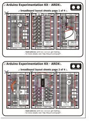
CIRC-11<br />
Breadboard sheet<br />
x1<br />
2 Pin Header<br />
x4<br />
Transistor<br />
P2N2222AG (TO92)<br />
x1<br />
Relay<br />
(DPDT)<br />
x1<br />
2.2k Ohm Resistor<br />
Red-Red-Red<br />
x1<br />
560 Ohm Resistor<br />
Green-Blue-Brown<br />
x2<br />
Green LED<br />
x1<br />
Red LED<br />
x1<br />
Diode<br />
(1N4001)<br />
x1<br />
Schematic:<br />
resistor<br />
(2.2kohm)<br />
Arduino<br />
pin 2<br />
Base<br />
Transistor<br />
P2N2222AG<br />
NO<br />
NC<br />
com<br />
Collector<br />
coil<br />
Emitter<br />
Diode<br />
(flyback)<br />
the transistor will have<br />
P2N2222AG printed on it<br />
(some variations will have<br />
the pin assignment reversed)<br />
+5 volts<br />
gnd<br />
(ground) (-)<br />
The Internet<br />
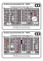
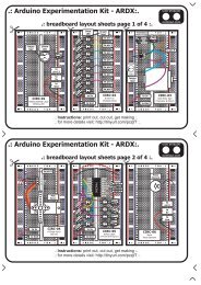
.:download:.<br />
breadboard layout sheet<br />
http://tinyurl.com/cxpvgq.<br />
.:view:.<br />
assembling video<br />
http://tinyurl.com/chf7rx<br />
28