LokSound2 Handbuch, V1.0 Juli 2001 - ESU
LokSound2 Handbuch, V1.0 Juli 2001 - ESU
LokSound2 Handbuch, V1.0 Juli 2001 - ESU

You also want an ePaper? Increase the reach of your titles
YUMPU automatically turns print PDFs into web optimized ePapers that Google loves.
User ManualLokSoundXLVersion 2.1May 2002LokSoundXL User Manual V2.1 05/20021
Characteristics of the LokSoundXL decoderand coreless motors. It may be adjusted to the eachindividual motor. Your locomotive will always keepthe selected speed, no matter how large the load isor whether it is traveling up or down gradients.Eight (!) function outputs: In addition to the twolighting outputs, another six function outputs areavailable for your choice of operation: you mayswitch on smoke generators or interior lighting oruncouple trains by pressing a key at your centralprocessing unit or hand held controller! Withblinking light effects and individually dimmable lampsyour trains look real and give you a lot of enjoyment.Brake tracks: LokSoundXL decoders understand(and react to) all available brake systems: besidesthe Lenz brake generator, Märklin® brake track issupported too.Protecting functions: the motor output as well asall function outputs are protected against overloads.Analogue operation: LokSoundXL decoders maybe operated on AC- and DC systems withoutproblems.Easy programming: Even with Märklin® 6021 allfunctions may be changed easily without openingthe locomotive.•A digital, two-tone sound module with uniquecharacteristics:Prototype sounds: sounds of prototype locomotiveswere sampled using high qualitymicrophones and recorded digitally onto a memorymodule. Thus your locomotives sound as accurateas the prototype!Two channels: in addition to steam impact or dieselsounds, a further sound may be generated at thesame time. Steam whistles, bells, horns, etc. willsound just like the original.Steam, diesel and electric locomotive sounds arepossible: LokSoundXL may imitate every type oflocomotive you may think of. For each type oflocomotive there is a prototypical operationalsequence:Steam locomotive: There are two, three and fourcylindersteam locomotives, whose steam impactsincrease in frequency as the speed of the modellocomotive increases!Diesel locomotive: The engine may be turned onand off and rotates while stationary or driving basedupon the speed of the locomotive! The LokSoundXLdecoder may now also support Diesel electriclocomotives.E-Locomotives: Historical electric locomotivessupply sound effects that are well worth listeningto: from the motion of the pantograph to theclicking and cracking of the switchgear duringacceleration! Even a wheel synchronized squeakingof the brakes is possible!Sounds by pressing a key: Pressing a function key(F1 to F12) emits the sounds!Random noises: Both while stationary and whilemoving, sounds such as air pump, water pump,coal shovels, compressed air discharging, etc. atrandom intervals controlled by you.Chapter 3Connection of the LokSoundXL decoders3.1 Preparing installation of the decoderThe locomotive must be tested for excellent operation:only a locomotive with impeccable mechanicalperformance may take maximum advantage of thedecoder. A locomotive that does not performsmoothly will not operate satisfactorily even with thebest decoder. Replace or clean worn out motor brushes,check wheel contacts, bulbs etc.Remove the locomotive from the track, disconnectand isolate the motor. There must be NO electricalcontact between the motor and the rail pickup.The LokSoundXL decoders have fixed dimensions;make sure, that the decoder fits easily into thelocomotive. Do not use any pressure when replacingthe outer body onto the frame and touch no wires.Further, make certain that flexible parts such astransmissions and trucks are not obstructed by wires.Fasten the decoder inside the locomotive with doublesided tape, hot glue or screws. The decoder gets verywarm during operation. Never pack the <strong>LokSound2</strong>XLdecoder in foam or similar materials. This impedes aircirculation and causes overheating.The LokSoundXL Decoder comes as an opencircuit board that freatly reduces overheating.Handle the LokSoundXL module with care.Electronic components are sensitive toelectrostatic loads: always make sure that yourwork place is grounded. If necessary, use anearthed wristband.4 LokSoundXL User Manual V2.1 05/2002
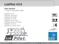
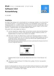
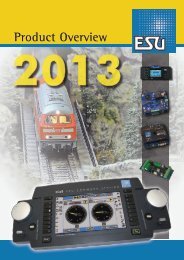
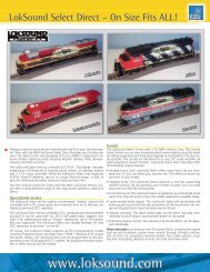
Connecting a DC or coreless motorWhen installing the decoder you must not allowany metal part of the locomotive to touch thesurface components of the decoder.The LokSoundXL module has more connectionsthan common decoders, which are needed forsound generation and function outputs.LokSoundXL comes with two robust terminalblocks to which you can connect the wires ofyour locomotive. Please note when connectingthe wires to the terminals that:LokSoundXL decoder has two terminal block (No.1 and No. 2): make sure you are using the correctterminal block!Make sure that the wire diameter is big enoughfor the terminal (at least 0,20 mm 2 ).Solder the ends of the wires or crimp them.Make sure that no short circuits occur whileconnecting the wires to the terminals.Use a suitable screwdriver.Hold the termimals while turning the screws toavoid pressure on the circuit board.Check every wire for good connection (pull lightlyon the wire).Please check all connections with an ohmmeter.3.2 General circuit diagramFigures 2 and 3 show the general connection schemeof LokSoundXL decoders:The left terminal block (No. 1) has all connections thatare needed for driving- and sound operation. Theright terminal (No. 2) is only needed for functionoutputs.Never mix up those two terminal blocks and alwaysmake sure the connections are correct. If you connectit the wrong way you may destroy the module.Connect right rail to terminal 1-1, connect left rail toterminal 1-2.Use terminals 1-3, 1-4 and 1-6 for the motor. Whenconnecting DC or coreless motors only use terminals1-3 and 1-6. See paragraph 3.3 and 3.4 for furtherdetails.A wheel sensor can be connected to terminals 1-4and 1-5. See chapter 3.9 for more details.Connect the loudspeaker to terminals 1-8 and 1-9.See paragraph 3.6 for installation.Terminal 2 is only for lighting and special functions.Please make sure that all outputs are connected againstterminals 2-9 (positive supply voltage). Please seechapter 3.7 and 3.8 for details.Always install a capacitor of at least 47nF in parallel tothe motor terminals. See figure 1 for an optimalexample of RFI suppression. Please note there areseveral methods of RFI suppression: we recommendto leave any suppressor (e.g. inductors) in thelocomotive.Please check all connections with an ohmmeter,particularly if there are any short circuits betweenmotor- and current pick-ups.3.3 Connecting a DC or coreless motorAlways refer to the general wiring diagram on page 6and bear in mind to keep any inductors connected.For each type of motor (Buehler, Mabuchi, Faulhaber)there are different parameters needed for load control.They have to be adapted to optimize drivingperformance (see chapter 4.2.2).For the motor connection use terminal 1-3 and1-6, terminals in between are not connected.Motor10nF10nFfigure 1: RFI suppression147nF3.4 Connecting a universal motor (AC motor)For easy conversion of older gauge-I locomotives withuniversal motors (AC motor) the motors can bedirectly connected to the LokSoundXL-decoder (seeFigure 4).Connect the two motor terminals to terminals 1-3 aswell as 1-5. Exchanging both wires will changedirection of travel.LokSoundXL User Manual V2.1 05/20025
Connection diagramsDC-MotorRailright left1-11-21-31-41-51-61-71-81-92-12-22-32-42-52-62-72-82-9loudspeakerFigure 2: general wiring diagram6 LokSoundXL User Manual V2.1 05/2002
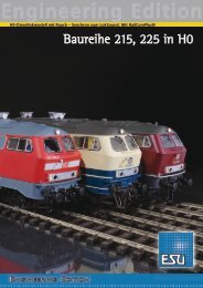
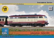
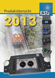
Connection diagrams2-12-22-32-42-52-62-72-82-9Rear lightsHead lightsAUX1AUX2AUX3AUX4AUX5 / Reed-In1AUX6 - Reed-In2common voltage (U+)Figure 3: connecting the auxiliary functionsLokSoundXL User Manual V2.1 05/20027
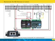
Connecting the speakerThe RFI suppression inductor remains attached to thecollector terminal of the motor. Solder the other oneto terminal 1-4 of the decoder.Universalmotorinductors 3,9 µHloudspeakerRailright left1-11-21-31-41-51-61-71-81-9figure 4: connection to Märklin® Universal motorSolder two inductors with at least 3,9 µH to the motorterminals. You may order these as spare parts fromMärklin® under article number 516520.For optimal operation the motor tact frequency hasto be reduced from 22kHz to 87Hz. To achieve thisset CV 9 to value 204.Please note:If a universal motor is connected, Back EMFControl will be automatically deactivated. Theprinciple of Back EMF Control does not workwith universal motors.The speaker must be installed in such a way that thesound waves are not unduly blocked.Please handle speakers with extreme care: don'tput pressure on or touch the membrane. Thespeaker's magnets are very strong. Keep all metalitems away and secure the speaker firmly whensoldering. The soldering iron may pull the speakerdue the magnetic field and destroy it.Connect the speaker to the twoterminals 1-8 and 1-9 of theLokSoundXL module. Makesure that you use a smallsoldering iron (max. 20 W) andonly heat the marked spot asshown in the figure (close tosolder herethe edge of the small contactplate). Polarity is notimportant. Make sure that no solder is dropped ontothe membrane.An optimal sound effect is achieved by putting thespeaker into a sound chamber, which is supplied withthe speaker.This will increase the soundspeakerpressure and channel thedirection of the sound.Without sound chamber thesound effect may beunsatisfactory. Feedsound chamberthe speaker wiresthrough a small hole inthe sound chamber.3.5 Connecting the speakerThe LokSoundXL decoder may only be used with thespeakers offered by <strong>ESU</strong> electronic solutions ulmGmbH or with speakers with the same data (1 Watt,16 - 32 Ohms). The use of speakers by others maycause considerable distortion and in extreme caseseven destroy the LokSoundXL decoder. We alsocannot recommend speakers that are actually designedfor use with our H0 decoder.The correct position of the speaker is crucial to achievehigh quality sound. A speaker that is installed withouta resonance chamber will not generate good sound.Therefore carefully select the location and soundchamber for the speaker.3.6 Function outputsLokSoundXL decoder has 8 (!) function outputs. Twoare factory-set for directional headlights, the othersix (AUX1 to AUX6) can be used for auxiliary loads.With LokSoundXL you may dim the lamps in 15 stepsto adjust the brightness optimally to your model. Thebrightness of each output may be adjusted separately.See chapter 4.2.4.2. Every function output can beset to various blinking light effects. See chapter4.2.4.3.All function outputs can be individually loaded with0,6A current but cannot exceed a total load of 2,0A.8 LokSoundXL User Manual V2.1 05/2002
Connecting headlightsIf the total current exceeds 2.0A or a short circuitoccurs, then the overload protection switchesoff all function outputs. Once this problem isfixed all outputs are switched back on.3.6.1 Connecting headlightsConnect headlights to terminal 2 as shown in figure3. The light outputs provide the full, rectified trackvoltage (between 14 and 25V depending on the typeof transformer). Therefore only use lamps for yourlocomotive suitable for this voltage.In older style locomotives you may find that lamps areconnected to the chassis. (ie.: Märklin®). In this casedon’t make a connection from the lamp back to theterminal 2-9 and the circuit will be completed via thechassis.LED's or 1,5V-lamps are used in many locomotivesand can be used with LokSoundXL decoders: Use aresistor of about 100 Ohm/0,5 Watt which has to besoldered between function output and lamp, for eachlight output that you want to connect to LED's or1,5V-lamps. Additionally you have to lower thebrightness of the individual function output per CV.See 4.2.4.3.When using 1,5V-lamps it’s not sufficient just toreduce the brightness per CV: for a short momentthe lamp will get the full voltage due to the usedPWM-mechanism.3.6.2 Connecting auxiliary functionsYou can use outputs AUX1 to AUX6 of LokSoundXLdecoders for functions such as operating a smokegenerator, switching lights, Swiss lighting mode etc.Please note that the outputs are used for switching ofresistive loads like lamps, smoke generators, relays.Because of possible voltage peaks due to inductivitydon’t connect the motor directly to the output, usea relay.Each output can be connected to terminal 2-9or to the chassis.Make sure that the sum of all currents for thefunction outputs does not exceed the permittedcurrent rating and avoid short circuits betweenoutputs. Although outputs of LokSoundXLdecoders are protected, high voltage on theterminals or a short circuit may cause damage.LokSoundXL User Manual V2.1 05/20023.7 Connecting a wheel sensorTo synchronize the steam chuff an external sensormay (but does not have to be) used. The sensor inputis terminal 1-7 on the LokSoundXL decoder. TheLokSoundXL decoder supports reed switches ormechanical contacts as well as Hall sensors. In manylocomotives mechanical wheel sensors have been fittedin the factory (e.g. Bachmann or Märklin®).3.7.1 Connecting a reed contact with magnetIf a reed contact is to be used a miniature magnet(available at specialized hobby shops) must be attachedto the driving wheel axle in such a way that the magnetreleases the reed contact once every turn. Miniaturereed switches have been proven to be very reliable.They may be obtained at any electronic specialist store.Suitable magnets may be bought at model train shops.(e.g. Mini-track magnets) which might have to beshaped to fit.Miniature magnetdriving axlereed switchfigure 7: connecting a wheel sensor1-11-21-31-41-51-61-71-81-93.7.2 Connecting a mechanical contactMany locomotives come with a factory fittedmechanical contact that is connected to terminal 1-4and 1-7.All double pole (mechanical) contacts that are isolated(not in contact with the chassis) may be used.3.7.3 Connecting a Hall sensorA Hall sensor is an electronic module that reacts to achanging magnetic field (like the reed switch but more9
Connecting auxiliary reed switchesprecise.) They are easy to install. A commonly usedmodule is the Siemens / Infineon TLE4905 available atelectronic stores.Connect terminal Vs of TLE4905 to terminals 1-4,GMD to terminal 1-4 and Pin Output to terminal 1-7.driving axleMiniature magnetVsGNDOutputTLE49051-11-21-31-41-51-61-71-81-91-11-21-31-41-5Reed switches1-61-7REED-IN11-8REED-IN21-9resistor 10k 0,25Wfigure 9: connecting auxiliary reed switches4. Set Up and installation of the decoderfigure 8: 8 connecting a Hall sensorBefore you can use the wheel sensor certain CVshave to be set. See chapter 5.2.43.7.4 Connecting auxiliary reed switchesAs from version 2.0 the LokSoundXL decoder hastwo additional inputs. You can use them to releasesound effects with the help of trackside magnets.Just connect a reed sensor to the inputs and place amagnet at the appropriate location on the layout.The required sound effect will be activated every timethe locomotive passes the magnet.With the aid if these inputs users of LGB MZS withLokmaus may activate the multitude of sound effectsgenerated by LokSoundXL decoders.Both inputs REED-IN1 and REED-IN2 shareterminal 2-7 as well as 2-8 with function outputsAUX5 and AUX6. If you want to use the REED-IN functions then AUX5 and 6 are not available.Before you can use reed sensors certain CVshave to be set. See chapter 5.2.7After successful installation you may operate thedecoder.But first you will find out how to check yourinstallation. In chapter 4.1 you will find instruction ofhow to operate the decoder in analogue mode. Inchapter 4.2 you learn how to operate it with variousdigital systems.Before changing any decoder settings (e.g. locomotiveaddress, sound volume) we recommend to readchapter 5. There you find out which parameters areavailable and how they may be altered with thecommonly available DCC command centers.After installation you may test the LokSoundXLdecoder as follows.Please inspect all connections carefully using anohmmeter: are there any short circuits betweenthe motor terminals and the wheel pick-ups?Have all connections between motor terminalsand the chassis been isolated? Are bulbsconnected properly and isolated from thechassis? Is the decoder installed safely to avoidcontact with the chassis? Is there sufficient spacearound the LokSoundXL decoder to allow forcooling? Could the LokSound 2 decoder or anyof the wires be squeezed when refitting thehousing? May sound emit from the locomotivewithout obstruction?10 LokSoundXL User Manual V2.1 05/2002
Analogue / digital operationAfter you have checked above points you may switchon the power. We strongly recommend to carry outthis initial test on a track section with overloadprotection. Programming tracks of modern digitalsystems offer this protection. Our LokProgrammeralso offers extremely reliable overload protection.•The pre-set locomotive address is 03.•Does the locomotive travel in both directions?•Turn the lights on: are they operating correctly?•You activate sound by pressing function key F1,either the Diesel starts or you hear steam sounds.When pressing function key F2 you should hear thehorn, whistle or bell, etc.4.1 Analogue operation4.1.1 DC OperationDC operation using a conventional controller is possiblewithout any problems but has one limitation. Thelocomotive will only start moving when the trackvoltage reaches7-8V.Maximum speed will be reachedwhen turning the controller to the limit. This isabsolutely normal and is due to the minimum voltagethe LokSoundXL decoder requires for operation.As factory default, sound effects cannot be activatedin DC operation.4.1.2 AC operation with conventionalMärklin® controllerOperation with conventional Märklin® controllersworks as usual: speed is controlled by turning theknob.To change direction the knob has to be turned to theleft beyond the stop position.Please note:The locomotive must have completely stoppedbefore changing direction. Never changedirection of a moving locomotive!Press the knob slightly longer than usual (about0,5 sec) in order to activate the command reliably.As factory default, sound effects cannot be used withthis type of operation.LokSoundXL User Manual V2.1 05/20024.2 Digital operation4.2.1 Using Märklin® 6021The LokSoundXL decoder may be used with allMärklin® products or compatible systems.The functions F1 to F4 can only be activated with the"New Motorola Format". To activate this format putthe DIP switches 1 and 2 of the 6021 to the upper("On") position.4.2.2 With DCC (Lenz, Intellibox, etc)Remove capacitors that may be connected tothe track section (e.g. in ROCO connecting track).They may impede normal operation of thedecoder.LokSoundXL can be run with any system that conformsto DCC. The automatic speed step detection has beentested with the following appliances: ROCO Lokmaus2, Uhlenbrock Intellibox, Lenz Digital plus V2.3, ZIMOMX1.The detection does not work properly whenoperated with Lenz Digital plus V3.0 if you wishto run 14 speed steps. Use 28/128 speed steps.Each time that the LokSoundXL decoder receives acurrent (i.e. after the system is switched on) and thelight is switched on it tries to detect the speed stepssettings. If you switchover the speed steps settingsduring operation you must briefly switch off thecurrent supply to the decoder so that the automaticmode functions as desired. The detection takes up to30 seconds.The detection can be switched off using CV 49 (pleaserefer to section 7.1).Operation with LGB Multi Train System (MTS)LokSoundXL decoders also support the LGB CommandControl system. Both Lok-Mouse and Lok-Handy maybe used, but they have to be activated first.LGB does not utilize the function keys specified in theDCC standards but has designed a procedure based11
Adjusting decoder parameterson multiple pressing of the F1 button: e.g. if youpress F1 three times this will activate function F3.Therefore it is essential to “tell” the decoder, that ithas to count how often the F1 button makes contact.By setting bit 6 in CV 49 the LokSoundXL decoder willsupport the LGB operating mode.Let’s assume you want to use LGB MZS and activateload control as well. Simply enter the value 65 in CV49.5. Adjusting decoder parametersChapter 5 provides information on how to changethe settings of LokSoundXL decoders. Please take yourtime to read and understand the occasionallysomewhat complex explanations.After the introduction into the world of decoderparameters (called CVs) in chapter 5.1, you will find allyou want to know about which CVs have effect theproperties of LokSoundXL decoders in chapter 5.2.Paragraph 5.3 explains how CVs may be set with variousDCC and also the Märklin® command stations.You find a complete list of all CVs in chapter 7.1.5.1 CVs of the LokSoundXL decodersLokSoundXL decoders are compatible with the NRMA/ DCC standard. That means, that all parameters whichchange the properties of LokSoundXL decoders, arestored in so called CVs (Configuration Variables).LokSoundXL decoders support 121 variables. This largenumber of CVs shows the multitude of possibilitiesavailable with LokSoundXL decodersTo manage this large number of settings werecommend the use of our LokProgrammer. WithLokProgrammer all CVs may be programmed withease and comfort by using a PC. Please note that CVsthat are not programmed properly could impede theperformance of the decoder.All CVs may be programmed without theLokProgrammer by using any DCC system that isNMRA/DCC compatible. Märklin® 6021 is alsosuitable. Chapter 5.3 explains, how it works.In each CV values from 0 to 255 may be stored. Theproperties of the decoder change depending on thestored value.If you have a look at the list of CVs in chapter 7.1 youwill notice that most CVs have number values. CV 1for example contains the locomotive address. This mayvary between 1 and 127 (see range of values). Thefactory setting is 3. Please note that not all CVs havefactory settings. Some CV values are different fordifferent sound effects.Other CVs represent storage locations that managevarious functions at the same time (mostly turn onand off). CVs 29 and 49 are good examples: for theseCVs the value has to be calculated individually,depending on the setting you want:First you decide which option should to be turned onor off. In the column "value" you find 2 numbers foreach option. The value 0 indicates the option is switchedoff, otherwise the value may range from 1 to 32. Addall values of the individual options to get the value ofthe CV.Example 1: 1 Let's assume, you want to use theIntellibox DCC with 128 speed steps and analoguerecognition should be active (because you want tocontrol some locos analogue mode). All otheroptions are turned off. CV 29 shows the value 6 (0+2+4+0=6).Example2: You want to activate the Märklin®brake module, Back EMF should be activated. YousetCV49to3(1+2+0=3).Werecommend todeactivate analogue recognition in CV 49, since theMärklin® brake track and analogue operation shouldnot be activated at the same time. You set CV 29 to0(0+0+0+0)=0.Example3: You want to turn the volume of thedecoder down. Set CV 63 to 1.5.2 Important settings of LokSoundXLDetails of the most important CVs may be found inchapter 5.2. Please study these instructions carefullybefore you do any program changes. Carefuldeliberation will help you to find the optimal settingsto achieve the desired effects with your LokSoundXLdecoder.5.2.1 Back EMF control (load control)The LokSoundXL decoders utilize second generationload control which, when using DC motors, assuresconstant speed independent of the actual load. Load12 LokSoundXL User Manual V2.1 05/2002
Fig. 12 Function Mapping as per NMRA / DCCFunction keyDescriptionControl-CVOutput "light forward"Output "light rear"Output AUX1Output AUX2Soundslot 1Soundslot 2AUX3 / Soundslot 3AUX4 / Soundslot 4AUX5 / Soundslot 5AUX6 / Soundslot 6Soundslot 7Soundslot 8Acceleration on / offSound on / offF0 Light forward #33 1 • 2 4 • 64 128 16 32F0 Light reverse #34 1 2 • 4 • 64 128 16 32F1 Key F1 #35 1 2 4 64 128 16 32•F2 Key F2 #36 1 2 4 64 • 128 16 32F3 Key F3 #37 1 16 32• 64 128 4 8F4 Key F4 #38 1 16 32 64 • 128 4 8F5 Key F5 #39 1 16 32 64 128 • 4 8F6 Key F6 #40 1 16 32 64 128 4 • 8F7 Key F7 #41 1 2 4 8 16 • 32 64 128F8 Key F8 #42 1 2 4 8 16 32 • 64 128F9 Key F9 (F) #43 1 2 4 8 16 32 64 128F9 Key F9 (R) #47 1 2 4 8 16 32 64 128F10 Key F10 (F) #44 1 2 4 8 16 32 64 128F10 Key F10(R) #48 1 2 4 8 16 32 64 128F11 Key F11 #45 1 2 4 8 16 32 64 128F12 Key F12 #46 1 2 4 8 16 32 64 128LokSoundXL User Manual V2.1 05/200215
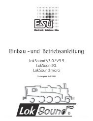
Diming the lamps•Dimmer: normal, continuously switched on load•Blinking light: the output blinks with an adjustablefrequency•Blinking light inverse: the output blinks as usualbut in opposite sequence.This permits to activateblinking lights in opposite sequence (lamp1=on,while lamp 2 = off and vice versa).Starting with CV 114 each output has a CV that youcan program with the desired mode. Please note thatyou may deactivate each output with "0" if not needed.The light outputs are factory pre-set to "on". Allother function outputs AUX1 to AUX6 may beswitched off by factory default, depending onthe type of LokSoundXL-Decoder.Dimming of lampsWith LokSoundXL you may dim the lamps in 15 stepsto adjust the brightness optimally to your model. Thelamps are pulsed, i.e.: they are continuously switchedon and off. The brightness of each output may beadjusted separately. The desired dimming value (0 to15) has to be added to the value of the correspondingControl-CV (113 to 120) that defines the functionmode.Blinking frequency and duration of "brightphase"If a function output has been set to "blinking" or"blinking inverse", the duration of the "bright period"(defines blinking frequency) and the on / off ratiohave to be taken from CV 121 (see paragraph 7.1).The "bright period" is adjustable in 16 steps. It is alwaysa multiple of 0,184 sec.The On / Off ratio is adjustable in 16 steps from 1/16to 16/16. A ratio of 8/16 indicates that the lightoutput remains "on" for the same period as it is "off".The value to be entered into the Control-CV 121 iscalculated as follows:Duration of "On" period (value: 0-15)*16+On/Off ratioExamples:•Example 1: smoke generator at AUX1 and F5.Let's assume you want to control a smoke generatorwith function key F5 that should be connected tooutput AUX1. Please refer to the installationinstructions in chapter 2.5. The output AUX1 mustbe activated and assigned to the F5 key:First we activate the output. In this example wewant to use the dimming function (the output mustbe active continuously) and set at 100% brightness.CV 115 controls output AUX1 (see paragraph 7.1).The value to be entered into CV 115 is calculated asfollows: 16 (for dimming function) + 15 (formaximum brightness) = 31.Now we have to assign function key F5 to outputAUX1: see figure 12: Control-CV 39 controls theF5 key (third column). In CV 39 we enter thosefunctions that should be switched with the F5-key.We look at the table in figure 12, locate theintersection of the row for F5 and column AUX1and find the number (in this case 1). Once we enterthis value in CV 39 the F5key controls the outputAUX1.•Example 2: blinking light at AUX6 and F8We want to connect a “blinking light” to AUX6 andcontrol it via the F8 function key. The brightnessshould be set to 6/15 of the maximum value. The“bright period” and the “on / off” ratio are set asdescribed beforeFirst we have to activate output AUX6 and set it to“blinking”. We achieve this by entering 32 (forblinking) +5(=6/15 of maximum brightness) =37 in CV 120.Next we assign output AUX6 to the F8 key. Weenter the functions to be controlled via F8 into CV42. Again we consult the table in figure 12, findthe intersection between row F8 and column AUX6and enter the number from the table in CV 42 (inthis case 32). Now the F8 key controls the outputAUX6Please note that sound slot 6 and AUX6 outputare coupled: both the blinking light and sound,memorized in sound slot 6, are activated and caneasily be modified using the LokProgrammer anda PC.•Example 3: Deceleration on / off with F5Here we want to activate / deactivate theacceleration/deceleration with F5. This functionrepresents a "logical" function and not a "physical"output and thus does not have to be configured.We only have to assign function "deactivatedeceleration" to the F5 key by entering value 4 inCV 39 (see figure 12)16 LokSoundXL User Manual V2.1 05/2002
Sound adaptionWe recommend a PC and LokProgrammer forprogramming function outputs: the LoksoundXL-Decoder offers so many possible combinations that itis difficult to manage these without a computer.5.2.4 Sound adaptationLokSoundXL decoders offer many possibilities to adjustthe sound effects. All parameters are stored in CVsthat, like all others, may be modified.Adaptation of revolutions for diesel and pitch forsteamThe revolutions of a diesel motor may be modifiedwith 2 CVs:•Enter the revolutions of the idling diesel motor inCV 50. The standard value of 128 permitsreproduction of the sound at original speed, whilevalue 64 reduces this to half speed.•Enter the revolutions at maximum speed in CV 51:value 255 means double the original speed.Use the same parameters when adapting the pitch ofthe chuffs for steam locomotives: the interval of thechuffs should be shorter and vary in pitch withincreasing speed.Settings for diesel or electric locomotivesTo simulate a diesel or electric locomotive the CVs 52and 53 have to be set to 0.Special settings for steam locomotivesTo simulate a steam locomotive you have tosynchronize the steam chuffs with the revolutions ofthe driving wheels. There are 2 ways:•With an external wheel sensor•Speed step dependentDepending on the method selected, certain CVs haveto be set accordingly. LokSoundXL is factory pre-setto speed step depend adjustment.Using the wheel sensorThe wheel sensor must be connected as described inchapter 3.7.3 Then two more settings have to bedone: set CV 52 to value 255 and enter a value > =1in CV 53. CV 53 defines after how many pulses by theLokSoundXL User Manual V2.1 05/2002sensor the next steam chuff will be reproduced.Normally one chuff per pulse should be played,therefore CV 53 should read "1".Speed step dependent methodWith this method the interval between chuffs is setwith CV 52 and CV 53. This method is recommendedif an external wheel sensor cannot be used. Theadaptation of this variable to the combination of wheel/ gearbox may require some tests. It pays to spendsome time in order to achieve an optimal result. Thisfeature works best with Back EMF control. WithMärklin® locomotives with universal motor (Back EMFis always switched off) only a compromise may bereached. In this case we recommend the use of anexternal wheel sensor.For CV adaptation proceed as follows:•Set CV 52 to 100 and CV 53 to 200.•Put the locomotive onto the track and drive withspeed step 1 (sound is switched on).•Measure the time it takes in seconds for the drivingwheel to do one turn at this speed.• Divide the time by 0,04608.•Enter a rounded value without decimal points in CV52.•Increase the speed and check whether the chuffrhythmmatches the turns of the drivers. If thechuff is too fast, increase the value in CV 53gradually, if it is too slow, decrease the value inCV 53.Adjusting the volumeThe volume of LokSoundXL decoders may be adaptedin 3 steps:Enter the desired value in CV 63.Permitted values are: 0 (quiet), 1 (medium), 2 (loud).Random sound effectsCV 54 and CV 55 define the frequency of randomsounds that are played while a steam locomotive isstationary. CV 54 contains the minimal time between2 random sounds, CV 55 the maximum. Bothrepresent an interval in which LokSoundXL randomlyselects and plays sounds. The units of both CVs are0.184 seconds.Example: the minimum interval in CV 54 should be1.5 seconds. Enter 1.5 / 0.184 = 8 into CV 54.17
Brake sections / Reed switch inputs5.2.5 Brake sectionsThe LokSoundXL decoder responds to the two mostcommonly used brake generators, which are:•Lenz and ROCO brake generators in DCC operation•Märklin® brake trackAs soon as the LokSoundXL decoder recognizes abrake command it brakes with a deceleration, whichmay be set independently. After this forced stop thelocomotive begins to move again and accelerates tothe previously set speed. The acceleration may beprogrammed separately from the standard acceleration/ deceleration value (CV 61 and CV 62).This feature is activated in CV 49.Lenz LG100 / ROCO 10763No settings are required. Both brake generators usethe mechanisms recommended by the NMRAstandards. They are always supported by LokSoundXLdecoders. n.Märklin® brake trackInstead of digital signals the Märklin® brake tracksupplies a DC voltage to the tracks. To activate thisyou must set bit 1 in CV 49.Do not activate the Märklin® brake track andthe analogue DC operation at the same time,because the DC of the Märklin® brake track couldbe interpreted as analogue DC operation. WithCV 29 you may switch off the analogue mode(see paragraph 7.1).5.2.7 Reed switch inputs*** new for version 2.0 ***In order to activate special sound effects two inputsmay be connected to reed contacts.Typically this would be used to activate sound effectswithout using the command control station. If youinstall a magnet at a level crossing and a reed switchonthe locomotive chassis, it is possible to configure theLokSoundXL decoder in such a way that every timethe locomotive passes the crossing the whistle will beactivated.How to connect these reed contacts has beendescribed in section 3.7.4. The following explains howto set the decoder for this application.The inputs REED-IN1 and REED-IN2 share theterminals 2-7 and 2-8 with AUX5 and AUX6. Thereforeyou can only use either the inputs or the outputs butnot both at the same time.These inputs work as follows: If a contact is closed (bya magnet) then the effect is the same as if a functionkey had been pressed. For REED-IN1 this may be F5or F9, for REED-IN2 it could be F6 or F10.The effect you have set to be activated by therespective function key will now also be activated bythe reed contact. How to allocate certain functionsto specific function keys is described in section 5.2.3.To activate REED-IN1 and REED-IN2 use CV 119 and120. Depending on which function key should activatewhich input the appropriate value has to be enteredin the CVs.:Input Key Control-CV ValueREED-IN1 F5 CV 119 14REED-IN1 F9 CV 119 15REED-IN2 F6 CV 120 14REED-IN2 F10 CV 120 15Fig. 13: Values for CV 119 and CV 120Examples:Let’s assume, you want to activate a whistle via REED-IN1. The appropriate sound is stored in sound slot 1.This simulates pressing the function key F5.Enter 14 in CV 119. Then allocate the whistle (soundslot 1) to function key F5 (respectively to REED-IN1).CV 39 controls F5 (refer to fig. 12 on page 26). Toactivate sound slot 1 set CV 39 to 16.Let’s assume, you want to activate the bell via REED-IN2. This sound effect is stored in sound slot 2. Thissimulates pressing function key F6.Enter 14 in CV 120. Then allocate the bell (sound slot2) to function key F6 (respectively to REED-IN2). CV40 controls F6. To activate sound slot 2 set CV 40 to32.18 LokSoundXL User Manual V2.1 05/2002
Adjusting CV’s using DCC systems5.3 Adjusting CVsAfter having been introduced to the effects controlledby CVs in paragraph 5.1 and 5.2 we now need toclarify how to set the CVs. There are 3 possibilities:•With a PC and LokProgrammer•With a DCC compatible digital command station(e.g. Intellibox, Lenz digital plus)•With Märklin® 6021Depending on the product used the procedure varies.•Programming is not possible. The Lenz commandstation displays "err02", the Arnold commandstation "short circuit":This is caused by the overload protection of the digitalsystem, which is very sensitive. The LokSoundXLdecoder with the built in audio amplifier uses a highercurrent than other decoders and thus activates theoverload protection of the systems. To rectify this,solder a resistor with 47 ohm (0,5 Watt) in one of thetwo wires, connecting the digital command stationwith the programming track. See figure 13.5.3.1 Using LokProgrammerThe LokProgrammer by <strong>ESU</strong> electronic solutions ulmGmbH offers the easiest method to modify CVs of allLokSound decoders: with a click of the mouse usingMS-Windows®. The PC helps you to find the variousCV numbers and values. With the LokProgrammeryou can also modify the sound effects of LokSoundXLdecoders and you may create your own sound effects.You may purchase the LokProgrammer at Model Trainoutlets complete with detailed operating instructions.Programming trackcommand stationResistor 47Ω5.3.2 Using DCC systemsThere is no "one fits all" instruction for programmingof CVs with various DCC systems. There are too manydifferences between the popular DCC systems.Whenever possible you should use the DCC direct mode(CV programming by setting individual bytes withUhlenbrock) or DCC paged mode.Refer to chapter 9 "programming" of the user manualfor the Intellibox. In particular read chapter 9.5"programming of DCC decoders" very carefully.Programming should be done in the "CV-programmingbyte-wise" mode.Lenz digital plusThere are various software versions available of theLenz digital plus command station. You need firmwareversion 2.3 or higher in order to program LokSoundXLdecoders. Contact Lenz for more details regardingupgrades of older versions.Use "paged CV" mode for programming.Depending on the firmware version the "CVmode" might cause problems.Older command stations such as "Digital plus", "Lenzcompact" and "Arnold Digital" create anotherphenomenon:LokSoundXL User Manual V2.1 05/2002Fig. 14: Lenz command station with 47Ω resistor5.3.3 Using Märklin® 6021With the Märklin® command station you cannotmodify standard CVs as it does not comply with theNMRA DCC standards. However, the most importantCVs of LokSoundXL decoders may be changed with aspecific programming mode, described as follows:You cannot program the 6021 with the CV conceptbecause only values from 01 to 80 may be enteredwith this command station. That's why we call values,which may be modified with the 6021 "registers". Eachof the 64 registers responds to a DCC standard CV.Figure 14 shows a list of the register numbers andtheir CV numbers.If you want to change a certain CV you have to lookup the register number first in figure 14 and thenmodify it.Many CVs have three digit values, however, the 6021only allows a two digit input. The LokSoundXL decoderovercomes this problem by multiplying the enteredvalue with a factor. The result will be memorizedinternally. See figure 14for the appropriate multiplier.That means that not all functions of the LokSoundXLdecoder may be adjusted with Märklin® commandstations.19
Adjusting CV’s using Märklin® 6021Programming mode of 6021Set decoder into programming mode before enteringany changes with the 6021. Only then may the registerbe selected and the new value entered and confirmed.Once you have modified all parameters you want tochange, exit the programming mode with register"80".Peep sounds, varying in pitch and length, indicatewhich mode you are currently using. That keeps youin control:Peep sounds, varying in pitch and length, indicate thevarious modes of LokSoundXL decoder:a) Register input mode (01 to 64 or 80)• • • (short, low tones, long intervals)b) value input mode (01 to 80)•• •• •• (combination from long / shorttones, high frequency)c) Confirmation(long, high tone)Make sure that not only the track- and motorconnections are installed properly but also the speaker,since the speaker provides the acoustic signals.•The regulator must be set to 0.•Take all other locomotives off the track.•Listen to the sound signals of the locomotive.To get into programming mode:•Press the "stop" and "go" keys simultaneously on6021 to activate a reset (or pull the plug of thepower pack).•To switch off the track voltage, press the "stop" key.•Enter the current decoder address (alternative "80").•Activate the change of direction feature (turn thecontrol knob far left until you hear a "click"), holdthe knob in position and press the "go"-key.•The LoksoundXL decoder is now in register inputmode.•Enter the register number you want to change.Make sure you always enter a two digit number(e.g. "01" and not "1")•To confirm any entry turn the knob far left (changeof direction feature). The decoder is now in valueinput mode.•Now enter a new value for the register as a twodigit number. Bear in mind that this value ismultiplied with the factor given for each register infigure 11.Note that you may only enter values 01 to 80with the 6021. Value "0" is missing, enter instead"80".•Turn the knob far left to confirm. You hear a long,high tone.RegisterCVCVFig.14 register values for 6021descriptionmultiplicator01 64 Märklin Address 102 2 VStart 103 6 VMid 404 5 VHigh 405 3 Acceleration rate 106 4 Deceleration rate 107 61 Acceleration rate signal section 108 62 Deceleration rate signal section 109 57 Load control parameter K 410 58 Load control parameter I 411 50 Sound Speed Min 412 51 Sound Speed Max 413 52 Sound Steam 1 (chuff) 414 53 Sound Steam 2 (chuff) 415 63 Volume (Speaker) 116 9 Motor PWM 117 56 Regulation reference 418 11 Packet Time-Out 419 60 Analogue VStart 120 13 Analogue Function status 1 121 14 Analogue Function status 2 122 29 Configuration data 123 49 Control data 124 33 Output location FL(f) 125 34 Output location FL(r) 126 35 Output location F1 127 36 Output location F2 128 37 Output location F3 129 38 Output location F4 130 66 Forward trim 131 95 Reverse trim 160 112 Braking sound Level 161 121 Flash light 162 - 64113-115Output Config Light - AUX 180 End of programming mode20 LokSoundXL User Manual V2.1 05/2002
Frequently asked questions (FAQ)•The LokSoundXL decoder changes again toregister input mode. Enter further CVs you wantto modify.•Exit the programming mode by selecting register"80" or switch the track voltage off and on (press"stop"-key and then "go"-key on 6021).6. Frequently asked questions (FAQ)There could be many reasons if the LokSoundXLdecoder does not work properly after installation.Frequently there is no defect, only the various settingsdo not correspond with the respective locomotive.We list some symptoms and how to solve them:„Lighting / sound / read and write CVs works, butthe locomotive does not move.“•A short circuit in the motor or a high current drawhas released the overload protection of LokSoundXLdecoder.•The motor may not be isolated from the chassis. Inthis case remove the motor but do not disconnectit and test the LokSoundXL decoder.•Set the motor takt frequency from 22 kHz to 87Hz when using universal motors (see CV 9).„The locomotive jerks and does not run smoothly atlow speed when Back EMF control is activated.“•Check if the symptoms persist when you deactivateBack EMF control (see chapter 5.2.1). If so, adjustthe motor control parameters (see 5.2.1)•Possibly the motor has not been isolated againstthe chassis. To eliminate this particular problem firstremove the motor and then test it. If it works youhave identified the cause of the problem.Make sure there is no electrical contact betweenthe motor and chassis when you reinstall the motor.This is particularly important with older motors fromMärklin® (ie: class 78).„The locomotive runs, but there are no sounds.“•Check the wiring to the speaker.•The F1 key works only with the new Motorolaformat when using Märklin® 6021 (see chapter4.2.1). If this is ok, there may be damage to thespeaker.„I would like to reset the LokSoundXL decoder tofactory settings. How does it work?“•This is not an easy task because the factory settingsvary depending on the purchased sound version.However, for most CV’s, a default value is given inLokSoundXL User Manual V2.1 05/2002the table found in chapter 7.1•A decoder-reset is easily possible with a PC and theLokProgrammer software.„After installing the LokSoundXL decoder thelocomotive moves in one direction at max speedwhile it remains stationary in the opposite direction!?“•This is caused by an incorrect motor connection.Please refer to Fig. 2 and 4. Has the motor beenconnected to the right terminals? They are notlocated adjacent to each other, there may be inputsor outputs in between.I have installed LokSoundXL decoders in my LGBlocomotives. Why do functions F2 and higher notrespond when activated with the LGB-Lokhandy?•This problem is typical for the LGB command stationand is not related to our decoder. If you press F5for instance, then the Lokhandy transmits five timesF1 on, F1 off, F1 on, etc. The LGB decoders countthese pulses and subsequently switch the requiredfunction output.•LokSoundXL decoders can „count“ these pulses,but you need to enable this function first. Seesection 4.2.2 for further details.„I have studied the manual, but there are stillproblems. What can I do?“•If you have further questions don't hesitate tocontact our service department. Contact details arelisted in chapter 8, on the last page of this manual.•If you have studied this manual but feel you don'twant to proceed with the installation, esu electronicsolutions ulm GmbH can offer professional help:Enquire at your local hobby store for the LokSoundservice pack: we install the decoder for you.(available in Germany only)7. Appendix7.1 List of all supported CVsOn the following pages you will find tables with allexisting CVs.Read about the CV concept in chapter 5.1.Change CVs only if you have a clear understandingof the implications. Wrong settings may damagethe LokSoundXL decoder21
List of all supported CVsCV namedescriptionrangedefault1 Locomotive address Address of locomotive 1 - 119 32 Start voltage Sets the minimum speed of the locomotive 0 - 255 33 Acceleration This value multiplied by 0.869 is the time 0 - 63 4from stop to maximum speed4 Deceleration This value multiplied by 0.869 is the time 0 - 63 3from maximum speed to stop5 Maximum speed Maximum speed of locomotive 0 - 255 636 Vmid Medium speed of locomotive 0 - 255 257 Version number Internal software version of LokSoundXL decoder - -8 Manufacturer's ID Manufacturer's version number (ID) of <strong>ESU</strong> - 1519 PWM period Duration of PWM signal for motor control 0, 204 0functionvaluePWM frequency = 22000 Hz (recommended) 0PWM frequency = 87 Hz (for universal motors) 20411 Paket timeout time This value multiplied by 0.36864 is the time 0 - 255 0after which the locomotive stops if no DCC packet isreceived.Switch off with value 0.13 Analogue mode F1-F8 Status of functions F1 to F8 in analogue mode. 0-255 0Bit FunctionValue0 Function F1 11 Function F2 22 Function F3 43 Function F4 84 Function F5 165 Function F6 326 Function F7 647 Function F8 12814 Analogue mode FL, Status of functions FL, F9 bis F12 in analogue mode. 0-255 3F9-F12Bit FunctionValue0 Function FL(f) 11 Function FL(r) 22 Function F9(f) 43 Function F10(f) 84 Function F11 165 Function F12 326 Function F9(r) 647 Function F10(r) 12822 LokSoundXL User Manual V2.1 05/2002
List of all supported CVsCV namedescriptionrangedefault17 Extended long address of locomotive 128 - 018 locomotive address CV 17 contains byte with higher value (Bit 6 and 9999Bit 7 must always be active), CV18 containsbyte with lower value. Only active when functionin CV 29 is switched on. (see below)19 Consist address Additional address for consist 0 - 127 0value 0 means: consist address deactivated23 Acceleration Additional period of acceleration which is added 0 - 255 0adaptation to or deducted from the base value (CV 3)values from 0 - 127 are added to the base value,values > 128 are deducted.Mathematical: bit 0-6 represents the value,bit 7 indicates plus (0) or minus (1)(see DCC Standards)24 Deceleration Additional period of deceleration, which is added 0 - 255 0adaptation to or deducted from the base value (CV 4)values from 0 - 127 are added to the base value,values > 128 are deducted.Mathematical: bit 0-6 represents the value,bit 7 indicates plus (0) or minus (1)(see DCC Standards)29 Configuration register The most complex CV within the DCC standards. - 4This register contains important information,which is only relevant in DCC operation.Bit functionvalue0 Reverse direction of travel(forward becomes reverse)normal direction 0reversed direction 11 speed steps (only for DCC operation)14 speed steps 028 or 128 speed steps 22 analogue operationanalogue operation switched off 0analogue operation permitted 44 selection of speed curvespeed curve through CV 2,5, 6 0speed curve through CV 67 - 96 165 selection of locoaddress (only for DCC operation)short addresses (CV 1) in DCC operation 0long addresses (CV 17 + 18) in DCC operation 32LokSoundXL User Manual V2.1 05/200223
List of all supported CVsCV namedescriptionrangedefault33 Function- Assignment of function outputs, which are activated 0 - 255 1assignmentFL(f) with the "light" function (f) when driving forwardBit descriptionvalue0 light output forward 11 light output rear 22 function output AUX1 43 function output AUX2 84 acceleration / deceleration off 165 sound on / off 326 sound slot 1 647 sound slot 2 12834 Function- Assignment of function outputs which are activated 0 - 255 2assignmentFL(r) with the "light" function (f) when driving backwardsBit descriptionvalue0 light output forward 11 light output rear 22 function output AUX1 43 function output AUX2 84 acceleration / deceleration off 165 sound on / off 326 sound slot 1 647 sound slot 2 12835 Function Assignment of function outputs, which are 0 - 255 32assignmentF1 activated with function key F1Bit descriptionvalue0 light output forward 11 light output rear 22 function output AUX1 433 function output AUX2 84 acceleration / deceleration off 165 sound on / off 326 sound slot 1 647 sound slot 2 12824 LokSoundXL User Manual V2.1 05/2002
List of all supported CVsCV namedescriptionrangedefault36 Function Assignment of function outputs, which are 0 - 255 64assignment F2 activated with function key F2Bit descriptionvalue0 light output forward 11 light output rear 22 function output AUX1 43 function output AUX2 84 acceleration / deceleration off 165 sound on / off 326 sound slot 1 647 function output AUX4 / sound slot 2 12837 Function Assignment of function outputs, which are 0 - 255 32assignment F3 activated with function key F3Bit descriptionvalue0 function output AUX1 11 function output AUX2 22 acceleration / deceleration off 43 sound on / off 84 sound slot 1 165 sound slot 2 326 function output AUX3 / sound slot 3 647 function output AUX4 / sound slot 4 12838 Function Assignment of function outputs, which are 0 - 255 64assignment F4 activated with function key F4Bit descriptionvalue0 function output AUX1 11 function output AUX2 22 acceleration / deceleration off 43 sound on / off 84 sound slot 1 165 sound slot 2 326 function output AUX3 / sound slot 3 647 function output AUX4 / sound slot 4 128LokSoundXL User Manual V2.1 05/200225
List of all supported CVsCV namedescriptionrangedefault39 Function Assignment of function outputs, which are 0 - 255 0assignment F5 activated with function key F5Bit descriptionvalue0 function output AUX1 11 function output AUX2 22 acceleration / deceleration off 43 sound on / off 84 sound slot 1 165 sound slot 2 326 function output AUX3 / sound slot 3 647 function output AUX4 / sound slot 4 12840 Function Assignment of function outputs, which are 0 - 255 0assignment F6 activated with function key F6Bit descriptionvalue0 function output AUX1 11 function output AUX2 22 acceleration / deceleration off 43 sound on / off 84 sound slot 1 165 sound slot 2 326 function output AUX3 / sound slot 3 647 function output AUX4 / sound slot 4 12841 Function Assignment of function outputs, which are 0 - 255 0assignment F7 activated with function key F7Bit descriptionvalue0 sound slot 1 11 sound slot 2 22 function output AUX3 / sound slot 3 43 function output AUX4 / sound slot 4 84 function output AUX5 165 function output AUX6 326 sound slot 7 647 sound slot 8 12826 LokSoundXL User Manual V2.1 05/2002
List of all supported CVsCV namedescriptionrangedefault42 Function Assignment of function outputs, which are 0 - 255 0assignment F8 activated with function key F8Bit descriptionvalue0 sound slot 1 11 sound slot 2 22 function output AUX3 / sound slot 3 43 function output AUX4 / sound slot 4 84 function output AUX5 165 function output AUX6 326 sound slot 7 647 sound slot 8 12843 Function Assignment of function outputs, which are 0 - 255 0assignment F9(f) activated with function key F9 when driving forwardBit descriptionvalue0 sound slot 1 11 sound slot 2 22 function output AUX3 / sound slot 3 43 function output AUX4 / sound slot 4 84 function output AUX5 165 function output AUX6 326 sound slot 7 647 sound slot 8 12844 Function Assignment of function outputs, which are 0 - 255 0assignment F10(f) activated with function key F10Bit descriptionvalue0 sound slot 1 11 sound slot 2 22 function output AUX3 / sound slot 3 43 function output AUX4 / sound slot 4 84 function output AUX5 165 function output AUX6 326 sound slot 7 647 sound slot 8 128LokSoundXL User Manual V2.1 05/200227
List of all supported CVsCV namedescriptionrangedefault45 Function Assignment of function outputs, which are 0 - 255 0assignment F11 activated with function key F11Bit descriptionvalue0 sound slot 1 11 sound slot 2 22 function output AUX3 / sound slot 3 43 function output AUX4 / sound slot 4 84 function output AUX5 165 function output AUX6 326 sound slot 7 647 sound slot 8 12846 Function Assignment of function outputs, which are 0 - 255 0assignment F12 activated with function key F12Bit descriptionvalue0 sound slot 1 11 sound slot 2 22 function output AUX3 / sound slot 3 43 function output AUX4 / sound slot 4 84 function output AUX5 165 function output AUX6 326 sound slot 7 647 sound slot 8 12812847 Function Assignment of function outputs, which are 0 - 255 0assignment F9(r) activated with function key F9 when driving backwardsBit descriptionvalue0 sound slot 1 11 sound slot 2 22 function output AUX3 / sound slot 3 43 function output AUX4 / sound slot 4 84 function output AUX5 165 function output AUX6 326 sound slot 7 647 sound slot 8 12828 LokSoundXL User Manual V2.1 05/2002
List of all supported CVsCV namedescriptionrangedefault48 Function Assignment of function outputs, which are 0 - 255 0assignment F10(r) activated with function key F9 when driving backwardsBit descriptionvalue0 sound slot 1 11 sound slot 2 22 function output AUX3 / sound slot 3 43 function output AUX4 / sound slot 4 84 function output AUX5 165 function output AUX6 326 sound slot 7 647 sound slot 8 12849 Extended Activate support for brake track sections 5configuration or switch off Back EMF controlBit descriptionvalue0 load control activated 11 Märklin brake track activated 23 DCC Automatic Speed Step Detection activated 324 function key interpretation according to 64LGB MTS System50 Sound Min Divided by 128 this will yield the factor for 0 - 255 128reproducing the sound at the slowest speed step.values < 128 are slower, values > 128 arefaster than original speed51 Sound Max Divided by 128 this will yield the factor for 0 - 255 128reproducing the sound at the fastest speed step.values < 128 are slower, values > 128 arefaster than original speed52 Sound mode 1 Multiplied by 0,04608 is the time in seconds 0 - 255 steam: 90between two chuff sounds at speed step 1 diesel: 0value 0 deactivates steam sound electric: 0and changes to diesel soundvalue 255 indicates that period between chuffs iscontrolled by a wheel sensor53 Sound mode 2 Value defines the gradual decrease of intervals of 0 - 255 steam: 200chuffs with increasing speed. A higher diesel: 0value indicates a more rapid decrease, electric: 0a lower value a slower decrease.in diesel mode (CV 52 = 0): CV 53 = 0If a wheel sensor is used (CV 52 = 255),then this value specifies the number of pulses neededto trigger on chuff.LokSoundXL User Manual V2.1 05/200229
List of all supported CVsCV namedescriptionrangedefault54 Random sound min Multiplied by 0,18432 is the time in seconds 0 - 255 20for the shortest random sound interval.These values represent the interval betweenrandom sounds.55 Random sound max Multiplied by 0,18432 is the time in seconds 0 - 255 60for the longest interval between random sounds.These values represent the interval betweenrandom sounds.Playing of random sounds is deactivated whenCV 53 and CV 54 = 056 Motor control Defines the Back EMF voltage, which the motor 0 - 255 145referenceshould generate at maximum speed.The higher the efficiency, the higher this value may be set.If the locomotive does not reach maximum speed,reduce this parameter.If CV 56 is set to = 0 ist, the decoder measures thetrack voltage and takes a fraction of this value for thereference.57 Load control „K“-segment of internal PI-controller 0 - 255 30K-segmentDefines the effect of load control. The higher the value,the stronger the effect of Back EMF control58 Load control „I“-segment of internal PI-controller 0 - 255 120I-SegmentDefines momentum of motor. The higher the momentumof the motor (large flywheel or bigger diameter motor)the lower this value has to be set(see chapter 5.2.1)60 Analogue Start voltage of motor in analogue operation 0 - 255 25start voltage61 Acceleration Value multiplied by 0.869 is the time from 0 - 64 8signal trackstop to maximum speed62 Deceleration Value multiplied by 0.869 is the time from 0 - 64 4signal trackmaximum speed to stop63 sound volume 0 = low, 1 = medium, 2 = loud 0,1, 2 230 LokSoundXL User Manual V2.1 05/2002
List of all supported CVsCV namedescriptionrangedefault64 Märklin® address Address of decoder in Motorola® operation. 0 - 255 12The address is interpreted according to the Motorola®format. The following table shows the values,that have to be entered in CV64 to get thecorresponding Märklin® addressaddress value1 32 13 124 155 136 47 78 59 4810 5111 4912 6013 6314 6115 5216 5517 5318 1619 1920 1721 2822 3123 2924 2025 2326 2127 192addressvalue28 19529 19330 20431 20732 20533 19634 19935 19736 24037 24338 24139 25240 25541 25342 24443 24744 24545 20846 21147 20948 22049 22350 22151 21252 21553 21354 64addressYou don't need above table if you want to change theaddress with Märklin® 6021 (see 5.3.3):Enter desired address directly and the decoder will dothe rest.value55 6756 6557 7658 7959 7760 6861 7162 6963 11264 11565 11366 12467 12768 12569 11670 11971 11772 8073 8374 8175 9276 9577 9378 8479 8780 8566 Forward trim Divided by 128 is the factor used to multiply 0 - 255 0the motor voltage when driving forward.Value 0 deactivates the trim67- Speed Table Defines motor voltage for speed steps. 0 - 255 ---94 The values "in between" will be interpolated.95 Reverse trim Divided by 128 is the factor used to multiply 0 - 255 0the motor voltage when driving backwards.Value 0 deactivates the trimLokSoundXL User Manual V2.1 05/200231
List of all supported CVsCV namedescriptionrangedefault105 User ID Available to the user for any data 0 - 255 0106112 Brake sound Specifies when the decoder starts the braking noises. 0 - 255 0 / 12thresholdThe higher the value, the sooner it will start.If CV 112 = 0, the sound is only played once thelocomotive has stopped.113 Output configuration Specifies function of output forward light 0 - 255 31forward lightBit functionvalue- Output switched off 0- Output as dimmer (normal) Vol + 16- Output as blinking light Vol + 32- Output is blinking light reversed Vol + 48Add values of brightness (= Vol) to the values above.Permitted values are 0 (very dark) to 15 (very bright)114 Output configuration Specifies function of output rear light 0 - 255 31rear lightBit functionvalue- Output switched off 0- Output as dimmer (normal) Vol + 16- Output as blinking light Vol + 32- Output is blinking light reversed Vol + 48Add values of brightness (= Vol) to the values above.Permitted values are 0 (very dark) to 15 (very bright)115 Output configuration Specifies function of output AUX1 0 - 255 31AUX1Bit functionvalue- Output switched off 0- Output as dimmer (normal) Vol + 16- Output as blinking light Vol + 32- Output is blinking light reversed Vol + 48Add values of brightness (= Vol) to the values above.Permitted values are 0 (very dark) to 15 (very bright)32 LokSoundXL User Manual V2.1 05/2002
List of all supported CVsCV namedescriptionrangedefault116 Output configuration Specifies function of output AUX2 0 - 255 31AUX2Bit functionvalue- Output switched off 0- Output as dimmer (normal) Vol + 16- Output as blinking light Vol + 32- Output is blinking light reversed Vol + 48Add values of brightness (= Vol) to the values above.Permitted values are 0 (very dark) to 15 (very bright)117 Output configuration Specifies function of output AUX3 0 - 255 31AUX3Bit functionvalue- Output switched off 0- Output as dimmer (normal) Vol + 16- Output as blinking light Vol + 32- Output is blinking light reversed Vol + 48Add values of brightness (= Vol) to the values above.Permitted values are 0 (very dark) to 15 (very bright)118 Output configuration Specifies function of output AUX4 0 - 255 31AUX4Bit functionvalue- Output switched off 0- Output as dimmer (normal) Vol + 16- Output as blinking light Vol + 32- Output is blinking light reversed Vol + 48Add values of brightness (= Vol) to the values above.Permitted values are 0 (very dark) to 15 (very bright)119 Output configuration Specifies function of output AUX5 0 - 255 31AUX5Bit functionvalue- Output switched off 0- Output as dimmer (normal) Vol + 16- Output as blinking light Vol + 32- Output is blinking light reversed Vol + 48Add values of brightness (= Vol) to the values above.Permitted values are 0 (very dark) to 15 (very bright)LokSoundXL User Manual V2.1 05/200233
List of all supported CVsCV namedescriptionrangedefault120 Output configuration Specifies function of output AUX6 0 - 255 31AUX2Bit functionvalue- Output switched off 0- Output as dimmer (normal) Vol + 16- Output as blinking light Vol + 32- Output is blinking light reversed Vol + 48Add values of brightness (= Vol) to the values above.Permitted values are 0 (very dark) to 15 (very bright)121 Blinking light Specifies the duration of the "bright period" and the 0 - 255 0on/off ratio of outputs, which are set to blinkingBit functionvalue0-3 On / Off ratio 0 - 154-7 PWM period time 16 - 240The PWM period time is a multiple of 0.18432 seconds.34 LokSoundXL User Manual V2.1 05/2002
Technical data7.2 Technical dataDimensions:Layout:Operating voltage:Supported protocols:Motor control:Function outputs:Sound part:44 mm x 40 mm x 6,5mmDouble-sided PCB with SMD-technology.Connection of all functions with screw terminals5 to 25 V / pulse for change of direction 32 VoltsDCC / NMRA-standard wth 14, 28, 128 speed stepsMärklin® / Motorola® (old and new)2- and 4-digit addressesMärklin® and Lenz LG100 braking modulesAnalogue DC and AC operation possibleOperations Mode Programming, F1 to F12max load 3.0 ASuitable for DC-, AC- and coreless motors (auto detect feature)22 kHz PWM frequency - quiet, smooth motor controloverload protoection of motor output, Back EMF control (may be switched off)8 Outputs, 2 of which may be used for light functions600 mA load per output.Total current of 2 Amp. for all function output.Overload protection for all function outputstwo independent channelsHigh performance amplifier, ~3WattsSound data can be modified in flash memoryLokSoundXL User Manual V2.1 05/200235
8. Service-Support and assistanceYour model train or hobby shop is your competentpartner for all your questions regarding LokSoundXLdecoders.Service and SupportYou may also contact us directly. For enquiries pleaseuse either email or fax (don't forget to provide yourown fax-no.) and we will reply within a few days.Please call our hotline only in case of complexenquiries that can't be dealt with by email or fax.The hotline is often very busy you may encounterdelays. Also check our website for moreinformation. You will find many hints regardingFAQ and even feed back from other users.by phone: ++49 (0)700 - LOKSOUND++49 (0)700 - 56576863Tue from 10am to 12amWed from 10am to 12amby Fax : ++49 (0)7043 - 90 75 36by email:support@loksound.deby mail: <strong>ESU</strong> electronic solutions ulm GmbH- technischer Support -Am Tiefen See 5D-75433 MaulbronnInternet:www.loksound.deprinted in Germany36 LokSoundXL User Manual V2.1 05/2002