INSTALLATION AND OPERATION MANUAL - Pepperl+Fuchs
INSTALLATION AND OPERATION MANUAL - Pepperl+Fuchs
INSTALLATION AND OPERATION MANUAL - Pepperl+Fuchs

You also want an ePaper? Increase the reach of your titles
YUMPU automatically turns print PDFs into web optimized ePapers that Google loves.
<strong>INSTALLATION</strong> <strong>AND</strong> <strong>OPERATION</strong> <strong>MANUAL</strong>Industrial Flat Panel MonitorsModelsDM518 Series(LSX18)(LSX18T)DM519 Series(LSX19)(LSX19T)Series FSeries CRevised October 2008Document 129-0286
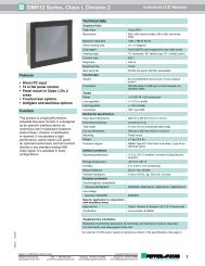
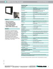
IntroductionThank you for choosing a <strong>Pepperl+Fuchs</strong> monitor. We’ve designed our products for easy installation,configuration, and use. While there is nothing difficult or “tricky” about installing the monitor, you shouldread this entire manual prior to installation. It isn’t long, and may save you some time in the end. If, afterreading this manual and visually inspecting the monitor, you are still unsure of how to properly install andoperate, please ask for assistance.This monitor is an “analog” monitor. This means it is designed to automatically work with any standardanalog video signal and standard video cable from a computer. There are no special hardware modules,PROMS, cables, or custom software drivers required.Warnings and CautionsThis product is not intended for use in critical applications where it’s failure to operate would createimmediate life threatening circumstances. Applications including but not limited to nuclear reactor control,aerospace navigation systems, and life support systems are not appropriate for this product.This product contains a high voltage inverter circuit. When powered, internal voltages present can belethal. There are no user serviceable parts inside. Please direct all service work to the manufacturer or anauthorized repair facility.This product contains sensitive electronic components and glass. Dropping or extreme shocks maydamage or break the glass. Such abuse is not covered under warranty.This product is intended to be mounted in a suitable cabinet or other enclosure. The NEMA 12, 13, 4ratings are applicable only when properly installed in a like rated enclosure.Power SupplyThis product requires a regulated external power source to provide power as follows:DM518 seriesDM519 seriesOutput line regulationOutput load regulation+12 VDC 3.8 amps continuous+12 VDC 3.2 amps continuous+/- .2% or better+/- 5% or betterUse a listed power supply, rated as above and marked Class 2, Limited Power Source, or LPS. Followlocal wiring codes and regulations that may apply. For applications requiring CE marking, a Series B orgreater product is required. Also, you must use a CE marked power supply.2
Cabinet or Panel MountingYour monitor is designed for easy panel mounting in a control or machine cabinet. Make sure the mountingsurface is flat so as not to bend or twist the bezel or compromise the usefulness of the outer gasket. Usethe 14 mounting clips provided to secure your monitor from the inside of the cabinet. Note: the LSX18 andLSX19 have the same outer dimensions and mounting instructions. Follow these 4 steps:Note:The outer dimensions of the front bezel are:DM518 series and DM519 seriesMaximum allowed wall thickness of enclosure19.0” W x 16.2” H (483 mm x 411 mm)0.25” (6.4 mm)1. Cut or punch a rectangular hole in your cabinet or panel. Clean and deburr the edges.DM518 series and DM519 seriesPanel cut out to be: 17.92” W x 15.17” H +/- .07”(455 mm x 385 mm +/- 2 mm)2. Pre-assemble themounting clips by threadingeach thumbscrew about 1/4of the way into a clip. Notethe thumb head goes on the2-prong side of the clip andthe threaded side goestowards the single prongside.3. Locate the rectangularmounting slots in the rearmetal case of yourmonitor. There are 14slots located on top,bottom, and each side.4. With the monitorplaced in the panelcutout, insert the clips,single prong side first,into the rectangularslots. Tighten thethumbscrews firmly tocompress the outergasket; when tight thefront bezel shouldalmost touch yourenclosure surface.Rear of monitorFrontbezel3
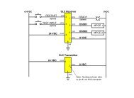
Wiring the MonitorThere are several electrical connections to be made depending on your exact monitor configuration. Allconnectors are located in the middle of the rear enclosure and designed for space saving cable routing.1. PC Video InputThis is an industry-standard, 15-pin, VGA connector. Note that this connector has 3 rows of 5pins each. You must supply a high quality cable between this connector and the video port onyour computer, maximum 100 feet (30 meters).2. NTSC Video Input (option)This is an industry-standard BNC connector. You must supply a coaxial cable between thisconnector and the live video port on your camera, video player, etc.3. Serial or USB Touch Screen Output (option, choose and use only one!)This is an industry-standard, 9-pin, female RS-232C connector or USB 2.0 connector.You must supply a cable between this connector and either a serial port or USB port onyour computer. A serial cable should use all 9 wires connected straight through (notcrossed) and will have a male end at the monitor and a female end at thecomputer. Maximum length is 50 feet (15 meters) without a repeater or modem. AUSB cable will have an ‘A’ type and ‘B’ type end, maximum length 10 feet (3meters) without a repeater or extender.3. Power Supply InputAn external 12 VDC supply is required for all system power. Youshould connect a well regulated supply wired as shown. Caution- Incorrect application of power could seriously damageyour monitor and is not covered under warranty. Werecommend you verify correct pin assignments and voltage witha meter prior to final connection. Use 20 to 14 gauge wire and 12inch pounds torque.CAUTIONRegulated 12 VDC Only+ -WARNING: EXPLOSION HAZARD - Do NOT disconnect equipment unless powerhas been switched off or the area is known to be non-hazardousNote: Connect +12 VDC to the terminal marked +Connect return to the terminal marked -4. Chassis GroundA grounding stud is located on the side. Connect a ground wire directly from this stud toearth and/or cabinet ground.Note:is your symbol for earth ground.4
Configuring your Computer’s Video Software DriversThere are no special software drivers required for your <strong>Pepperl+Fuchs</strong> monitor. Select a standard analogdriver in your computer’s software. Most reputable computer vendors supply documentation on how toconfigure their software drivers and hardware adapter. If you have trouble, your computer vendor shouldoffer technical support in this area. The following parameters are most important:Resolution 640 x 480 (VGA) or 800 x 600 (SVGA) or 1024 x 768 (XGA)or 1280 x 1024 (SXGA) {SXGA is preferred and is the native mode}Color depth up to 24 bit / 16.7 million / true color {these all mean the same thing}Vertical refresh or scan rate 60 to 75 Hz {do not use an I or interlaced driver}normally 60 Hz is recommended; with LCD technology there is no benefit to higher ratesNote that video RAM memory in your computer has a lot to do with the maximum configurable monitorparameters. Your <strong>Pepperl+Fuchs</strong> monitor is capable of displaying SXGA resolution at true color depth atup to 75 Hertz, but only if your computer’s video hardware and software will support these. You will need 8Mb of video RAM to operate this monitor to full performance. Note that video RAM is separate from anddifferent from system RAM memory.Loading Touch Screen Software (DM518 & DM519 Series)Touch screen versions of CDPI monitors incorporate either the Elo TouchSystems AccuTouch controller or3M Dynapro NFI controller. Either includes a touch screen as the front surface of the display, an embeddedcontroller, and software device drivers for you to install into your computer. Note: some computers willautomatically detect and install the device driver software for you. If so, skip to the calibration step andperform calibration.Please be sure the graphical image has been set up and is correctly positioned on the screen prior tocalibrating the touchscreen.Choose and install the correct driver for your operating system; additional instructions are located in a textfile on the floppy or CD included with your monitor.For resistive touch screens you must declare and install serial or USB interface. After configuration, youshould perform the standard calibration utility. You are presented 3 targets to press, then offset informationis stored.For capacitive touch screens you will use a serial interface. After installation, you should:• Perform the baseline calibration (important: do not touch screen during this process)• Skip the linearization process (this was done at the factory)• Perform the calibration; press the 4 targets as presented, then offset information is stored.5
Adjusting the Video ImageOften, the <strong>Pepperl+Fuchs</strong> industrial monitors just work right out of the box with no further configuration orset up. However, there are quite a few image, size, and position adjustments available should you feel theneed.This monitor uses an on screen menu system driven by the mylar keypad on the rear of the display. Basicadjustment is accomplished via a single ‘auto adjust’ command. More subtle attributes may be furtherconfigured using the menu system if desired. Generally the auto configuration is all that is needed; unlessyou specifically need to adjust another attribute, we recommend you do not use any feature otherthan the standard Auto Adjust. Follow these steps to perform an Auto Adjust.Note! For proper position and sizing, have a graphical image on the display during configuration. Donot use an all black or DOS style text mode background.ADJUSTADJUSTSELECTSELECTMENUMylar keypadPress the Menu button on the keypad. A top level menuappears on the center of the display, superimposed over theexisting computer video image.Press the Menu button again to enable the Image Adjustsubmenu.Press the Menu button once again to start the Auto Adjustfunction.The video image will freeze for up to 5 seconds sizing andpositioning itself, ultimately moving to the center and filling fullscreen. When complete, either press Menu again at the “Smile”,or do nothing and the settings will be automatically stored and themenu released.If needed, when complete, move to the Save and Exit functionby pressing the Select 5 times, and then the Menu buttononce.If you need to adjust other video modes, follow the same procedure foreach mode the computer will operate in (such as 1024 x 768).6
Diagnostic MessagesAt power up or during operation, you may see one of the following text messages displayed in a gray box.The monitor is internally generating these informational messages, not your computer.‘Video Input Lost’Video signal to monitor is not present or has been lost. Check cables and output from computer. Be surecomputer screen saver or energy saver has not shut off video output.‘Video Input Not Valid’Video resolution too high, or non standard. Verify within acceptable range.• 1280 x 1024 maximum• 75 Hz maximumTo resolve this issue you may have to restart your computer in ‘Safe Mode’ in order to get video back, andthen change to a more acceptable resolution.Other Information1. Cleaning the screenStandard resistive touch screen models have a polyester coating over the front glass surface. Use any mildglass cleaner with a soft cloth. Do not use abrasives as scratching would damage this surface.Capacitive, hardened resistive, and standard (non-touch screen) models have a hardened glass surface.Use any type of glass cleaner with a soft cloth. These surfaces are more resistant to scratching.2. Screen SaverLCD technology does not “burn in” like CRTs might when a single image is displayed for a very long periodof time. Therefore, there is no functional reason or requirement to implement a screen saver.3. Energy SaverEven when running, your flat monitor consumes very little power. In order to conserve energy, or prolongthe life of the back lamps you may implement an energy saver function in your computer. When the monitordetects the energy saver mode or loss of video signal, the back lamps power down and the screen goesdark. They will automatically turn on when normal mode is reestablished in the computer.4. Touch Screen ActivationDo use your finger, gloved finger, or other SOFT stylusDo NOT use hard metal object like screw driver, awl, key, knife.7
TroubleshootingScreen is completely blank (dark)No power to unitNo video signal, or computer screen saver is active, or computer energy conservation mode is activeIf you are sure there is power and video try cycling power to the monitorSlow scrolling bright and dim horizontal lines, image is stablePower supply is not well regulated - find a better supplyImage is stable but shadowed and/or smeared looking and/or random background “shimmer”“Noise” on the video lines. Recommend shorter cable or high quality coaxial cable. If your video cable isextremely long, try removing the shield at the monitor end only. This is the wire connecting the outer cablebraid to the metal connector shell at the monitor side.Can’t configure my computer to 24 bit color, or 1280 x 1024 resolution, or both at the same timeVideo driver hardware in your computer lacks sufficient memory. Upgrade module, or add video memory ifpossible (this is different from system RAM). Alternatively, you may reconfigure your computer softwarevideo driver for either less color depth, or less resolution, or both. See chart in “Configuring your VideoSoftware Drivers” section. We recommend maintaining 1280 x 1024 resolution and reducing color depthfirst.Image is too small, repeated on the screen vertically, and barely legibleComputer configured for too fast a refresh rate - maximum acceptable is 75 Hz. Use non-interlaced mode.Touch screen does not respond at allVerify monitor is powered prior to any startup or reboot of PC. Note NFI capacitive screens require closeproximity touch by operators finger to activate (gloves OK but pencil point, stick, screw driver, etc are not).Touch screen does not line up where I press with my fingerRun touch screen calibration utility again.If all else fails, consider a power cycle to the monitor and the computer.Contacting UsIf you need to contact <strong>Pepperl+Fuchs</strong> for any reason please have the following information available: Product part number, series, and serial number (located on rear name plate) Your name, company, and location where you are working A phone number where we can contact you if we need to research your inquiry and call back The nature and urgency of your inquiryTelephone inquiries to Twinsburg, OH USA [Eastern Time Zone] (330) 486-0002Fax inquiries can be useful for detailed correspondence (330) 425-4607Email is monitored regularly; digital photos can be usefulpa-info@us.pepperl-fuchs.com8