1-HP-004-2 - Carl Kurt Walther GmbH & Co. KG
1-HP-004-2 - Carl Kurt Walther GmbH & Co. KG
1-HP-004-2 - Carl Kurt Walther GmbH & Co. KG

You also want an ePaper? Increase the reach of your titles
YUMPU automatically turns print PDFs into web optimized ePapers that Google loves.
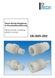
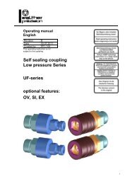
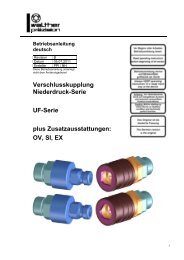
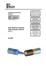
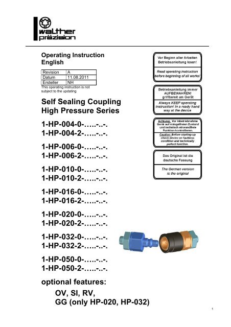
Operating InstructionEnglishRevision ADatum 11.08.2011Ersteller NHThis operating instruction is notsubject to the updatingSelf Sealing <strong>Co</strong>uplingHigh Pressure Series1-<strong>HP</strong>-<strong>004</strong>-0-…..-..-.1-<strong>HP</strong>-<strong>004</strong>-2-…..-..-.1-<strong>HP</strong>-006-0-…..-..-.1-<strong>HP</strong>-006-2-…..-..-.1-<strong>HP</strong>-010-0-…..-..-.1-<strong>HP</strong>-010-2-…..-..-.1-<strong>HP</strong>-016-0-…..-..-.1-<strong>HP</strong>-016-2-…..-..-.1-<strong>HP</strong>-020-0-…..-..-.1-<strong>HP</strong>-020-2-…..-..-.1-<strong>HP</strong>-032-0-…..-..-.1-<strong>HP</strong>-032-2-…..-..-.1-<strong>HP</strong>-050-0-…..-..-.1-<strong>HP</strong>-050-2-…..-..-.optional features:OV, SI, RV,GG (only <strong>HP</strong>-020, <strong>HP</strong>-032)1
This coupling is a quality product, in which special attention has been paidto high functionality, ease of operation, safety and reliability. As an item oftechnical equipment this coupling is intended for use in the commercial,industrial area and for operators, who have been trained by specialists in thehandling of technical systems / tools.Customer care:As part of our individual customer care we will be happy to assist you inquestions relating to use and operation and on any problems encountered.Service and maintenance:In order to maintain the high technical performance capability and reliabilityof your coupling over many years, we recommend regular inspection andmaintenance.We can thereby offer you optimum support by our Customer Servicedepartment and the conclusion of a service and maintenance contract.Please ask for a quotation.<strong>Carl</strong> <strong>Kurt</strong> <strong>Walther</strong> <strong>GmbH</strong> & <strong>Co</strong>. <strong>KG</strong>PO Box 42 04 4442781 HaanWestfalenstraße 2Tel.: +49 (0) 2129 567-0Fax: +49 (0) 2129 567 450E-Mail: info@walther-praezision.deInternet: www.walther-praezision.de<strong>Co</strong>ntact:Application technology and serviceHolger R. FiggeTelephone: (02129) 567-591Telefax: (02129) 567-590Handy: (0162) 2090100e-mail: hfigge@walther-praezision.deFurther addresses and telephone numbers of contacts can befound on the Internet on our homepage underwww.walther-praezision.de “Service / Customer service”.2
Operating InstructionEnglishType <strong>HP</strong>-seriesList of <strong>Co</strong>ntents1 List of <strong>Co</strong>ntents1 LIST OF CONTENTS ....................................................................................................................................... 32 GENERAL.......................................................................................................................................................... 43 WARRANTY...................................................................................................................................................... 54 SAFETY INSTRUCTION................................................................................................................................. 65 PRODUCT DESCRIPTION OF THE SELF SEALING COUPLING ......................................................... 75.1 USAGE ACCORDING TO SPECIFICATION......................................................................................................... 75.2 TECHNICAL DATA ........................................................................................................................................ 85.3 OPTIONAL FEATURES ................................................................................................................................... 96 INSTALLATION INSTRUCTION ................................................................................................................ 107 OPERATING INSTRUCTION....................................................................................................................... 117.1 CONNECTION PROCESS ............................................................................................................................... 117.2 DISCONNECTION PROCESS .......................................................................................................................... 117.3 SAFETY LOCKING DEVICE SI (SUPPLEMENTARY EQUIPMENT)..................................................................... 127.3.1 <strong>Co</strong>upling process................................................................................................................................... 127.3.2 Decoupling process............................................................................................................................... 128 MAINTENANCE INSTRUCTION ................................................................................................................ 138.1 MAINTENANCE AND FUNCTIONAL TEST...................................................................................................... 138.1.1 Maintenance includes following items:................................................................................................. 138.1.2 Functional test includes following items:.............................................................................................. 139 TEST ................................................................................................................................................................. 1410 LUBRICATION !......................................................................................................................................... 1511 STORAGE.................................................................................................................................................... 1612 SHUT-DOWN .............................................................................................................................................. 1713 ORDER NUMBER CODE.......................................................................................................................... 1814 INDEX .......................................................................................................................................................... 193
Operating InstructionEnglishType <strong>HP</strong>-seriesGeneral2 GeneralThis manual contains all regulations for operation, commissioning and maintenance ofthe self sealing coupling elements.All information and notes in this operating manual were collated while taking into considerationthe valid regulations, the current engineering related status of development as well as our manyyears of experience and acquired knowledge.Translations of this operating manual were also produced according to the best of knowledge.However, we cannot assume liability for any translation errors.The German version provided for this operating manual is considered the authoritative version.The actual scope of delivery can deviate from the explanations and graphic representationsdescribed herein under certain circumstances, e.g. in the case of special designs, utilization ofadditional order options or because of state-of-the-art technical alterations.If you have any questions, please contact the manufacturer.This operating manual must be read carefully before starting work on or with theequipment, in particular before commissioning!The manufacturer assumes no liability for damage or faults arising fromnon-compliance with the instructions in this operating manual.The operating manual must be kept directly with the equipment and be accessible to all personswho work on or with the equipment.It is not permitted for the operating manual to be passed to third parties and if applicable this willincur damage compensation.All other rights reserved.Before commissioning the device must be checked for being not defective and its technicallyperfect function.The German version is the original.We reserve the right to make technical alterations to the product within the context of improvingthe usage properties and further development.The operating manual remains our property.Any reproduction, use by or communication to third parties incurs a penalty and will be pursuedby court action (copyright law against unfair competition, BGB [German Civil <strong>Co</strong>de]).All rights reserved in the case of a patent award (Paragraph 7, Section. 1 of the patent law -PG) or entry as a patented design (Paragraph 5, Section 4 of the patented design law - GMG).4
Operating InstructionEnglishType <strong>HP</strong>-seriesWarranty3 WarrantyThe warranty conforms to:the regulations agreed in the purchase contract andthe “General <strong>Co</strong>nditions for Delivery and Capacity” of C.K. <strong>Walther</strong> <strong>GmbH</strong> & <strong>Co</strong>. <strong>KG</strong>of the state which was valid at the date of the purchase contract.Wearing parts are generally excluded from the warranty.Typical wearing parts of products from company C.K. <strong>Walther</strong> <strong>GmbH</strong> & <strong>Co</strong>. <strong>KG</strong>are for example:• seals• springs5
Operating InstructionEnglishType <strong>HP</strong>-series4 Safety InstructionSafety InstructionUsing these couplings does not release the customer from his obligation to comply with the pertinentwork safety regulations e.g. operational safety ordinances, etc. The duty to take due careby the operator of the couplings includes planning measures to ensure proper operation andmonitoring their implementation.Hazard notesIf the wrong product has been selected or if there is improper use or maintenance hasbeen omitted, then hazards arise and personal injuries and material damage can occurfrom:- Hazardous emission of fluid or individual particles/coupling parts- Function impairments of connected systems or tools- The metal parts of coupling and adaptor are not thermally protected. You can beburned if you touch these parts at high media temperatures . According to the ambienttemperature valve lever and ring grip can also become unbearably hot. For that reasonsuitable, sufficiently long protective gloves should be worn.The operator must in particular make sure that- The couplings are only used according to the intended purpose.- The couplings are only operated in a perfect, functioning condition.- The operating manual is always in a legible condition and is available in its entirety tooperating personnel.- The operating personnel are sufficiently acquainted with the working method and thesafety notes for the coupling.- The coupling is sent to our factory for repair work.- During operation of the coupling, no safety devices are removed and/or deactivated.- Before installing or dismantling the coupling, you have made sure that the coupling hasnot been pressurized.After completing assembly and installation work and before commissioning the coupling,observe the following points:Check once again that all screw connections are securely fitted.Before commissioning the coupling, a function test must be carried out (see maintenanceand function test).6
Operating InstructionEnglishType <strong>HP</strong>-seriese coupling5 Product description of the self sealing coupling- <strong>Co</strong>upling connection consists of:- self sealing coupling 1-<strong>HP</strong>-…-0- self sealing adaptor 1-<strong>HP</strong>-…-2- The following combinations of the coupling connections are also possible:- self sealing coupling 1-<strong>HP</strong>-…-0- thru type adaptor 1-<strong>HP</strong>-…-1- thru type coupling 1-<strong>HP</strong>-…-4- thru type adaptor 1-<strong>HP</strong>-…-1In case that both coupling halves are not connected they should be protected againstexternal dirt and/or damages if required.- For that purpose dust cap and dust plug are available.Possible combinations :self sealing couplingorthru type couplingwithdust plugself sealing adaptororthru type adaptorwithdust cap1-<strong>HP</strong>-…-01-<strong>HP</strong>-…-41-<strong>HP</strong>-…-61-<strong>HP</strong>-…-21-<strong>HP</strong>-…-11-<strong>HP</strong>-…-55.1 Usage according to specification- <strong>Co</strong>upling is only used as connection of two lines.- <strong>Co</strong>nnection and disconnection process is carried out by hand.- The self sealing coupling has a protection unintentional disconnectionin case of vibrations.- <strong>Co</strong>upling is especially suitable for the following media/applications:- air- hydraulic oil- and their subspecies(such as oxygen or oil with additives)- For all other possible applications, C.K. <strong>Walther</strong> should be consulted.7
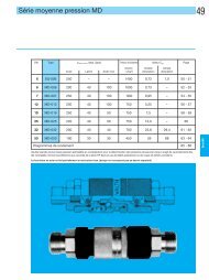
Operating InstructionEnglishType <strong>HP</strong>-seriese coupling5.2 Technical Data- Working pressures of the coupling depend on materials of individual parts.- When determining working pressure of the coupling the max. permissible working pressureof the end connection is to be taken into account if standardized threads are used.DN Type Pmax. zul.(bar)steelStainless steel1.4404 / 1.4571(stat.)Stainless steel1.4404 / 1.4571mit 1.4418 QT900Burstpressure(steel)(bar)Cv-valueboth sidesself sealingCV-valueone sidesself sealing4 <strong>HP</strong>-<strong>004</strong> 2000 500 1000 4000 0,24 0,46 <strong>HP</strong>-006 1000 320 650 2300 0,65 1,010 <strong>HP</strong>-010 600 300 470 2000 1,9 2,516 <strong>HP</strong>-016 500 250 450 1800 5,5 8,120 <strong>HP</strong>-020 400 180 350 1600 8,5 13,032 <strong>HP</strong>-032 300 180 250 1300 23,8 29,450 <strong>HP</strong>-050 200 - - 1000 65 -- The coupling is not determined for any types of use other than those listed here.- Safe operation is not guaranteed if the coupling is used contrary to its intended use.- The operator of the coupling is responsible for all personal injuries or material damagethat occur from non-intended use and disregard of the technical values; the manufacturerassumes no responsibility in these cases.8
Operating InstructionEnglishType <strong>HP</strong>-seriese coupling5.3 Optional FeaturesRV = with ring valve (z.B.: 1-<strong>HP</strong>-…-0-…..-..-.-RV1-<strong>HP</strong>-…-2-…..-..-.-RV)OV = without valve (z.B.: 1-<strong>HP</strong>-…-0-…..-..-.-OV1-<strong>HP</strong>-…-2-…..-..-.-OV)SI = with protection by safety locking device (see point 5)(z.B.: 1- <strong>HP</strong>-…-0-…..-..-.-SI)without SIwith SIGG =with ring grips (aluminium cast)only <strong>HP</strong>-020, <strong>HP</strong>-032(<strong>HP</strong>-050 standard)(z.B.: 1- <strong>HP</strong>-…-0-…..-..-.-GG)9
Operating InstructionEnglishType <strong>HP</strong>-seriesInstallation instruction6 Installation InstructionInstall the self sealing coupling into the network in due consideration of thegeneral accident prevention regulations, so that:- an error-free operation according to the operating instructions is guaranteed.Please make sure that you use only the hexagon on the connection which is providedby the customer to tighten or release the coupling / adaptor when assembling ordismantling it (see picture).hexagonal housinghexagonal connection (provided by the customer)rightwrong- the self sealing coupling is predominantly used on the network side and the self sealingcoupling is mainly used on the consumer side.- exterior damage to the unit and to all movable parts is ruled out.Before installing the through type coupling and the adaptor to the piping system, make sure thatthe piping system has been sufficiently flushed/blown or cleaned.After completing the installation work, perform a function testboth depressurised and under working pressure, as describedin the operating instructions.10
Operating InstructionEnglishType <strong>HP</strong>-seriesOperating Instruction7 Operating InstructionIn order to avoid critical injuries of the staff and damage at the self sealing coupling duringoperation, coupling may be only used for the stated applications.7.1 <strong>Co</strong>nnection processBefore every couple cycle a visual check of coupling and adaptor is to be carried out.In case of recognizable, visible damage or deformations damaged parts areto be exchanged.Hold self sealing coupling firmly in one hand; with the other hand pull back locking sleeve.This has to be done against locking spring resistance.Push coupling (free half) with withdrawn locking sleeve axially centered onto plug part ofadaptor (fixed half) until sensible resistance.Bring locking sleeve with support of locking spring into starting position.Self sealing coupling and self sealing adaptor are now mechanically locked.CAUTIONPlease take care that locking sleeve is in final position, i.e.that it is flush in front with the coupling housing as otherwise noperfect lock is guaranteed.7.2 Disconnection processWithdraw locking sleeve against locking spring and take out coupling from self sealing adaptor.Caution!In case of an available pressure in the line connected by thecoupling system a strong separation impulse - depending onthe pressure - can be effective onto the coupling system during disconnection.For that reason the movable part of the coupling (free half) is to be firmlyheld in the hand to avoid injuries.11
Operating InstructionEnglishType <strong>HP</strong>-seriesMaintenance andFunctional Instruction8 Maintenance InstructionPreventive maintenance measuresWALTHER self sealing couplings are to be operated in such a manner that external damages toelements and all moving parts are avoided.8.1 Maintenance and functional testIn order to always guarantee function of the self sealing coupling and hence safety of operator,a maintenance and functional testing must be made in appropriate periods of timedepending on operating conditions.In order to minimize operating forces and to extend service life of the self sealing couplingwe recommend to slightly grease plug surfaces (see item 10.0).8.1.1 Maintenance includes following items:- A visual inspection of self sealing coupling and self sealing adaptor regarding damageand contamination has to be made.- Dirt at the functional area (sealing area, operating elements) which is easily accessiblefrom outside should be removed by simply wiping-off.If there are damaged, torn or corroded parts, coupling must be dismounted and returnedto manufacturer for repair.If worn or embrittled seals are found or if there is extreme dirt, the customer can decidewhether he returns coupling unit to the manufacturer's factory or whether he repairs himself.8.1.2 Functional test includes following items:As described in the operating instruction, coupling is several times connected,pressurized and then disconnected.In doing so, the following has to be observed:- <strong>Co</strong>nnection and disconnection process must be absolutely smooth.- <strong>Co</strong>upling must be absolutely leak-proof in connected and disconnected state.If there are damaged, torn or corroded parts, coupling must be dismounted and returned tomanufacturer for repair.If worn or embrittled seals are found or if there is extreme dirt, the customer can decidewhether he returns the coupling unit to the manufacturer´s factory or whether he repairshimself.Please note !If the coupling is repaired by the customer themselves, a pressure and/orleak test must be performed in any case.The sequence and extent of this test is described in section “Test“.Please note !The manufacturer’s warranty shall not apply to the end product if it isrepaired by other than the manufacturer, <strong>Walther</strong>-Präzision.13
Operating InstructionEnglishType <strong>HP</strong>-seriesTest9 TestThese leak tests must be performed according to the following specifications.(Extract from the test instructions QM-PA 3.0 of the <strong>Walther</strong>-Präzision QM system)- Description:The coupling is pressure tested according to the following values.SeriesHighpressurebronzedsteelchemicallynickel-platedsteel1.44041.45711.4404 / 1.4571mit 1.4418QT900<strong>HP</strong>-<strong>004</strong> 3000 bar 3000 bar 660 bar 1300 bar<strong>HP</strong>-006 1300 bar 1300 bar 420 bar 860 bar<strong>HP</strong>-010 780 bar 780 bar 390 bar 620 bar<strong>HP</strong>-016 660 bar 660 bar 330 bar 600 bar<strong>HP</strong>-020 520 bar 520 bar 240 bar 460 bar<strong>HP</strong>-032 390 bar 390 bar 240 bar 330 bar<strong>HP</strong>-050 260 bar 260 barThe pressure details charted above are only valid for the end fittings stated in the<strong>Walther</strong> Technical Catalogue.Other end fittings (e.g. SL connections) have to be tested according tothe state of the art.If the material is steel, the test must be performed on an oil test stand.If the material is stainless steel, the test must be performed on a water test stand.In case of EPDM seals, please use the water test stand.Attention:Do not test EPDM seals with oil.- Test setup and test procedure self sealing couplingTest 1: self sealing coupling andself sealing adaptorself sealing adaptor connectedTest 2: self sealing coupling disconnectedTest 3: self sealing adaptor disconnected- Notes and remarks:The dwell time per test is 10 seconds.During the 10 seconds dwell time there must not be any visible leaks.Remove the test medium after testing, e.g. by blowing it out.- Documentation:Please document the test pressure, test medium and name/date of each test.14
Operating InstructionEnglishType <strong>HP</strong>-seriesLubrication10 Lubrication !In order to minimize operating forces and to extend service life of the coupling werecommend to slightly grease plug surfaces.Lubrication is to be carried out with greases which do not tend to become resin.Caution !The selection of the grease is to be suited to the sealing qualityand the medium (e.g.: oxygen) in view of the compatibility.15
Operating InstructionEnglishType <strong>HP</strong>-seriesStorage11 StorageThe couplings must be stored in such a way that no damages can occur at the couplings.The storage conditions of the couplings must comply with the guidelines for the seals as thesecan change in properties due to improper storage.The following items must be kept:- The couplings must be stored dry.- To safely conserve the seals and that means also the couplings they should not bestored under the effect of daylight.- For protection against oxygen the seals and also the couplings shall be stored into thepacking.16
Operating InstructionEnglishType <strong>HP</strong>-seriesShut-down12 Shut-downAt the end of the service life the coupling or its components have to be disposed non-pollutingand according to the legal regulations.For that the local public or private disposal societies should be taken.17
Operating InstructionEnglishType <strong>HP</strong>-seriesOrder Number <strong>Co</strong>de13 Order number code1. 2. 3. 4. 5. 6. 7. 8. 9.X – X X - X X X – X – X X X X X – X X - X – X X X - X XX – X X - X X X – X – X X X X X – X X X X – X X X - X X1. Subject group2. SeriesSeries description consists of either two letters or two digits.3. Nominal size / nominal widthIt is rounded up or rounded down to full units.The indication can be numerical or alphanumeric.4. Type of product and design5. Type of connection6. Material:xx-x and xxxx possible7. Material (seal version):xx-x and xxxx possible8. Y- or Z-design9. Optional features18
Operating InstructionEnglishType <strong>HP</strong>-seriesIndex14 IndexAAccording to intended purpose.......................... 6Acquired knowledge.......................................... 4Adaptorl............................................................. 6air....................................................................... 7Alterations ......................................................... 4Assembly........................................................... 6C<strong>Co</strong>mmissioning.............................................. 4, 6connection ............................................... 7, 8, 18<strong>Co</strong>nnection process ......................................... 11coupling............................................................. 4<strong>Co</strong>upling.................................................. 6, 8, 17<strong>Co</strong>uplings .......................................................... 6Customer care.................................................... 2DDamage.......................................................... 4, 6Damage compensation ...................................... 4daylight............................................................ 16Disconnection process..................................... 11Disposal societies ............................................ 17dry.................................................................... 16dust cap.............................................................. 7dust plug ............................................................ 7EEPDM seals..................................................... 14Equipment ......................................................... 4Experience......................................................... 4FFaults ................................................................. 4Fluid .................................................................. 6Function............................................................. 6Function test ...................................................... 6Functionality...................................................... 2GGeneral .............................................................. 4guarantee ......................................................... 13HHazard notes...................................................... 6Hazardous emission........................................... 6hydraulic oil....................................................... 7IImplementation ................................................. 6Improvement ..................................................... 4Index................................................................ 19Inspection.......................................................... 2Installation Instruction .................................... 10LLegible condition .............................................. 6Liability............................................................. 4List of <strong>Co</strong>ntents................................................. 3Lubrication...................................................... 15MMaintenance.............................................. 2, 4, 6Maintenance and functional test...................... 13Maintenance Instruction.................................. 13Manual .............................................................. 4Media temperatures........................................... 6OOperating Instruction .................................. 1, 11Operation........................................................... 2Operational safety ordinances........................... 6operator ....................................................... 6, 13Operator ............................................................ 8Operators........................................................... 2original .............................................................. 4Ppacking............................................................ 16particular ........................................................... 6Perfect, functioning condition........................... 6Performance capability...................................... 2Pressurized ........................................................ 6Product description ........................................... 7Property............................................................. 4Protective gloves ............................................... 6Qquality.............................................................. 15questions............................................................ 4RRegulations........................................................ 4Reliability.......................................................... 2remarks............................................................ 14Repair work....................................................... 619
Operating InstructionEnglishType <strong>HP</strong>-seriesIndexSSafety................................................................. 2Safety devices.................................................... 6Safety Instruction .............................................. 6Scope of delivery............................................... 4Screw connections............................................. 6self sealing adaptor................................ 7, 11, 13self sealing coupling.............................. 7, 11, 13Self sealing coupling ....................................... 11Self Sealing <strong>Co</strong>upling........................................ 1service........................................................ 13, 15Service............................................................... 2Shut-down ....................................................... 17Special designs .................................................. 4Specialists.......................................................... 2specification ...................................................... 8Status of development ....................................... 4Storage............................................................. 16subspecies.......................................................... 7Systems.......................................................... 2, 6TTechnical equipment ......................................... 2Test.................................................................. 14Thermally.......................................................... 6thru type adaptor ............................................... 7thru type coupling ............................................. 7Tools ............................................................. 2, 6Translation errors .............................................. 4Types of use ...................................................... 8UUse .................................................................... 2VVersion.............................................................. 4WWork safety regulations .................................... 6Working method ............................................... 6Wrong product selection ................................... 620