Ultrafast Temporal Magnifier - Thorlabs
Ultrafast Temporal Magnifier - Thorlabs
Ultrafast Temporal Magnifier - Thorlabs

You also want an ePaper? Increase the reach of your titles
YUMPU automatically turns print PDFs into web optimized ePapers that Google loves.
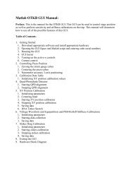
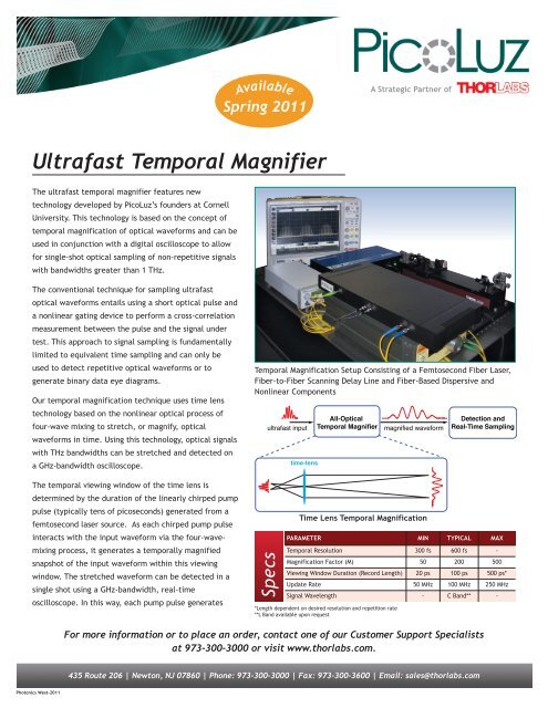
AvailableSpring 2011A Strategic Partner of<strong>Ultrafast</strong> <strong>Temporal</strong> <strong>Magnifier</strong>The ultrafast temporal magnifier features newtechnology developed by PicoLuz’s founders at CornellUniversity. This technology is based on the concept oftemporal magnification of optical waveforms and can beused in conjunction with a digital oscilloscope to allowfor single-shot optical sampling of non-repetitive signalswith bandwidths greater than 1 THz.The conventional technique for sampling ultrafastoptical waveforms entails using a short optical pulse anda nonlinear gating device to perform a cross-correlationmeasurement between the pulse and the signal undertest. This approach to signal sampling is fundamentallylimited to equivalent time sampling and can only beused to detect repetitive optical waveforms or togenerate binary data eye diagrams.Our temporal magnification technique uses time lenstechnology based on the nonlinear optical process offour-wave mixing to stretch, or magnify, opticalwaveforms in time. Using this technology, optical signalswith THz bandwidths can be stretched and detected ona GHz-bandwidth oscilloscope.<strong>Temporal</strong> Magnification Setup Consisting of a Femtosecond Fiber Laser,Fiber-to-Fiber Scanning Delay Line and Fiber-Based Dispersive andNonlinear Componentsultrafast inputtime-lensAll-Optical<strong>Temporal</strong> <strong>Magnifier</strong>magnified waveformDetection andReal-Time SamplingThe temporal viewing window of the time lens isdetermined by the duration of the linearly chirped pumppulse (typically tens of picoseconds) generated from afemtosecond laser source. As each chirped pump pulseinteracts with the input waveform via the four-wavemixingprocess, it generates a temporally magnifiedsnapshot of the input waveform within this viewingwindow. The stretched waveform can be detected in asingle shot using a GHz-bandwidth, real-timeoscilloscope. In this way, each pump pulse generatesSpecsTime Lens <strong>Temporal</strong> MagnificationPARAMETER MIN TYPICAL MAX<strong>Temporal</strong> Resolution 300 fs 600 fs -Magnification Factor (M) 50 200 500Viewing Window Duration (Record Length) 20 ps 100 ps 500 ps*Update Rate 50 MHz 100 MHz 250 MHzSignal Wavelength - C Band** -*Length dependent on desired resolution and repetition rate**L Band available upon requestFor more information or to place an order, contact one of our Customer Support Specialistsat 973-300-3000 or visit www.thorlabs.com.435 Route 206 | Newton, NJ 07860 | Phone: 973-300-3000 | Fax: 973-300-3600 | Email: sales@thorlabs.comPhotonics West-2011
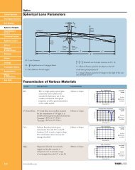
hundreds of sample points, and the sampled waveform is updatedevery time a new pump pulse overlaps with the input signal.Analogous to a reading magnifying glass, the time lens can sample a continuous waveform by scanningthe pump pulse over the input via an adjustable delay line. Our time lens system features a fiber-to-fiber adjustabledelay line that uses a <strong>Thorlabs</strong>, long travel, motorized stage. This long travel stage can sweep the time lens viewing window relativeto the input to cover very long or continuous waveforms. The delay line can also be used to temporally align a short input waveformwithin the time lens viewing window.When used in conjunction with a real-time oscilloscope, a time lens can be used for detecting non-repetitive, ultrafast opticalwaveforms. In this case, the sampling rate of the system will be the magnification factor (M) multiplied by the real-time samplingrate of the oscilloscope. For example, when a temporal magnification system with M = 200 is used with a 20 GS/s oscilloscope, thewaveform is sampled at a 4 TS/s sampling rate. This system can also be paired with a conventional digital communication analyzerto generate digital data eye diagram measurements at rates greater than 1 Tb/s.pump source(fiber laser)ultrafast signalunder testpump dispersiveelementchirped pump pulseinput dispersiveelementScanningDelayLinenonlinearwaveguideWDMcombinerdetector & oscilloscope(magnified output)Schematic Diagram Showing the Concept of <strong>Temporal</strong> Magnification Using the Four-Wave Mixing (FWM) Time Lensfilteroutput dispersiveelementInput Cross-Correlation(Multi-Shot, Averaged)Output on 5 GHz Oscilloscope(M = 65, Single-Shot)IntensityTime (5 ps/div)Time (500 ps/div)IntensityIntensityIntensityInput Cross-CorrelationMagnified Output(M = 520)Time (5 ps/div)Time (2.5 ns/div)Sample Input Signals Shown Before and After <strong>Temporal</strong> MagnificationR. Salem, M. A. Foster, A. C. Turner-Foster, D. F. Geraghty, M. Lipson, and A. L. Gaeta, “High-speed optical sampling using a siliconchiptemporal magnifier,” Opt. Express 17, 4324-4329 (2009).For more information or to place an order, contact one of our Customer Support Specialistsat 973-300-3000 or visit www.thorlabs.com.435 Route 206 | Newton, NJ 07860 | Phone: 973-300-3000 | Fax: 973-300-3600 | Email: sales@thorlabs.com