Installation guide: Guided Wave Radar GWR2 - WEKA AG
Installation guide: Guided Wave Radar GWR2 - WEKA AG
Installation guide: Guided Wave Radar GWR2 - WEKA AG

You also want an ePaper? Increase the reach of your titles
YUMPU automatically turns print PDFs into web optimized ePapers that Google loves.
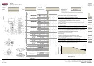
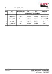
Data sheet: <strong>GWR2</strong>Control elements-4-Figure 5: StickerSimply press an orange lever straight down with a small flat tipscrewdriver, insert a stripped wire end into the terminal hole, and releasethe orange lever; the wire is now connected.The upper sticker inside the housing illustrates the inputs and outputs ifthe sensor. Connect all wires accordingly.Pull the cable back, but make sure its mantle does not retract into thecable gland.Tighten the cable gland to ensure proper sealing function.Switch on the power supply for the sensor.The sensor LED should start blinking green within 6 seconds afterconnecting the power (during this start-up time the LED is off). Theblinking green LED indicates that the sensor is in measuring mode andworking correctly.Do not tighten the housing cover yet. Some basic configuration is still tobe done…<strong>GWR2</strong>’s electronic is galvanically completely insulated from itsinputs/outputs and the tank potential; thus avoiding any problems fromelectrochemical corrosion protection of the tank. For further details aboutthis feature, please refer to the operations manual.Figure 6: Control elementsControl elementsBasic configuration of <strong>GWR2</strong> can be done directly on the device via threecontrol elements: a DIP switch, a single push button and a LED for visualfeedback. All settings required to get <strong>GWR2</strong> fully operational can beperformed directly on the device; or <strong>GWR2</strong> can be ordered completelypre-configured.All three control elements are enclosed in the black plastic cartridgeinside the housing.The DIP switch has 8 small white levers. Small numbers from 1 to 8 areprinted underneath the levers: they indicate the DIP switch positions andcorrespond to the ones in figure 7.The upper position of a lever is off/0 and the lower position is on/1. Onthe left side of the DIP switch is also a small indication of the on/1 state.The off/0 and on/1 states of the DIP switch correspond to the 0/1indications in figure 7.The upper sticker on the black plastic cartridge shows three coloursegments close to the DIP switch: red, gray, and blue; they correspond tothe coloured rows in figure 7.• red: indicates DIP switch position 8 which switches between measuring and configuration mode. Only when DIP switch position 8 ison/1, <strong>GWR2</strong> can be configured; configuration mode is indicated by the LED blinking alternately green and red.When DIP switch position 8 is off/0, <strong>GWR2</strong> is in measuring mode; indicated by the LED blinking green.It is only possible to enter the configuration mode when DIP switch positions 1 to 7 are off/0 before setting DIP switch position 8 toon/1; otherwise the LED is blinking red to indicate an error• blue: indicates the DIP positions through which groups of functions are selected, e.g. all functions related to the analog current outputor the switching output• gray: indicates the DIP positions through which individual functions/configuration settings are selectedAfter setting all DIP switch positions to represent the 0/1 sequence of the desired function (as described in figure 2), the push button hasto be pressed to execute the desired function. Execution of the function is indicated by the LED remaining green until the function hasbeen properly executed, in which case the LED returns to blinking alternately green and red.IG_GWR_E_2009_11_22<strong>WEKA</strong> <strong>AG</strong> - Schürlistrasse 8 - CH-8344 BäretswilTechnical modifications reserved! Tel. ++41 (0)43 833 43 43 - Fax ++41 (0)43 833 43 2923.11.2009 Ot info@weka-ag.ch - www.weka-ag.ch