Installation guide: Guided Wave Radar GWR2 - WEKA AG
Installation guide: Guided Wave Radar GWR2 - WEKA AG
Installation guide: Guided Wave Radar GWR2 - WEKA AG

You also want an ePaper? Increase the reach of your titles
YUMPU automatically turns print PDFs into web optimized ePapers that Google loves.
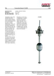
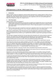
<strong>GWR2</strong><strong>Installation</strong> <strong>guide</strong>: <strong>Guided</strong> <strong>Wave</strong> <strong>Radar</strong>-1-4-wire TDR-Sensor with single rod or coaxial probe for continuous level measurement and point level detection in liquids,with analog and switching output.DOCUMENT DESCRIPTIONThis quick installation <strong>guide</strong> gives instructions for mounting, wiring, and basic configuration of <strong>GWR2</strong>.This will be sufficient to achieve a fully functional sensor in most applications.For further details and advanced configuration of <strong>GWR2</strong>, please refer to the operations manual.INSTALLATION PROCEDUREFigure 1: MountingReview thisinstallation <strong>guide</strong>MountingWiringConfigurationReliable functionMounting<strong>GWR2</strong> is mounted vertically to the tank via its connection thread, which is screwed directly into a standard threaded tank connection, i.e.weld-in socket, or it can be screwed into a flange, which is then connected to a tank nozzle.<strong>GWR2</strong> should not be welded directly into the tank. Neither should flanges be welded onto <strong>GWR2</strong>. Welding on the metal parts of <strong>GWR2</strong>will cause serious damage to the sensor.Do not lift or handle <strong>GWR2</strong> by its probe; this can cause excessive stress on the probe connection. <strong>GWR2</strong> should be handled by thehexagon or the lower section of the housing.Do not screw in <strong>GWR2</strong> by its housing; it should be tightened only via its hexagon (wrench size 32mm for connection thread G3/4"A).Tighten the coaxial probe only at its lower hexagon; the upper hexagon of the coaxial probe is not needed for mounting.The customer has to ensure proper sealing of the sensor connection; based on his process conditions like temperature, pressure andresistance against his process liquids and atmosphere.G thread connections require a suitable gasket for pressure-tight joints.The G3/4"A connection thread of <strong>GWR2</strong> is supplied with a gasket, thickness ~2mm. The suggested tightening torque for this thread size,this type of gasket and a process pressure of max. 40bar is 25Nm (maximum permissible torque: 45 Nm).For NPT thread connections, pressure-tight joints require a sealant directly on the threads.IG_GWR_E_2009_11_22<strong>WEKA</strong> <strong>AG</strong> - Schürlistrasse 8 - CH-8344 BäretswilTechnical modifications reserved! Tel. ++41 (0)43 833 43 43 - Fax ++41 (0)43 833 43 2923.11.2009 Ot info@weka-ag.ch - www.weka-ag.ch
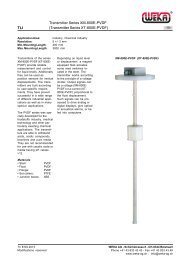
Data sheet: <strong>GWR2</strong>Mounting considerations-2-Figure 2: Mounting considerationSINGLE ROD PROBECOAXIAL PROBEnozzle diameternozzle heightclearance to tank wall or other internal objectsclearance between probe end and tank bottomdiameter of bypass chamber / stilling well- 1) >50mm- 100mm- >2mm- 2) >25mm- = no restrictions1) minimum diameter to fit in the coaxial probe (ø17,2mm)2) minimum diameter to fit in the coaxial probe (ø17,2mm)and enough room around the probe for the liquid to flowin and out of the bypass chamber / stilling wellMounting considerationsThe probes should be installed so that they are not directly impacted by liquids flowing out of the filling inlet.They should neither touch nor sway towards other objects inside the tank or the tank/nozzle walls; e.g. by agitator swirls. In applicationswith very strong fluid movements, which can also cause excessive lateral force on the probe, it is recommended to fix the probe. Theanchoring fixtures are customer supplied.For further details about fixing the single rod probe, please refer to the operations manual.The coaxial probe can be fixed to the tank wall by lateral brackets attached to the tank wall. Alternatively, a piece of tube attached to thetank bottom can serve as a socket for holding the end of the coaxial probe in place; in this case proper drainage of the socket has to beensured. Any probe fixtures should only <strong>guide</strong> the probe and not tightly fixed it; to enable movement due to thermal expansion.The single rod is suitable for a very wide range of applications and liquids, but the signal has a wider detection radius around the rod.Thus, it is more responsive for measurement signal disturbances which can be easily overcome by observing a few mountingconsiderations (see figure 1) and making simple configuration adjustments to the sensor; in most cases it is enough to activate andutilize the powerful disturbance signal suppression features of <strong>GWR2</strong>. However, those work most efficiently on stationary interferencetargets like tall and narrow nozzles or close-by objects. In case that non-stationary interference targets close to the single rod probe, likeslowly rotating agitator blades, cause problems with the measurement, it is recommended to use the coaxial probe.In any case, the single rod probe should never get in direct contact with the tank/nozzle wall or other objects in the tank.The coaxial probe does not have restrictions regarding mounting position, tank connection, and proximity to the tank wall or other objectsinside the tank. The coaxial probe is recommended for installing <strong>GWR2</strong> into a non-metallic tank or open pit. If that is not possible, asingle rod probe can be used when <strong>GWR2</strong> is mounted into at least a DN50 metal flange or screwed into a metal sheet with at leastØ150mm.<strong>GWR2</strong> is very well suited for external mounting into a bypass chamber. Thus, <strong>GWR2</strong> is also the ideal replacement for chamber-mounteddisplacers: simply remove the displacer, keep its existing chamber and fit a <strong>GWR2</strong> into it. The powerful disturbance signal suppressionfeatures of <strong>GWR2</strong> ensures easy retrofitting and reliable measurement in almost any existing displacer chamber.IG_GWR_E_2009_11_22<strong>WEKA</strong> <strong>AG</strong> - Schürlistrasse 8 - CH-8344 BäretswilTechnical modifications reserved! Tel. ++41 (0)43 833 43 43 - Fax ++41 (0)43 833 43 2923.11.2009 Ot info@weka-ag.ch - www.weka-ag.ch
Data sheet: <strong>GWR2</strong>Cable entries and wiring-3-Figure 3: Cable entriesCABLE ENTRIES AND CABLE GLANDSThe housing has two cable entries and can be ordered with assembledstandard screw plugs and cable glands. Nevertheless, the customer hasto confirm the suitability of those cable glands for his specific applicationrequirements and cabling; and replace them when necessary.Both cable entries can be fitted with cable glands. If only one cable glandis fitted, it is recommended to use cable entry D2 (see Fig. 3). Thencable entry D3 has to be closed with a suitable screw plug.IP68-rated screw plugs and cable glands have to be properly sealed andhave to be properly tightened around cable of suitable type and diameterto ensure the IP68 rating of the housing.Cable entries with metric threads can be sealed by mounting the suitablescrew plug or cable gland with matching rubber washers underneath.Cable entries with NPT threads require a sealant directly on the thread ofthe screw plug or cable gland.For M20x1,5 cable entries, <strong>GWR2</strong> comes assembled with:• 1 x cable gland M20x1,5, IP68, nylon PA66, for non-armoured cableØ5…9mm, with EPDM washer, max. tightening torque 6Nm on allhexagons, wrench size 24mm. For protection during shipment it is closedwith an EPDM sealing plug which has to be removed for cabling• 1 x screw plug, IP68, M20x1,5, nylon PA66, with EPDM washerFor ½” NPT cable entries, <strong>GWR2</strong> comes assembled with:• 2 x screw plug, 1/2" NPT, PE-LD. They are not IP68 and are only forhousing protection during shipment. They have to be replaced by thecustomerWhen wiring with shielded or armoured cable, suitable cable glands haveto be used. The contact between the metal housing and the shielding ofthe cable is made by using a suitable EMC-type cable gland. Ground theshielding of the cable only on the sensor side; not on the supply side.Figure 4: Wiring diagramWIRINGVerify that the power supply for the sensor is switched off.Establish an equipotential connection (potential equalization) betweenthe external earth terminal of <strong>GWR2</strong> and the closest ground potentialterminal of the tank.Open the housing cover by turning it counterclockwise. It may benecessary to loosen the cover locking screw with an allen key size1,5mm. The cover has a safety chain to prevent it from falling to theground after being unscrewed.The lower sticker on the black plastic cartridge inside the housing givesinstructions for the standard M20x1,5 cable gland. When other cableglands are being used, their details have to be observed instead.Loosen the cable gland and pull the cable through the cable gland intothe housing. Pull it far enough to have a convenient length for strippingand handling the cable.Install cable with a drip loop outside the housing where the bottom of theloop must be lower than the cable entry of the housing.Dismantle the cable carefully and strip the wires as indicated on thesticker.The stripped wire ends are connected to the sensor electronic via thegreen screwless, cage clamp terminal block. It can accommodatestranded and solid wires 0,5…2mm² / AWG 22...14. The usage of cableend sleeves with insulation collar is not recommended.IG_GWR_E_2009_11_22<strong>WEKA</strong> <strong>AG</strong> - Schürlistrasse 8 - CH-8344 BäretswilTechnical modifications reserved! Tel. ++41 (0)43 833 43 43 - Fax ++41 (0)43 833 43 2923.11.2009 Ot info@weka-ag.ch - www.weka-ag.ch
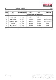
Data sheet: <strong>GWR2</strong>Control elements-4-Figure 5: StickerSimply press an orange lever straight down with a small flat tipscrewdriver, insert a stripped wire end into the terminal hole, and releasethe orange lever; the wire is now connected.The upper sticker inside the housing illustrates the inputs and outputs ifthe sensor. Connect all wires accordingly.Pull the cable back, but make sure its mantle does not retract into thecable gland.Tighten the cable gland to ensure proper sealing function.Switch on the power supply for the sensor.The sensor LED should start blinking green within 6 seconds afterconnecting the power (during this start-up time the LED is off). Theblinking green LED indicates that the sensor is in measuring mode andworking correctly.Do not tighten the housing cover yet. Some basic configuration is still tobe done…<strong>GWR2</strong>’s electronic is galvanically completely insulated from itsinputs/outputs and the tank potential; thus avoiding any problems fromelectrochemical corrosion protection of the tank. For further details aboutthis feature, please refer to the operations manual.Figure 6: Control elementsControl elementsBasic configuration of <strong>GWR2</strong> can be done directly on the device via threecontrol elements: a DIP switch, a single push button and a LED for visualfeedback. All settings required to get <strong>GWR2</strong> fully operational can beperformed directly on the device; or <strong>GWR2</strong> can be ordered completelypre-configured.All three control elements are enclosed in the black plastic cartridgeinside the housing.The DIP switch has 8 small white levers. Small numbers from 1 to 8 areprinted underneath the levers: they indicate the DIP switch positions andcorrespond to the ones in figure 7.The upper position of a lever is off/0 and the lower position is on/1. Onthe left side of the DIP switch is also a small indication of the on/1 state.The off/0 and on/1 states of the DIP switch correspond to the 0/1indications in figure 7.The upper sticker on the black plastic cartridge shows three coloursegments close to the DIP switch: red, gray, and blue; they correspond tothe coloured rows in figure 7.• red: indicates DIP switch position 8 which switches between measuring and configuration mode. Only when DIP switch position 8 ison/1, <strong>GWR2</strong> can be configured; configuration mode is indicated by the LED blinking alternately green and red.When DIP switch position 8 is off/0, <strong>GWR2</strong> is in measuring mode; indicated by the LED blinking green.It is only possible to enter the configuration mode when DIP switch positions 1 to 7 are off/0 before setting DIP switch position 8 toon/1; otherwise the LED is blinking red to indicate an error• blue: indicates the DIP positions through which groups of functions are selected, e.g. all functions related to the analog current outputor the switching output• gray: indicates the DIP positions through which individual functions/configuration settings are selectedAfter setting all DIP switch positions to represent the 0/1 sequence of the desired function (as described in figure 2), the push button hasto be pressed to execute the desired function. Execution of the function is indicated by the LED remaining green until the function hasbeen properly executed, in which case the LED returns to blinking alternately green and red.IG_GWR_E_2009_11_22<strong>WEKA</strong> <strong>AG</strong> - Schürlistrasse 8 - CH-8344 BäretswilTechnical modifications reserved! Tel. ++41 (0)43 833 43 43 - Fax ++41 (0)43 833 43 2923.11.2009 Ot info@weka-ag.ch - www.weka-ag.ch
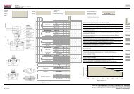
Data sheet: <strong>GWR2</strong>Configuration coaxial probe-6-Figure 12: Lower range value [4mA] = span 0%CONFIGURATION COAXIAL PROBEDIP SWITCH SETTINGS DESCRIPTIONThe coaxial probe has a very robust and reliable measurement0 0 0 1 0 0 1 1 Lower range value[4mA]; span 0%performance in almost any application without furtherconfiguration. For basic configuration only the range values forthe analog current output have to be set.For further details and advanced configuration of KFA2, pleaserefer to the operations manual.Figure 13: Upper range value [20mA] = span 100%DIP SWITCH SETTINGS DESCRIPTION1. LOWER RANGE VALUE [4mA]; SPAN 0%0 0 1 0 0 0 1 1 Upper range value [20mA]; span 100% • set the DIP switch positions to the 0/1 sequence in figure12 on the left;start from position 8 and move towards position 1!Figure 14: Measuring mode• lower the liquid inside the tank down to the level where youDIP SWITCH SETTINGS DESCRIPTIONwant to position the lower range value [4mA]; span 0%.0 0 0 0 0 0 0 0 Measuring modeIt is recommended that the lower range value stays withinthe measuring range [M]• press the push button• LED will remain green briefly while the lower range valuesetting is being executed• once it has been executed successfully, the LED will returnto blinking alternately green and red2. UPPER RANGE VALUE [20mA]; SPAN 100%• raise the liquid inside the tank up to the level where youwant to position the upper range value [20mA]; span 100%.It is recommended that the upper range value stays withinthe measuring range [M]• change DIP switch position 3 to on/1, figure 13• press the push button• LED will remain green briefly while the upper range valuesetting is being executed• once it has been executed successfully, the LED will returnto blinking alternately green and red• set all the DIP switch positions to 0 as indicated in figure14 on the left;start from position 1 and move towards position 8!• the LED will change to blinking greenTighten the housing cover properly by turning it clockwise;make sure the cover safety chain does not tangle up. Ifdesired, tighten the cover locking screw with an allen key size1,5mm.IG_GWR_E_2009_11_22<strong>WEKA</strong> <strong>AG</strong> - Schürlistrasse 8 - CH-8344 BäretswilTechnical modifications reserved! Tel. ++41 (0)43 833 43 43 - Fax ++41 (0)43 833 43 2923.11.2009 Ot info@weka-ag.ch - www.weka-ag.ch
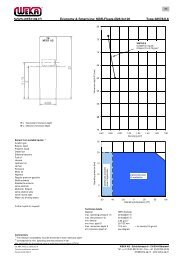
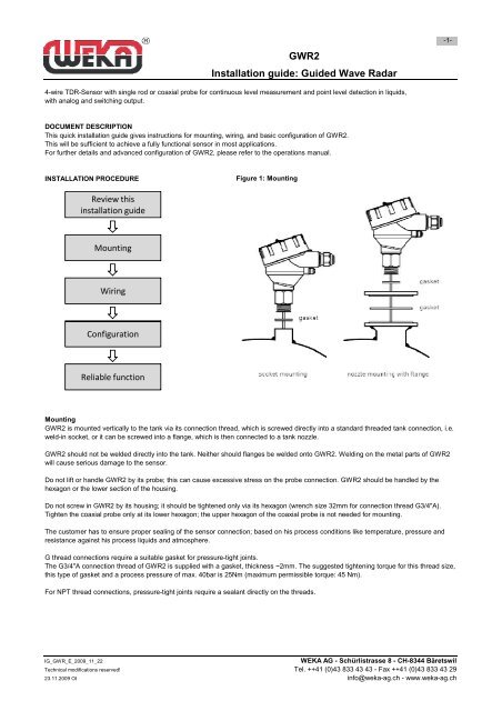
Data sheet: <strong>GWR2</strong>Probe length and measuring range-7-Figure 4: Probe length and measuring rangesealing surfaceC220mASswitch point NC/NOC1LM0…100%4mAPROBE LENGTH AND MEASURING RANGEThe reference point for definition of the probe length [L] is always the sealing surface of the connection thread.The probe length [L] is an important mechanical dimension which is needed to make sure the probe physically fits into the tank at theanticipated mounting location; it is not equal to the actual measuring range [M] of the sensor!TDR level sensors have small inactive areas at top [I1] and bottom [I2] of the probe. Those are due to the presence of unavoidable signaldisturbances at both ends of the probe. In these inactive areas the measurements are non-linear or have reduced accuracy. Therefore, itis not recommended to actually measure level within those inactive areas. Their length depends on the probe type and the reflectivity (i.e.dielectric constant) of the liquid to be measured.The measuring range [M] of <strong>GWR2</strong> extends between the top and bottom inactive areas of the probe; this is the area in which <strong>GWR2</strong> willhave the specified measurement performance. It is recommended that the maximum and minimum liquid levels to be measured in thetank are actually within the measuring range [M] of the sensor.The span between the lower range value [4mA] and the upper range value [20mA] of the analog current output is equal to 0...100% ofyour continuous level measurement reading.It is recommended that the span between those two range values stays within the measuring range [M].DISTURBANCE SIGNAL SCANThe disturbance signal scan is a powerful disturbance signal suppression feature of <strong>GWR2</strong>. The sensor scans its entire probe length forany disturbance signals in the application that could potentially be misinterpreted as level readings, memorizes and suppresses themduring operation; that way <strong>GWR2</strong> only recognizes the actual level signals caused by the liquid to be measured.The disturbance signal scan is intended for the single rod probe, since its signal has a wider detection radius around the rod, making itmore responsive for measurement signal disturbances. The disturbance signal scan works most efficiently on stationary interferencetargets like tall and narrow nozzles or close-by objects. Thus, <strong>GWR2</strong> has to be mounted in its final position and the tank has to becompletely empty in order to perform a disturbance signal scan; that will ensure a reliable identification of the actual disturbance signalsonly.In case that non-stationary interference targets close to the single rod probe, like slowly rotating agitator blades or streams of liquid beingfilled into the tank, cause problems with the measurement, it is recommended to use the coaxial probe.Performing a disturbance signal scan is the prerequisite for utilizing this feature of <strong>GWR2</strong>.IG_GWR_E_2009_11_22<strong>WEKA</strong> <strong>AG</strong> - Schürlistrasse 8 - CH-8344 BäretswilTechnical modifications reserved! Tel. ++41 (0)43 833 43 43 - Fax ++41 (0)43 833 43 2923.11.2009 Ot info@weka-ag.ch - www.weka-ag.ch
Data sheet: <strong>GWR2</strong>Electrical and measurement specifications-8-ELECTRICAL SPECIFICATIONSOutput functions4-wire systemcontinuous level measurement through analog outputand point level detection through switching outputactive current output 4…20mAThe span between the lower range value [4mA] and the upper range value [20mA]Analog outputis equal to 0...100% of the continuous level measurement reading.It isrecommended that the span between those two range values stayswithin the measuring range [M].Load for 4…20mA
Data sheet: <strong>GWR2</strong>Application and mechanical specification-9-APPLICATION SPECIFICATIONS continuous level measurement and point level detection in liquidsDielectric constant [εr] single rod probe: >1,8 coaxial probe:>1,4Conductivityno restrictionsDensityno restrictionsDynamic viscosity rod probe:
Data sheet: <strong>GWR2</strong>Dimensions-10-Single rod probeDimensions in mmCoaxial probeDimensions in mmIG_GWR_E_2009_11_22<strong>WEKA</strong> <strong>AG</strong> - Schürlistrasse 8 - CH-8344 BäretswilTechnical modifications reserved! Tel. ++41 (0)43 833 43 43 - Fax ++41 (0)43 833 43 2923.11.2009 Ot info@weka-ag.ch - www.weka-ag.ch
Data sheet: <strong>GWR2</strong>Order formCustomer:Reference number:Project:Order number:Liquid:Dielectric constant εr: single rod >1.8 / coaxial probe >1.4Viscosity: cSt single rod