Lubrication Manual for THK LM Guides - Hennlich
Lubrication Manual for THK LM Guides - Hennlich
Lubrication Manual for THK LM Guides - Hennlich

You also want an ePaper? Increase the reach of your titles
YUMPU automatically turns print PDFs into web optimized ePapers that Google loves.
Engineering and Development Department, <strong>THK</strong> European Headquarters<strong>Lubrication</strong> <strong>Manual</strong><strong>for</strong> <strong>THK</strong><strong>LM</strong> <strong>Guides</strong>© <strong>THK</strong> GmbH Booklet-EHQ-002-01
Table of contents1. GENERAL INFORMATION................................................................................................ 32. LUBRICANTS...................................................................................................................... 42.1 GLOBAL STANDARD .......................................................................................................... 42.2 <strong>THK</strong> LUBRICANTS............................................................................................................. 42.3 CODING OF THE MOUNTING ORIENTATION (ONLY FOR OIL LUBRICATION) ........................... 53. <strong>THK</strong> GREASE ADAPTER .................................................................................................. 63.1 <strong>THK</strong> STANDARD GREASE NIPPLE ...................................................................................... 63.1.1 Drive-in grease nipple............................................................................................. 63.1.2 Screwed-in grease nipple ....................................................................................... 63.2 <strong>THK</strong> PIPE FITTINGS (CENTRAL LUBRICATION SYSTEM) ...................................................... 73.3 <strong>THK</strong> GREASE PUMP NOZZLES........................................................................................... 84. LUBRICATION PROCESS AND HANDLING.................................................................. 94.1 GENERAL INFORMATION.................................................................................................... 94.2 LUBRICATION METHODS .................................................................................................... 94.2.1 Grease gun ............................................................................................................ 104.2.2 Relubrication.......................................................................................................... 104.2.3 <strong>Lubrication</strong> cycle.................................................................................................... 115. TABLES OF LUBRICATION QUANTITY OF DIFFERENT <strong>THK</strong> <strong>LM</strong> GUIDES .......... 115.1 INITIAL LUBRICATION QUANTITY: <strong>LM</strong> GUIDE WITH BALL/ROLLER CAGED TECHNOLOGY ..... 115.2 INITIAL LUBRICATION QUANTITY: <strong>LM</strong> GUIDES CONVENTIONAL (WITHOUT CAGED BALLTECHNOLOGY) ...................................................................................................................... 135.3 INITIAL LUBRICATION QUANTITY: BALL SPLINES ............................................................... 155.4 OIL LUBRICATION, OIL VOLUME ....................................................................................... 152© <strong>THK</strong> GmbH
1. General In<strong>for</strong>mationThe main purposes of lubricating stuff are to reduce friction of a system and to protectthe system against corrosion. There<strong>for</strong>e, a proper and adequate lubrication is essential<strong>for</strong> a trouble-free operation of the <strong>LM</strong> <strong>Guides</strong>. The lubricant and the method oflubrication should be selected according to the <strong>LM</strong> Guide and the application.Under normal operating conditions, the general lubrication interval is every 100 km ofoperation or every six months. This value can vary (increase or decrease) due tospecial environmental conditions or / and application requirements and as well dependson the kind of lubricant used.Such influences can <strong>for</strong> example be: high and low temperatures influence of condensation and splash water operation with radiation influence operation at high vibrations operation in vacuum or / and clean room influence of special material (e.g. steam, fume, acid etc.) high acceleration or / and velocity sustained short stroke (< two block length)Another influencing variable is dust or dirt. These can reduce the operation lifetimeconsiderably. In this case it is necessary to protect the <strong>LM</strong> <strong>Guides</strong> with <strong>THK</strong> specialsealing options at the carriage or <strong>for</strong> example with bellows or a cover.In case of order please in<strong>for</strong>m <strong>THK</strong> whether the <strong>LM</strong> <strong>Guides</strong> will be lubricated withgrease or oil. The <strong>LM</strong> blocks are filled with standard grease and protected with anticorrosionoil. Furthermore, in case of oil lubrication it is necessary to use special paperseals.The use of special additives or / and high-grade synthetic lubricants can considerablyincrease the operation lifetime. Nevertheless, it is not possible to give a meaningfulstatement about the increase of the operation lifetime because many varyingenvironmental influences are combined with customer specific applications. Thus, maincharacteristic values can only be determined by own testing under real operatingconditions/ influences.If you have any questions about this topic do not hesitate to contact the TechnicalDepartment of <strong>THK</strong>.© <strong>THK</strong> GmbH 3
2. Lubricants2.1 Global StandardFor working under normal operating conditions / influences we recommend thelubricants with the following minimum standard and minimum specification:Table 2.1 Lubricant standardLubricant DIN indication DIN number NoticeGrease KP 2 – K 51502 or 51825 Lithium soapAttention!Oil CLP32 – 100 51517 Part 3 ISO VG 32-68Lubricants with solid particle additives like MoS 2 , graphite, PTFE etc. are generally notappropriate <strong>for</strong> <strong>THK</strong> <strong>LM</strong> systems. If such greases have to be used please contact <strong>THK</strong>.2.2 <strong>THK</strong> LubricantsTable 2.2a <strong>THK</strong> Greases<strong>THK</strong>greasetypesConsistencyenhancer(Soap)Base oilBase oilviscosityat 40°CCST[mm²/S]ConsistencyclassDIN 51 818WalkingpenetrationDIN ISO2137Servicetemperaturerange (°C)ServiceenvironmentLubricant characteristicsAFAAFB -LFAFCAFE -CAUreaSyntheticoil25 1 ~ 2Lithium Mineral oil 184 2UreaUreaSyntheticoilSyntheticoil25 2105 2280~3201/10mm265~2951/10mm270~3101/10mm2801/10mm-45° ~ +160°CFor high-speedand low noiseapplications-15° ~ +100°C For all purposes-54° ~ +177°C-40° ~ +200°CFor applicationswith microvibrations andmicro strokesFor clean roomapplicationsLow inner frictional resistanceHigh oxidation resistanceLong service lifeWide service temperaturerangeAnti-wear and EP-additivesHigh oxidation resistanceLong service lifeHigh mechanical stabilityLong service lifeHigh oxidation resistanceAnti-tribocorrosion additivesWide service temperaturerangeLow dust generationHigh radioactive resistanceLong service lifeAFFLithiumSyntheticoil100 13151/10mm-40° ~ +120°CFor clean roomapplicationsAnti-tribocorrosion additivesLow inner frictional resistanceExtremely low dust generationHigh radioactive resistanceLong service lifeAFGUreaSyntheticoil25 2AFJ Urea Mineral oil 20 12851/10mm3251/10mm-45° ~ +160°C-20° ~ +120°CFor ball screwswith caged balltechnologyFor applicationswith microvibrations andmicro strokesFor high speedsLow inner frictional resistanceLow heat generationSuitable <strong>for</strong> automatic greasingsystemsLow inner frictional resistanceHint: All <strong>THK</strong> Greases are RoHS-compliant.4© <strong>THK</strong> GmbH
Table 2.2b <strong>THK</strong> OilsTechnical data Standard Unit <strong>THK</strong> <strong>LM</strong> OIL VG32 <strong>THK</strong> <strong>LM</strong> OIL VG68Density (15 °C) DIN 51 757 g/cm 3 0.869 0.88Viscosity grade acc.ISODIN 51 519 - VG32 VG68Viscosity (40 °C) DIN 51 562 mm ² /s (cSt) 30.29 64.16Viscosity index DIN 51 563 - 110 108Flash point DIN 51 375 °C 220 248Pour point DIN 51 597 °C -32.5 -30Total acid number DIN 51 558 T1 mg KOH/g 1.65 1.65Copper corrosion test - corrosion grade 0 02.3 Coding of the mounting orientation (only <strong>for</strong> oil lubrication)The <strong>LM</strong> <strong>Guides</strong> can be mounted with any of the eight orientations shown below. Whenordering <strong>LM</strong> <strong>Guides</strong> please specify the mounting orientation and the angle θ. If an oillubrication system is used, the lubrication passages may have to be changed. Inaddition, the end caps are equipped inside with a special seal.Table 2.3a Installation orientationsHorizontalVerticalWall mountReverse horizontal(Symbol: H)(Symbol: V)(Symbol: K)(Symbol: R)Vertical slantWall mount slantReverse vertical slantReverse wall mount(Symbol: HV)(Symbol: HK)(Symbol: RV)slant (Symbol: RK)θθθθθ = ( °)θ = ( °)θ = ( °)θ = ( °)© <strong>THK</strong> GmbH 5
3. <strong>THK</strong> Grease adapter3.1 <strong>THK</strong> Standard grease nippleThe grease nipples <strong>for</strong> the necessary lubrication of the linear systems are in differenttypes available from stock. The design of the grease nipple depends on the type andsize of the <strong>LM</strong> Guide. The miniature models have small bores instead of grease nipplesdue to their small overall size.3.1.1 Drive-in grease nipple3.1.2 Screwed-in grease nipplePT 1/8 are conical imperial threads.6© <strong>THK</strong> GmbH
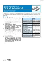
3.3 <strong>THK</strong> Grease pump nozzlesWith a standard or <strong>THK</strong> grease pump (inner thread PT1/8) all sizes of <strong>LM</strong> <strong>Guides</strong> canbe lubricated by using dedicated nozzles. Exclusive attachments are available <strong>for</strong> small<strong>LM</strong> <strong>Guides</strong> so that a suitable attachment can be chosen <strong>for</strong> the model and restrictedspace. The following table shows the different available nozzles:Table 3.3 <strong>THK</strong> Grease pump nozzlesType Dimensions Supported model numbersType N<strong>LM</strong> GuideCam FollowerRod EndModels SSR15,SHS15, SR15, HSR12,HSR15, CSR15,HRW17, GSR15,RSR15, RSH15,HCR12 and HCR15Models CF, CFN andCFHModels PHS5 to 22,RBH and POS8 to 22Type P<strong>LM</strong> GuideModels HSR8, HSR10,HRW12, HRW14,RSR12 and RSH12Type L<strong>LM</strong> GuideModels HSR8, HSR10,HRW12, HRW14,RSR12 and RSH12Type H<strong>LM</strong> GuideBall screwRod EndModels with greasenipple M6F or PT 1/8Models PHS25,PHS30, POS25 andPOS30DedicatednozzleType UDedicated nozzle <strong>for</strong> type N, P, L withinternal thread M5x0.5Note) Types P and L are also capable of greasing less accessible areas other than the model numbersabove (by dropping grease on the raceway).8© <strong>THK</strong> GmbH
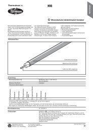
4. <strong>Lubrication</strong> process and handling4.1 General In<strong>for</strong>mationThe grease application must be effected properly according to <strong>THK</strong> specifications.When the <strong>LM</strong> Guide is delivered without grease (only with corrosion inhibition oil) theinitial lubrication quantity must be inserted be<strong>for</strong>e start-up (see chapter 5).When the <strong>LM</strong> Guide is delivered with initial lubrication only the refill quantity should beinserted be<strong>for</strong>e start-up. The initial lubrication quantity is twice the relubrication quantity.These amounts should not be exceeded.In general, it is not recommended to insert the full lubrication quantity during standstillbut to move the carriage at least twice of his length <strong>for</strong>ward and backward after everystroke.Also, when a centralized lubrication system is used the lubrication process should eitherbe executed during operation or in steps of 20% of the recommended lubricationamount. The carriage should be moved at least double of its length. Thus, an optimallubrication dispersion is guaranteed within the carriage and, there<strong>for</strong>e, the piling up ofgrease in the end caps is being avoided.All lubrication equipments should be in a proper and non-corrosive condition.The exact lubrication intervals can only be determined under real operating conditions.The observation period has to be sufficient. If the lubrication interval is too long or thelubricant quantity too low, the colour of the lubricant will change (mostly reddish) at thereverse point of the stroke. In this case take care to lubricate the system immediatelyand change the lubrication interval and quantity.After a longer standstill and be<strong>for</strong>e the restarting of the <strong>LM</strong> Guide the unit has to belubricated with the initial filling lubrication quantity.In case of a lubricant change or replacement (sort or producer), it is necessary to checkwhether the <strong>THK</strong> materials go with the new lubricant and whether the guarantee ofmiscibility is given <strong>for</strong> both lubricants.Please comply with the lubrication specification of the producers, the protection oflabour and the environment. Used and foul lubricants have to be disposed ofappropriately.4.2 <strong>Lubrication</strong> methods<strong>LM</strong> systems can either be lubricated manually by using a grease gun (Fig. 4.2a) or amanual pump or via a centralized lubrication system. The latter method is mainly used<strong>for</strong> machine tools, in which the <strong>LM</strong> system is already provided with a recirculating oil orbath oil lubrication system.In case of a manual centralized lubrication system, several greasing points in onemachine can be provided simultaneously (Fig. 4.2b).An automatic centralized lubrication system ensures in general a smooth and constantlubricant supply (Fig. 4.2c).© <strong>THK</strong> GmbH 9
Fig. 4.2a <strong>Lubrication</strong> with grease gunFig. 4.2b <strong>Lubrication</strong> with centralized hand pumpFig. 4.2c Centralized lubrication system4.2.1 Grease gunA grease gun of which lubrication pressure and flow rate per stroke is not too high mustbe used <strong>for</strong> <strong>LM</strong> <strong>Guides</strong>. It is recommended to use the grease gun MG70 of <strong>THK</strong>.Specifications of the grease gun MG70:Maximal discharge pressure:Discharge rate:p s,max =195 barV s =0.6 cm³/stroke4.2.2 RelubricationWhen pressing the lubricant into the carriage a maximal flow rate may not be exceeded.There<strong>for</strong>e, the minimal discharge time per stroke of the grease gun may not fall below acertain threshold. This time depends on the quantity of lubricant per stroke and thedischarge pressure of the used grease gun.The minimal discharge time (t discharge ) can be calculated with the following <strong>for</strong>mula:max. dischargepressure max. lubricant quantity*245 bar1 cm Hubtdischarge=3per stroke* 2[ s]10© <strong>THK</strong> GmbH
4.2.3 <strong>Lubrication</strong> cycleThe lubrication cycle depends on different conditions (see page 3). The exact lubricationcycles can solely be determined under real operating conditions.The use of the ball/roller chain technology can considerably extend the necessarylubrication cycle compared to conventional <strong>LM</strong> systems. More in<strong>for</strong>mation can be foundin <strong>THK</strong> catalogues/brochures or on the Internet at www.thk.eu.5. Tables of lubrication quantity of different <strong>THK</strong> <strong>LM</strong> <strong>Guides</strong>The following tables show the lubrication quantity of different <strong>THK</strong> <strong>LM</strong> <strong>Guides</strong> be<strong>for</strong>estart-up (initial lubrication quantity). An initial lubrication filling of <strong>THK</strong> <strong>LM</strong> <strong>Guides</strong> isnecessary prior to start running the system. Normally, the initial filling quantity is twicethe relubrication quantity.If <strong>THK</strong> <strong>LM</strong> blocks have no lubrication equipments because of their size, a solution tolubricate the system is to distribute the lubricant directly on the rail.5.1 Initial lubrication quantity: <strong>LM</strong> guide with ball/roller caged technologyFor high dynamic applications (v>2m/s or a>2g) it is advisable to insert the relubricationquantity in several portions and to move the unit while doing this.© <strong>THK</strong> GmbH 11
Tab. 5.1a Type SHS... Tab. 5.1b Type SSR... Tab. 5.1c Type SNR/SNS...Model numberSHSInitiallubrication[cm 3 ]Model numberSSRInitiallubrication[cm 3 ]Model numberSNR/SNSInitiallubrication[cm 3 ]15 0.7 15XV 0.3 25 1.715L 0.9 15XW 0.5 25 L 2.120 1.4 20XV 0.5 30 3.020L 1.8 20XW 0.7 30 L 3.625 2.0 25XV 0.8 35 4.725L 2.4 25XW 1.3 35 L 5.630 3.2 30XW 2.2 45 8.030L 4.2 35XW 3.6 45 L 10.635 3.5 55 9.935L 5.2 55 L 13.045 6.5 65 12.545L 8.5 65 L 17.855 12.3 85 3555L 16.3 85 L 51.165 2265L 29.9Tab. 5.1d Type SHW... Tab. 5.1e Type SRG… Tab. 5.1f Type SRS…Model numberSHWInitiallubrication[cm 3 ]Model numberSRGInitiallubrication[cm 3 ]Model numberSRSInitiallubrication[cm 3 ]12C 0.3 15 0.6 9 0.1512H 0.4 20 1.2 9W 0.1814 0.6 20L 1.5 12 0.2817 0.7 25 2.3 12W 0.3621 0.8 25L 2.8 15 0.5927 1.2 30 3.3 15W 0.7535 3.6 30L 4.2 20 0.6850 8.0 35 3.2 25 1.4435L 4.045 5.845L 7.255 8.155L 10.565L 2112© <strong>THK</strong> GmbH
5.2 Initial lubrication quantity: <strong>LM</strong> guides conventional(without caged ball technology)Tab. 5.2a Type HSR... Tab. 5.2b Type NR/NRS... Tab. 5.2c Type HRW...Model numberHSR/CSR/HCR/JR/HPRInitiallubrication[cm 3 ]Model numberNR/NRSInitiallubrication[cm 3 ]Model numberHRWInitiallubrication[cm 3 ]8 0.01 25 1.5 12 0.0310 0.02 25 L 1.9 14 0.0412 0.06 30 2.5 17 0.215 2.0 30 L 3.2 21 0.320 4.0 35 3.5 27 0.520L 5.0 35 L 4.5 35 1.725 5.0 45 5.0 50 4.225L 6.0 45 L 6.6 60 12.530 7.0 55 9.630L 8.0 55 L 11.835 10.0 65 16.235L 12.0 65 L 22.545 12.0 75 22.945L 14.0 75 L 29.055 17.0 85 36.055L 20.0 85 L 45.365 25.0 100 39.265L 33.0 100 L 55.7Tab. 5.2d Type SR... Tab. 5.2e Type RSR.. Tab.5.2f Type RSR...WModel numberSRInitiallubrication[cm 3 ]Model numberRSRInitiallubrication[cm 3 ]Model numberRSR..WInitiallubrication[cm 3 ]15 V/SB 0.5 5 0.006 3W 0.00415 W/TB 1.0 5N 0.009 3WN 0.00620 V/SB 1.0 7 0.01 5W 0.00620 W/TB 2.0 7N 0.015 5WN 0.00925 V/SB 2.5 9 0.04 7W 0.0225 W/TB 4.0 9N 0.06 7WN 0.0330 V/SB 3.0 12 0.06 9W 0.0430 W/TB 5.0 12N 0.09 9WN 0.0635 V/SB 4.0 15 0.1 12W 0.0635 W/TB 7.0 15N 0.15 12WN 0.0945 W/TB 10.0 20 0.2 15W 0.155 W/TB 12.0 20N 0.3 15WN 0.1570 T 17.0© <strong>THK</strong> GmbH 13
Tab.5.2g Type KR...Tab.5.2h Type GSR...Model numberKRInitiallubrication[cm 3 ]Model numberGSRInitiallubrication[cm 3 ]20... 0.5 15 T 0.326... 1 15 V 0.233...C 1.5 20 T 0.433...A 2 20 V 0.346...C 3.8 25 T 0.746...A 5 25 V 0.555...A 7 30 T 0.965...A 10 35 T 1.0Tab. 5.2i Type HR and HR-TModel numberHR Initial lubrication[cm 3 ]Initial lubrication HR-T[cm 3 ]918 0.06 -1123 0.1 -1530 0.3 -2042 0.8 1.02555 1.9 2.33065 2.5 3.03575 4.2 4.84085 6.3 7.650105 12.4 15.060125 25.7 -14© <strong>THK</strong> GmbH
5.3 Initial lubrication quantity: Ball splinesTab. 5.3a Type LBS/LBST...Model numberLBS/LBST/LBF/LBR/LBH/LBGTab. 5.3b Type LT...Initial lubrication[cm 3 ]Model numberLT/LF/LTR15 0.4 4 0.0320 0.6 5 0.06T 20 0.8 6 0.0825 1.0 8 0.1T 25 1.5 10 0.230 2.0 13 0.3T 30 2.5 16 0.540 5.0 20 0.8T40 5.5 25 1.550 8.5 30 2.5T 50 9.5 40 6T 60 17 50 1070 20 60 20T 70 2585 27T 85 30100 45T 100 55T 120 60T 150 100Initial lubrication[cm 3 ]5.4 : Oil lubrication ; Oil volumeWhen using an oil recirculation greasing system like a <strong>for</strong>ced lubrication, the oil valuesfrom the table below can be used.Tab. 5.4 Oil volume depending on the <strong>LM</strong> sizes <strong>for</strong> all 4 – row ball- and roller <strong>THK</strong> <strong>LM</strong> <strong>Guides</strong>with or without Caged TechnologySizesOil volume <strong>for</strong> oil recirculationsystems cm 3 /10min15 0.0520 0.0520L 0.0525 0.0525L 0.0530 0.0530L 0.0635 0.0735L 0.0845 0.145L 0.155 0.155L 0.1565 0.1565L 0.2© <strong>THK</strong> GmbH 15
<strong>THK</strong> Group – Headquarters <strong>THK</strong> Europe <strong>THK</strong> China<strong>THK</strong> CO., LTD. <strong>THK</strong> GmbH <strong>THK</strong> CHINA CO., LTD.3-11-6 Nishi-Gotanda Hubert-Wollenberg-Str. 13-15 No. 41 Dalian Economic &Shinagawa-ku 40878 Ratingen Technical Development ZoneJ-Tokyo 141-8503 Germany Dalian 116600, ChinaTel.: +81 (0) 3 54 34-03 51 Tel.: +49 (0) 21 02 74 25-555 Tel.: +86 (0) 4 11 87 33-71 11Fax: +81 (0) 3 54 34-03 53 Fax: +49 (0) 21 02 74 25-556 Fax: +86 (0) 4 11 87 33-70 00<strong>THK</strong> U.S.<strong>THK</strong> Southeast Asia & Oceania<strong>THK</strong> America Inc.<strong>THK</strong> <strong>LM</strong> SYSTEM Pte. Ltd.200 East Commerce Drive 38 Kaki Bukit Eunos TechparkSchaumburg, IL. 60173 Singapore 416216Tel.: +1 (0) 8 47 3 10-11 11 Tel.: +65 68 84-55 00Fax: +1 (0) 8 47 3 10-12 71 Fax: +65 68 84-55 50Sales & Support in EuropeTelephoneE-MailDuesseldorf (Germany) +49 (0) 21 02 74 25-0 info.dus@thk.euFrankfurt (Germany) +49 (0) 21 02 74 25 65-0 info.fra@thk.euStuttgart (Germany) +49 (0) 71 50 91 99-0 info.str@thk.euMunich (Germany) +49 (0) 89 37 06 16-0 info.muc@thk.euMilton Keynes (U.K.) +44 (0) 19 08 30 30 50 info.mks@thk.euMilan (Italy) +39 0 39 28 42 079 info.mil@thk.euBologna (Italy) +39 0 51 64 12 211 info.blg@thk.euStockholm (Sweden) +46 (0) 46 8 44 57 630 info.sto@thk.euLinz (Austria) +43 (0) 72 29 51 400 info.lnz@thk.euBarcelona (Spain) +34 (0) 93 65 25 740 info.bcn@thk.euIstanbul (Turkey) +90 (0) 216 362 40 50 info.ist@thk.euPrague (Czech Republic) +420 (0) 24 10 25-100 info.prg@thk.euEindhoven (the Netherlands) +31 (0) 40 74 25-0 info.ein@thk.euLyon (France) +33 (0) 4 37 49 14 00 info.lys@thk.euMoscow (Russia) +7 495 649 80 47 info.mow@thk.euAll data provided has been prepared andchecked carefully. However, we assume no liability<strong>for</strong> any possible errors or omissions. Technical detailsare subject to change.© <strong>THK</strong> GmbHReproduction, even in extracts, shall requirethe prior written consent of <strong>THK</strong> GmbH.16© <strong>THK</strong> GmbH