Shure PSM400 User Guide (English)
Shure PSM400 User Guide (English)
Shure PSM400 User Guide (English)

You also want an ePaper? Increase the reach of your titles
YUMPU automatically turns print PDFs into web optimized ePapers that Google loves.
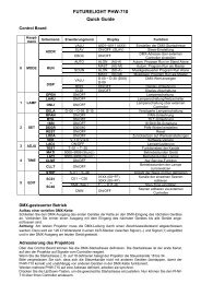
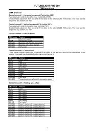
ENGLISHUsing the P4M Personal Monitor MixerDIRECT BOXPans betweenMix Out channelsAUDIOINPUT 1AUDIOINPUT 2AUDIOINPUT 3AUDIOINPUT 41/L(–)2/R(+)Adjust levels toMix OutsMIXOUT 2SPLITOUTPUT 4SPLITOUTPUT 1MIXOUT 1AUX IN1/LSPLITOUTPUT 3AUX IN2/RSPLITOUTPUT 2Once the basic set up is complete, use the P4M Personal Monitor Mixer to create a custom mix:1. Mix the signal from each audio input using the corresponding CONCENTRIC LEVEL/PAN knob:OUTER RING: Use this to pan the signal to the left or right channel of the stereo mix.INNER KNOB: Use this to control the level of the audio input.2. Observe the signal/clip LEDs next to each CONCENTRIC LEVEL/PAN knob.NOTE: Decrease the level of an input if the corresponding signal/clip LED is consistently red. If the level is decreased all the way and theLED remains red, the level of the input from the previous device in the audio chain is too high and should be decreased.3. Up to two additional line-level audio sources (such as other mixers, a click track or a digital sequencer) may be added viathe AUX IN inputs. These signals go directly to the MIX OUT outputs and are not affected by the CONCENTRIC LEVEL/PAN knobs.4. To pass an unaltered signal through the mixer, use the corresponding SPLIT OUTPUT.NOTE: Although the mixer does not provide phantom power for condenser microphones, the SPLIT OUTPUTS can pass phantom powerfrom a phantom power supply to a microphone connected to the corresponding input jack.CAUTION!: Use a “direct box” when connecting guitars, keyboards, and other instruments to a mixing console throughthe P4M Mixer. The phantom power that mixing consoles provide for microphones can damage other instruments. Connectthe instrument to the direct box then connect the direct box to the P4M Mixer input.AUX IN AUX IN MIX OUT MIX OUT2/R 1/L 2/R 1/LSPLIT OUTSSUMSUMLEVPANLEVPANLEVPANLEVPANMIC/LINE INPUTSAudio signal path for the P4M Mixer7
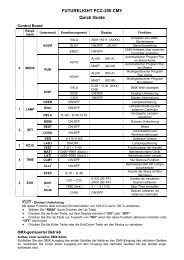
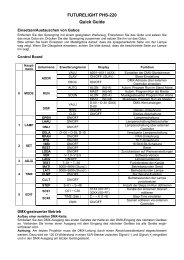
THE P4T TRANSMITTERControls and FeaturesENGLISH1 2 3 4 5TRANSMITTER FRONT PANELPA715 ANTENNA6 7 8 9TRANSMITTER BACK PANEL1. Local Earphone Output Jack (1/8 inch):Connects to earphones.2. Local Earphone Level Control: Adjusts the volume of the localearphone jack’s amplifier. Always listen at low levels.3. Input Level LEDs: Two vertical strings of four LEDs display theinput level of the left and right input channels. The four LEDs onthe left display the status of the signal from channel 1 and the fourLEDs on the right display the status of the signal from channel 2:LEDRED (top)YELLOW (middle)GREEN (bottom two)Signal StatusLimiter ActiveNominal LevelSignal Present4. Transmission Frequency LED: This indicates which of the 16Channels (0–9 or A–F) is transmitting.5. Frequency Select Button: This recessed button changes thetransmission channel. (Use a 1/4” plug to press this button.)6. Antenna Connector 50 , BNC type: This connects to the antennato transmit UHF signals to the receiver.7. LOOP OUT Jacks: Two 1/4” TRS jacks allow the audio signalto pass through the transmitter to other devices, including othertransmitters, tape recorders, or amplifiers. See LOOP Applicationson page 9.8. Input Jacks: Two 1/4” TRS switching jacks are line level audioinputs.9. DC Input Connector: Input for PS40 power supply or P4M mixer’sDC jumper cable.Set-UpFollow these directions to set up the P4T transmitter for operation:1. Plug the mixer’s DC OUT jumper cable into the transmitter’s DC input.2. Attach the antenna to the ANTENNA OUT BNC connector.3. Connect the mixer’s MIX OUT 1/L and MIX OUT 2/R to inputs 1/L and 2/R of the transmitter.4. Select an operating frequency using the FREQUENCY SELECT button. Push the button repeatedly until the LED displays the desired channel.The display will flash. Push and hold the button until the flashing stops to confirm the change (use a 1/4” plug to press the button).IMPORTANT: Never set more than ONE transmitter to the same operating frequency.5. Once the transmitter transmits audio, observe the INPUT LEVEL LEDs. If the LEDs consistently illuminate red, decrease the output level ofthe audio source until the red LEDs only flicker occasionally.6. Set up the P4R receiver as directed in the P4R section of this user’s guide. Make sure that the frequency selected on the receiver matches thefrequency selected on the transmitter.8
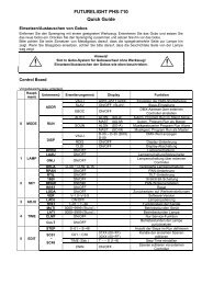
ÑÑÑÑÑÑENGLISHLoop ApplicationsThe LOOP OUT 1/L and 2/R outputs allow the signal going through the P4T transmitter to be routed to other devices. The LOOP feature ofthe transmitter can be used for any number of applications. Shown here are only a few examples of how it can be used. Also see SystemApplication #3.P4T TRANSMITTER(BACK PANEL)P4RReceiverÑ ÑÑÑÑÑÑÑFloor Monitor AmplifierÑÑÑÑÑÑÑ Ñ ÑÑÑÑÑÑRunning Floor Monitors Through a P4T Transmitter: An audio signal can be sent through the LOOP connectors to an amplifier for anonstage monitor system. When setup this way, the P4R and the onstage monitors will reproduce the same audio.BAND MIXSOLO MIX 1SOLO MIX 2SOLO MIX 1BAND MIXAUX 1 AUX 2 AUX 3 AUX 4BAND MIXP4T TRANSMITTERP4R RECEIVERMIXING CONSOLESOLO MIX 2ÑÑÑÑBAND MIXP4T TRANSMITTERBAND MIXP4R RECEIVERSOLO MIX 3SOLO MIX 3BAND MIXP4T TRANSMITTERP4R RECEIVERRunning Multiple PSM Wireless Systems Under MixMode Control: When using a mixer with multiple auxiliary out jacks, a single monitormix can be sent to multiple P4T transmitters using the LOOP connectors, and independent monitor mixes or direct outputs can be sentdirectly to the second channel of each P4T. This allows each P4T user to mix a band mix signal with a solo mix signal using the MixModefeature on the receiver. The thumbwheel on the P4R is used to mix the two signals in relation to one another.Ñ ÑÑÑÑÑÑÑÑÑÑÑÑRunning a Recording Device Through a P4T Transmitter: If you would like to make a recording of a performance, the LOOP outputscan be connected to the inputs of a tape deck, DAT, or other recording device.9
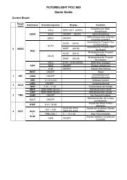
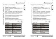
ENGLISHP4R RECEIVERControls and Features19P4R TOP PANEL78FREQ MIXEQLIM234561. Balance Knob: This thumbwheel adjusts the left/right balancewhen the unit is in stereo and the Mix 1/Mix 2 balance whenthe unit is in MixMode.2. SCROLL Pushbutton: Use with the SELECT pushbutton tocontrol the functions in the LCD screen. See Pushbutton Controlson page 10.3. SELECT Pushbutton: Use with the SCROLL pushbutton tocontrol the functions in the LCD screen. See Pushbutton Controlson page 10.4. 1/8” Earphone Output Jack: Connects to earphones.5. Belt Clip: Securely attaches the receiver to a belt, guitar strapor waist band.6. LCD Screen: The LCD Screen displays the status of variousfunctions. See LCD Screen on page 11.7. ON/OFF/VOLUME Knob: Turn clockwise past click to turnON. Continue to turn clockwise to increase volume, counterclockwiseto decrease volume.8. Battery Compartment Door: See Battery Installation onpage 10.9. Antenna: An attached, flexible whip antenna receives radio frequency(RF) from the Transmitter.Battery Installation1. Open the battery compartment door by pushing down and sliding towards the antenna.2. Insert a fresh 9V alkaline battery with the +/– terminals properly positioned.3. Close the battery compartment door.Note: If battery compartment door will not close, the battery is not properly inserted.Set-up1. Turn the ON/OFF/VOLUME knob clockwise past click (ON).2. Check the LCD Screen to see if RF is being received. (see LCD Screen on page 11).3. Plug earphones into earphone output jack. Insert earphones into ears as instructed in the earphone user’s guide.4. Increase the volume slowly until a comfortable listening level is achieved.5. Set the desired functions in the LCD screen as described in LCD Screen on page 11.Pushbutton ControlsPush either the SCROLL or SELECT pushbutton to activate the LCD Screen. Push and hold the SCROLL pushbutton to scroll throughthe functions. The current function is underscored. Use the SELECT pushbutton to change the status of the underscored function.Changing the Reception Channnels1. Push and hold the SCROLL pushbutton.2. Scroll to FREQ.3. Push the SELECT pushbutton to select a channel (0–9 or A–F).NOTE: Use the same reception channel as the P4T transmitter.4. Push the SCROLL pushbutton to confirm changes.Changing MixMode, High Frequency Equalization and Limiter Status1. Push and hold the SCROLL pushbutton. Scroll to the desired function (MIX, EQ, or LIM).2. Push the SELECT pushbutton to toggle the function ON or OFF. A function is ON when a dot appears to the right of the function symbol.3. Push the SCROLL pushbutton to confirm changes.10
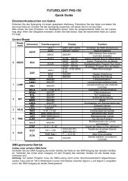
ENGLISHLCD ScreenThe LCD Screen on the top panel displays the status of various functions. The status of these functions can be changed using theSCROLL and SELECT pushbuttons (see Pushbutton Controls on page 10).412FREQMIXEQLIM5631. RF: Indicates the P4R receiver is receiving a transmission.Always check for RF reception prior to inserting earphonesinto ears.2. Battery Life Meter: Indicates the approximate amount of voltageleft in the battery. These voltages translate to time asfollows:HIGH: 4-8 hours of operation.MEDIUM: 1-4 hours of operation.LOW: less than 1 hours of operation.NOTE: If no bars are present within the battery life gauge, changethe battery immediately. Battery life depends on many variables,including battery type (brand), earphones used, and receiver volumesetting.3. RECEPTION CHANNEL (FREQ): The P4R receiver features16 preset, user-selectable channels (0–9 and A–F). The receivermust be set to the same channel as its transmitter.4. MixMode (MIX): The receiver receives the monitor mix in eitherMixMode (MIX ON) or stereo (MIX OFF). See MixMode/Stereo Control on page 12.NOTE: If the receiver is receiving only one signal, it willbe in mono.5. High Frequency Equalization (EQ): Adds 6 dB at 10 KHZ forincreased treble response.6. Limiter (LIM): The limiter provides protection against loudsignals.WARNING! Turning the Limiter OFF defeats protection against hazardous sound levels!Locking Out the LCD ScreenOnce the receiver’s functions are set for use, lock out the LCD screen and pushbuttons to prevent unwanted changes during or betweenperformances. To lock out the front panel:1. Set all functions to desired settings.2. Hold down the SCROLL and SELECT pushbuttons simultaneously for five seconds (A).NOTE: The reception channel will be replaced by dashes (B) when lock-out is engaged.3. When lock-out is engaged, the SCROLL and SELECT pushbuttons light the LCD screen, but cannot change the status of any of the functions.4. To disengage the lock-out, hold the SCROLL and SELECT pushbuttons for five seconds until the reception channel is displayed again.FREQMIXEQLIMAB11
ENGLISHMixMode/Stereo ControlThe flexible design of the PSM 400 Wireless Personal Performance Pack makes configuring a monitor mix very simple. Inaddition, the unique MixMode circuitry enables you to customize your own individual mix in a multiple mix environment.MixMode ControlStereo ControlMono ControlUsed for mixing and combining an individual mix between two distinct monitorsends.Used for conventional stereo monitor mixes.Used when only one (mono) monitor mix is available.STEREOSignal from AudioSource1/L2/R1/L2/RMIXMODESignal from AudioSource1/L2/R1/L and 2/RMIXEDWHAT IS MIXMODE CONTROL?P4T TRANSMITTERP4R RECEIVERThe P4R receiver receives two signals (1/L and 2/R) from the P4T transmitter. The P4R processes these signals in either MixMode or stereo:STEREO: In stereo, the signals remain separate so that 1/L is heard through the left earphone and 2/R is heard throughthe right earphone. The balance knob on the P4R adjusts the balance between the left and right earphones.MIXMODE: In MixMode, the signals are “mixed” in relation to one another using the balance knob, blended into onesignal. The one mixed signal is sent to both the left and right earphones.Using MixModeStep Two: Using the balance knob,the user blends the two signals untilthe correct mix is achieved.MIXMODEchannel 1MIXMODEchannel 2Step Four: The user may continueto adjust the blend usingthe balance knob throughoutthe performance.COUNTERCLOCKWISEMID-POINTCLOCKWISEStep One: The P4Rreceives TWO signalsfrom the P4T transmitter.Step Three: The P4Rsends the mixed signalto both earphones.MIXMODE IN APPLICATIONSMixMode is most useful when two distinct mixes are provided to the P4T transmitter, such as a band mix and a vocal mix. MixMode combinesthese two signals into one monitor mix and allows you to control this mix during the performance using the P4R receiver. For example, if theband overpowers the vocals in the mix, increase the level of the vocals and decrease the level of the band by simply adjusting the balanceknob on the receiver.12
SYSTEM APPLICATIONSAPPLICATION ONE: One PSM 400 SystemENGLISHRF TRANSMISSIONSMIXOUTPUTSP4MPersonal Monitor MixerINPUTS 1–4LEVEL/PANKNOBS 1–4LINEINPUTSP4TTransmitterRF RECEPTIONP4RReceiverThis is the basic configuration of the PSM 400 system and is the recommended configuration for small ensembles in live or rehearsal situations.1. Connect up to four microphones, instruments or audio devices to the four inputs on the P4M mixer front panel.2. Connect MIX OUT 1/L and MIX OUT 2/R on the back panel of mixer to INPUT 1/L and INPUT 2/R on the back panel of theP4T transmitter.3. Mix the four signals using the CONCENTRIC LEVEL/PAN knobs on the front panel of the mixer.4. Transmit the mix to the receiver.APPLICATION TWO: Multiple P4M Personal Monitor Mixers to One P4T TransmitterMIXOUTPUTSP4MAUXINPUTSP4MLINEINPUTSP4TPersonal Monitor Mixer Personal Monitor Mixer TransmitterINPUTS 1–4INPUTS 1–4LEVEL/PANKNOBS 1–4This application, using the P4M’s AUX inputs, allows more than four inputs to be mixed. Recommended for large ensembles in live or rehearsal situations.1. Connect up to four audio sources to the front panel inputs of the P4M mixer.2. Mix these signals using the CONCENTRIC LEVEL/PAN knobs on the mixer.3. Connect the MIX OUTPUTS of the first mixer to the AUX INPUTS of a second P4M mixer.4. Connect up to four more audio sources into the front panel inputs of the second P4M Mixer.5. Mix these signals using the CONCENTRIC LEVEL/PAN knobs on the second mixer.6. Connect the MIX OUTPUTS of the second mixer to the LINE INPUTS of the P4T transmitter. The transmitter receives amix consisting of all eight audio sources, which it transmits to the P4R receiver.NOTE: If more than eight inputs are required, connect additional P4M mixers between the second mixer and the transmitter using theconnection described in step 3 above.13
ENGLISHAPPLICATION THREE: One P4M Mixer/Two P4T TransmittersOther AudioSourcesMix 2/RMonitor MixMixingConsoleTo MixingConsoleLineInputsLOOPOutputsPSMTransmitterPSMRECEIVERMix 1/LSplitOutputsP4MMixOutputsPersonal Monitor MixerInputs 1–4LineInputsPSMTransmitterRF TransmissionRF ReceptionPSMRECEIVERMonitor MixLevel/PanKnobs 1–4This configuration, using the P4M’s SPLIT OUTPUT and a PSM transmitter’s LOOP OUTPUT, allows one P4M to provide custom mixes to two PSM transmitters,and is recommended for small ensembles in live performance:1. Connect up to four microphones or instruments into the P4M inputs. Connect the SPLIT OUTPUTS to a mixing console.2. Connect a monitor mix from a mixing console to the first P4T transmitter.3. On the first PSM transmitter, connect the LOOP output containing the monitor mix to an input on the second PSMtransmitter.4. Connect a MIX OUT output to each transmitters’ remaining input. Use the front-panel PAN knobs to balance input signalsbetween the two transmitters.5. Place the PSM receivers in MixMode. Use the balance wheel on the PSM receiver to blend the monitor mix with the custommix created by the P4M.14
ENGLISHAPPLICATION FOUR: Multiple PSM 400 SystemsOther AudioSourcesTo Mixing ConsoleINPUTSTo Next P4Mor AmplifierMixingConsoleTo Mixing ConsoleINPUTSP4MPersonal Monitor MixerLineInputsP4TTransmitterP4RReceiverShared Mic/Line SignalMonitor MixRF TransmissionMonitor MixSplitOutputs 1-4P4MMixOutputsPersonal Monitor MixerInputs 1–4Level/PanKnobs 1–4LineInputsP4TTransmitterRF ReceptionP4RReceiverThis configuration uses the P4M’s SPLIT OUTPUTS to pass audio signal to other P4M Personal Monitor Mixers. Each player can create a custom mix attheir mixer. Recommended for live, studio or rehearsal situations.1. Connect a monitor mix signal (from a mixing console) and up to three audio sources to the four inputs on the mixer’s front panel.2. Connect the SPLIT OUTPUT of the mixer containing the monitor mix to an input on a second mixer.3. Connect the other SPLIT OUTPUTS from the first mixer to either the second mixer or to the mixing console.4. On the second mixer, connect the SPLIT OUTPUT containing the monitor mix to a third mixer or to a floor monitor amplifier.5. Connect MIX OUT 1/L and MIX OUT 2/R on the back panel of each mixer to INPUTS 1/L and 2/R on the back panel of a P4T transmitter.6. On each mixer, mix the four signals using the CONCENTRIC LEVEL/PAN knobs on the front panel.7. Transmit the mix from each transmitter to its respective P4R receiver.TROUBLESHOOTINGPROBLEMSOLUTIONNo sound at the receiver Check the power cord on the transmitter and make sure it is powered on. Make sure both the transmitter and the receiver are set to the same frequency. Make sure the earphones are plugged in to the receiver. Make sure receiver is on and the battery is good. Listen to the headphone monitor on the transmitter to check audio feed. Make sure the antenna is connected to the transmitter. Check the incoming audio and power connections and the outgoing audioconnections at the mixer.Low receiver range Try to maintain line-of-sight between transmitter and receiver. Try another frequency in case interference is limiting the range. Check for television channel interference.Receiver sounds fuzzy or distorted Make sure no other transmitters are operating on your frequency. Make sure transmitter input level is lighting yellow LEDs for optimum performance. Listen to the headphone monitor on the transmitter to check audio feed.Low audio output at the receiver Make sure transmitter input level is lighting yellow LEDs for optimum performance. Make sure the P4R receiver’s volume knob is up.15
ENGLISHSPECIFICATIONSSystem SpecificationsRF Carrier Frequency Range722 to 865 MHz (country dependent)Operating Range300 ft. (environment dependent)Audio Frequency Response50 Hz to 12 kHz (+/–3 dB); earphone dependentImage Rejection55 dB typicalSpurious Rejection60 dB typicalTotal Harmonic Distortion (1 KHz)0.8% typical (Ref. ±35 KHz deviation)ModulationFM ±35 KHz Deviation (Nominal), MPX StereoChannel Separation35 dB typicalSignal-to-Noise Ratio80 dB typical (A-weighted)Operating Temperature-7° C to +49° C(+20° F to 120° F)P4M Mixer SpecificationsMeasurement Conditions (unless otherwise specified): full gain; 1 KHz, one channel activated; source impedances: Mic 150 Ω, Aux Level 150 Ω;terminations: Line 600 Ω.Frequency Response (Ref 1 KHz, controls centered)20 Hz to 20 Khz ± 2 dBINPUT SpecificationsInput1–4 (front panel) Aux InGain (Maximum) 43 dB 0 dBImpedance (at 1kHz) 5800 Ω 18 kΩ (each)9100 Ω (1/L mono)Input Clipping Level +12dBV +12 dBVCrosstalk -100 dB -90 dBCommon Mode Rejection > 75 dB > 70 dBOUTPUT SpecificationsSplit 1 – 4OutputImpedance N/A 500 ΩMix OutOutput Clipping Level N/A +5 dBV (10 kΩ balancedload, -30 dBV input ch. 1 –4.)Noise (100 Hz to 22 kHz) -110 dBV -100 dBV (all controlsCCW)-62 dBV (all controls CW)Distortion (THD) at 1kHz) .0005% < .05% (0 dBV output)Crosstalk -100 dB -70 dBP4T Transmitter SpecificationsRF Output Power50 mW (+17 dBm) typical conducted (countrydependent)Modulation LimiterInternal peak limiter (>10:1 compression)AntennaExternal whip, 50 Ω BNC connectorLEDs: Resultant Mix Out LevelGreen: -30 dBVYellow: -10 dBVRed: 0dBVCurrent120 mA max.Power RequirementsOperating voltage 14–18 VdcSupplied with one of the following external power supplies: Model PS40: 120 Vac, 60 Hz input. Model PS40E, Model PS40UK: 230 Vac, 50/60 Hz input.NOTE: Courtesy DC connector is protected from short by a self-resetting“Polyfuse”. Maximum recommended load is 250mA (2 P4Ms or 1P4T.)Phantom PowerThe P4M does not produce phantom power, but phantom power is allowedto pass through Split Outputs 1–4 to inputs 1–4 respectively.Audio PolarityAll outputs in polarity with all inputs.XLR Pin 2 is “hot” with respect to Pin 3; Pin 1 is ground.1/4” TRS tip is “hot” with respect to ring; sleeve is ground.Temperature RangeOperating . . . . . . . . . . . . . . . . . . . . . . . . . -7° to 49° C (20° to 120° F)Storage . . . . . . . . . . . . . . . . . . . . . . . . . . -29° to 74° C (-20° to 165° F)Overall Dimensions44 mm H x 218 mm W x 162 mm D(1.72 x 8.60 x 6.37 inches)Net Weight1.20 Kg (2 lbs, 10 oz)Current250 mA maximumDimensions219.2 mm X 43.6 mm X 136.5 mm (8.6 in. X 1.7 in. X 5.4 in.)Net Weight907.2 g (2 lbs., 0 oz.)16
Country CodeCode de PaysLander–KurzelCódigo de paísCodice del PaeseTABLE 1 TABLEAU 1 TABELLE 1 TABLA 1 TABELLA 1P4T–HF(722 – 746 MHZ)P4T–P3(722 – 746 MHZ)P4T–MN(800 – 830 MHZ)P4T–KE(842 – 865 MHZ)A 722 – 746 MHZ * * 800 – 830 MHZ * 842 – 865 MHZ *B 722 – 746 MHZ * * 800 – 830 MHZ * 842 – 865 MHZ *CH 722 – 746 MHZ * * 800 – 830 MHZ * 842 – 865 MHZ *D 722 – 746 MHZ * * 800 – 830 MHZ * 842 – 865 MHZ *E 722 – 746 MHZ * * 800 – 830 MHZ * 842 – 865 MHZ *F * 722 – 746 MHZ * * *GB 722 – 746 MHZ * * * 842 – 865 MHZ *GR 722 – 746 MHZ * * 800 – 830 MHZ * 842 – 865 MHZ *I 722 – 746 MHZ * * * 863 – 865 MHZ*IRL 722 – 746 MHZ * * 800 – 830 MHZ * 842 – 865 MHZ *L 722 – 746 MHZ * * 800 – 830 MHZ * 842 – 865 MHZ *NL 722 – 746 MHZ * * 800 – 830 MHZ * 842 – 865 MHZ *P 722 – 746 MHZ * * 800 – 830 MHZ * 842 – 865 MHZ *DK * * 800 – 820 MHZ * 863 – 865 MHZ*FIN * * 800,1 – 819,9 MHZ * 863 – 865 MHZ*N * * 800 – 820 MHZ * 863 – 865 MHZ*S * * 800 – 814 MHZ * 863 – 865 MHZ*All Other CountriesTous les autres paysAlle anderen LänderDemás paísesTutti gli altri Paesi* * * **Please contact your national authority for information on available legal frequencies for you8r area and legal use of the equipment.*Se mettre en rapport avec les autorités compétentes pour obtenir les informations sur les fréquences autorisées disponibles localement etsur l’utilisation autorisée du matériel.*Für Informationen bezüglich der für Ihr Gebiet verfügbaren gesetzlich zugelassenen Frequenzen und der gesetzlichen Bestimmungenfür den Einsatz der Geräte setzen Sie sich bitte mit der zuständigen örtlichen Behörde in Verbindung.* Comuníquese con la autoridad nacional para obtener información en cuanto a las frecuencias legales disponibles y usos legales delequipo en su área.*Rivolgersi alle autorità competenti per ottenere informazioni relative alle frequenze autorizzate nella propria regione e alle norme cheregolano l’uso di questo apparecchio.83
We, ofDeclaration of ConformityEU DECLARATION OF CONFORMITY<strong>Shure</strong> Incorporated5800 W. Touhy AvenueNiles IL 60714–4608 U.S.A.847–600–2000Declare under our sole responsibility that the following product,Model: P4RDescription: ReceiverHas been tested and found to comply with the limits for an unintentionalradiator device, and approved under the Declaration of Conformityprovision of the Part 15 of the FCC rules.Operation is subject to the following two conditions:1. This device may not cause harmful interference2. This device must accept any interference received, includinginterference that may cause undesired operation.<strong>Shure</strong> Incorporated., Manufacturer.Signed: November 12th, 2003Name, Title: Craig Kozokar, EMCProject Engineer,Corporate Quality, <strong>Shure</strong> IncorporatedWe,of<strong>Shure</strong> Incorporated5800 W. Touhy AvenueNiles, IL 60714–4608, U.S.A.Declare under our sole responsibility that the following productsModel: P4TModel: P4RModel: P4MModel: PS40E, PS40UKDescription: TransmitterDescription: ReceiverDescription: 4–Channel MixerDescription: AC/DC Power AdapterConform to the essential requirements and other relevant previsionsof the R&TTE Directive (1995/5/EC).The products comply with the following product family, harmonized ornational standards:P4T: ETSI EN 300 422–1 ETSI EN 300 422–2ETSI EN 301 489 Part 1 and 9P4R: ETSI EN 300 422–1 ETSI EN 300 422–2ETSI EN 301 489 Part 1 and 9P4M: EN55103–1 EN55103–2PS40E/PS40UK: EN60950, EN6100–3–2, EN6100–3–3Manufacturer: <strong>Shure</strong> IncorporatedSigned: Date: October 27, 2003Name, Title: Craig KozokarEMC Project Engineer, Corporate Quality,<strong>Shure</strong> IncorporatedEuropean Contact: <strong>Shure</strong> Europe GmbHWannäcker Str. 28, 74078 Heilbronn, GermanyPhone: 49–7131–7214–0, Fax: 49–7131–7214–14Note: This equipment has been tested and found to comply with the limits for a Class B digital device, pursuant to part15 of FCC Rules. These limits are designed to provide reasonable protection against harmful interference in a residentialinstallation. This equipment generates, uses and can radiate radio frequency energy and, if not installed and used in accordancewith the instructions, may cause harmful interference to radio communications. However, there is no guarantee thatinterference will not occur in a particular installation. If this equipment does cause harmful interference to radio or televisionreception, which can be determined by turning the equipment off and on, the user is encouraged to try to correct the interferenceby one or more of the following measures:Reorient or relocate the receiving antenna.Increase the separation between the equipmentand the receiver.Connect the equipment into an outlet on acircuit different from that to which the receiveris connected.Consult the dealer or an experienced radio/TVtechnician for help.SHURE Incorporated http://www.shure.comUnited States, Canada, Latin America, Caribbean:5800 W. Touhy Avenue, Niles, IL 60714-4608, U.S.A.Phone: 847-600-2000 U.S. Fax: 847-600-1212 Intl Fax: 847-600-6446Europe, Middle East, Africa:<strong>Shure</strong> Europe GmbH, Phone: 49-7131-72140 Fax: 49-7131-721414Asia, Pacific:<strong>Shure</strong> Asia Limited, Phone: 852-2893-4290 Fax: 852-2893-4055