(DigitalGlobe Logo) DigitalGlobe ®1601 Dry Creek Drive Suite 260Longmont, Colorado, USA, 805035.2 Band-Averaged Spectral Radiance [ W-m -2 -sr -1 -μm -1 ]Band-averaged spectral radiance is defined as the weighted average <strong>of</strong> the peak normalized effective radiance valueover the detector bandpass as shown in the following equation:LλBand=∞∫0L( λ)⋅ R ′(λ)∞∫0R ′(λ)BandBand⋅ dλ⋅ dλwhere Lλ Band is the band-averaged spectral radiance [W-m -2 -sr -1 -μm -1 ] <strong>of</strong> a target to be imaged for a given band,L(λ) is the spectral radiance <strong>of</strong> a target to be imaged, and R′(λ) Band is the relative spectral radiance response for agiven band shown in Figure 2.The second step in conversion to top-<strong>of</strong>-atmosphere spectral radiance is to divide the band-integrated radiance by aneffective bandwidth as follows:LλPixel, Band=LPixel,BandΔλBandwhere Lλ Pixel,Band are top-<strong>of</strong>-atmosphere band-averaged spectral radiance image pixels [W-m -2 -sr -1 -μm -1 ], L Pixel,Bandare top-<strong>of</strong>-atmosphere band-integrated radiance image pixels [W-m -2 -sr -1 ], and Δλ Band is the effective bandwidth[μm] for a given band as provided in the .IMD files (also listed in Table 3 in this document).6 <strong>Radiometric</strong> Balancing for Multiple Scene MosaicsFor many customers, it may be desirable to create large area mosaics from multiple <strong>WorldView</strong>-2 scenes. Ignoringgeometric effects, adjacent areas might appear to have different brightness values (counts) leaving a visible seambetween scenes. As stated earlier, <strong>WorldView</strong>-2 counts are a function <strong>of</strong> the spectral radiance entering the telescopeaperture at the <strong>WorldView</strong>-2 altitude <strong>of</strong> 770km. This top-<strong>of</strong>-atmosphere spectral radiance varies with Earth-Sundistance, solar zenith angle, topography (the solar zenith angle is calculated for flat terrain so topography adds anextra geometry factor for each spot on the ground), bi-directional reflectance distribution function (BRDF-the targetreflectance varies depending on the illumination and observation geometry), and atmospheric effects (absorption andscattering).Topography, BRDF, and atmospheric effects can be ignored for simple radiometric balancing. Consequently themajor difference between two scenes <strong>of</strong> the same area is the solar geometry. The solar spectral irradiance valueslisted in Table 4 correspond to the values for the mean Earth-Sun distance, normal to the surface being illuminated.The actual solar spectral irradiance for a given image varies depending on the Earth-Sun distance and the solarzenith angle during the individual image acquisition. This variation will cause two scenes <strong>of</strong> the same area (oradjacent areas) taken on different days to have different radiances and hence different image brightnesses. Thedifference can be minimized by correcting imagery for Earth-Sun distance and solar zenith angle. Before applyingthis correction, the solar geometry must be determined for each scene to be used in the mosaic.Release Date: 01 November 2010 Revision 1.0©Copyright 2010, DigitalGlobe ® , Inc. 10
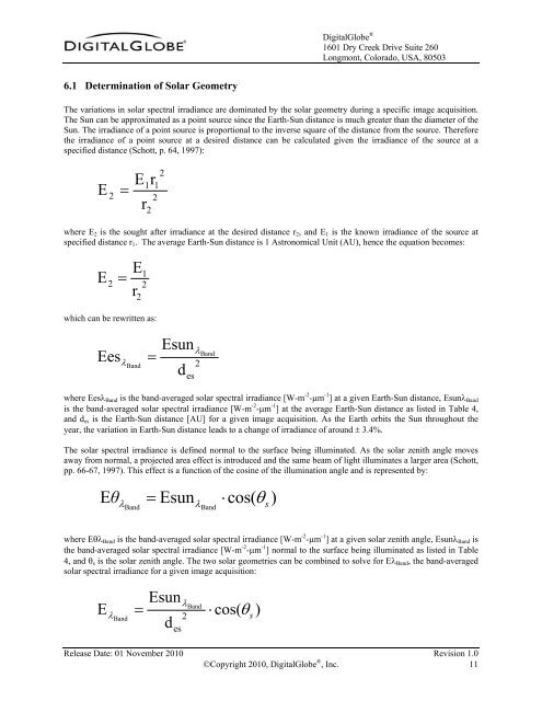
(DigitalGlobe Logo) DigitalGlobe ®1601 Dry Creek Drive Suite 260Longmont, Colorado, USA, 805036.1 Determination <strong>of</strong> Solar GeometryThe variations in solar spectral irradiance are dominated by the solar geometry during a specific image acquisition.The Sun can be approximated as a point source since the Earth-Sun distance is much greater than the diameter <strong>of</strong> theSun. The irradiance <strong>of</strong> a point source is proportional to the inverse square <strong>of</strong> the distance from the source. Thereforethe irradiance <strong>of</strong> a point source at a desired distance can be calculated given the irradiance <strong>of</strong> the source at aspecified distance (Schott, p. 64, 1997):E =2E21r122rwhere E 2 is the sought after irradiance at the desired distance r 2 , and E 1 is the known irradiance <strong>of</strong> the source atspecified distance r 1 . The average Earth-Sun distance is 1 Astronomical Unit (AU), hence the equation becomes:E =2Er122which can be rewritten as:Eesλ=BandEsunλ2d esBandwhere Eesλ Band is the band-averaged solar spectral irradiance [W-m -2 -μm -1 ] at a given Earth-Sun distance, Esunλ Bandis the band-averaged solar spectral irradiance [W-m -2 -μm -1 ] at the average Earth-Sun distance as listed in Table 4,and d es is the Earth-Sun distance [AU] for a given image acquisition. As the Earth orbits the Sun throughout theyear, the variation in Earth-Sun distance leads to a change <strong>of</strong> irradiance <strong>of</strong> around ± 3.4%.The solar spectral irradiance is defined normal to the surface being illuminated. As the solar zenith angle movesaway from normal, a projected area effect is introduced and the same beam <strong>of</strong> light illuminates a larger area (Schott,pp. 66-67, 1997). This effect is a function <strong>of</strong> the cosine <strong>of</strong> the illumination angle and is represented by:EθλBand=EsunλBand⋅cos(θ )swhere Eθλ Band is the band-averaged solar spectral irradiance [W-m -2 -μm -1 ] at a given solar zenith angle, Esunλ Band isthe band-averaged solar spectral irradiance [W-m -2 -μm -1 ] normal to the surface being illuminated as listed in Table4, and θ s is the solar zenith angle. The two solar geometries can be combined to solve for Eλ Band , the band-averagedsolar spectral irradiance for a given image acquisition:Esun=dλEλBand2esBand⋅ cos( θ )sRelease Date: 01 November 2010 Revision 1.0©Copyright 2010, DigitalGlobe ® , Inc. 11


