(DigitalGlobe Logo) DigitalGlobe ®1601 Dry Creek Drive Suite 260Longmont, Colorado, USA, 805033 Gain SettingsAssuming the detectors have a linear response as a function <strong>of</strong> input radiance, the equation <strong>of</strong> a straight line can beused for the camera equation:DN = L ⋅ Gain + OffsetDet, BandDet,BandDet,BandDet,Bandwhere DN Det,Band is the raw image digital number value[counts], L Det,Band is the target spectral radiance [W-m -2 -sr -1 -μm -1 ], Gain Det,Band is the absolute gain [counts / W-m -2 -sr -1 -μm -1 ], and Offset Det,Band is the instrument <strong>of</strong>fset [counts].Rather than calibrate an absolute gain for each individual detector, a single gain is determined for each band, andthen each detector is scaled relative to the other detectors in the same band. Separating the absolute and relativegain as described, one arrives at the following expression:DN = L ⋅ Gain ⋅ B + OffsetDet, BandDet,BandBandDet,BandDet,Bandwhere Gain Band is the absolute gain [counts / W-m -2 -sr -1 -μm -1 ] for each band and B Det,Band is the relative detector gain[unitless]. By definition, the average relative gain equals one. To conform to the nomenclature carried out throughthe rest <strong>of</strong> this technical note, DN Det,Band will be redefined as p Det,Band , L Det,Band* Gain Band will be redefined as q Det,Band ,and Offset Det,Band will be redefined as A Det,Band . The above equation then takes the form:p = q ⋅ B + ADet, BandDet,BandDet,BandDet,Bandwhere p Det,Band are raw detector data [counts], q Det,Band are radiometrically corrected detector data [counts] which arelinearly scaled to spectral radiance, B Det,Band is the detector relative gain, and A Det,Band is the dark <strong>of</strong>fset [counts].The gain settings for <strong>WorldView</strong>-2 Pan and MS bands are dependent on the following conditions: band, TDIexposure level, line rate, pixel aggregation, and bit depth <strong>of</strong> product. The appropriate absolute gain values, takinginto account the combination <strong>of</strong> these parameters, are provided with each product in the image metadata (.IMD fileextension).The product image bands, line rate, and aggregation, are set based on the operating mode (see Table 1). The bitdepth for <strong>WorldView</strong>-2 products can be 8 or 16 bits. The TDI setting for a given image is selected using a look-uptable based on the estimated solar elevation angle for the image acquisition. No land cover information is taken intoaccount in setting the TDI level. The values in the look-up table were chosen to maximize the radiometric resolution<strong>of</strong> <strong>WorldView</strong>-2 while minimizing the number <strong>of</strong> saturated pixels in an image.4 <strong>Radiometric</strong> Correction <strong>of</strong> <strong>WorldView</strong>-2 ProductsRelative radiometric calibration and correction are necessary because a uniform scene does not create a uniformimage in terms <strong>of</strong> raw digital numbers (DNs). Major causes <strong>of</strong> non-uniformity include variability in detectorresponse, variability in electronic gain and <strong>of</strong>fset, lens fall<strong>of</strong>f, and particulate contamination on the focal plane.These causes manifest themselves in the form <strong>of</strong> streaks and banding in imagery. In the case <strong>of</strong> a pushbroom systemfocal plane containing linear arrays, the data from every pixel in a given image column comes from the samedetector. Any differences in gain or <strong>of</strong>fset for a single detector show up as a vertical streak in raw imagery.Differences in gain and <strong>of</strong>fset for a single readout register show up as vertical bands as wide as the number <strong>of</strong>detectors read out by the register. Relative radiometric correction minimizes these image artifacts in <strong>WorldView</strong>-2products.A relative radiometric correction is performed on raw data from all detectors in all bands during the early stages <strong>of</strong><strong>WorldView</strong>-2 product generation. This correction includes a dark <strong>of</strong>fset subtraction and a non-uniformity correctionRelease Date: 01 November 2010 Revision 1.0©Copyright 2010, DigitalGlobe ® , Inc. 6
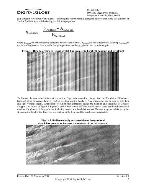
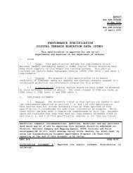
(DigitalGlobe Logo) DigitalGlobe ®1601 Dry Creek Drive Suite 260Longmont, Colorado, USA, 80503(e.g. detector-to-detector relative gain). Isolating the radiometrically corrected detector data in the last equation <strong>of</strong>Section 3, this is accomplished using the following equation:qDet,Band=pDet,BandB− ADet,BandDet,Bandwhere q Det,Band are radiometrically corrected detector data [counts], p Det,Band are raw detector data [counts], A Det,Band isthe dark <strong>of</strong>fset [counts] for a specific image acquisition, and B Det,Band is the detector relative gain.Figure 4: Raw desert image (visual stretch has been set to highlight banding and streaking)To illustrate the concept <strong>of</strong> radiometric correction, Figure 4 is a raw desert image from the <strong>WorldView</strong>-2 Pan band.Gain and <strong>of</strong>fset differences between readout registers result in banding. Non-uniformities can be seen as both darkand light vertical streaks. Application <strong>of</strong> radiometric correction causes the banding and streaking to virtuallydisappear, as shown in Figure 5. Figures 4 and 5 each have a different visual stretch based on the minimum andmaximum brightness <strong>of</strong> the pixels (not including masked and invalid detectors). The raw image stretch is set by thestreaks so the detail <strong>of</strong> the desert has less contrast in the figure and the streaks are exaggerated.Figure 5: <strong>Radiometric</strong>ally corrected desert image (visualstretch has been set to increase the contrast <strong>of</strong> the desert scene)Release Date: 01 November 2010 Revision 1.0©Copyright 2010, DigitalGlobe ® , Inc. 7