total station w-800 series
total station w-800 series
total station w-800 series

You also want an ePaper? Increase the reach of your titles
YUMPU automatically turns print PDFs into web optimized ePapers that Google loves.
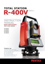
TOTAL STATIONW-<strong>800</strong>SERIESBASICINSTRUCTIONMANUALW-821NXW-822NXW-823NXW-825NXW-835NXTI Asahi Co., Ltd.International Sales Department4-3-4 Ueno Iwatsuki-Ku, Saitama-ShiSaitama, 339-0073 JapanTel.: +81-48-793-0118Fax. +81-48-793-0128E-mail: International@tiasahi.comwww.pentaxsurveying.com/en/
Before using this product, be sure that you have thoroughly read andunderstood this instruction manual to ensure proper operation.After readingthis manual, be sure to keep in a convenient place for easy reference.This Basic Instruction Manual contains the basic operation procedures and precautions onW-<strong>800</strong> <strong>series</strong> hardware.W-<strong>800</strong> <strong>series</strong> is an open platform product and you can enjoy variety of application software on it.Regarding the operations of application software, please refer to their respective manuals.Copyright © 2012 TI Asahi Co.,Ltd.TI Asahi Co.,Ltd. makes no warranty, expressed or implied, including but not limited to any impliedwarranties or merchantability or fitness for a particular purpose, regarding these materialsand makes such materials available.
PRECAUTIONS REGARDING SAFETYSafety Precautions (Must be followed)The following items are intended to prevent possible injury to the user or other people and/ordamage to the instrument before it occurs. These safety precautions are important to the safeoperation of this product and should be observed at all times.Distinctive displaysThe following displays are used to distinguish precautions by the degree of injury or damagethat may result if the precaution is ignored.WARNINGItems indicated by this display are precautions which, if ignored, would result in serious injury.CAUTIONItems indicated by this display are precautions which, if ignored, may result in injury ormaterial.• Here “injury” refers to injuries such as cuts, burns or electric shock the treatment of whichwill not likely require hospitalization or long-term attention.• “Material damage” refers to damage to facilities, buildings, acquired data, etc.Before using this product, be sure that you have thoroughly read and understood this instructionmanual to ensure proper operation. After reading this manual, be sure to keep it in a convenientplace for easy reference.This instrument complies with the protection requirement for residential and commercial areas.If this instrument is used close to industrial areas or transmitters, the equipment can be influencedby electromagnetic fields.WARNINGDo not stare into the laser beam directly as this may result in damage to your eyes.W-<strong>800</strong> is a Class IIIa (3R) Laser product.Do not look into the laser radiation aperture directly as this may result in damage to your eyes.Never use the telescope to view intense light such as direct sunlight or sunlight reflectedthrough a prism as this may result in loss of sight.Do not disassemble, modify or repair this product as there a risk of laser radiation.Do not aim the laser beam at a person as it is harmful to the eyes and body. Receive theexamination treatment by the doctor when the eyesight or body trouble is doubted byany chance.1
• Electro-Magnetic Compatibility (EMC): This instrument complies with the protectionrequirement for residential and commercial areas. If this instrument is used close to industrialareas or transmitters, the equipment can be influenced by electromagnetic fields.• Do not use this product in a coal mine, in a location where there is coal dust, or near flammablematerial as there is a risk of explosion.• Do not disassemble, modify or repair this product as there is a risk of fire, electric shock andburn injury. If you think the product requires repair, contact the retail outlet where you purchasedit or an authorized repair site.• Only use the battery charger intended for this product as the battery charger.Use of another battery charger entails a risk of fire or burn injury from the battery burstinginto flames due to possible differences in voltage or polarity.• Do not use a damaged electric cord plug or loose electric outlet when charging as there isa risk of fire or electric shock.• Do not charge the battery while covered by clothes or similar item as there is a risk of fire ifthe clothes ignite.• Do not use the battery or charger when wet as there is a risk of fire and burn injury due toshort-circuit.• To prevent making short-circuit when removing the battery and charger from the case andstoring them, apply electrically resistant tape to the poles of the battery. Storing the batteryand charger as it may result in fire or burn injury due to short-circuit.• Do not throw the battery into fire or expose it to heat as there is a risk of injury if it explodes.CAUTIONFor your safety, perform the initial and periodical inspection as well as when the instrumentis fixed and adjusted.When the laser beam enters eyes, an unexpected accident might be caused by blink ofeyes. Do not place the laser product at a height where its laser beam may hit the eyes ofcar drivers and pedestrians.Do not place the laser product at a place where its laser beam may hit a reflecting objectsuch as a mirror or a glass window. The reflection beam of the laser is also harmful to thehuman body.When not performing measurement, cut off the power supply or shade the Objective lenswith Objective cap to prevent the instrument emitting the laser beam.Keep the laser product in the place where the person who does not have the productknowledge such as children does not touch by mistake.Before disposing of the instrument, destroy its power supply mechanism to prevent itfrom emitting the laser beam.2
• Do not remove the handgrip without good reason. If it does come off, be sure to attach itsecurely to the instrument with screws. If it is not fastened securely, the instrument may fallwhen you grasp the handgrip, leading to possible injury.• Do not short the poles of the battery or charger as there is a risk of injury or fire.• Do not touch any fluid which may leak from the battery as there is a risk of chemical burninjury or reaction.• Do not insert or remove the electric plug with wet hands as there is a risk of electric shock.• Do not use the case to stand on as it is slippery and unstable and may cause you to fall,resulting in possible injury.• Be sure the tripod itself and the instrument on the tripod are both installed securely as insecureinstallation may cause the tripod to fall over or the instrument to drop, resulting in possibleinjury.• Do not carry the tripod with the metal shoe pointing toward another person as it may injurehim/her.• The instrument contains a rechargeable battery and a battery charger.• It may be illegal to dispose the battery at the end of its useful life.• Check with your local solid waste officials for details for recycling.[Usage precautions]Surveying instruments are high-precision instruments. In order to assure that the Electronic TotalStation W-<strong>800</strong> <strong>series</strong> product which you have purchased will provide long-lasting maximum performance,the precautions in this manual must be followed. Be sure to follow these instructionsand use this product properly at all times.[Solar observation]WARNINGNever view the sun directly using the telescope as this may result in loss of sight.Never point the objectivelens directly at the sun as this may damage internal components. When using the instrument forsolar observation, be sure to attach the specially designed solar filter (MU64) to the objective lens.[Laser beam]Do not stare into laser beam. W-<strong>800</strong> <strong>series</strong> is a Class IIIa (3R) Laser product.[EDM axis]The W-<strong>800</strong> <strong>series</strong> EDM is the red visible laser beam and the beam diameter is very small. Thebeam is emitted from the objective center and the base plate center hole. The EDM axis isdesigned to coincide with the telescope sight axis (but both axes may deviate slightly becauseof intense temperature changes and a long time lapse).[Target constant]Confirm the Target Constant of the instrument before measurement.If a different constant is to be used, use the correct constant of the target. The constant is storedin the instrument's memory when turned off.3
[Reflectorless and reflector sheet]Reflectorless measurement precautions:• The measurement range and accuracy of Reflectorless are based on the condition that laserbeam is emitted perpendicular to the white side of the Kodak Gray Card. There is a possibilitythat the range may vary when the target does not satisfy the conditions above at surveywork. The measurement range may be influenced by the shape of the target and itsenvironment.• There is a possibility that the instrument may not be able to correctly calculate out the distancewhen receiving reflected laser beam from forth and back directions in case of measuringthe target on the road.• There is a possibility that measured distance may be longer or shorter than the actual onewhen measuring a target of slope or sphere or rugged shape as the distance is calculatedout from synthesized values.• There is a possibility that the instrument may not be able to correctly calculate out the distancewhen receiving reflected laser beam from a man or a car that comes and goes in frontof the target.• There is a possibility that the distance may not be correctly measured when measuring atarget in the direction where there is a reflecting object (mirror, stainless board and whitewall, etc.) or under too strong sun light.• In a situation high accuracy may not be expected, perform the measurement by reflectorsheet or prism.• The measurement range at TRACK mode is over 5m.• It may take longer time than usual when measuring the distance exceeding 300m or thedistance to an object that is hard to measure.Reflector sheet measurement precautions:• There is a possibility that correct distance measurement may not be performed by dispersionor reduction of laser beam when the laser beam comes into the target from diagonalangle.• When using reflector sheet, set the reflector sheet to have its surface be perpendicular tothe aiming line. If it is positioned not to be perpendicular, there is a possibility that correctdistance measurement may not be performed by dispersion or reduction of laser beam.[Battery & charger]• Do not use any batteries and battery chargers other than those PENTAX assured adequate.• If water should happen to splash on the instrument or the battery, wipe it off immediately andallow it to dry in a dry location. Do not put the instrument in the case until it is completely dryas this may result in damage to the instrument.• Turn off the power when removing the battery from the instrument as removing the batterywhile the power is still on may result in damage to the instrument.• The battery mark displayed on the instrument is only an estimate of remaining batterypower and is not completely accurate. Replace the battery quickly when it is about to runout as the time a battery lasts on one full charge differs depending on conditions ofambient temperature, and the measurement mode of the instrument.• Confirm the battery level remaining before operating.4
[Auto focus]The Auto focus mechanism is very precise but will not function under every condition. Focusingdepends on brightness, contrast, the shape and size of the target. In such a case, press the AF buttonand focus on the target by operating the Power focus key or the Focus ring.[LD POINT, laser pointer]When making a correct direction using the “LD POINT”, aim the laser beam at the wall and markthe center and then confirm the discrepancy between the reticle center and the marked pointbeforehand.[Interface]Do not insert or remove SD card, CF card and USB Connector outdoors.Be careful not to let dust, mud, sand, water, harmful gas or salty steam enter the card slot or USBconnector port. Be sure to turn the instrument’s power off before inserting or removing the SDcard, CF card or USB Connector.[Touch panel]Use the Stylus pen when you touch the panel for operation of software.Do not touch the panel with any things such as fingertips or pen point as this may scratch anddamage the screen.[Data saving]When using application software, store data in SD card drive, CF card drive or DiskOnChip folder.Data stored in other drives is deleted when the power is turned OFF.[Storage and operating environment]• To prevent making short-circuit when removing the battery and charger from the case andstoring them, apply electrically resistant tape to the poles of the battery. Storing the batteryand charger as is may result in fire or burn injury due to short-circuit.• Avoid storing the instrument in places subject to extreme high, low or radicallyfluctuating temperature. (Ambient temperature range during use: –20° C to +50° C)• Distance measurements may take longer when atmospheric conditions are poor such aswhen heat shimmer is present. When storing the instrument, always put it in its case andavoid storage in dusty location or location subject to vibration or extreme heat or humidity.• Whenever there is a sharp temperature difference between the instrument’s storage andusage environment, allow the instrument to adjust to the environment for an hour or morebefore using it. Be sure to protect the instrument from the sun if the location is subject tointense direct sunlight.• During surveys for which the survey precision or atmospheric measurement method hasbeen defined measure the atmospheric temperature and pressure separately and enterthose values rather than using the Automatic Atmospheric Correction function.• The battery should be charged approximately once per month if the instrument is to be storedfor an extended period of time. The instrument should also be removed from its caseoccasionally and aired out.• In addition to these precautions, be sure to handle the instrument properly at all times followingthe descriptions given in the various sections of this manual to assure safe and propermeasurements.5
[Transporting and carrying the instrument]• Be careful to protect this instrument from shock of impact and excessive vibration whichmay result in damage during transportation and shipment.• When transporting the instrument, always put it in the case and wrap shockabsorbingmaterial around it and be sure it is handled as “FRAGILE”.[Checks and repairs]• Always check the instrument before beginning work and check that the instrument is maintainingthe proper level of precision. Pentax bears absolutely no responsibility for damagesdue to survey results obtained from surveys conducted without an initial instrument check.Never disassemble the instrument, battery or charger even if you do detect an abnormalityas there is a risk of fire or electric shock due to short-circuit.If you think the product requires repair , contact the retail outlet where you purchased it oran authorized repair site.• Never disassemble the instrument, battery or charger even if you do detect an abnormalityas there is a there is a risk of fire or electric shock due to short-circuit, If you think the productrequires repair, contact the retail outlet where you purchased it or an authorized repair site.6
CONTENTSPRECAUTIONS REGARDING SAFETY 1SAFETY PRECAUTIONS (MUST BE FOLLOWED) 1USAGE PRECAUTIONS 31. BEFORE USING THE INSTRUMENT 91.1 NAMES OF PARTS 91.2 UNPACKING AND PACKING 101.3 STANDARD EQUIPMENT 101.4 ATTACHING AND CHARGING THE BATTERY 111.5 INSERTING / REMOVING SD CARD 141.6 INSERTING / REMOVING CF CARD 151.7 CONECTING USB CABLE 161.8 INTERNAL MEMORY 171.9 DETACHING / ATTACHING STYLUS PEN 172. DISPLAY AND KEYBOARD 182.1 DISPLAY AND KEYBOARD 182.2 OPERATION KEYS 182.3 ALPHANUMERIC INPUT 192.4 LD POINT, LASER POINTER 193. PREPARATION FOR SURVEYING 203.1 CENTERING AND LEVELING OF THE INSTRUMEN 203.2 LASER PLUMMET 213.3 LEVELING WITH CIRCULAR VIAL 223.4 EYEPIECE ADJUSTMENT 233.5 TARGET SIGHTING 243.6 ATTACHMENT AND DETACHMENT OF TRIBRACH 284. CHECKS AND ADJUSTMENTS 294.1 ELECTRONIC VIAL 294.2 CIRCULAR VIAL 304.3 VERTICAL RETICLE 314.4 PERPEND CULARITY OF LINE OF SIGHT TO HORIZONTAL AXIS 324.5 VERTICAL 0 POINT ERROR 324.6 LASER PLUMMET 334.7 OFFSET CONSTANT 334.8 BEAM AXIS AND LINE OF SIGHT 344.9 THE EDM BEAM AXIS 347
1. BEFORE USING THE INSTRUMENT1.1 Names of partsTop handleCollimatorFocus ringPower focus keyAF butonEyepiece ringInstrument height markEyepieceBattery latchLaser indicatorBattery packCirculator vialTelescope tangent screwCF card slotTelescope clamp screwDisplay panelClamp screwKey boardTangent screwRS-232C connectorSD card slotLeveling screwUSB connectorBase plateDetaching knobObjective lensA shift fixed screw is attached to Base plate of a shift base type model.9
1.2 Unpacking and packing[Unpacking the Instrument from the case]Å Set the case down gently with the lid facing upwards.Ç Open the latches while pressing down on the lock (safety mechanism) and open the lidof the case.É Remove the instrument from the case.[Packing the Instrument in the case]Å Make sure the telescope is fairly level and lightly tighten the telescope clamp screw.Ç Line up the housing marks (round yellow marks on the instrument) and tighten theupper and lower clamp screws.É With the housing marks facing upward,set the instrument gently in the case without forcing it.Ñ Close the lid to the case and secure the latches.1.3 Standard equipment• Instrument• Carrying case• BP02 battery• BC03/AC01 charger• Plumb bob• Hexagonal wrench• Rain cover• Quick Reference Guide• CD10
1.4 Attaching and charging the battery[Removing the Battery]ÅÇTurn the Battery latch anticlockwise and remove the battery pack.Lift up the battery pack and remove it from the instrument.• Be absolutely sure to turn the power off when removing the battery pack as removingthe battery pack while the power is still on may result in damage to the instrument.[Attaching the battery]ÅÇAlign the guide grooves on the battery pack with the guide grooves on the instrumentand push the top of the battery pack into place.Turn the Battery latch clockwise to fix.• Turn and fix the Battery latch to lock the battery pack while in use11
[Charging the battery]• The battery BP02 is not charged at our factory shipment. It must be changed before use.• For BP02 charge, use the special BC03 charger.[Connection of code]Å Insert the output plug of the power supply code in Jack of the AC adaptor.Ç Insert the output plug of the AC adaptor in Jack of the charger.É Insert the power supply plug of the power supply code in the outlet of AC power supply.[Installation of battery]Å Draw the battery to the lock lever side and put it on the battery pocket.The battery is firmly installed on the battery pocket.Ç Press down the battery and then slide it to the opposite direction of the lock lever.É The lock lever goes up, and the battery is fixed.Ñ Under such a condition, if “Connection of the code” is done, the charge with the batteryis begun.[Detaching the battery]Å Press the lock lever and slide the battery to the lock lever direction.Ç Detach the battery packing from the battery pocket.12
[Display panel]Ñ Installation lampÇ Charge lampÅ Power supply lampÉ Discharge lampÖ Discharge buttonÅ Power supply lamp (red): Turns on when the power supply is turned on.Ç Charge lamp (green): Turns on while charging and turns off when the charge iscompleted.É Discharge lamp (yellow): Turns on when you push the discharge button.Turns off when the discharge is completed.Ñ Installation lamp (red): Blinks or turns on when the battery packing is attachednormally.Blinks when charge or discharge and turns on when charge iscompleted.(The charge lamp in the lower does not blink and does notturn on)Ö Discharge button: Discharge lamp lights when you push this button, and thedischarge of battery begins.[How to charge]Å It begins charging automatically when you set the battery packing in the charger whichbeams the power supply lamp.Ç Leave just as it is until the charge is completed.É When the charge is completed, the charge lamp is turned off.Ñ Detach the battery packing from the charger when the charge is completed.[Refreshing the battery]The use time shortens gradually by the phenomenon of “Effect of the memory” when the NiMHbattery leaves capacity and repeats the charge.The voltage recovers after refreshing and the usetime returns normally in such a battery. Please refresh one degree every five times of the charge.[Refreshing]Set the battery in the charger as well as the case of the charge. Push the electrical dischargebutton. The electrical discharge lamp lights and the electrical discharge begins.The electrical discharge lamp is turned off when the electrical discharge ends, the charge lamplights, and the charge starts automatically. Leave just as it is until the charge is completed. Whenthe charge is completed, the charge lamp is turned off. Detach the battery from the charger.[Time of refreshing and charge]Battery BP02 is discharged from the state of a full charge at about 960 minutes and the chargeis completed from the electrical discharge at about 130 minutes. However, the electrical dischargetime is proportional to the remainder capacity of the battery. Moreover, the time required forrefreshing might be different from the above-mentioned time according to a surrounding temperatureand the state of the battery.13
1.5 Inserting / removing SD card• Be sure to turn the instrument’s power off before inserting or removing the SD card.Inserting SD card1) Open the Slot cover2) Insert the SD card into the slot. (The side with terminal should face the instrument andthe cut-off corner should be up).3) Insert the SD card to the end. Be sure not to press the card too hard.After the SD card is inserted, close the Slot cover completely.Removing SD card1) Open the Slot cover2) Lightly press the SD card so the card pops out.3) After the SD card is removed, close the Slot cover completely.• Do not open/close the Slot cover or insert/remove the SD card outdoors.14
1.6 Inserting / removing CF card• Be sure to turn the instrument’s power off before inserting or removing the CF card.Inserting CF card1) Unlock the CF card slot cover by pressing ‘CF OPEN’ button, then, open the cover.2) Carefully insert the CF card into the Slot until the Inject button pops out.(The side with terminal must face the instrument)3) After the CF card is inserted, close the Slot cover completely.Insert the CF card with its tubfacing the instrument.• Do not open / close the Slot cover or insert / remove the CF card outdoors.15
Removing CF card1) Unlock the CF card slot cover by pressing ‘CF OPEN’ button, then, open the cover.2) Press the Inject button so the CF card pops out.3) After the CF card is removed, close the Slot cover completely.1.7 Connecting USB cable• Be sure to turn the instrument’s power off before connecting ordisconnecting the USB Cable.1) Open the USB connector cover2) Insert the USB connector into the USB port in right direction.3) After the USB is disconnected, close the USB connector cover completely.Be sure the direction of USBmini B connector is same asthat of the USB port.• Do not open/close the USB connector cover or connect/disconnect the USB cable outdoors.16
1.8 Internal memoryW-<strong>800</strong>’s internal memory stores data in a folder named DiskOnChip in /MyComputer.Be sure not to connect W-<strong>800</strong> and a PC with USB cable and transfer the stored files in theDiskOnChip or delete the file using the PC.1.9 Detaching / attaching Stylus penStylus pen is attached behind the LCD unit.Touch panel inputSelection of functions can be done by touching the display with Stylus pen. Do not touch thedisplay with any things such as fingertips or pen point. Otherwise it may cause malfunction ordamage to the display.17
2. DISPLAY AND KEYBOARD2.1 Display and keyboardESC keyLaser andElectronic vial keyIllumination keyPower keyAlphanumericand +/- keyENT keyFunction keyCursor control key2.2 Operation keysKeyDescriptionUsed to turn ON/OFF power supplyUsed to return to previous screen or cancels an operation.Used to turn ON/OFF the illumination of the LCD display.Used to accept the selected (highlighted) choice or value displayed on the screen.[LASER]Used to operate the functions such as Laser plummet,electronic vial and Laser pointer.[Alphanumeric] Used to input alphabets and numerical value.Used to display the data 1 page back or 1 page ahead.Used to move the cursor up or down.Used to move the cursor left or right18
2.3 Alphanumeric inputThe point name is inputted by the Alphanumeric keys as following.Key Letter under Key Letter & Figure order to input[ 0 ] [ @] [ . ] [ _ ] [ - ] [ : ] [ / ] [ 0 ][ 1 ] PQRS [ P ] [ Q ] [ R ] [ S ] [ p ] [ q ] [ r ] [ s ] [ 1 ][ 2 ] TUV [ T ] [ U ] [ V ] [ t ] [ u ] [ v ] [ 2 ][ 3 ] WXYZ [ W ] [ X ] [ Y] [ Z ] [ w] [ x ] [ y ] [ z ] [ 3 ][ 4 ] GHI [ G] [ H] [ I ] [ g ] [ h ] [ i ] [ 4 ][ 5 ] JKL [ J ] [ K] [ L] [ j ] [ k ] [ l ] [ 5][ 6 ] MNO [ M] [ N] [ O ] [ m] [ n ] [ o ] [ 6 ][ 7 ] [ ] [ ? ] [ ! ] [ _ ] [ ¯¯¯ ] [ ^] [ I ] [ & ] [ 7 ][ 8 ] ABC [ A] [ B ] [ C ] [ a ] [ b ] [ c ] [ 8 ][ 9 ] DEF [ D] [ E ] [ F ] [ d ] [ e ] [ f ] [ 9 ][ . ] [ . ] [ , ] [ : ] [ ; ] [ #] [ ( ] [ ) ][ +/- ] [ + ] [ - ] [ * ] [ / ] [%] [ = ] [ < ] [ > ]2.4 LD POINT, Laser PointerHow to activate/terminate the laser beam emission differs depending on application software.For exact method of activating/terminating laser beam emission, refer to the instructions in themanuals of respective software.• The Laser indicator is turned on and theLaser pointer function is operating.mark on the left of the screen blinks while the• The beam of the sun is strong and visual confirmation is difficult in daytime when outdoors.• The laser beam is designed not to be able to observe through the telescope.• Please visually align the laser beam to the target and mark the center. Confirm the alignment(horizontal and vertical) before measuring when performing accurate work like stakeout when using the Laser pointer function.• Please do not look at the laser source of beam directly.19
3. PREPARATION FOR SURVEYING3.1 Centering and leveling of the instrument[Setting up the instrument and the tripod]ÅÇÉÑAdjust the tripod legs so that a height suitable for observation is obtained when theinstrument is set on the tripod.Hang the plumb bob on the hook of the tripod, and coarse center over the <strong>station</strong> onthe ground. At this time, set the tripod and fix the metal shoes firmly into the groundso that the tripod head is as level as possible, and the plumb bob coincides with the<strong>station</strong> on the ground.If the tripod head is mis-leveled by the action of fixing the metal shoes into the ground,correct the level by extending or retracting each leg of the tripod.Setting up and turn on.20
3.2 Laser plummetÖTurn on the laser plummet function.How to activate/terminate the laser beam emission differs depending on applicationsoftware. For exact method of activating/terminating laser beam emission, refer to theinstructions in the manuals of respective software.The brightness adjustment step of the laser is 10 steps.ÜMatch the position by the tripod so that the laser mark coincides with the ground mark.Rotate the instrument by 90°, and confirm the vial of the the electronic vial is at the centerat any position. Correct the bubble with the leveling screw when the bubble comes offfrom the center.• The laser plummet spot can become difficult to see in bright sunlight which makes itdifficult to perform the occasional check. In this case, use your foot or the carrying case tomake a shadow over the laser position.• The laser plummet is adjusted to be within +/- 0.5 mm at the instrument height of 1.5m atfactory shipping.• Please do not look at the laser source of beam directly.21
3.3 Leveling with circular vialTripod is adjusted according to the following points by extending or contracting the legs so thatthe bubble of the Circular vial goes to the center of the circle.• Shorten the leg at the side of the bubble or extend the leg opposite of the bubble toposition the bubble in the center of the vial circle.• All three legs are extended or contracted until the bubble is in the center.During this process, the foot is not placed on the tripod leg point and the position of thetripod points do not change.ÅÇÉÑÖÜRotate instrument horizontally and make twoLeveling screws arbitrarily chosen parallel to the display.Turn on the Electronic vial function.Put the bubble of the Circular vial in the center of thecircle when the display shows “TILT OVER”.Turn two Leveling screws arbitrarily chosen in anopposite direction mutually and put the vial of thehorizontal Electronic vial in the center. (Figure A)Put the bubble of the lengthwise Electronic vial inthe center by operating the Leveling screw of oneremainder. (Figure B)The procedures are different according to the state ofthe Automatic inclination correction as following.Confirm whether the plummet is on the ground mark.When you confirm it is not on the mark, loosen the center screw and move the instrumentover the ground mark correctly and fix the instrument by a center screw. Repeatfrom Å to Ü[When using the Automatic inclination correction by 2 axis]Please read procedure Ü because the horizontal angle and the perpendicular angle error bya perpendicular axis are automatically corrected.[When using the Automatic inclination correction by 1 axis]The instrument is horizontally rotated by 180° after the bubble of the Electronic vial is adjustedon the center at a Left circle position side and confirm that the bubble of the vial is at the centerat the right circle position.[When using without Automatic inclination correction]Confirm the bubble is at the center even if the instrument is rotated by each 90°.[Note]Display or indication of the electronic plummet vary depending on the software to be installed.For more details, please refer to the user manual of the application software.22
3.4 Eyepiece adjustmentThe eyepiece adjustment is performed before target sighting.ÅÇÉRemove the telescope lens cap.Point the telescope at a bright object, and rotate the eyepiece ring full counter-clockwise.Look through the eyepiece, and rotate the eyepiece ring clockwise until the reticleappears as its maximum sharpness.• When looking into the eyepiece, avoid an intense look to prevent parallax and eye fatigue.23
3.5 Target sighting[Auto focus]The Auto focus mechanism is very precise but will not function under every condition.There is aslight possibility of focusing failure owing to brightness, contrast, the shape and size of thetarget. In such a case, press the AF button and focus on the target by operating the Power focuskey or the Focus ring.No contrast like a white wallBright back lightObstacle in front of a targetA wall composed ofsingle horizontal lines24
[Target sighting by Auto focus]The Auto focus of W-<strong>800</strong> <strong>series</strong> has following two modes.1. Normal mode: Pressing AF button focuses on the target.2. Continuous mode: Pressing AF buttons for two seconds beeps, and releasing the key entersinto the Continuous mode. This mode enables you to perform the Autofocus approx. for one minutes only by sighting through the telescopeand following the target.Normal modeContinuous modePress the AF button.Press AF buttons for twoseconds until it beeps andrelease the key.[Auto focus: Target sighting by Normal mode]ÅÇÉÑÖÜLoosen the telescope clamp and horizontal clamp screws.Point the telescope at the target using a collimator.Tighten the above two screws.Adjust the eyepiece.Look through the telescope and press the AF button. Move your eye vertically andhorizontally to see if the target image moves in relation to reticle.Align the reticle accurately on the target using telescope and horizontal tangent screws.CollimatorTargetCollimatorAF buttonTarget sighting• If the target image does not move, there is no parallax. If it moves, eliminate the parallax.• Even when vertical angle measurement is not performed, it is recommended that thetarget should be placed at the reticle center.• Operating the Power focus key rotates the Focus ring, so do not touch it while it is rotating.25
[Auto focus :Target sighting by Continuous mode]ÅÇÉÑÖÜáLoosen the telescope clamp and horizontal clamp screws.Point the telescope at the target using a collimator.Tighten the above two screws.Adjust the eyepiece.Look through the telescope and then press the AF button for two seconds to beep,and release the key to enter into the Continuous mode.Align the reticle accurately on the target using telescope and horizontal tangent screws.Point the telescope to the next target as well.CollimatorTargetCollimatorAF buttonPress AF buttons for twoseconds until it beepsandrelease the key.Target sighting• Keep the target close to the reticle center when following it by the Continuous mode.• Continuous mode automatically ceases after approx. one minute.• Pressing the AF button or operating the Power focus key releases the continuous mode.• Operating the Power focus key rotates the Focus ring, so do not touch it while it is rotating.26
[Auto focus :Target sighting by Power focus mode]ÅÇÉÑÖÜLoosen the telescope clamp and horizontal clamp screws.Point the telescope at the target using a collimator.Tighten the above two screws.Adjust the eyepiece.Look through the telescope, and then operate the Power focus key and focus on the target.Align the reticle accurately on the target using telescope and horizontal tangent screws.CollimatorTargetCollimatorPower focus keyTarget sighting• Tilting the Power focus key “clockwise” makes it possible to focus on closer objects and“counterclockwise” will focus on farther objects.• Tilting angle of the Power focus key makes it possible to perform following three focusing speeds.Low speed: When tilted to middle position by approx. 5 degreesMiddle speed: When tilted fully by approx. 10 degreesHigh speed: When tilted fully by approx. 10 degrees and passed one second• Operating the Power focus key rotates the Focus ring, so do not touch it while it is rotating.27
[Target sighting by manual focus]ÅÇÉÑÖÜLoosen the telescope clamp and horizontal clamp screws.Point the telescope at the target using a collimator.Tighten the above two screws.Adjust the eyepiece.Look through the telescope and then rotate the Focus ring and stop it where the targetcan be seen clearly and the target image does not move in relation to reticle even if youreye is vertically and horizontally moved.Aligh the reticle accurately on the target using telescope and horizontal tangent screws.CollimatorFocus ringTargetCollimatorTarget sighting• The Focus ring rotation “clockwise” makes it possible to focus on closer objects and“counter clock wise” will focus on further objects.3.6 Attachment and detachment of tribrachThe tribrach of W-821NX,W-822NX,W-823NX, and W-825NX are detachable from the instrumentif required when replacing the instrument with a target or unit prism for example.[Detachment]First loosen the recessed screw with a screwdriver, then rotate the locking knob until the arrowpoints upward, and lift the instrument up.[Attachment]Mount the instrument on the tribrach with the guide marks coinciding, and rotate the lockingknob until the arrow points downward. The guide and guide mark must be fitted to attach theinstrument. When the tribrach does not need to be attached or detached or instrument is to betransported, tighten the recessed screw with a screwdriver to fix the locking knob.28
4. CHECKS AND ADJUSTMENTS• Checks and Adjustments should be performed before and during measurement.• The instrument should be checked after long storage and transportation.• The checks should be performed in the following order.[Cautions on CHECKS AND ADJUSTMENTS]• When adjustment is completed, be sure that adjusting screws are completely tightened. Whenfinishing turning adjusting screws, be sure that screws are turned in a direction for tightening.• Repeat check after adjustment, and check if the instrument has been adjusted properly.• When adjustment is completed, be sure that adjusting screws are completely tightened.When finishing turning adjusting screws, be sure that screws are turned in a direction fortightening.4.1 Electronic vial[Checks]Å Align the Electronic vial in parallel with a line joiningany two of the leveling screws. Then, adjust the twoscrews to center the bubble in the Electronic vial.Ç Turn two leveling screws in an opposite directionmutually and have the bubble of the side of theelectronic vial to the center.É Make the bubble of the length of the electronic vialto the center by operating the leveling screw of oneremainder.Ñ Rotate the instrument by 180° and confirm theposition of the bubble of the electronic vial. At thistime, it is not necessary to adjust it if the bubble ofthe electronic vial is in the vicinity of the center.• Please check the electronic vial in a steady environment that has no vibration or rapidtemperature change.• When the electronic vial is checked outdoors and on a tripod, avoid sunlight influence byusing a sunshade. Please wait for a while until the instrument and tripod are at the sametemperature as the surrounding air.• When the instrument is seen at the position of “Left circle”, movement and the inclination of theinstrument become the same on the screen in the electronic vial. Please note that themovement of the bubble becomes opposite direction if it is seen at the position of “Right circle”.[Adjustments]It is necessary to adjust as following when the bubble is not in the vicinity of the center in theconfirmation of Ñ .29
4.2 Circular Vial[Checks]Å Adjust by the electronic vial beforehand.Ç Confirm the position of the bubble of the Circular vial.At this time, it is not necessary to adjust if the bubble is at the center of the circle.[Adjustments]When the bubble of the Circular vial comes off from the center according to check procedure Ç,it is necessary to adjust. Turn the bubble adjustment screw with a hex wrench (L type wrench)and put the bubble in the center of the circle.[Only the detaching type model]Turn the bubble adjustment screws with the reticle adjustment pin and put the bubble in thecenter of the circle.• Tighten the screws equally after the above adjustment.30
4.3 Vertical reticle[Checks]Å Set the instrument up the tripod and carefully level it.Ç Sight the target Point A with telescope.É Using the telescope fine adjustment screws, move Point A to the edge of the field of viewby screw (point A’).Ñ No adjustment is necessary if Point A moves along the vertical line of the reticle.[Adjustments]Å If Point A is off from the vertical line of the reticle, first remove the eyepiece cover.Ç Using the adjusting pin, loosen the four reticle adjustment screws slightly looseningeach screw by the same amount, and then rotate the reticle line around the sight axisand align the vertical line of the sight axis with Point A’.É Tighten the reticle adjustment screws again by the same amount, and repeat the checkto make sure the adjustment is correct.* Since the W-821NX, W-822NX and W-823NX have triple axis compensation, it is necessaryto make other settings besides the adjustments mentioned above.For details, contact the dealers from whom the instrument was purchased.31
4.4 Perpendicularity of Line of sight to horizontal axis[Checks]Å Position a target Point A at a distance 30m - 50m away from the instrument, and sight itwith the telescope.Ç Loosen the telescope lock screw and turn the telescope until a point is sighted at a distance roughly equal to that of Point A. This is Point B.É With the telescope still reversed loosen the horizontal lock screw and rotate theinstrument around the vertical axis, and sight Point A again.Ñ Loosen the telescope lock screw and turn the telescope until a point is sighted at adistance equal to that of Point B. This is Point C.Ö No adjustment is necessary if Point B and C are aligned.[Adjustments]Å If Points B and C are not aligned, mark Point D at 1/4 the length of the BC, fromPoint C in the direction of Point B.Ç Using the adjustment pin, rotate the reticle adjustment screws horizontally oppositeeach other (see preceding page), and move the reticle to sight Point D.É Repeat the check and make sure the adjustment is correct.* Since the W-822NX and W-823NX have triple axis compensation, it is necessary to makeother settings besides the adjustments mentioned above.For details, contact the dealers from whom the instrument was purchased.4.5 Vertical 0 point errorBe sure to follow check procedures mentioned below after making adjustments on reticle andperpendicularity of line of sight to horizontal axis.[Checks]Å Set up the instrument and turn the power on.Ç Sight the telescope at any reference target A at Normal state. Read the vertical angle ().É Turn the telescope and rotate the alidade. Sight the same target A again at Back stateand read the vertical angle R.Ñ If +R = 360°, no further adjustment is necessary.[Adjustments]If the deviation d (+ R - 360° ) is wide, contact your local dealer.32
4.6 Laser plummet[Checks]Å Set the instrument on the tripod, and place a piece of white paper with a cross drawn onit right under the instrument.Ç Press the [LASER] key, and move the paper so that the intersecting point of the crosscomes to the center of the Laser mark.É Rotate the instrument around the vertical axis, and observe the center mark positionagainst the intersecting point of the cross at each 90° rotation.Ñ If the Laser mark always coincides with the intersecting point, no adjustment is necessary.[Adjustments]When a center part where a cross intersection and the laser mark look the brightest shifts by0.5 mm or more (at the instrument height 1.5m), it is necessary to adjust it. A repair engineerdoes this adjustment. Please contact the PENTAX dealer.4.7 Offset constantThe offset constant rarely changes. It is recommended, however, that check be done once ortwice a year. The check of the offset constant can be done on a certified base line. It can also beobtained in a simple way as described below.[Checks]1. Locate points A, B and C at about 50m intervals on even ground.2. Set up the instrument at point A, and measure the distances between AB and AC.3. Set up the instrument at point B, and measure the distance BC.4. Obtain the offset constant (K):K = AC - (AB+BC)[Adjustments]• Contact your local dealer for adjustment of the off-set constant when the K is not nearly 0.33
4.8 Beam axis and line of sightBe sure to check that the beam axis and line of sight are aligned when the adjustments onreticle and perpendicularity of line of sight to horizontal axis are made.[Checks]Å Set the prism at a distance greater than 50 m.Ç Accurately sight the center of the prism through the telescope.É Turn the power on and press [MEAS] to measure.Ñ No adjustment is necessary if beam receiving buzzer sounds immediately andmeasurement value is displayed in a few seconds.[Adjustments]• If instrument function is not as described in Ñ, contact your local dealer.• This check should be done under good weather conditions.4.9 The EDM beam axisThe distance measurement (EDM) beam axis is adjusted to be aligned to the sighting axis of thetelescope, but it can be changed a little in case of rapid temperature change, shock or aging.Check your instrument by following procedures.[Checks]Å Install the instrument on the tripod and level it at the distance of approx.50 m from the wall.Ç Displace the target plate attached to the end of this manual. Place the target plate adjustingits center to the center of telescope cross line and to be about horizontal to the instrument.É Turn the power on and set target type to ‘Reflector sheet’.Ñ When starting measurement, the laser spot is will appears on the target.The adjustment is not necessary if the center of the laser spot stays within 10 mmfrom the center of the target.[Adjustments]At the procedure 4. above, if the “Center” of laser spot is not within the internal circle (10mm) ofthe target plate, the adjustment is necessary. Please contact your PENTAX dealer.34
5. SPECIFICATIONSModel W-821NX W-822NX W-823NX W-825NX W-835NXTelescope Magnification 30xEffective aperture45mm (EDM 45mm)Resolving power 3.0”Field of view2.6% (1° 30')Minimum focus1.0 mFocusAuto focus / Power focus / ManualDistance measurement Laser class Visible Laser: Class IIIa (3R) (Reflectorless)/ Class II (2) (Prism. sheet)Measurement range (Good condition) 3Reflectorless 11.5 ~ 550mReflectorsheet 21.5 ~ 600m (<strong>800</strong>m)Mini Prizm1.5 ~ 2500m (3000m)1P1.5 ~ 7000m (9000m)3P1.5 ~ 9000m (9999m)Accuracy 4 Prism / Reflector Sheet 1.5m ~ 10m: ± (3+2ppm x D)mm10m ~ : ± (2+2ppm x D)mm)Reflectorless1.5m ~ 300m: ± (5+2ppm x D)mm300m ~ : ± (7+10ppm x D)mmAt Auto-ATM. CorrectionPrism / Reflector SheetReflectorless1.5m ~ 10m: ± (3+10ppm x D)mm10m ~ : ± (2+10ppm x D)mm)1.5m ~ 300m: ± (5+10ppm x D)mm300m ~ : ± (7+18ppm x D)mm0.1mm (Fine mode), 1mm (Normal mode), 10mm (Track mode)Minimum countMeasurement time 5Repeat meas. Normal (1mm): Prism, Ref.sheet 2.0sec. Ref.less 2.0sec.Quick (1mm):Prism, Ref.sheet 1.2sec. 6Track (10mm): Prism, Ref.sheet 0.4sec. Ref.less 0.4sec.Initial meas. Normal (1mm): Prism, Ref.sheet 2.5sec. Ref.less 2.4sec.Quick (1mm):Prism, Ref.sheet 1.7sec. 6Track (10mm): Prism, Ref.sheet 2.5sec. Ref.less 2.5sec.Angle measurementMeasuring methodAbsolute Rotary encoderDetection methodVertical / Horizontal angle: 2 sidesMinimum count1” / 5” selectableAccuracy (ISO 17123-3) 1” 2” 3” 5”Compensator 3 axis 72 axisTangent screw 2 speed 1 speedSensitivity of vialsPlate level (electronic)30”/1div.Circular level8’/2mmPlummetVisible Laser, ±0,5mm (instrument height 1.5m)Base Detachable ShiftingDust and Water ProtectionIP54 (instrument only)Ambient temperature-20°C ~ 50°C / -4°F ~122°F (Working range)Tripod thread 5/8” x 11 35mm P2Dimensions / WeightDimension197(W) x 347 (H) x 217 (L)mmWeight (incl. Battery) 6.3 kg 6.2 kgCarrying case380(W) x 292 (H) x 475 (L)mm / 3.2 kgBattery pack BP02Power sourceNi-MH 4300mAh (Rechargeable), DC6.0VOperation timeApprox. 7 hours (single measurement every 30 seconds)Weight380gBattery charger BC03 and AC Adapter AC01Input voltage (AC01)AC 100 ~ 240VOutput vultage (BC03)DC7.5VWeight280g35
Model W-821NX W-822NX W-823NX W-825NX W-835NXData Processor CPU, Clock frequency Intel® XScale, 400MHzOS Microsoft® Windows® CE.NET 4.2Application softwareSelectableInternal memorySDRAM = 64MBFLASH = 128MB (built-in)Memory card2GB (Max) 8I/FRS-232C , CF Type II , SD CARD , USBDisplay / KeyboardDisplay type3.7 inch, Color LCD, 640x480 pixels 9with back light and touch panel functionQuantity 2 1 (2nd optional)Keys33 each (12 numeric / 11 function / 10 special)Display back lightIntensity settings: 10 stepsLaser PointerYesDate clockYes[Note]123456789The measurement range and accuracy of reflectorless, and time required to measure mayvary by the shape, size of surface area and reflection rate of the target and its environment.The measurement range of reflectorless is determined by the white side of the Kodak GrayCard.Reflector sheet: PENTAX genuine Reflector sheetThe measurement range may vary by conditions of the environment.Normal conditions: 20km visibility with slight shimmerGood conditions: 40km visibility, overcast, no heat, no shimmer and moderate wind.When automatic atmospheric correction is on, the EDM error is 10ppm in prism andreflector sheet mode.EDM measuring time is determined in good conditions. It may takes longer than usual tomeasure the distance exceeding 4000m in prism mode and 300m in reflectorless mode.Quick mode, which functions with prism and reflector sheet, is effective only under normalmode(1mm) and up to 500m.In addition to dual-axis correction in the (X) and (Y) direction, mechanical error in theinstrument is corrected.Memory card is not supplied with the instrument.Depending on application software.Remarks:The brand names mentioned in the specifications are a trademark or aregistered trademark of each company.36
6. APPENDIX6.1 Atmospheric correctionThe speed at which light travels through the air varies depending on the temperature andatmospheric pressure.The W-<strong>800</strong> <strong>series</strong> is designed to measure distances at the speed of light inorder to measure accurately, atmospheric correction needs to be used. The instrument isdesigned to correct for weather conditions automatically if the temperature and pressure areinput. Correction is then carried out based on the following formula.K: Atmospheric Correction ConstantP: Atmospheric pressure (hPa)t: Temperature(°C)Distance after Atmospheric Correction D = Ds (1+K)Ds: Measured distance when no Atmospheric Correction is used.6.2 hPa and mmHg conversion table[Converting from hPa to mmHg][Converting from mmHg to hPa]37
6.3 Error when no atmospheric correction is madeWhen measurement is carried out with no Atmospheric Correction (with the settings fixed at atemperature of 15°C and an atmospheric pressure of 1013 hPa or 760 mmHg), the Error per 100meters in temperature and pressure will be shown in the tables below.• When the actual pressure is 1013 hPa (760 mmHg) and the temperature is 25°C, conductingthe measurement with the temperature left at 15°C will result in the measurement beingshort by 0.9 mm per 100 meters.[Error table: When hPa (15°C, 1013hPa as standard)][Error table: With mmHg (15°C, 760mmHg as standard)]38
6.4 Atmospheric refraction and earth curvature correction• Atmospheric refraction and earth curvature correction refers to correcting both thebending of the light beam caused by atmospheric refraction and the effect on the heightdifferential and horizontal distance caused by the earth curvature.• Correction called “atmospheric refraction and earth curvature correction” is initiated tocorrect error when the slope distance and vertical angle are caused to determine thehorizontal distance and the height differential, with this instrument, the following formulais used to correct these factors.• Calculation formula when atmospheric refraction and earth curvature correctionparameter is set to “ON”:Corrected horizontal distance (H)Corrected vertical distance (V)• Calculation formula when atmospheric refraction and earth curvature correctionparameter is set to “OFF”:S: Slope distance: Vertical angle from horizontalK: Atmospheric refraction coefficient (0.14 or 0.2)Re: Diameter of earth 6378137m39
6.5 Distance rangeGenerally speaking, the maximum range which can be measured varies considerably dependingon the atmospheric conditions. For this reason, the Specifications illustrate the values for bothGood and Normal weather conditions. It is extremely difficult to judge when weather conditionsare “Good” and when they are “Normal”. With this instrument, the conditions noted below areused to differentiate between the two situations, (Good weather conditions for surveying aredifferent from Normal weather conditions, and in surveying situations, cloudy skies areconsidered more favorable than sunny skies.)Weather conditions for measurement ranges are based on the following standard values:Normal:Good:Visibility of approximately 20 km, with slight shimmer and moderate wind.Visibility of approximately 40 km, overcast, with no shimmer and moderate wind.40
7. NOTICE TO THE USER OF THIS PRODUCTTICE TO THE USER OF THIS PRODUCTTo assure compliance with the Safety standard 21 CFR, Chapter 1. Subchapter J. The U.S. bureauof Radiological Health requires the following information to be provided to user:It can be dangerous to look into the beam with optical equipment such as binoculars and telescopes.1. Specifications of Laser RadiationA) The EDM module of the W-<strong>800</strong> <strong>series</strong> produces a visible light beam, which is emitted fromthe telescope objective lens and the center hole of the instrument base plate.The W-<strong>800</strong><strong>series</strong> is designed and built to have a laser diode radiating at 620-690 nm.B) Radiant powerThe W-<strong>800</strong> <strong>series</strong> is designed and built to radiate a maximum average radiant power of4.75mW from the telescope, and 0.95mW from the center hole of the base plate.The usermay be subject to this radiation as a beam while operation until such time that the instrumentis turned off.2. The following labels are affixed to and must remain attached to this laser product.A) The following Certification label is located near the Plate level.:“This laser product is complied with the provisions of 21 CFR 1040. 10 and 1040.11.For a Class IIIa (3R) laser product.”B) Caution label is located near the exit aperture:“AVOID EXPOSURE Laser radiation is emitted from this aperture.”C) Warning logotype is located on the surface of the telescope:“DANGER LASER RADIATION AVOID DIRECT EYE EXPOSURE”D) Warning label is Located near the exit aperture.3. Caution to maintain the safety in compliance with the standardA) To maintain the safety standard, refrain from any operation, maintenance, or adjustmentother than described in this instruction manual.B) Operation, maintenance or adjustment other than those specified in this instructionmanual may result in hazardous radiation exposure.C) Maintenance and repair not covered in this manual must be done by an authorizedPentax dealer.D) How to activate/terminate the laser beam emission differs depending on applicationsoftware. For exact method of activating/terminating the following types of laser beamemission, refer to the instructions in the manuals of respective software.1) Laser beam emission by the Distance measurement2) Laser beam emission by the Laser pointer3) Laser beam emission by the Laser plummet41
[TARGET PLATE]42
TI Asahi Co., Ltd.International Sales Department4-3-4 Ueno Iwatsuki-Ku, Saitama-ShiSaitama, 339-0073 JapanTel.: +81-48-793-0118Fax. +81-48-793-0128E-mail: International@tiasahi.comwww.pentaxsurveying.com/en/Printed in BelgiumJapan Surveying Instruments Manufacturers’ AssociationMember symbol of the Japan SurveyingInstruments Manufacturers’ Associationrepresenting the high qualitysurveying products.Copyright © 2013 TI Asahi Co., Ltd. All rights reservedThe duplication, reuse or sale of any information provided on this manual including but notlimited to images, is strictly prohibited without expressed permission from the copyright owners.01.2013 W<strong>800</strong>-Basic01A