StreamPro ADCP Operation Manual - global site
StreamPro ADCP Operation Manual - global site
StreamPro ADCP Operation Manual - global site
- No tags were found...

You also want an ePaper? Increase the reach of your titles
YUMPU automatically turns print PDFs into web optimized ePapers that Google loves.
<strong>StreamPro</strong> <strong>ADCP</strong><strong>Operation</strong> <strong>Manual</strong>Click http://www.rdinstruments.com/smartlink/sp/index.shtml to get the latestdocumentation changes, Field Service Bulletins, FAQ's, and Product News!P/N 95B-6003-00 (February 2008)
Table of Contents1 Introduction....................................................................................................................................... 11.1 How to Contact Teledyne RD Instruments..........................................................................................11.2 Notice of Compliance..........................................................................................................................21.2.1 Date of Manufacture ...........................................................................................................................21.2.2 Environmental Friendly Use Period (EFUP)........................................................................................21.2.3 WEEE .................................................................................................................................................21.2.4 CE.......................................................................................................................................................21.2.5 Material Disclosure Table ...................................................................................................................31.3 Conventions Used in <strong>Manual</strong>s ............................................................................................................42 <strong>StreamPro</strong> Overview......................................................................................................................... 52.1 Inventory .............................................................................................................................................52.2 Visual Inspection of the <strong>StreamPro</strong>.....................................................................................................52.3 <strong>StreamPro</strong> Overview...........................................................................................................................63 <strong>StreamPro</strong> Care................................................................................................................................. 73.1 General Handling Guidelines ..............................................................................................................73.2 Assembly Guidelines ..........................................................................................................................73.3 Deployment Guidelines.......................................................................................................................74 <strong>StreamPro</strong> Assembly........................................................................................................................ 85 <strong>StreamPro</strong> Communications Setup .............................................................................................. 115.1 Creating a Bluetooth Shortcut ...........................................................................................................115.2 Establish a Bluetooth Connection .....................................................................................................126 Testing Your <strong>StreamPro</strong> <strong>ADCP</strong> .....................................................................................................147 Troubleshooting ............................................................................................................................. 158 <strong>StreamPro</strong> Maintenance................................................................................................................. 178.1 Spare Parts.......................................................................................................................................178.2 Transducer Assembly .......................................................................................................................198.3 Solar Shield Removal .......................................................................................................................208.4 Battery Replacement ........................................................................................................................208.5 Electronic Housing Cover Plate Removal .........................................................................................228.6 <strong>StreamPro</strong> Re-assembly...................................................................................................................238.6.1 Cover Plate O-Ring Inspection and Replacement.............................................................................238.6.2 Battery Compartment O-Ring Inspection & Replacement.................................................................248.6.3 Electronic Housing Cover Plate Replacement ..................................................................................258.7 Solar Shield Replacement.................................................................................................................268.8 Desiccant Bags .................................................................................................................................268.9 Storage and Shipping Maintenance ..................................................................................................278.9.1 Removal of Biofouling .......................................................................................................................278.9.2 Transducer Head Inspection.............................................................................................................288.9.3 Final Storage.....................................................................................................................................288.9.4 Shipping Preparation ........................................................................................................................308.10 Returning <strong>StreamPro</strong> <strong>ADCP</strong>s to TRDI for Service ............................................................................318.10.1 Domestic Shipments .........................................................................................................................318.10.2 International Shipments ....................................................................................................................329 <strong>StreamPro</strong> Commands................................................................................................................... 349.1 Data Communication and Command Format....................................................................................349.1.1 Command Input Processing..............................................................................................................349.1.2 Data Output Processing....................................................................................................................359.2 Firmware Upgrades ..........................................................................................................................369.3 Feature Upgrades .............................................................................................................................409.3.1 How to Install the Long Range Feature Upgrade ..............................................................................419.4 Command Descriptions.....................................................................................................................44
9.4.1 Miscellaneous Commands................................................................................................................44? – Help Menus.................................................................................................................................449.4.2 Control System Commands ..............................................................................................................45CK - Keep Parameters......................................................................................................................45CR – Retrieve Parameters................................................................................................................45CS – Start Pinging (Go) ....................................................................................................................469.4.3 Environmental Commands................................................................................................................47EC - Speed of Sound ........................................................................................................................47ES – Salinity......................................................................................................................................47ET - Temperature..............................................................................................................................48EX – Coordinate Transformation.......................................................................................................48EZ - Sensor Source ..........................................................................................................................499.4.4 Performance and Testing Commands ..............................................................................................50PS – Display System Parameters .....................................................................................................50PT - Built-In Tests .............................................................................................................................51PT0 - Help.........................................................................................................................................51PT2 – Show Sensors ........................................................................................................................51PT3 - Receive Path...........................................................................................................................529.4.5 Timing Commands............................................................................................................................53TS – Set Real-Time Clock.................................................................................................................539.4.6 Water Profiling Commands ...............................................................................................................54WF – Blank after Transmit ................................................................................................................54WN – Number of Bins .......................................................................................................................54WS – Depth Cell Size .......................................................................................................................5510 Introduction to Output Data Format ............................................................................................. 5610.1 Header Data Format .........................................................................................................................5810.2 Fixed Leader Data Format ................................................................................................................6010.3 Variable Leader Data Format............................................................................................................6610.4 Velocity Data Format ........................................................................................................................7210.5 Correlation Magnitude, Echo Intensity, and Percent-Good Data Format ..........................................7410.6 Binary Bottom-Track Data Format ....................................................................................................7810.7 Binary Reserved BIT Data Format ....................................................................................................8110.8 Binary Checksum Data Format .........................................................................................................8211 How to Decode an <strong>ADCP</strong> Ensemble ............................................................................................. 8311.1 Rules for the PD0 Data Format.........................................................................................................8311.2 Recommended Data Decoding Sequence for PD0 Data Format ......................................................8411.3 Pseudo-Code for Decoding PD0 Ensemble Data .............................................................................8411.4 Example Code for Decoding Ensembles ..........................................................................................8512 Specifications ................................................................................................................................. 9013 Glossary .......................................................................................................................................... 98
List of FiguresFigure 1. <strong>StreamPro</strong> Overview ....................................................................................................... 6Figure 2. <strong>StreamPro</strong> Assembly – Boom in Extended Position ........................................................ 8Figure 3. <strong>StreamPro</strong> Assembly – Boom in in-hull Position.............................................................. 8Figure 4. Transducer Adjustment for In-Hull ................................................................................. 10Figure 5. Bluetooth Shortcut to the <strong>StreamPro</strong> <strong>ADCP</strong> .................................................................. 12Figure 6. Testing the Bluetooth Connection.................................................................................. 13Figure 7. Testing the <strong>StreamPro</strong>................................................................................................... 14Figure 8. <strong>StreamPro</strong> Electronic Housing Assembly ...................................................................... 18Figure 9. <strong>StreamPro</strong> Transducer Assembly .................................................................................. 19Figure 10. Transducer Cable Connector ........................................................................................ 19Figure 11. M6 Standoff Bolt on Electronic Housing Cover Plate..................................................... 20Figure 12. <strong>StreamPro</strong> Battery Replacement................................................................................... 22Figure 13. Closing the Battery Cover ............................................................................................. 22Figure 14. <strong>StreamPro</strong> Shipping Case ............................................................................................. 29Figure 15. Create a New Folder on the iPAQ ................................................................................. 36Figure 16. File Explorer.................................................................................................................. 37Figure 17. WinCEFlash Program.................................................................................................... 38Figure 18. WinCEFlash Done Message ......................................................................................... 38Figure 19. Exiting the WinCEFlash Program .................................................................................. 39Figure 20. Capture PS0 Information to File .................................................................................... 41Figure 21. Capture PS0 Information to File Results ....................................................................... 41Figure 22. Use File Explorer to Run the Feature Upgrade ............................................................. 42Figure 23. Feature Enable Program ............................................................................................... 43Figure 24. PD0 Standard Output Data Buffer Format ..................................................................... 57Figure 25. Binary Header Data Format........................................................................................... 58Figure 26. Fixed Leader Data Format ............................................................................................ 61Figure 27. Variable Leader Data Format ........................................................................................ 67Figure 28. Velocity Data Format..................................................................................................... 72Figure 29. Binary Correlation Magnitude, Echo Intensity, and Percent-Good Data Format ............ 74Figure 30. Binary Bottom-Track Data Format................................................................................. 79Figure 31. Binary Reserved BIT Data Format................................................................................. 81Figure 32. Binary Checksum Data Format ..................................................................................... 82Figure 33. Outline Installation Drawing – Sheet 1 of 3 ................................................................... 92Figure 34. Outline Installation Drawing – Sheet 2 of 3 ................................................................... 93Figure 35. Outline Installation Drawing – Sheet 3 of 3 ................................................................... 94
List of TablesTable 1: Toxic or Hazardous Substances and Elements Contained in Product ............................. 3Table 2: Visual Inspection Criteria................................................................................................. 5Table 3: Troubleshooting the <strong>StreamPro</strong> <strong>ADCP</strong> .......................................................................... 16Table 4: Spare Parts ................................................................................................................... 17Table 5: Retrieve Parameters ..................................................................................................... 45Table 6: Coordinate Transformation Processing Flags................................................................ 48Table 7: Sensor Source Switch Settings ..................................................................................... 49Table 8: Data ID Codes............................................................................................................... 56Table 9: Header Data Format...................................................................................................... 59Table 10: Fixed Leader Data Format ............................................................................................ 62Table 11: Variable Leader Data Format ........................................................................................ 68Table 12: Velocity Data Format..................................................................................................... 73Table 13: Correlation Magnitude Data Format .............................................................................. 75Table 14: Echo Intensity Data Format........................................................................................... 75Table 15: Percent-Good Data Format ........................................................................................... 77Table 16: Bottom-Track Data Format ............................................................................................ 80Table 17: Reserved for TRDI Format ............................................................................................ 81Table 18: Checksum Data Format ................................................................................................ 82Table 19: Common Data Format IDs............................................................................................. 83Table 20: Velocity Profiling Specifications..................................................................................... 90Table 21: Transducer Specifications ............................................................................................. 90Table 22: Standard Sensors Specifications................................................................................... 90Table 23: Communications Specifications..................................................................................... 90Table 24: <strong>StreamPro</strong> <strong>ADCP</strong> Construction Specifications............................................................... 90Table 25: <strong>StreamPro</strong> <strong>ADCP</strong> Power Specifications......................................................................... 91Table 26: <strong>StreamPro</strong> <strong>ADCP</strong> Physical Properties ........................................................................... 91Table 27: <strong>StreamPro</strong> <strong>ADCP</strong> Environmental Specifications ............................................................ 95Table 28: iPAQ Pocket PC Specifications ..................................................................................... 95Table 29: iPAQ Pocket PC Battery Specifications ......................................................................... 96Table 30: iPAQ Pocket PC Bluetooth Specifications ..................................................................... 96Table 31: Software Requirements................................................................................................. 97
<strong>StreamPro</strong> <strong>ADCP</strong> <strong>Operation</strong> <strong>Manual</strong><strong>StreamPro</strong> <strong>ADCP</strong> <strong>Operation</strong> <strong>Manual</strong>1 IntroductionThank you for purchasing the Teledyne RD Instruments (TRDI) <strong>StreamPro</strong>Acoustic Doppler Current Profiler (<strong>ADCP</strong>). The <strong>StreamPro</strong> <strong>ADCP</strong> <strong>Operation</strong><strong>Manual</strong> contains detailed information on the <strong>StreamPro</strong> <strong>ADCP</strong> includingassembly, maintenance items, testing, commands, and Output DataFormat.1.1 How to Contact Teledyne RD InstrumentsIf you have technical issues or questions involving a specific application ordeployment with your instrument, contact our Field Service group:Teledyne RD Instruments14020 Stowe DrivePoway, California 92064Teledyne RD Instruments Europe2A Les Nertieres5 Avenue Hector Pintus06610 La Gaude, FrancePhone +1 (858) 842-2600 Phone +33(0) 492-110-930FAX +1 (858) 842-2822 FAX +33(0) 492-110-931Sales – rdisales@teledyne.comSales – rdie@teledyne.comField Service – rdifs@teledyne.com Field Service – rdiefs@teledyne.comCustomer Service Administration – rdicsadmin@teledyne.comWeb: http://www.rdinstruments.com24/7 Technical Support +1 (858) 842-2700P/N 95B-6003-00 (February 2008) page 1
<strong>StreamPro</strong> <strong>ADCP</strong> <strong>Operation</strong> <strong>Manual</strong>1.2 Notice of Compliance1.2.1 Date of ManufactureChina RoHS requires that all Electrical and Electronic Products are markedwith a Date of Manufacture. This is the starting point for the EnvironmentalFriendly Use Period, described below.1.2.2 Environmental Friendly Use Period (EFUP)Per SJ/T 11364-2006 – Product Marking, the EFUP is defined as the time inyears in which hazardous/toxic substances within Electrical and ElectronicProducts (EIP) will not, under normal operating conditions, leak out of theProduct, or the Product will not change in such a way as to cause severe environmentalpollution, injury to health, or great damage to property. TRDIhas determined the Environmental Friendly Use Period shall be Ten (10)years.The purpose of the marking is to assist in determining the restricted substancecontent, recyclability, and environmental protection use period of ourcovered products, as required in Chinese law, and does not reflect in anyway the safety, quality, or warranty associated with these TRDI products.Some homogenous substance within the EIP contains toxic or hazardous substancesor elements above the requirements listed in SJ/T 11363-2006. Thesesubstances are identified in Table 1 on page 2.1.2.3 WEEE1.2.4 CEThe mark shown to the left is in compliance with the Waste Electrical and ElectronicEquipment Directive 2002/96/EC (WEEE).This symbol indicates the requirement NOT to dispose the equipment as unsortedmunicipal waste, but use the return and collection systems according tolocal law or return to one of the TRDI facilities below.Teledyne RD Instruments USA14020 Stowe DrivePoway, California 92064Teledyne RD Instruments Europe2A Les Nertieres5 Avenue Hector Pintus06610 La Gaude, FranceTeledyne RD Technologies1206 Holiday Inn Business Building899 Dongfang Road, Pu DongShanghai 20122ChinaThis product complies with the Electromagnetic Compatibility Directive89/336/EEC, 92/31/EEC. The following Standards were used to verify compliancewith the directives: EN 61326(1997), A1(1998), A2(2001) – Class “A” RadiatedEmissions.page 2Teledyne RD Instruments
<strong>StreamPro</strong> <strong>ADCP</strong> <strong>Operation</strong> <strong>Manual</strong>1.2.5 Material Disclosure TableTable 1:零 件 项 目 ( 名 称 )Component Name换 能 器 配 件Transducer Assy.机 体 装 配Housing Assy.接 收 机 电 路 板Receiver PCB数 据 处 理 器 电 路 板DSP PCB输 入 输 出 口 电 路 板PIO PCB通 讯 接 口 板Personality Module蓝 牙 电 路 板Bluetooth PCB电 池 组Battery Pack专 用 装 运 箱 和 泡 沫 塑 料 垫Shipping Case w/FoamIn accordance with SJ/T 11364-2006, the following table disclosing toxic orhazardous substances contained in the product is provided.Toxic or Hazardous Substances and Elements Contained in Product铅Lead(Pb)汞Mercury(Hg)有 毒 有 害 物 质 或 元 素Toxic or Hazardous Substances and Elements镉Cadmium(Cd)六 价 铬HexavalentChromium(Cr 6+ )多 溴 联 苯PolybrominatedBiphenyls(PBB)多 溴 二 苯 醚PolybrominatedDiphenyl Ethers(PBDE)X O O O O OX O O O O OX O O O O OX O O O O OX O O O O OX O O O O OX O O O O OX O O O O OO O O O O OO: 表 示 该 有 毒 或 有 害 物 质 在 该 部 件 所 有 均 质 材 料 中 的 含 量 均 在 SJ/T 11363-2006 标 准 规 定 的 限 量 要 求 以 下 。O: Indicates that the toxic or hazardous substance contained in all of the homogeneous materials for this part is belowthe limit required in SJ/T 11363-2006.X: 表 示 该 有 毒 或 有 害 物 质 至 少 在 该 部 件 的 某 一 均 质 材 料 中 的 含 量 超 出 SJ/T 11363-2006 标 准 规 定 的 限 量 要 求 。X: Indicates that the toxic or hazardous substance contained in at least one of the homogeneous materials used forthis part is above the limit requirement in SJ/T 11363-2006.P/N 95B-6003-00 (February 2008) page 3
<strong>StreamPro</strong> <strong>ADCP</strong> <strong>Operation</strong> <strong>Manual</strong>1.3 Conventions Used in <strong>Manual</strong>sConventions used in the <strong>StreamPro</strong> documentation have been established tohelp you learn how to use the <strong>StreamPro</strong> quickly and easily.Software menu items are printed in bold: File menu, Collect Data. Itemsthat need to be typed by the user or keys to press will be shown as F1. If akey combination were joined with a plus sign (ALT+F), you would press andhold the first key while you press the second key. Words printed in italicsinclude program names (<strong>StreamPro</strong>) and file names (default.txt).Code or sample files are printed using a fixed font. Here is an example:<strong>StreamPro</strong> <strong>ADCP</strong>Teledyne RD Instruments (c) 2003All rights reserved.Firmware Version: xx.xx>?You will find three other visual aids that help you.NOTE. This paragraph format indicates additional information that mayhelp you avoid problems or that should be considered in using thedescribed features.CAUTION. This paragraph format warns the reader of hazardousprocedures (for example, activities that may cause loss of data or damage tothe <strong>StreamPro</strong>).Recommended Setting. This paragraph format indicates additionalinformation that may help you set command parameters.page 4Teledyne RD Instruments
<strong>StreamPro</strong> <strong>ADCP</strong> <strong>Operation</strong> <strong>Manual</strong>2 <strong>StreamPro</strong> OverviewThe <strong>StreamPro</strong> <strong>ADCP</strong> is designed to measure real-time velocity and dischargemeasurements in shallow streams. The <strong>StreamPro</strong> system consists ofa transducer, electronics housing, float, and software.2.1 InventoryYou should have the following items• <strong>StreamPro</strong> transducer and cable assembly• <strong>StreamPro</strong> electronics housing and mounting plate• <strong>StreamPro</strong> float• <strong>StreamPro</strong> towing harness• <strong>StreamPro</strong> Quick Start Guide• <strong>StreamPro</strong> Discharge Measurement Summary card• <strong>StreamPro</strong> software CD• <strong>StreamPro</strong> <strong>ADCP</strong> documentation CD• iPAQ Pocket PC• Tools and Spare Parts kit• Eight AA batteries• Shipping crate (please save all foam for reshipping use)If you ordered the Section-By-Section software upgrade, the following itemswill be added.• Section-By-Section key code sheet• Section-By-Section User’s Guide• Section-By-Section Discharge Measurement Summary card2.2 Visual Inspection of the <strong>StreamPro</strong>Inspect the <strong>StreamPro</strong> using Table 2 and Figure 1, page 6. If you find anydiscrepancies, call TRDI for instructions.Table 2:ItemTransducerVisual Inspection CriteriaInspection CriteriaCheck the urethane faces. There should be no gouges, dents,scrapes, or peeling.Transducer connectorTransducer CableCheck the connector for cracks or bent pins.Check the cable connectors for cracks or bent pins.P/N 95B-6003-00 (February 2008) page 5
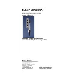
<strong>StreamPro</strong> <strong>ADCP</strong> <strong>Operation</strong> <strong>Manual</strong>2.3 <strong>StreamPro</strong> OverviewThe transducer assembly contains the transducer ceramics and the electronics.See “Specifications,” page 90 for dimensions and weights.Float and Boom – The float and deployment boom are designed to maintainthe transducer at a constant depth in the water with minimal water flow disturbance.Electronics Housing – The blue and white plastic housing protects the electronicsand is “splash proof” (i.e. it can be submerged in depths to one totwo meters for short periods of time as you retrieve the <strong>StreamPro</strong>).Transducer– The transducer ceramics are mounted to the transducer. Thethermistor is embedded in the transducer head and measures the water temperature.Power Switch and LEDs – The power switch is located on the electronicshousing. The amber LED on the electronics housing indicates power on;the blue LED indicates that a Bluetooth link has been acquired. A blinkingamber LED indicates the battery level is low.ELECTRONICS HOUSINGBOOMFLOATTRANSDUCERFigure 1.<strong>StreamPro</strong> Overviewpage 6Teledyne RD Instruments
<strong>StreamPro</strong> <strong>ADCP</strong> <strong>Operation</strong> <strong>Manual</strong>3 <strong>StreamPro</strong> CareThis section contains a list of items you should be aware of every time youhandle, use, or deploy your <strong>StreamPro</strong>. Please refer to this list often.NOTE. TDRI’s SmartLink has very useful information including links to thedocumentation, software, and firmware. It is good to check it periodicallyfor updated information. http://rdinstruments.com/smartlink/sp/3.1 General Handling Guidelines• Never set the transducer on a hard or rough surface. The urethanefaces may be damaged.• Do not expose the transducer faces to prolonged sunlight. Theurethane faces may develop cracks. Cover the transducerfaces on the <strong>StreamPro</strong> if it will be exposed to sunlight.• Do not store the <strong>StreamPro</strong> <strong>ADCP</strong> in extreme temperatures (seeTable 27, page 95). The urethane faces may be damaged.• Do not lift or support a <strong>StreamPro</strong> by the external cable. Theconnector or cable will break.• Do not leave the batteries inside the <strong>StreamPro</strong> <strong>ADCP</strong> for extendedperiods. The batteries may leak, causing damage tothe electronics. Store the batteries in a cool, dry location (0 to21 degrees C).3.2 Assembly Guidelines• Read the Maintenance section for details on <strong>StreamPro</strong> assembly.Loose, missing, stripped hardware, or damaged O-rings canlead to water ingress and damage to the <strong>StreamPro</strong> <strong>ADCP</strong>.• Do not connect or disconnect the transducer cable with powerapplied. When you connect the cable with power applied, youmay see a small spark. The connector pins may become pittedand worn.3.3 Deployment Guidelines• Read the <strong>StreamPro</strong> Quick Start Guide. This guide will helpyou learn how to use the <strong>StreamPro</strong>.• Bluetooth communications will not work if the internal temperatureof the <strong>StreamPro</strong> <strong>ADCP</strong> is above 50 degrees C. Ifyou are having communication problems and are operating in ahot, sunny climate, allow the <strong>StreamPro</strong> <strong>ADCP</strong> to cool beforecontinuing.P/N 95B-6003-00 (February 2008) page 7
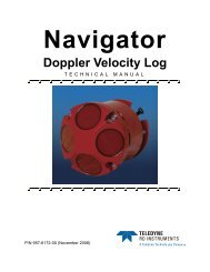
<strong>StreamPro</strong> <strong>ADCP</strong> <strong>Operation</strong> <strong>Manual</strong>4 <strong>StreamPro</strong> AssemblyThis section shows how to assemble the <strong>StreamPro</strong> float and attach thetransducer to the deployment boom.Solar ShieldElectronicsHousingTowing HarnessMounting PlatesTransducerFloatBoomFigure 2.<strong>StreamPro</strong> Assembly – Boom in Extended PositionSolar ShieldTowingHarnessTransducerElectronicsHousingCounterweightBoomMounting PlatesFloatFigure 3.<strong>StreamPro</strong> Assembly – Boom in in-hull Positionpage 8Teledyne RD Instruments
<strong>StreamPro</strong> <strong>ADCP</strong> <strong>Operation</strong> <strong>Manual</strong>Mounting LinePush down until alignedwith top of boom.Figure 4.Transducer Adjustment for In-Hullc. Tighten the thumbscrew on the clamp to hold the transducer in place.Adjust Towing Harness AngleAttach the towing harness to the float using the four provided screws, splitwashers, and flat washers. Adjust the angle of the towing harness as neededby pulling both pins and lifting the arm. Make sure both pins are engagedand equally positioned.NOTE. The towing harness may be pre-installed.page 10Teledyne RD Instruments
<strong>StreamPro</strong> <strong>ADCP</strong> <strong>Operation</strong> <strong>Manual</strong>5 <strong>StreamPro</strong> Communications SetupThis section shows how to setup the communications between the Stream-Pro <strong>ADCP</strong> and the iPAQ Pocket PC running the <strong>StreamPro</strong> software.NOTE. If the <strong>StreamPro</strong> program is running and connected to the<strong>StreamPro</strong> <strong>ADCP</strong>, first exit <strong>StreamPro</strong> and then turn off power to the<strong>StreamPro</strong> <strong>ADCP</strong> to release the COM Port.CAUTION. Always exit <strong>StreamPro</strong> before shutting power off to the<strong>StreamPro</strong> <strong>ADCP</strong>. If the Bluetooth serial COM port is open when the<strong>StreamPro</strong> <strong>ADCP</strong> is powered off, then the iPAQ Pocket PC will not powerback on correctly. Use a soft reset to restore the iPAQ Pocket PC.5.1 Creating a Bluetooth ShortcutBefore you can make a Bluetooth connection, you must create a shortcut tothe <strong>StreamPro</strong> <strong>ADCP</strong>.NOTE. You will use this shortcut (see Figure 5, page 12) each time youconnect to the <strong>StreamPro</strong> <strong>ADCP</strong>.a. Turn on power to the <strong>StreamPro</strong> <strong>ADCP</strong>.b. Start Bluetooth. The blue LED on the iPAQ Pocket PC should light.Start the Bluetooth Manager.c. On the Bluetooth Manager menu in the lower left corner, tap New, andthen Connect.d. Select Explore a Bluetooth device, and then tap Next.e. Tap the No device Selected box. The iPAQ Pocket PC will search forBluetooth devices.f. Select the RDI SPro icon and then tap Next.g. Tap Serial Port, and then tap Next.h. Tap Finish.P/N 95B-6003-00 (February 2008) page 11
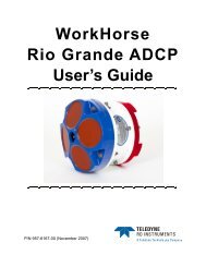
<strong>StreamPro</strong> <strong>ADCP</strong> <strong>Operation</strong> <strong>Manual</strong>Figure 5.Bluetooth Shortcut to the <strong>StreamPro</strong> <strong>ADCP</strong>5.2 Establish a Bluetooth ConnectionThe <strong>StreamPro</strong> <strong>ADCP</strong> communicates with the iPAQ Pocket PC using Bluetoothprotocols. To establish a Bluetooth connection, do the following.a. Turn on power to the <strong>StreamPro</strong> <strong>ADCP</strong>. The Amber LED indicatespower is on. If the amber LED light is blinking, replace the <strong>StreamPro</strong><strong>ADCP</strong> batteries.b. Turn on Bluetooth.c. Start the Bluetooth Manager.d. Tap and hold the <strong>StreamPro</strong> icon, then tap Connect.e. The Bluetooth connection will take several seconds to connect. Observethat the Bluetooth light on the <strong>StreamPro</strong> <strong>ADCP</strong> is ON/Solid.NOTE. If you have a problem connecting, check the battery levels are OKfor both the iPAQ Pocket PC and the <strong>StreamPro</strong> <strong>ADCP</strong>.Using Bluetooth increases battery usage for the iPAQ Pocket PC. TurnBluetooth off when not using to conserve the battery.Test the Bluetooth ConnectionOnce you have established a connection to the <strong>StreamPro</strong> <strong>ADCP</strong>, you cantest the Bluetooth connection.a. Start <strong>StreamPro</strong> and tap the Setup tab. Tap Configuration File. SelectFactory Default to set the <strong>StreamPro</strong> to the default settings.b. Tap the Test tab.c. Tap Instrument and tap Start Pinging.page 12Teledyne RD Instruments
<strong>StreamPro</strong> <strong>ADCP</strong> <strong>Operation</strong> <strong>Manual</strong>NOTE. Pinging in air will display the Number Good Bins as 0 andVelocity as BAD. This is normal and will not harm the <strong>StreamPro</strong> <strong>ADCP</strong>.d. Press the iTask button (the lower left button) on the iPAQ Pocket PC toreturn to the Bluetooth Manager.e. Tap and hold the <strong>StreamPro</strong> icon, then tap Status. You should seebytes Sent and Received on the Activity section.f. Tap OK.g. Press the iTask button (lower left button) to return to the <strong>StreamPro</strong>program and use the Test tab to stop pinging.Figure 6.Testing the Bluetooth ConnectionP/N 95B-6003-00 (February 2008) page 13
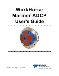
<strong>StreamPro</strong> <strong>ADCP</strong> <strong>Operation</strong> <strong>Manual</strong>6 Testing Your <strong>StreamPro</strong> <strong>ADCP</strong>Use the following steps to test the <strong>StreamPro</strong>.a. Turn on the power switch on the <strong>StreamPro</strong> <strong>ADCP</strong>.b. Establish a Bluetooth connection (see “Establish a Bluetooth Connection,”page 12).c. Start <strong>StreamPro</strong> on the iPAQ Pocket PC.d. Load the factory default configuration file by doing the following.1. Tap the Setup tab.2. Tap Configuration File.3. Select Factory Default to set the <strong>StreamPro</strong> to the default settings.You should see the message “Factory Defaults Loaded.”e. Tap the Test tab.f. Tap Instrument.g. Tap Self-Test. Once the test is complete, use the scroll bar on the rightside of the screen to view all the test results (see Figure 7).Figure 7.Testing the <strong>StreamPro</strong>NOTE. If any test fails, contact Teledyne RD Instruments.page 14Teledyne RD Instruments
<strong>StreamPro</strong> <strong>ADCP</strong> <strong>Operation</strong> <strong>Manual</strong>7 TroubleshootingIf you have problems establishing a Bluetooth communication link, checkthe following items and use Table 3, page 16.a. Does the <strong>StreamPro</strong> have power ON? Is the amber LED on? A blinkingamber LED indicates the battery level is low. Replace the AA batterieswith eight fresh batteries and try again to establish a Bluetooth communicationlink.b. Is the blue LED on the iPAQ Pocket PC lit? If not, charge the iPAQPocket PC battery.NOTE. If the iPAQ Pocket PC battery voltage is too low, Bluetooth will notturn on. Charge the battery before continuing.c. If the Bluetooth serial COM port is open when the <strong>StreamPro</strong> <strong>ADCP</strong> ispowered off, then the iPAQ Pocket PC will not power back on correctly.Use a soft reset to restore the iPAQ Pocket PC.NOTE. Always exit <strong>StreamPro</strong> and turn Bluetooth off before shuttingpower off to the <strong>StreamPro</strong> <strong>ADCP</strong>.d. Is the iPAQ Pocket PC within 10 meters of the <strong>StreamPro</strong>?e. Test the Bluetooth connection (see “Establish a Bluetooth Connection,”page 12).CAUTION. Bluetooth communications will not work if the internaltemperature of the <strong>StreamPro</strong> <strong>ADCP</strong> is above 50 degrees C. If you arehaving communication problems and are operating in a hot, sunny climate,allow the <strong>StreamPro</strong> <strong>ADCP</strong> to cool before continuing.NOTE. Storing the <strong>StreamPro</strong> <strong>ADCP</strong> in the trunk of a car on a sunny daycan cause the internal temperature of the <strong>StreamPro</strong> <strong>ADCP</strong> to exceed 50degrees C.P/N 95B-6003-00 (February 2008) page 15
<strong>StreamPro</strong> <strong>ADCP</strong> <strong>Operation</strong> <strong>Manual</strong>Table 3:Problem / IndicationAmber LED on the <strong>StreamPro</strong><strong>ADCP</strong> does not lightAmber LED on the <strong>StreamPro</strong><strong>ADCP</strong> is blinkingTroubleshooting the <strong>StreamPro</strong> <strong>ADCP</strong>Blue LED on the <strong>StreamPro</strong> <strong>ADCP</strong>does not lightBlue LED on iPAQ Pocket PC doesnot lightNo Bluetooth/Wireless icon visibleon Today screeniPAQ Pocket iPAQ Pocket PC willnot turn oniPAQ Pocket PC charge light will notlight when placed in the chargerBluetooth connection is intermittentPossible SolutionReplace the <strong>StreamPro</strong> <strong>ADCP</strong> AA batteries.The battery level is getting low. Replace the<strong>StreamPro</strong> <strong>ADCP</strong> AA batteries.COM port is locked. Do a shutdown and coldstart (see Quick Start Guide).Replace <strong>StreamPro</strong> <strong>ADCP</strong> AA batteriesCharge the iPAQ Pocket PC battery<strong>StreamPro</strong> <strong>ADCP</strong> internal temperature maybe above 50° C. Move the <strong>StreamPro</strong> <strong>ADCP</strong>to a cooler location and attempt to communicateagain.Charge iPAQ Pocket PC batteryDo a soft reset on the iPAQ Pocket PCCharge iPAQ Pocket PC battery for at leastone hour. You may need to do a soft reset torestore normal operation.The battery may have totally discharged.Place the iPAQ Pocket PC in the charger forat least one hour. You may need to do a softreset after the first hour of charging to fullycharge the battery.Out of range – The iPAQ Pocket PC must bewithin 10 meters of the <strong>StreamPro</strong> <strong>ADCP</strong>.<strong>StreamPro</strong> <strong>ADCP</strong> internal temperature maybe above 50° C. Move the <strong>StreamPro</strong> <strong>ADCP</strong>to a cooler location and attempt to communicateagain.Replace the <strong>StreamPro</strong> <strong>ADCP</strong> AA batteriesCharge the iPAQ Pocket PC batteryCAUTION. The serial port is always open while <strong>StreamPro</strong> is running.Always exit <strong>StreamPro</strong> and turn Bluetooth off before shutting power off tothe <strong>StreamPro</strong> <strong>ADCP</strong> or removing the SD storage card.Performing a shutdown and cold start will release the COM Port.In rare cases it may be necessary to perform a hard reset. See the<strong>StreamPro</strong> Software User’s Guide for details on how to do a hard reset.page 16Teledyne RD Instruments
<strong>StreamPro</strong> <strong>ADCP</strong> <strong>Operation</strong> <strong>Manual</strong>8 <strong>StreamPro</strong> MaintenanceThis section explains how to prepare the <strong>StreamPro</strong> for deployment, how todo certain maintenance, and how to prepare the <strong>StreamPro</strong> for storage orshipment.8.1 Spare PartsThe following parts are included in the spare parts kit.Table 4:DescriptionSpare PartsPart numberO-ring, housing cover 2-162O-ring, battery cover 2-036Desiccant, sealed bagLubricant, silicone, 5.3 oz, Dow-CorningHolder, batteryScrew, thumb, 6-32x5/8, SSScrew, thumb, M40x0.7x14.5MM, SSWasher, wavy, .24ID x .31 OD x0.3THK, 302 SSWasher, 6mm Split Lock, SS316Washer, Flat, 12.5MMOD, SST 316Screw, SHCS, 316Screw, SKT HD, SST 316DES3DC-111BH48AASF91035A40095536A3319714K23M6WASHSPLM6WASHSTDM6X1.0X20SHCSM6x1.0x30SHP/N 95B-6003-00 (February 2008) page 17
<strong>StreamPro</strong> <strong>ADCP</strong> <strong>Operation</strong> <strong>Manual</strong>M6 BOLTLOCK WASHERTHUMB SCREWSFLAT WASHERHOUSING COVERCOVER PLATEO-RINGBATTERYCOVERBATTERYCOVERO-RINGBATTERYPACKPROTECTIVECAPPOWER SWITCHand LEDsFigure 8.<strong>StreamPro</strong> Electronic Housing Assemblypage 18Teledyne RD Instruments
<strong>StreamPro</strong> <strong>ADCP</strong> <strong>Operation</strong> <strong>Manual</strong>8.2 Transducer AssemblyThe cable on the <strong>StreamPro</strong> transducer housing is a molded connector. Donot attempt to remove the cable from the transducer. The cable connectoron the electronic housing is a factory-installed item. We do not recommendremoving it for any routine maintenance.To make the connection, remove the protective cap from the receptacle onthe electronics housing. Insert the cable connector into the receptacle, rotatingit until the keyed portions are properly aligned. Thread the couplingring onto the receptacle to complete the connection.NOTE. The protective cap should be installed on the connector any timethe cable is removed from the electronic housing. Use the cap when the<strong>StreamPro</strong> is in storage or is being handled.Figure 9.<strong>StreamPro</strong> Transducer AssemblyNOTE. The Transducer assembly is a molded one-piece unit. Do notattempt to dissemble.Figure 10.Transducer Cable ConnectorNOTE. The cable connector is keyed to ensure proper connection.P/N 95B-6003-00 (February 2008) page 19
<strong>StreamPro</strong> <strong>ADCP</strong> <strong>Operation</strong> <strong>Manual</strong>8.3 Solar Shield RemovalRemove the solar shield by loosening the attached thumbscrews connectedto the M6 standoff bolts on the electric housing cover plate.CAUTION. Removing the sunshield can possibly lead to the four M6standoff bolts on the top of the electronic housing to become loose, andtherefore compromising the water seal integrity. Always check that theM6 standoff bolts that the solar shield attaches to are secure (seeFigure 11).If one or more of the M6 standoff bolts are loose, remove the cover plateand check the O-ring condition (see “Electronic Housing Cover PlateRemoval,” page 22).NOTE. Only loosen the thumbscrews enough to remove the solar shield –do not remove the thumbscrews from the shield.Spring washer under compressionSpring washer not compressedFigure 11.M6 Standoff Bolt on Electronic Housing Cover Plate8.4 Battery ReplacementThe <strong>StreamPro</strong> requires 12 VDC nominal. Use eight AA Alkaline batteriesor eight AA Rechargeable Nickel-metal hydride batteries. For the longestcontinuous operation time, use eight AA Lithium batteries (see Table 25,page 91).CAUTION.Ensure that proper polarity is observed when installing batteriesDo not mix old and new batteriesDo not mix alkaline with non-alkaline batteriesDo not use damaged batteriesDo not mix batteries of different brandsDo not use expired batteries (See battery exp. Date)Do not leave the batteries inside the <strong>StreamPro</strong> <strong>ADCP</strong> for extended periods.The batteries may leak, causing damage to the electronics.Store the batteries in a cool, dry location (0 to 21 degrees C).page 20Teledyne RD Instruments
<strong>StreamPro</strong> <strong>ADCP</strong> <strong>Operation</strong> <strong>Manual</strong>NOTE. When using eight AA cells, check that the battery voltage is above11.5 Volts DC. <strong>StreamPro</strong> <strong>ADCP</strong>s will work at 11.5 volts; however,batteries with voltages below 11.5 volts are at or near their end of life andare approaching uselessness.A blinking amber LED indicates the battery level is low.Replace the batteries by doing the following.a. Turn the power switch OFF.b. Remove the solar shield by loosing the four thumbscrews.c. Open the battery compartment door by loosening the three thumbscrews.NOTE. Only loosen the thumbscrews enough to remove the cover – donot remove the thumbscrews from the battery cover.d. Remove the battery holder.e. Remove all of the old batteries.f. Replace with eight new Alkaline AA batteries. Match the battery polarityas shown on the battery holder.g. Observe that the inside of the battery housing area is dry and clean.Thoroughly clean both the cover plate and the blue surface area aroundthe O-ring.h. Place the battery holder in the housing making sure the battery contactson the holder match the two springs inside the housing (see Figure 12,page 22).i. The battery compartment O-ring is normally held in place because thegroove it sits in is dovetailed. Should the O-ring ever fall out or it appearsdry or hard, replace it and apply the smallest amount possible ofthe silicone lubricant included in the tool kit. Beware too much lubricantattracts dirt; therefore apply it exceedingly sparingly. Use a lintfree cloth to remove any excess lubricant (see “Battery Compartment O-Ring Inspection & Replacement,” page 24).j. Close the battery compartment door and tighten the thumbscrews. Asyou tighten all three thumbscrews, tilt the housing to see that the O-ringhas not moved out of the O-ring slot (see Figure 13, page 22). Tightenall three thumbscrews in rotation a couple turns at a time so that thecover comes down evenly and squarely on the housing. Only tighten thebattery cover thumbscrews finger tight.CAUTION. Although each thumbscrew has a screwdriver slot, do NOTuse any tools to tighten the screws. Over-tightening can cause thethreads to strip.P/N 95B-6003-00 (February 2008) page 21
<strong>StreamPro</strong> <strong>ADCP</strong> <strong>Operation</strong> <strong>Manual</strong>k. Replace the solar shield (see “Solar Shield Replacement,” page 26).Figure 12.<strong>StreamPro</strong> Battery ReplacementBattery Cover PlateClean both surfaces!Figure 13.Check O-RingPlacementClosing the Battery Cover8.5 Electronic Housing Cover Plate RemovalNOTE. Normal maintenance does not require dissembling the <strong>StreamPro</strong><strong>ADCP</strong> electronic housing. Only use the following procedures if directed todo so by TRDI Field Service personnel.a. Turn the power switch OFF.b. Remove the transducer cable and place the cap on the cable connector(see “Transducer Assembly,” page 19).c. Remove the solar shield by loosing the four thumbscrews.page 22Teledyne RD Instruments
<strong>StreamPro</strong> <strong>ADCP</strong> <strong>Operation</strong> <strong>Manual</strong>d. Open the battery compartment door and remove the battery pack (see“Battery Replacement,” page 20).e. Loosen (do not remove) the four standoff bolts (M6) to vent the system.f. Once all four bolts have been loosened, remove the four bolts that attachthe housing cover to the housing assembly. Check inside the housingfor any discoloration or water damage. If in doubt, contact Teledyne RDInstruments.g. Clean the O-ring mating surfaces with a soft, lint-free cloth. Inspect thesurfaces for damage (see “Cover Plate O-Ring Inspection and Replacement,”page 23).h. When you are ready to re-assemble the <strong>StreamPro</strong>, see “<strong>StreamPro</strong> Reassembly,”page 23.8.6 <strong>StreamPro</strong> Re-assemblyTo replace the housing cover plate, proceed as follows.8.6.1 Cover Plate O-Ring Inspection and ReplacementThis section explains how to inspect/replace the <strong>StreamPro</strong> O-ring. A successfuldeployment depends on the condition of O-ring and the retaininggroove. Read all instructions before doing the required actions.We strongly recommend cleaning the O-ring whenever you disassemble the<strong>StreamPro</strong>. Inspecting and cleaning the O-ring should be the last maintenancetask done before sealing the <strong>StreamPro</strong>.a. Inspect the O-ring. When viewed with an unaided eye, the O-ring mustbe free of cuts, indentations, abrasions, foreign matter, and flow marks.The O-ring must be smooth and uniform in appearance. Defects mustbe less then 0.1 mm (0.004 in.).CAUTION. If the O-ring appears compressed from prior use, replace it.Weak or damaged O-rings will cause the <strong>StreamPro</strong> to flood.b. Clean and inspect the O-ring groove. Be sure the groove is free of foreignmatter, scratches, indentations, corrosion, and pitting. Run yourfingernail across damaged areas. If you cannot feel the defect, the damagemay be minor; otherwise, the damage may need repair.CAUTION. Check the O-ring groove thoroughly. Any foreign matter inthe O-ring groove will cause the <strong>StreamPro</strong> to flood.c. If a scratch is on the plastic housing flange O-ring groove, it may begently sanded using 600-grit (wet) sandpaper. Use care not to cause furtherdamage.P/N 95B-6003-00 (February 2008) page 23
<strong>StreamPro</strong> <strong>ADCP</strong> <strong>Operation</strong> <strong>Manual</strong>d. Lubricate the O-ring with a thin coat of silicone lubricant. Apply thelubricant using latex gloves. Do not let loose fibers or lint stick to theO-ring. Fibers can provide a leakage path.NOTE. TRDI uses Dow Corning’s silicone lube model number 111 but anytype of silicone O-ring lube can be used.CAUTION. Apply a very thin coat of silicone lube on the O-ring. Usingtoo much silicone lube on the O-ring can be more harmful than using noO-ring lube at all.8.6.2 Battery Compartment O-Ring Inspection & ReplacementThe battery compartment O-ring is normally held in place because thegroove it sits in is dovetailed. Should the O-ring ever fall out or it appearsdry or hard, replace it. Replace the Battery Compartment O-Ring by doingthe following.a. Turn the power switch OFF.b. Remove the solar shield by loosing the four thumbscrews.c. Open the battery compartment door by loosening the thumbscrew.d. Inspect the O-ring. When viewed with an unaided eye, the O-ring mustbe free of cuts, indentations, abrasions, foreign matter, and flow marks.The O-ring must be smooth and uniform in appearance. Defects mustbe less then 0.1 mm (0.004 in.).CAUTION. If the O-ring appears compressed from prior use, replace it.Weak or damaged O-rings will cause the <strong>StreamPro</strong> to flood.e. Clean and inspect the O-ring groove and the surface around the O-ring.Be sure the groove is free of foreign matter, scratches, indentations, corrosion,and pitting. Run your fingernail across damaged areas. If youcannot feel the defect, the damage may be minor; otherwise, the damagemay need repair. Clean the battery cover plate with a lint free cloth.CAUTION. Check the O-ring groove thoroughly. Any foreign matter inthe O-ring groove will cause the <strong>StreamPro</strong> to flood.f. Lubricate the O-ring with a thin coat of silicone lubricant. Apply thelubricant using latex gloves. Do not let loose fibers or lint stick to theO-ring. Fibers can provide a leakage path.NOTE. TRDI uses Dow Corning’s silicone lube model number 111 but anytype of silicone O-ring lube can be used.page 24Teledyne RD Instruments
<strong>StreamPro</strong> <strong>ADCP</strong> <strong>Operation</strong> <strong>Manual</strong>CAUTION. Be aware that too much lubricant attracts dirt; therefore apply itexceedingly sparingly. Use a lint free cloth to remove any excesslubricant.g. Check that the battery compartment O-ring is in the O-ring groove (seeFigure 13, page 22).h. Close the battery compartment door and tighten the thumbscrew. Onlytighten the battery cover thumbscrews finger tight.CAUTION. Although each thumbscrew has a screwdriver slot, do NOTuse any tools to tighten the screws. Over-tightening can cause thethreads to strip.8.6.3 Electronic Housing Cover Plate ReplacementWhen replacing the cover plate, observe that the inside of the housing areais dry and clean. There should be no signs of water ingress, discoloration,or dampness. If in doubt, contact Teledyne RD Instruments.a. Make sure all printed circuit boards, spacers, cables, and screws havebeen installed.b. Inspect, clean, and lubricate the O-ring on the housing (see “Cover PlateO-Ring Inspection and Replacement,” page 23).CAUTION. Follow all the steps for O-Ring Inspection and Replacement(see “Cover Plate O-Ring Inspection and Replacement,” page 23). Thewatertight integrity of the <strong>StreamPro</strong> depends on this seal.c. Install two fresh bags of desiccant just before closing the <strong>StreamPro</strong> (see“Desiccant Bags,” page 26).d. Gently place the cover onto the housing assembly, aligning the matingholes. When mating the cover with the housing flange try to apply equalpressure to all parts of the O-ring. Make sure the O-ring remains in theretaining groove.CAUTION. Check that no wires or any other object is pinched between thecover and the housing. If the O-ring is not in the groove or if a wire orother object is pinched, the <strong>StreamPro</strong> will flood.e. Examine the housing assembly standoff bolts, split washer, and flatwashers (M6) for corrosion: replace if necessary. All hardware itemsare needed to seal the <strong>StreamPro</strong> properly.f. Place one drop of Loctite 425 on the M6 standoff bolts duringreassembly.g. Install all four sets of hardware until “finger tight.”P/N 95B-6003-00 (February 2008) page 25
<strong>StreamPro</strong> <strong>ADCP</strong> <strong>Operation</strong> <strong>Manual</strong>h. Tighten the standoff bolts in small increments in a “cross” pattern untilthere is no gap between the cover plate and housing, and then tighteneach standoff bolt ¼ turn more to compress the face seal O-ring evenly.Tighten the M6 standoff bolts to 10 inch/pounds (1.13 nm).CAUTION. Apply equal pressure to the O-ring as you tighten the bolts. Ifone bolt is tightened more then the others, the O-ring can become pinchedor torn. A damaged O-ring will cause the <strong>StreamPro</strong> to flood.CAUTION. Do not over tighten the bolts that hold the cover plate andhousing together. If you tighten too much, you can crack or deform theplastic cover. On the other hand, leaving the bolts too loose can cause thesystem to flood.Tighten the M6 standoff bolts to 10 inch/pounds (1.13 nm).i. Slide the battery pack into the compartment and check that the batterycompartment O-ring is in the retaining groove. Close and tighten thebattery compartment door.8.7 Solar Shield ReplacementAttach the solar shield to the standoff bolts on the electric housing coverplate using the attached thumbscrews. Tighten the thumbscrews “fingertight”. Do not over tighten.CAUTION. It is important to only gently finger tighten the sunshieldscrews when placing the sunshield back on the electronic housing M6standoff bolts. Should any movement occur on the M6 standoff bolts dueto over tightening the sun shield screws, the Loctite seal will be broken,and thus allowing the M6 standoff bolts to subsequently become loose(see Figure 11, page 20).8.8 Desiccant BagsDesiccant bags are used to dehumidify the housing interior. Desiccant isessential in deployments with plastic housings. The factory-supplied desiccantlasts a year. Remember that desiccant rapidly absorbs moisture fromnormal room air if the housing is opened.The average dry weight of a new desiccant bag is 7.2 grams ((5%). Theweight increases to 8.4 to 9 grams for a “used” desiccant bag. Used desiccantbags may be dried at 250° for 14 hours. As a minimum, replace thedesiccant bags once per year or whenever you are preparing to store the<strong>StreamPro</strong> for an extended time.CAUTION. Do not open the desiccant bag. Contact with the silica gel cancause nose, throat, and skin irritation.page 26Teledyne RD Instruments
<strong>StreamPro</strong> <strong>ADCP</strong> <strong>Operation</strong> <strong>Manual</strong>NOTE. Desiccant bags are shipped in an airtight aluminum bag to ensuremaximum effectiveness. There is a moisture indicator inside the bag. Ifthe moisture indicator is pink, do not use the desiccant bag until it hasbeen dried. TRDI recommends replacing the desiccant bag once per year.a. Remove the housing cover plate (see “Electronic Housing Cover PlateRemoval,” page 22).b. Remove the new desiccant bags from the airtight aluminum bag.c. Remove the old desiccant bags and install two new ones. Place the desiccantbags between the top circuit board and the housing.d. Install the housing cover plate (see “Electronic Housing Cover Plate Replacement,”page 25).8.9 Storage and Shipping MaintenanceThis section lists the maintenance items to do before storing the <strong>StreamPro</strong>.These maintenance items include:• Removing biofouling (see “Removal of Biofouling,” page 27).• Inspecting the transducer head (see “Transducer Head Inspection,”page 28).• Preparing the <strong>StreamPro</strong> for final storage (see “Final Storage,”page 28)• Shipping Preparation (see “Shipping Preparation,” page 30)8.9.1 Removal of BiofoulingBefore storing or shipping the <strong>StreamPro</strong>, remove all foreign matter andbiofouling. Remove soft-bodied marine growth or foreign matter withsoapy water. Waterless hand cleaners remove most petroleum-based fouling.Rinse with fresh water to remove soap residue. Dry the transducerfaces with low-pressure compressed air or soft lint-free towels. Dry thefloat and electronics housing with towels.CAUTION. The soft, thin urethane coating on the transducer faces iseasily damaged. Do not use power scrubbers, abrasive cleansers,scouring pads, high-pressure marine cleaning systems, or brushes stifferthan hand cleaning brushes on the transducer faces.CAUTION. Always dry the <strong>StreamPro</strong> before placing it in the storage caseto avoid fungus or mold growth. Do not store the <strong>StreamPro</strong> <strong>ADCP</strong> in wetor damp locations.P/N 95B-6003-00 (February 2008) page 27
<strong>StreamPro</strong> <strong>ADCP</strong> <strong>Operation</strong> <strong>Manual</strong>8.9.2 Transducer Head InspectionThe urethane coating on the transducer faces is important to <strong>StreamPro</strong> watertightintegrity. Mishandling, chemicals, abrasive cleaners, and excessivedepth pressures can damage the transducer ceramics or urethane coating.Inspect the transducer faces for dents, chipping, peeling, urethane shrinkage,hairline cracks, and damage that may affect watertight integrity ortransducer operation. Repair of the transducer faces should only be done byTRDI.CAUTION. Never set the transducer on a rough surface; always use foampadding to protect the transducer.NOTE. The cap should be installed any time the transducer cable isremoved. Use the cap when the <strong>StreamPro</strong> is in storage or is beinghandled.8.9.3 Final StorageStore the <strong>StreamPro</strong> in the original shipping crate whenever possible.a. Remove the batteries from the battery holder.b. Remove the transducer from the boom arm and disconnect the transducercable. Place the protective cap on the electronic housing transducercable connector.c. Dissemble the boom arm from the float.d. Place the transducer and boom arm in the foam cutouts in the bottom ofthe shipping case.e. The electronic housing/float assembly fits in the case with the electronichousing held in place by the cutout in the foam. Use the other cutout tostore the iPAQ Pocket PC, manuals, and spare parts.page 28Teledyne RD Instruments
<strong>StreamPro</strong> <strong>ADCP</strong> <strong>Operation</strong> <strong>Manual</strong>Figure 14.<strong>StreamPro</strong> Shipping CaseCAUTION. Always dry the <strong>StreamPro</strong> before placing it in the storage caseto avoid fungus or mold growth. Do not store the <strong>StreamPro</strong> <strong>ADCP</strong> in wetor damp locations.NOTE. The protective cap should be installed any time the transducercable is removed. Use the cap when the <strong>StreamPro</strong> is in storage or isbeing handled.CAUTION. Do not leave the batteries inside the <strong>StreamPro</strong> <strong>ADCP</strong> forextended periods. The batteries may leak, causing damage to theelectronics. Store the batteries in a cool, dry location (0 to 21 degrees C).P/N 95B-6003-00 (February 2008) page 29
<strong>StreamPro</strong> <strong>ADCP</strong> <strong>Operation</strong> <strong>Manual</strong>8.9.4 Shipping PreparationThis section explains how to ship the <strong>StreamPro</strong>.CAUTION. If you are shipping a <strong>StreamPro</strong> to TRDI for repair or upgrade,remove all customer-applied coatings or provide certification that thecoating is nontoxic. This certification must include the name of a contactperson who is knowledgeable about the coating, the name, andmanufacturer of the coating, and the appropriate telephone numbers. Ifyou return the equipment without meeting these conditions, we haveinstructed our employees not to handle the equipment and to leave it in theoriginal shipping container pending certification. If you cannot providecertification, we will return the equipment to you or to a customer-specifiedcleaning facility. All costs associated with customer-applied coatings willbe at the customer's expense.When shipping the <strong>StreamPro</strong> through a Customs facility, be sure to placethe unit/s so identifying labels are not covered and can be seen easily by theCustoms Inspector. Failure to do so could delay transit time.NOTE. TRDI strongly recommends using the original shipping cratewhenever transporting the <strong>StreamPro</strong>.If you need to ship or store the <strong>StreamPro</strong>, use the original shipping cratewhenever possible. If the original packaging material is unavailable or unserviceable,additional material is available through TRDI.For repackaging with commercially available materials, use the followingprocedure:a. Remove the transducer assembly from the boom arm.b. Remove the electronic housing from the float.c. Use a strong shipping container made out of wood or plastic.d. Install a layer of shock-absorbing static-shielding material, 70-mm to100-mm thick, around all sides of the instrument to firmly cushion andprevent movement inside the container.e. Seal the shipping container securely.f. Mark the container FRAGILE to ensure careful handing.g. In any correspondence, refer to the <strong>StreamPro</strong> by model and serialnumber.page 30Teledyne RD Instruments
<strong>StreamPro</strong> <strong>ADCP</strong> <strong>Operation</strong> <strong>Manual</strong>8.10 Returning <strong>StreamPro</strong> <strong>ADCP</strong>s to TRDI for ServiceWhen shipping the <strong>StreamPro</strong> to TRDI from either inside or outside theUnited States, the following instructions will help ensure the <strong>StreamPro</strong> arriveswith the minimum possible delay. Any deviation from these instructionsincreases the potential for delay.8.10.1 Domestic ShipmentsStep 1 - Get a Return Material AuthorizationSend an e-mail to TRDI’s Sales Administration (rdicsadmin@teledyne.com) orcall Customer Service and request a Return Material Authorization (RMA)number. When requesting a RMA number, please give us the following information.• What is being shipped (include the serial number)• When you plan to send the shipment• What issue(s) need to be corrected• Name of the Field Service Engineer that knows about the issue• When you need the instrument returnedTRDI’s Customer Service will then respond with the RMA number for theshipment. Please include this number on all packages and correspondence.Step 2 – Provide a MSDS as necessaryPlease provide a Material Safety Data Sheet (MSDS) if the system/transduceris painted with antifouling paint.Step 3 - Ship via air freight, prepaidUrgent Shipments should be shipped direct to TRDI via overnight or priorityair services. Do not send urgent airfreight as part of a consolidatedshipment. If you ship consolidated, it will cost less, but may lose up tothree days in transit time.Non-urgent shipments may be shipped as part of a consolidated cargo shipmentto save money. In addition, some truck lines may offer equivalent deliveryservice at a lower cost, depending on the distance to San Diego.Mark the Package(s)To: Teledyne RD Instruments, Inc. (RMA Number)14020 Stowe DrivePoway, California 92064Airport of Destination = San DiegoNotify Paxton, Shreve, and Hayes, San Diego AirportPhone: +1 (619) 232-8941Fax: +1 (619) 232-8976P/N 95B-6003-00 (February 2008) page 31
<strong>StreamPro</strong> <strong>ADCP</strong> <strong>Operation</strong> <strong>Manual</strong>Step 4 - Urgent shipmentsSend the following information by fax or telephone to TRDI.Attention: Customer Service AdministrationFax: +1 (858) 842-2822Phone: +1 (858) 842-2600• Detailed descriptions of what you are shipping (number of packages,sizes, weights, and contents).• The name of the freight carrier• Master Air bill number• Carrier route and flight numbers for all flights the package willtake8.10.2 International ShipmentsStep 1 - Get a Return Material AuthorizationSend an e-mail to TRDI’s Sales Administration (rdiefs@teledyne.com) or callCustomer Service and request a Return Material Authorization (RMA)number. When requesting a RMA number, please give us the following information.• What is being shipped (include the serial number)• When you plan to send the shipment• What issue(s) need to be corrected• Name of the Field Service Engineer that knows about the issue• When you need the instrument returnedTRDI’s Customer Service will then respond with the RMA number for theshipment. Please include this number on all packages and correspondence.Step 2 – Provide a MSDS as necessaryPlease provide a Material Safety Data Sheet (MSDS) if the system/transduceris painted with antifouling paint.Step 3 - Ship Via Air Freight, PrepaidUrgent Shipments should be shipped direct to TRDI via overnight or priorityair services. Do not send urgent airfreight as part of a consolidatedshipment. If you ship consolidated, it will cost less, but may lose up tothree days in transit time.Non-urgent shipments may be shipped as part of a consolidated cargo shipmentto save money.page 32Teledyne RD Instruments
<strong>StreamPro</strong> <strong>ADCP</strong> <strong>Operation</strong> <strong>Manual</strong>Mark the package(s) as follows:To: Teledyne RD Instruments, Inc. (RMA Number)2A Les Nertieres5 Avenue Hector Pintus06610 La Gaude, FranceStep 4 - Include Proper Customs DocumentationThe Customs statement must be completed. It should be accurate and truthfullycontain the following information.• Contents of the shipment• Value• Purpose of shipment (example: “American made goods returnedfor repair”)• Any discrepancy or inaccuracy in the Customs statement couldcause the shipment to be delayed in Customs.Step 4 - Send the Following Information by Fax or Telephone to TRDIAttention: Sales AdministrationPhone: +33(0) 492-110-930Fax: +33(0) 492-110-931• Detailed descriptions of what you are shipping (number of packages,sizes, weights, and contents).• The name of the freight carrier• Master Air bill number• Carrier route and flight numbers for all flights the package willtakeP/N 95B-6003-00 (February 2008) page 33
<strong>StreamPro</strong> <strong>ADCP</strong> <strong>Operation</strong> <strong>Manual</strong>9 <strong>StreamPro</strong> CommandsThis section defines the commands used by the <strong>StreamPro</strong> <strong>ADCP</strong>s. Thesecommands let you set up and control the <strong>StreamPro</strong>. The commands directlyaffect the range of the <strong>StreamPro</strong> and the standard deviation (accuracy)of the data. Most <strong>StreamPro</strong> settings use factory-set values. If youchange these values without thought, you could ruin your deployment. Besure you know what effect each command has before using it. Call TRDI ifyou do not understand the function of any command.9.1 Data Communication and Command FormatYou can enter commands with an IBM-compatible computer with a Bluetoothinterface running TRDI’s BBTalk. The <strong>StreamPro</strong> communicates withthe computer through the Bluetooth interface.Immediately after you apply power to the <strong>StreamPro</strong>, it enters the standbymode. Send a = = = signal using BBTalk. When the <strong>StreamPro</strong> receives a= = = signal, it responds with a wake-up message similar to the one shownbelow. The <strong>StreamPro</strong> is now ready to accept commands at the “>” prompt.<strong>StreamPro</strong> <strong>ADCP</strong>Teledyne RD Instruments (c) 2003All rights reserved.Firmware Version: xx.xx>9.1.1 Command Input ProcessingInput commands set <strong>StreamPro</strong> operating parameters, start data collection,run built-in tests (BIT), and asks for output data. All commands are ASCIIcharacter(s) and must end with a carriage return (CR). For example,>WP0001 [Your input]If the entered command is valid, the <strong>StreamPro</strong> executes the command. Ifthe command is one that does not provide output data, the <strong>StreamPro</strong> sendsa carriage return line feed and displays a new “>” prompt.Continuing the example,>WP00001 [Your original input]> [<strong>StreamPro</strong> response to a valid, no-output command]If you enter a valid command that produces output data, the <strong>StreamPro</strong> executesthe command, displays the output data, and then redisplays the “>”prompt. Some examples of commands that produce output data are ? (helpmenus), CS (start pinging), PS (system configuration data), and PA (run builtintests).If the command is not valid, the <strong>StreamPro</strong> responds with an error messagesimilar to the following.page 34Teledyne RD Instruments
<strong>StreamPro</strong> <strong>ADCP</strong> <strong>Operation</strong> <strong>Manual</strong>>WPA>WPA ERR 002: NUMBER EXPECTED[Your input][<strong>StreamPro</strong> response]>After correctly entering all the commands for your application, you wouldsend the CS-command to begin the data collection cycle.9.1.2 Data Output ProcessingAfter the <strong>StreamPro</strong> completes a data collection cycle, it sends a block ofdata called a data ensemble. A data ensemble consists of the data collectedand averaged during the ensemble interval. A data ensemble can containheader, leader, velocity, correlation magnitude, echo intensity, and percentgood.<strong>StreamPro</strong> output data can be in either hexadecimal-ASCII (Hex-ASCII) orbinary format. The Hex-ASCII mode is useful when you use a terminal tocommunicate with, and view data from the <strong>StreamPro</strong>. The binary mode isuseful for high-speed communication with a computer program. You wouldnot use the binary mode to view data on a terminal because the terminalcould interpret some binary data as control codes.NOTE. All of Teledyne RD Instruments’ software supports binary PD0Output Data Format only.When data collection begins, the <strong>StreamPro</strong> uses the settings last entered(user settings) or the factory-default settings. The same settings are usedfor the entire deployment.The <strong>StreamPro</strong> automatically stores the last set of commands used in RAM.The <strong>StreamPro</strong> will continue to be configured from RAM until it receives aCR-command or until the RAM loses its backup power. If the <strong>StreamPro</strong>receives a CR0 it will load into RAM the command set you last stored innon-volatile memory (semi-permanent user settings) through the CKcommand.If the <strong>StreamPro</strong> receives a CR1, it will load into RAM the factorydefault command set stored in ROM (permanent or factory settings).P/N 95B-6003-00 (February 2008) page 35
<strong>StreamPro</strong> <strong>ADCP</strong> <strong>Operation</strong> <strong>Manual</strong>9.2 Firmware UpgradesWhen updating the firmware, the new firmware must be downloaded to the<strong>StreamPro</strong> <strong>ADCP</strong> using the program WinCEFlash.exe. To download newfirmware, do the following steps.a. Copy the <strong>StreamPro</strong> firmware from the Teledyne RD Instruments web<strong>site</strong> customer service page using the following link:http://www.rdinstruments.com/x/cs/software.html#spro. Place the zipfile on your computer’s hard drive and unzip the file. You should havethe following files.• WinCEFlash.exe• SPxx_xx.m0 (where xx_xx is the version number)• atlce400.dllb. Place the iPAQ Pocket PC in the cradle.c. When Microsoft ActiveSync starts, click the Explore icon.d. Double-click My Pocket PC. Use the File, New Folder menu to createa folder on the iPAQ Pocket PC where you plan to copy the firmwarefiles.e. Navigate to the folder where the firmware files are located on yourcomputer’s hard drive and select all three firmware files.f. On the Edit menu, select Copy To Folder and select the folder on theiPAQ where the firmware files will be copied.Figure 15.Create a New Folder on the iPAQNOTE. These firmware upgrade files can be copied to any folder on theiPAQ. Once the firmware has been updated you can delete these files ifspace is needed. All three files must be in the same folder.page 36Teledyne RD Instruments
<strong>StreamPro</strong> <strong>ADCP</strong> <strong>Operation</strong> <strong>Manual</strong>g. Before continuing, make sure the following conditions are met.• Disconnect the transducer cable from the electronics housing.• <strong>StreamPro</strong> program is not running on the iPAQ Pocket PC.• <strong>StreamPro</strong> <strong>ADCP</strong> has fresh batteries.• <strong>StreamPro</strong> <strong>ADCP</strong> power turned ON.• iPAQ Pocket PC has fully charged battery.• Turn the iPAQ Pocket PC Bluetooth ON.• Make sure the iPAQ and <strong>StreamPro</strong> <strong>ADCP</strong> are in close proximityto each other.CAUTION. If the transducer cable is not removed from the electronichousing before the firmware upgrade starts, the beam matrix in thetransducer will be overwritten. This will seriously degrade yourmeasurements. If this happens, please contact TRDI for information onhow to restore the beam matrix.If the <strong>StreamPro</strong> <strong>ADCP</strong> batteries go dead or communications between theiPAQ and <strong>StreamPro</strong> <strong>ADCP</strong> is lost during the firmware upgrade, thefirmware may be corrupted. If this happens, return the <strong>StreamPro</strong> <strong>ADCP</strong>to TRDI.h. On the iPAQ, tap File, Programs, File Explorer. Navigate to the folderwhere the firmware files were copied (see Figure 16).Figure 16.File ExplorerNOTE. By default, you will not see the atlce400.dll or the file extensions.P/N 95B-6003-00 (February 2008) page 37
<strong>StreamPro</strong> <strong>ADCP</strong> <strong>Operation</strong> <strong>Manual</strong>i. Tap the WinCEFlash file. Navigate to the folder where the *.m0 file islocated and tap to select the file (see Figure 17). Tap OK.Figure 17.WinCEFlash Programj. Wait for the Flash programming SUCESSFUL message (see Figure 18).Click OK to continue.Figure 18.WinCEFlash Done Messagepage 38Teledyne RD Instruments
<strong>StreamPro</strong> <strong>ADCP</strong> <strong>Operation</strong> <strong>Manual</strong>k. Click the X button to exit WinCEFlash (see Figure 19). Make sure toclick the X, not the white circle with the X (this only minimizes the program).If WinCEFlash is not exited, the COM port will be still in useand not available for use with the <strong>StreamPro</strong> software.Click this Xto exit!Figure 19.Exiting the WinCEFlash Programl. Re-connect the transducer cable to the electronics housing.m. Start the <strong>StreamPro</strong> program and test the communications between theiPAQ and <strong>StreamPro</strong> <strong>ADCP</strong>. If you have problems, do a soft reset onthe iPAQ and try again.P/N 95B-6003-00 (February 2008) page 39
<strong>StreamPro</strong> <strong>ADCP</strong> <strong>Operation</strong> <strong>Manual</strong>9.3 Feature UpgradesThe feature upgrade installation program is used to install the Long Rangecapabilities in a <strong>StreamPro</strong> <strong>ADCP</strong>.NOTE. The upgrade program is specific to the unit for which it wasordered. DO NOT attempt to install this feature for any other unit.NOTE. Many feature upgrades require the latest firmware version to beinstalled in your <strong>ADCP</strong>. If you need to update the firmware, do this beforeinstalling the feature upgrade (see “Firmware Upgrades,” page 36).NOTE. Contact your local sales representative if you are interested inupgrading your system.a. Before installing the feature upgrade, make sure you have the latest versionof <strong>StreamPro</strong> software installed on the iPAQ Pocket PC and the latestfirmware in the <strong>StreamPro</strong> <strong>ADCP</strong>. Remove older versions of thesoftware using the Remove Programs feature on the iPAQ before installinga new version. See the <strong>StreamPro</strong> Software User’s Guide fordetailed instructions on removing/installing the <strong>StreamPro</strong> software.b. Establish Bluetooth communications with the <strong>StreamPro</strong> <strong>ADCP</strong> (see“Establish a Bluetooth Connection,” page 12) and start <strong>StreamPro</strong>.c. Tap Help, About. On the Help screen, tap the Capture PS0 Informationto File button. This will save a text file to the iPAQ Pocket PC’sprogram files\RD Instruments folder (see Figure 20, page 41).d. Make sure to exit <strong>StreamPro</strong>. Tap File, Exit. Do not click the X as thiswill only minimize the program.e. Place the iPAQ in the cradle and use ActiveSync to copy the text file toyour computer’s hard drive (see Figure 21, page 41). E-mail the text fileto rdicsadmin@teledyne.com. Based on this number, our customer serviceadministration staff will make a SPActivate.exe program to enablethe Long Range feature. The file can be renamed by TRDI, for exampleto SP_SNxxx.exe where xxx is the <strong>StreamPro</strong> <strong>ADCP</strong>’s serial number andwill be e-mailed to you.page 40Teledyne RD Instruments
<strong>StreamPro</strong> <strong>ADCP</strong> <strong>Operation</strong> <strong>Manual</strong>Figure 20.Capture PS0 Information to FileFigure 21.Capture PS0 Information to File Results9.3.1 How to Install the Long Range Feature UpgradeOnce you have received your SPActivate.exe program to enable the LongRange feature, do the following.a. Double-click My Pocket PC. Copy the feature upgrade file to\Program Files\RD Instruments\<strong>StreamPro</strong>. Make sure the atlce400.dllfile is also in the folder. If not, make sure you have installed the latestversion of the <strong>StreamPro</strong> software.b. Navigate to the folder where the SP_SNxxx.exe file is located on yourcomputer’s hard drive and select the file.c. On the Edit menu, select Copy To Folder and select the folder on theiPAQ where the feature upgrade file will be copied.P/N 95B-6003-00 (February 2008) page 41
<strong>StreamPro</strong> <strong>ADCP</strong> <strong>Operation</strong> <strong>Manual</strong>d. Before continuing, make sure the following conditions are met.• <strong>StreamPro</strong> program is not running on the iPAQ Pocket PC.• <strong>StreamPro</strong> <strong>ADCP</strong> has fresh batteries.• <strong>StreamPro</strong> <strong>ADCP</strong> power turned ON.• iPAQ Pocket PC has fully charged battery.• Turn the iPAQ Pocket PC Bluetooth ON.• Make sure the iPAQ and <strong>StreamPro</strong> <strong>ADCP</strong> are in close proximityto each other.CAUTION. If the <strong>StreamPro</strong> <strong>ADCP</strong> batteries go dead or communicationsbetween the iPAQ and <strong>StreamPro</strong> <strong>ADCP</strong> is lost during the featureupgrade, the option upgrade may be corrupted. If this happens, check theabove items and try again.e. On the iPAQ, tap File, Programs, File Explorer. Navigate to the folderwhere the feature upgrade file was copied.Figure 22.Use File Explorer to Run the Feature Upgradef. Tap the SP_SNxxx file to start the SPActivate program (see Figure 22).page 42Teledyne RD Instruments
<strong>StreamPro</strong> <strong>ADCP</strong> <strong>Operation</strong> <strong>Manual</strong>Tap this Xto exit!Figure 23.Feature Enable Programg. Wait for the Long Range Option Enabled message (see Figure 23).Click OK to continue.h. Click the X button to exit the SPActivate program. Make sure to clickthe X, not the white circle with the X (this only minimizes the program).If SPActivate is not exited, the COM port will be still in use and notavailable for use with the <strong>StreamPro</strong> software.i. Start the <strong>StreamPro</strong> program and test the communications between theiPAQ and <strong>StreamPro</strong> <strong>ADCP</strong>. If you have problems, do a soft reset onthe iPAQ and try again.P/N 95B-6003-00 (February 2008) page 43
<strong>StreamPro</strong> <strong>ADCP</strong> <strong>Operation</strong> <strong>Manual</strong>9.4 Command DescriptionsEach listing includes the command’s purpose, format, default setting (if applicable)range, recommended setting, and description. When appropriate,we include amplifying notes and examples. If a numeric value follows thecommand, the <strong>StreamPro</strong> uses it to set a processing value (time, range, percentage,processing flags). All measurement values are in metric units(mm, cm, and dm).9.4.1 Miscellaneous Commands? – Help MenusPurposeFormatDescriptionExamples>?Available Commands:Lists the major help groups.x? (see description)Entering a “?” by itself displays all command groups. To displayhelp for one command group, enter x?, where x is thecommand group you wish to view. When the <strong>StreamPro</strong> displaysthe help for a command group, it also shows the formatand present setting of those commands. To see the help or settingfor one command, enter the command followed by a questionmark. For example, to view the CB-command setting enterCB?.See below.C ---------- ControlE ---------- EnvironmentP ---------- PerformanceT ---------- TimeW ---------- Water Profiling? ---------- This Menupage 44Teledyne RD Instruments
<strong>StreamPro</strong> <strong>ADCP</strong> <strong>Operation</strong> <strong>Manual</strong>9.4.2 Control System CommandsThe <strong>StreamPro</strong> uses the following commands to control certain system parameters.CK - Keep ParametersPurpose Stores present parameters to non-volatile memory.Format CKRecommended Setting. Use as needed.DescriptionCK saves the present user command parameters to nonvolatilememory on the CPU board. The <strong>StreamPro</strong> maintainsdata stored in the non-volatile memory (user settings) even ifpower is lost. It does not need a battery. You can recall parametersstored in non-volatile memory with the CR0-command.CR – Retrieve ParametersPurpose Resets the <strong>StreamPro</strong> command set to factory settings.Format CRnRange n = 0 (User), 1 (Factory)Recommended Setting. Use as needed.DescriptionThe <strong>StreamPro</strong> automatically stores the last set of commandsused in RAM. The <strong>StreamPro</strong> will continue to be configuredfrom RAM unless it receives a CR-command or until theRAM loses its power.Table 5:FormatCR0CR1Retrieve ParametersDescriptionLoads into RAM the command set last stored in non-volatile memory(user settings) using the CK-Command.Loads into RAM the factory default command set stored in ROM (factorysettings).P/N 95B-6003-00 (February 2008) page 45
<strong>StreamPro</strong> <strong>ADCP</strong> <strong>Operation</strong> <strong>Manual</strong>CS – Start Pinging (Go)Purpose Starts the data collection cycle.Format CSRecommended Setting. Use as needed. Use WinRiver to create thecommand file. The CS command will be added to the end of the commandfile or sent by the software.DescriptionUse CS to tell the <strong>StreamPro</strong> to start pinging its transducersand collecting data as programmed by the other commands.NOTE. After a CS-command is sent to the <strong>StreamPro</strong>, no changes to thecommands can occur until a = = = is sent.page 46Teledyne RD Instruments
<strong>StreamPro</strong> <strong>ADCP</strong> <strong>Operation</strong> <strong>Manual</strong>9.4.3 Environmental CommandsThe <strong>StreamPro</strong> uses the following commands to control the environmentaland positional information that affects internal data processing.EC - Speed of SoundPurposeFormatRangeDefaultSets the speed of sound value used for <strong>ADCP</strong> data processing.ECnnnnnnnn = 1400 to 1600 meters per secondEC1500Recommended Setting. The default setting for this command isrecommended for most applications.DescriptionEC sets the sound speed value used by the <strong>ADCP</strong> to scale velocitydata, depth cell size, and range to the bottom. The<strong>ADCP</strong> assumes the speed of sound reading is taken at thetransducer head. See the primer for information on speed ofsound calculations.NOTE. If the EZ Speed of Sound field = 1, the <strong>ADCP</strong> overrides themanually-set EC value and calculates speed of sound using the valuesdetermined by transducer depth (ED), salinity (ES), and transducertemperature (ET). EZ also selects the source for ED, ES, and ET.ES – SalinityPurpose Sets the water’s salinity value.Format ESnnRange nn = 0 to 40Default ES0Recommended Setting. The default setting for this command isrecommended for most applications.DescriptionES sets the water’s salinity value. The <strong>StreamPro</strong> uses ES inits speed of sound calculations. The <strong>StreamPro</strong> assumes thespeed of sound reading is taken at the transducer head.P/N 95B-6003-00 (February 2008) page 47
<strong>StreamPro</strong> <strong>ADCP</strong> <strong>Operation</strong> <strong>Manual</strong>ET - TemperaturePurposeFormatRangeDefaultSets the water’s temperature value.ET±nnnn±nnnn = -5.00 C to +40.00 CET2500Recommended Setting. Use the EZ-command.DescriptionExampleET sets the temperature value of the water. The <strong>ADCP</strong> usesET in its speed of sound calculations (see the primer). The<strong>ADCP</strong> assumes the speed of sound reading is taken at thetransducer head.Convert temperatures of +14 C and -3.5 C to ET-commandvalues.ET = 14.00 × 100 = 1400 = ET1400 (+ is understood)ET = -3.50 × 100 = -350 = ET-0350NoteIf the EZ Temperature field = one, the <strong>ADCP</strong> overrides themanually set ET value and uses temperature from the transducer’stemperature sensor. If the sensor is not available, the<strong>ADCP</strong> uses the manual ET setting.EX – Coordinate TransformationPurpose Sets the coordinate transformation processing flags.Format EXnnnnnRange EX00xxx or EX01xxx (where x = 0 or 1)Default EX01xxxRecommended Setting. The default setting for this command isrecommended for most applications.DescriptionTable 6:SettingEX00xxxEX01xxxEX sets firmware switches that control the coordinate transformationprocessing for velocity and percent-good data.Coordinate Transformation Processing FlagsDescriptionNo transformation. Radial beam coordinates, I.E., 1, 2, 3, 4. Heading/Pitch/Roll notapplied.Instrument coordinates. X, Y, Z vectors relative to the <strong>ADCP</strong>. Heading/Pitch/Roll notapplied.Continued Next Pagepage 48Teledyne RD Instruments
<strong>StreamPro</strong> <strong>ADCP</strong> <strong>Operation</strong> <strong>Manual</strong>Table 6:SettingEX10xxxEX11xxxEXxx1xxEXxxx1xEXxxxx1Coordinate Transformation Processing Flags (continued)DescriptionN/ANOTE. Each <strong>StreamPro</strong> uses its own beam calibration matrix to correctdata for beam pointing errors (e.g., if the beams erroneously point toward21 degrees instead of 20 degrees). Correction is applied when the dataare converted from beam coordinates to instrument coordinates. If yououtput beam-coordinate data, you will need to apply the beam correctionsyourself if you want the best possible data.EZ - Sensor SourcePurpose Selects the source of environmental sensor data.Format EZcdhprstDefault EZ1xxxxx1 (where x = 0 or 1)Recommended Setting. The default setting for this command isrecommended for most applications.RangeDescriptionFirmware switches (see description)Setting the EZ-command firmware switches tells the <strong>ADCP</strong> touse data from a manual setting or from an associated sensor.When a switch value is non-zero, the <strong>ADCP</strong> overrides themanual E-command setting and uses data from the appropriatesensor. If no sensor is available, the <strong>ADCP</strong> defaults to themanual E-command setting. The following table shows howto interpret the sensor source switch settings.Table 7: Sensor Source Switch SettingsField Value = 0 Value = 1c Speed Of Sound <strong>Manual</strong> EC Calculate using ED, ES, and ETd Depth <strong>Manual</strong> ED <strong>Manual</strong> EDh N/A N/A N/Ap N/A N/A N/Ar N/A N/A N/As Salinity <strong>Manual</strong> ES <strong>Manual</strong> ESt Temperature <strong>Manual</strong> ET Internal Transducer SensorP/N 95B-6003-00 (February 2008) page 49
<strong>StreamPro</strong> <strong>ADCP</strong> <strong>Operation</strong> <strong>Manual</strong>9.4.4 Performance and Testing CommandsThe <strong>StreamPro</strong> uses the following commands for calibration and testing.PS – Display System ParametersPurpose Sends/displays <strong>StreamPro</strong> system configuration data.Format PSnRange n = 0, 3 (see description)Recommended Setting. Use as needed.DescriptionSee below.PS0 – System ConfigurationPS0 sends the <strong>StreamPro</strong> hardware/firmware information. For example, theoutput may look like this:>PS0Serial Number: 208Frequency: 2000000 HZConfiguration: 4 BM, JANUSBeam Angle: 20 DEGREESCPU Firmware: 31.03hFPGA Version: 2.00.003ROM_ID:ROM_ID:ROM_ID:ROM_ID:ROM_ID:ROM_ID:>E7 00 00 00 3D 68 96 28 Part Num:1C 00 00 00 0E 91 B4 23 Part Num: XDR82B-1003-0XC21 00 00 00 22 3A 46 23 Part Num: PIO72B-2001-12XC3 00 00 00 22 6A 15 23 Part Num: DSP72B-2002-12X2C 00 00 00 10 B4 B5 23 Part Num: PER72B-2006-00AE8 00 00 00 0E 97 83 23 Part Num: RCV72B-2003-12APS3 – Instrument Transformation MatrixPS3 sends information about the transducer beams. The <strong>StreamPro</strong> usesthis information in its coordinate-transformation calculations; for example,the output may look like this:>ps3-1.4619 1.4619 0.0000 0.00000.0000 0.0000 -1.4619 1.46190.2660 0.2660 0.2660 0.26601.0337 1.0337 1.0337 1.0337If the <strong>StreamPro</strong> has beam angle errors, they are reflected in the instrumenttransformation matrix. This matrix, when multiplied by the raw beam datagives currents in the x, y, z, and e directions.page 50Teledyne RD Instruments
<strong>StreamPro</strong> <strong>ADCP</strong> <strong>Operation</strong> <strong>Manual</strong>PT - Built-In TestsPurposeFormatRangeSends/displays results of <strong>ADCP</strong> system diagnostic test.PTnnnnnn = 0 to 200 (PT0 = Help menu)Recommended Setting. Use as needed.DescriptionThese diagnostic tests check the major <strong>ADCP</strong> modules andsignal paths.PT0 - HelpDisplays the test menu (shown below). As implied by the NOTE, adding100 to the test number repeats the test continually until the <strong>ADCP</strong> receives a= = =. Sending PT200 runs all tests. PT300 runs all tests continually untilthe <strong>ADCP</strong> receives a = = =.>pt0Built In Tests----------------PT0 = HelpPT1 = NAPT2 = Show SensorsPT3 = Receive Path TestPT10n = auto (n) test repeatPT200 = auto cycle All testsPT2 – Show SensorsThis test displays the values for ambient temperature sensor. This sensor isimbedded in the transducer head, and is used for water temperature reading.>pt203/03/03 20:07:57.05 23.1875 CP/N 95B-6003-00 (February 2008) page 51
<strong>StreamPro</strong> <strong>ADCP</strong> <strong>Operation</strong> <strong>Manual</strong>PT3 - Receive PathThis test displays receive path characteristics. This test has three parts.• Part 1 - The <strong>ADCP</strong> pings without transmitting and displays theresult of an autocorrelation function performed over eight lag periods.Ideally, we should see high correlation at near-zero lags,and then see decorrelation as the lags get longer. High correlationvalues at longer lags indicate interference is present.• Part 2 - The <strong>ADCP</strong> displays the hard limited duty cycle (shouldbe near 50%).• Part 3 - The <strong>ADCP</strong> displays the RSSI value.>pt3Mag (%)Lag Bm1 Bm2 Bm3 Bm40 100 100 100 1001 97 96 97 972 88 86 88 883 77 72 77 774 66 59 67 685 61 50 60 636 58 46 57 607 58 44 56 59Sin Duty(%) 33 42 39 41Cos Duty(%) 21 19 18 16RSSI (counts) 65 60 69 65page 52Teledyne RD Instruments
<strong>StreamPro</strong> <strong>ADCP</strong> <strong>Operation</strong> <strong>Manual</strong>9.4.5 Timing CommandsThe following commands let you set the timing of various profiling functions.TS – Set Real-Time ClockPurpose Sets the <strong>StreamPro</strong>’s internal real-time clock.Format TSyy/mm/dd, hh:mm:ssRange yy = year 00-99mm = month 01-12dd = day 01-31hh = hour 00-23mm = minute 00-59ss = second 00-59Recommended Setting. Set using WinRiver.ExampleTS98/06/17, 13:15:00 sets the real-time clock to 1:15:00 pm,June 17, 1998.NOTES.1. When the <strong>StreamPro</strong> receives the carriage return after the TScommand,it enters the new time into the real-time clock and setshundredths of seconds to zero.2. The internal clock does account for leap years.3. If the entry is not valid, the <strong>StreamPro</strong> sends an error message anddoes not update the real-time clock.P/N 95B-6003-00 (February 2008) page 53
<strong>StreamPro</strong> <strong>ADCP</strong> <strong>Operation</strong> <strong>Manual</strong>9.4.6 Water Profiling CommandsThe following commands define the criteria used to collect the water-profiledata.WF – Blank after TransmitPurpose Moves the location of first depth cell away from the transducerhead to allow the transmit circuits time to recover beforethe receive cycle begins.Format WFnnnnRange nnnn = 0 to 50 cm (19.7 inches)Default WF0003Recommended Setting. The default setting for this command isrecommended for most applications.DescriptionWF positions the start of the first depth cell at some verticaldistance from the transducer head. This allows the <strong>StreamPro</strong>transmit circuits time to recover before beginning the receivecycle. In effect, WF blanks out bad data close to the transducerhead, thus creating a depth window that reduces unwanteddata in the ensemble.NOTES.1. The distance to the middle of depth cell #1 is a function of blank aftertransmit (WF), depth cell size (WS), and speed of sound. The fixed leaderdata contains this distance.2. Small WF values may show ringing/recovery problems in the first depthcells that cannot be screened by the <strong>StreamPro</strong>.WN – Number of BinsPurposeFormatRangeDefaultSets the number of bins over which the <strong>StreamPro</strong> collectsdata.WNnnnnnn = 0 to 20 binsWN020Recommended Setting. Set using <strong>StreamPro</strong> software.DescriptionThe range of the <strong>StreamPro</strong> is set by the number of depth cells(WN) times the size of each depth cell (WS).page 54Teledyne RD Instruments
<strong>StreamPro</strong> <strong>ADCP</strong> <strong>Operation</strong> <strong>Manual</strong>WS – Depth Cell SizePurposeFormatRangeDefaultSelects the volume of water for one measurement cell.WSnnnnnnnn = 2 to 10 cm,nnnn = 2 to 20 cm (Long Range feature enabled)WS0010Recommended Setting. Set using <strong>StreamPro</strong> software.DescriptionThe <strong>StreamPro</strong> collects data over a variable number of depthcells. WS sets the size of each cell in vertical centimeters.NOTE. If you set WS to a value less than its minimum value or greaterthan its maximum value, the <strong>StreamPro</strong> will accept the entry, but uses theappropriate minimum or maximum value.P/N 95B-6003-00 (February 2008) page 55
<strong>StreamPro</strong> <strong>ADCP</strong> <strong>Operation</strong> <strong>Manual</strong>10 Introduction to Output Data FormatThis section shows the output data format of the <strong>StreamPro</strong>. We explain theoutput data formats in enough detail to let you create your own data processingor analysis programs (see “How to Decode an <strong>ADCP</strong> Ensemble,”page 83).The following description is for the standard PD0 <strong>StreamPro</strong> output dataformat. Figure 25, page 58 through Figure 32, page 82 shows the ASCIIand binary data formats for the <strong>StreamPro</strong> PD0 mode. Table 9, page 59through Table 18, page 82 defines each field in the output data structure.After completing a data collection cycle, the <strong>StreamPro</strong> immediately sendsa data ensemble. The following pages show the types and sequence of datathat you may include in the <strong>StreamPro</strong> output data ensemble and thenumber of bytes required for each data type. The <strong>StreamPro</strong> sends all thedata for a given type for all depth cells and all beams before the next datatype begins.The <strong>StreamPro</strong> by default is set to collect velocity, correlation data, echointensity, and percent good data. The data, preceded by ID code 7F7F, containsheader data (explained in Table 9, page 59). The fixed and variableleader data is preceded by ID codes 0000 and 0080, (explained in Table 10,page 62 and Table 11, page 68). The <strong>StreamPro</strong> always collects Header andLeader. The table below shows some of the most common IDs.Table 8:Data ID CodesID LSB MSB Description0x7F7F 7F 7F Header0x0000 00 00 Fixed Leader0x0080 80 00 Variable Leader0x0100 00 01 Velocity Profile Data0x0200 00 02 Correlation Profile Data0x0300 00 03 Echo Intensity Profile Data0x0400 00 04 Percent Good Profile Data0x0600 00 06 Bottom Track DataNOTE. The <strong>StreamPro</strong> always sends the Least Significant Byte (LSB) first.page 56Teledyne RD Instruments
<strong>StreamPro</strong> <strong>ADCP</strong> <strong>Operation</strong> <strong>Manual</strong>Always OutputWD-commandWP-commandBP-commandAlways OutputFigure 24.HEADER(6 BYTES + [2 x No. OF DATA TYPES])FIXED LEADER DATA(59 BYTES)VARIABLE LEADER DATA(65 BYTES)VELOCITY(2 BYTES + 8 BYTES PER DEPTH CELL)CORRELATION MAGNITUDE(2 BYTES + 4 BYTES PER DEPTH CELL)ECHO INTENSITY(2 BYTES + 4 BYTES PER DEPTH CELL)PERCENT GOOD(2 BYTES + 4 BYTES PER DEPTH CELL)BOTTOM TRACK DATA(89 BYTES)RESERVED(2 BYTES)CHECKSUM(2 BYTES)PD0 Standard Output Data Buffer FormatNOTE. Some data outputs are in bytes per depth cell. For example, if theWN-command (number of depth cells) = 30 (default), and the followingdata are selected for output, the required data buffer storage space is 845bytes per ensemble.WD-COMMAND = WD 111 100 000 (default), WP-COMMAND > 0, BP-COMMAND > 020 BYTES OF HEADER DATA (6 + [2x Number Of Data Types])59 BYTES OF FIXED LEADER DATA (FIXED)65 BYTES OF VARIABLE LEADER DATA (FIXED)242 BYTES OF VELOCITY DATA (2 + 8 x 30)122 BYTES OF CORRELATION MAGNITUDE DATA (2 + 4 x 30)122 BYTES OF ECHO INTENSITY (2 + 4 x 30)122 BYTES OF PERCENT-GOOD DATA (2 + 4 x 30)89 BYTES OF BOTTOM TRACK DATA (FIXED)2 BYTES OF RESERVED FOR TRDI USE (FIXED)2 BYTES OF CHECKSUM DATA (FIXED)845 BYTES OF DATA PER ENSEMBLEP/N 95B-6003-00 (February 2008) page 57
<strong>StreamPro</strong> <strong>ADCP</strong> <strong>Operation</strong> <strong>Manual</strong>10.1 Header Data FormatBIT POSITIONSBYTE 7 6 5 4 3 2 1 01 HEADER ID (7Fh)2 DATA SOURCE ID (7Fh)3 LSBNUMBER OF BYTES IN ENSEMBLE4MSB5 SPARE6 NUMBER OF DATA TYPES7 LSBOFFSET FOR DATA TYPE #18MSB9 LSBOFFSET FOR DATA TYPE #210MSB11 LSBOFFSET FOR DATA TYPE #312MSB↓ (SEQUENCE CONTINUES FOR UP TO N DATA TYPES) ↓2N+5 LSBOFFSET FOR DATA TYPE #N2N+6MSBSee Table 9, page 59 for a description of the fields.Figure 25. Binary Header Data FormatNOTE. This data is always output in this format.page 58Teledyne RD Instruments
<strong>StreamPro</strong> <strong>ADCP</strong> <strong>Operation</strong> <strong>Manual</strong>Header information is the first item sent by the <strong>ADCP</strong> to the output buffer.The <strong>StreamPro</strong> always sends the Least Significant Byte (LSB) first.Table 9:Hex DigitBinaryByteHeader Data FormatFieldDescription1,2 1 HDR ID /Header IDStores the header identification byte (7Fh).3,4 2 HDR ID / DataSource ID5-8 3,4 Bytes / Numberof bytes inensemble9,10 5 Spare Undefined.11,12 6 No. DT / Numberof DataTypes13-16 7,8 Address Offsetfor Data Type#1 / Offset forData Type #117-20 9,10 Address Offsetfor Data Type#2 / Offset forData Type #221-24thru2n+13 to2n+1611,12thru2n+5,2n+6Address Offsetsfor DataTypes #3-n /Offset for DataType #3through #nStores the data source identification byte (7Fh for the Stream-Pro).This field contains the number of bytes from the start of thecurrent ensemble up to, but not including, the 2-byte checksum(Figure 32, page 82).This field contains the number of data types selected for collection.By default, fixed/variable leader, velocity, correlationmagnitude, echo intensity, and percent good are selected forcollection. This field will therefore have a value of six (4 datatypes + 2 for the Fixed/Variable Leader data).This field contains the internal memory address offset wherethe <strong>StreamPro</strong> will store information for data type #1 (with thisfirmware, always the Fixed Leader). Adding “1” to this offsetnumber gives the absolute Binary Byte number in the ensemblewhere Data Type #1 begins (the first byte of the ensemble isBinary Byte #1).This field contains the internal memory address offset wherethe <strong>StreamPro</strong> will store information for data type #2 (with thisfirmware, always the Variable Leader). Adding “1” to this offsetnumber gives the absolute Binary Byte number in the ensemblewhere Data Type #2 begins (the first byte of the ensemble isBinary Byte #1).These fields contain internal memory address offset where the<strong>StreamPro</strong> will store information for data type #3 through datatype #n. Adding “1” to this offset number gives the absoluteBinary Byte number in the ensemble where Data Types #3-nbegin (first byte of ensemble is Binary Byte) #1).P/N 95B-6003-00 (February 2008) page 59
<strong>StreamPro</strong> <strong>ADCP</strong> <strong>Operation</strong> <strong>Manual</strong>10.2 Fixed Leader Data FormatBIT POSITIONSBYTE 7 6 5 4 3 2 1 01 FIXED LEADER ID = 0000 LSB 00h2 MSB 00h3 CPU F/W VER.4 CPU F/W REV.5 LSBSYSTEM CONFIGURATION6MSB7 REAL/SIM FLAG8 SPARE9 NUMBER OF BEAMS10 NUMBER OF CELLS {WN}11 LSBPINGS PER ENSEMBLE {WP}12MSB13 LSBDEPTH CELL LENGTH {WS}14MSB15 LSBBLANK AFTER TRANSMIT {WF}16MSB17 PROFILING MODE {WM}18 LOW CORR THRESH {WC}19 NO. CODE REPS20 %GD MINIMUM21 LSBERROR VELOCITY MAXIMUM {WE}22MSB23 TPP MINUTES24 TPP SECONDS25 TPP HUNDREDTHS {TP}26 COORDINATE TRANSFORM {EX}27 HEADING ALIGNMENT {EA} LSB28 MSBContinued Next Pagepage 60Teledyne RD Instruments
<strong>StreamPro</strong> <strong>ADCP</strong> <strong>Operation</strong> <strong>Manual</strong>Continued from Previous Page29 LSBHEADING BIAS {EB}30MSB31 SENSOR SOURCE {EZ}32 SENSORS AVAILABLE3334BIN 1 DISTANCE35 LSBXMIT PULSE LENGTH BASED ON {WT}36MSB37 LSB(starting cell) WP REF LAYER AVERAGE {WL} (ending cell)38MSB39 FALSE TARGET THRESH {WA}40 SPARE41 LSBTRANSMIT LAG DISTANCE42MSB43 LSB↓CPU BOARD SERIAL NUMBER↓50MSB51 LSBSYSTEM BANDWIDTH {WB}52MSB53 SYSTEM POWER {CQ}54 SPARE55↓<strong>ADCP</strong> SERIAL NUMBER5859 SPARESee Table 10, page 62 for a description of the fieldsFigure 26. Fixed Leader Data FormatNOTE. This data is always output in this format.NOTE. In order to keep PD0 compatibility with TRDI’s software, somecommands are listed in the tables, even though they are not adjustable forthe <strong>StreamPro</strong>. For a full description of the commands, see theWorkHorse Commands and Output Data Format guide.P/N 95B-6003-00 (February 2008) page 61
<strong>StreamPro</strong> <strong>ADCP</strong> <strong>Operation</strong> <strong>Manual</strong>Fixed Leader data refers to the non-dynamic <strong>StreamPro</strong> data that onlychanges when you change certain commands. Fixed Leader data also containhardware information. The <strong>StreamPro</strong> always sends Fixed Leader dataas output data (LSBs first).Table 10:Hex DigitBinaryByteFixed Leader Data FormatFieldDescription1-4 1,2 FID / FixedLeader ID5,6 3 fv / CPU F/WVer.7,8 4 fr / CPU F/WRev.9-12 5,6 Sys Cfg / SystemConfigurationStores the Fixed Leader identification word 0000 (00 00h). LSBis sent first.Contains the version number of the CPU firmware.Contains the revision number of the CPU firmware.This field defines the <strong>StreamPro</strong> hardware configuration. Convertthis field (2 bytes, LSB first) to binary and interpret as follows.LSBBITS 7 6 5 4 3 2 1 0- - - - - 0 0 0 75-kHz SYSTEM- - - - - 0 0 1 150-kHz SYSTEM- - - - - 0 1 0 300-kHz SYSTEM- - - - - 0 1 1 600-kHz SYSTEM- - - - - 1 0 0 1200-kHz SYSTEM- - - - - 1 0 1 2400-kHz SYSTEM- - - - 0 - - - CONCAVE BEAM PAT.- - - - 1 - - - CONVEX BEAM PAT.- - 0 0 - - - - SENSOR CONFIG #1- - 0 1 - - - - SENSOR CONFIG #2- - 1 0 - - - - SENSOR CONFIG #3- 0 - - - - - - XDCR HD NOT ATT.- 1 - - - - - - XDCR HD ATTACHED0 - - - - - - - DOWN FACING BEAM1 - - - - - - - UP-FACING BEAMMSBBITS 7 6 5 4 3 2 1 0- - - - - - 0 0 15E BEAM ANGLE- - - - - - 0 1 20E BEAM ANGLE- - - - - - 1 0 30E BEAM ANGLE- - - - - - 1 1 OTHER BEAM ANGLE0 1 0 0 - - - - 4-BEAM JANUS CONFIG0 1 0 1 - - - - 5-BM JANUS CFIG DEMOD)1 1 1 1 - - - - 5-BM JANUS CFIG.(2 DEMD)Example: Hex 5249 (i.e., hex 49 followed by hex 52) identifiesa 150-kHz system, convex beam pattern, down-facing, 30Ebeam angle, 5 beams (3 demods).13,14 7 PD / Real/SimFlagThis field is set by default as real data (0).Continued next pagepage 62Teledyne RD Instruments
<strong>StreamPro</strong> <strong>ADCP</strong> <strong>Operation</strong> <strong>Manual</strong>Table 10:Hex DigitBinaryByteFixed Leader Data Format (continued)FieldDescription15,16 8 Spare Undefined.17,18 9 #Bm / Numberof Beams19,20 10 WN / Numberof Cells21-24 11,12 WP / PingsPer Ensemble25-28 13,14 WS / DepthCell Length29-32 15,16 WF / Blankafter Transmit33,34 17 Signal ProcessingMode35,36 18 WC / Low CorrThresh37,38 19 cr# / No. codereps39,40 20 WG / %GdMinimum41-44 21,22 WE / ErrorVelocityThreshold45,4647,4849,50232425MinutesSecondsHundredthsContains the number of beams used to calculate velocity data(not physical beams). The <strong>StreamPro</strong> needs only three beamsto calculate water-current velocities. The fourth beam providesan error velocity that determines data validity. If only threebeams are available, the <strong>StreamPro</strong> does not make this validitycheck. Table 15, page 77 (Percent-Good Data Format) hasmore information.Contains the number of depth cells over which the <strong>StreamPro</strong>collects data (WN-command).Scaling: LSD = 1 depth cell; Range = 1 to 128 depth cellsContains the number of pings averaged together during a dataensemble (WP-command). If WP = 0, the <strong>StreamPro</strong> does notcollect the WD water-profile data. Note: The <strong>StreamPro</strong> automaticallyextends the ensemble interval (TE) if the product ofWP and time per ping (TP) is greater than TE (i.e., if WP x TP >TE).Scaling: LSD = 1 ping; Range = 0 to 16,384 pingsContains the length of one depth cell (WS-command).Scaling: LSD = 1 centimeter; Range = 1 to 6400 cm (210 feet)Contains the blanking distance used by the <strong>StreamPro</strong> to allowthe transmit circuits time to recover before the receive cyclebegins (WF-command).Scaling: LSD = 1 centimeter; Range = 0 to 9999 cm (328 feet)Contains the Signal Processing Mode. This field will always beset to 1.Contains the minimum threshold of correlation that water-profiledata can have to be considered good data (WC-command).Scaling: LSD = 1 count; Range = 0 to 255 countsContains the number of code repetitions in the transmit pulse.Scaling: LSD = 1 count; Range = 0 to 255 countsContains the minimum percentage of water-profiling pings in anensemble that must be considered good to output velocity data(WG-command).Scaling: LSD = 1 percent; Range = 1 to 100 percentThis field, initially set by the WE-command, contains the actualthreshold value used to flag water-current data as good or bad.If the error velocity value exceeds this threshold, the <strong>StreamPro</strong>flags all four beams of the affected bin as bad.Scaling: LSD = 1 mm/s; Range = 0 to 5000 mm/sThese fields, set by the TP-command, contain the amount oftime between ping groups in the ensemble. NOTE: The<strong>StreamPro</strong> automatically extends the ensemble interval (set byTE) if (WP x TP > TE).P/N 95B-6003-00 (February 2008) page 63
<strong>StreamPro</strong> <strong>ADCP</strong> <strong>Operation</strong> <strong>Manual</strong>Table 10:Hex DigitBinaryByteFixed Leader Data Format (continued)Field51,52 26 EX / CoordTransform53-56 27,28 EA / HeadingAlignment57-60 29,30 EB / HeadingBias61,62 31 EZ / SensorSourceDescriptionContains the coordinate transformation processing parameters(EX-command). These firmware switches indicate how the<strong>StreamPro</strong> collected data.xxx00xxx = NO TRANSFORMATION (BEAM COORDINATES)xxx01xxx = INSTRUMENT COORDINATESxxx10xxx = SHIP COORDINATESxxx11xxx = EARTH COORDINATESxxxxx1xx = TILTS (PITCH AND ROLL) USED IN SHIPOR EARTH TRANSFORMATIONxxxxxx1x = 3-BEAM SOLUTION USED IF ONE BEAM ISBELOW THE CORRELATION THRESHOLD SETBY THE WC-COMMANDxxxxxxx1 = BIN MAPPING USEDContains a correction factor for physical heading misalignment(EA-command).Scaling: LSD = 0.01 degree; Range = -179.99 to 180.00 degreesContains a correction factor for electrical/magnetic heading bias(EB-command).Scaling: LSD = 0.01 degree; Range = -179.99 to 180.00 degreesContains the selected source of environmental sensor data(EZ-command). These firmware switches indicate the following.FIELD DESCRIPTIONx1xxxxxx = CALCULATES EC (SPEED OF SOUND) FROMED, ES, AND ETxx1xxxxx = USES ED FROM DEPTH SENSORxxx1xxxx = USES EH FROM TRANSDUCER HEADINGSENSORxxxx1xxx = USES EP FROM TRANSDUCER PITCH SENSORxxxxx1xx = USES ER FROM TRANSDUCER ROLL SENSORxxxxxx1x = USES ES (SALINITY) FROM CONDUCTIVITYSENSORxxxxxxx1 = USES ET FROM TRANSDUCER TEMPERATURESENSORNOTE: If the field = 0, or if the sensor is not available, the<strong>StreamPro</strong> uses the manual command setting. If the field = 1,the <strong>StreamPro</strong> uses the reading from the internal sensor or anexternal synchro sensor (only applicable to heading, roll, andpitch). Although you can enter a “2” in the EZ-command string,the <strong>StreamPro</strong> only displays a 0 (manual) or 1 (int/ext sensor).63,64 32 Sensor Avail This field reflects which sensors are available. The bit patternis the same as listed for the EZ-command (above).65-68 33,34 dis1 / Bin 1distanceThis field contains the distance to the middle of the first depthcell (bin). This distance is a function of depth cell length (WS),the profiling mode (WM), the blank after transmit distance (WF),and speed of sound.Scaling: LSD = 1 centimeter; Range = 0 to 65535 cm (2150feet)page 64Teledyne RD Instruments
<strong>StreamPro</strong> <strong>ADCP</strong> <strong>Operation</strong> <strong>Manual</strong>Table 10:Hex DigitBinaryByteFixed Leader Data Format (continued)Field69-72 35,36 WT Xmit pulselength73,7475,7637,38 WL / WP RefLyr Avg (Startingcell, Endingcell)77,78 39 WA / FalseTarget Threshold79,80 40 Spare Spare81-84 41,42 LagD / Transmitlag distance85-100 43-50 CPU BoardSerial Number101-105 51-52 WB / SystemBandwidthDescriptionThis field, set by the WT-command, contains the length of thetransmit pulse. When the <strong>StreamPro</strong> receives a signal, it sets the transmit pulse length as close as possible tothe depth cell length (WS-command). This means the Stream-Pro uses a WT command of zero. However, the WT field containsthe actual length of the transmit pulse used.Scaling: LSD = 1 centimeter; Range = 0 to 65535 cm (2150feet)Contains the starting depth cell (LSB, byte 37) and the endingdepth cell (MSB, byte 38) used for water reference layer averaging(WL-command).Scaling: LSD = 1 depth cell; Range = 1 to 128 depth cellsContains the threshold value used to reject data received froma false target, usually fish (WA-command).Scaling: LSD = 1 count; Range = 0 to 255 counts (255 disables)This field, determined mainly by the setting of the WMcommand,contains the distance between pulse repetitions.Scaling: LSD = 1 centimeter; Range = 0 to 65535 centimetersContains the serial number of the CPU board.Contains the WB-command setting. Range = 0 to 1106-107 53 System Power Contains the CQ-command setting for <strong>StreamPro</strong> Monitor/Sentinel/LongRanger <strong>ADCP</strong>s. Range 0 to 255.108-109 54 Spare Spare110-119 55-57 Serial number <strong>ADCP</strong> serial number120, 121 58 Spare SpareP/N 95B-6003-00 (February 2008) page 65
<strong>StreamPro</strong> <strong>ADCP</strong> <strong>Operation</strong> <strong>Manual</strong>10.3 Variable Leader Data FormatBIT POSITIONSBYTE 7 6 5 4 3 2 1 01 VARIABLE LEADER ID = 0080 LSB 80h2 MSB 00h3 LSB4ENSEMBLE NUMBERMSB5 RTC YEAR {TS}6 RTC MONTH {TS}7 RTC DAY {TS}8 RTC HOUR {TS}9 RTC MINUTE {TS}10 RTC SECOND {TS}11 RTC HUNDREDTHS {TS}12 ENSEMBLE # MSB13 LSB14BIT RESULTMSB15 LSB16SPEED OF SOUND {EC}MSB17 LSB18DEPTH OF TRANSDUCER {ED}MSB19 LSB20HEADING {EH}MSB21 LSB22PITCH (TILT 1) {EP}MSB23 LSB24ROLL (TILT 2) {ER}MSB25 LSB26SALINITY {ES}MSB27 LSB28TEMPERATURE {ET}MSB29 MPT MINUTES30 MPT SECONDS31 MPT HUNDREDTHS32 HDG STD DEV33 PITCH STD DEV34 ROLL STD DEVContinued Next Pagepage 66Teledyne RD Instruments
<strong>StreamPro</strong> <strong>ADCP</strong> <strong>Operation</strong> <strong>Manual</strong>Continued from Previous Page35 ADC CHANNEL 036 ADC CHANNEL 137 ADC CHANNEL 238 ADC CHANNEL 339 ADC CHANNEL 440 ADC CHANNEL 541 ADC CHANNEL 642 ADC CHANNEL 743 LSB44ERROR STATUS WORD (ESW) {CY?}4546MSB47SPARE4849 LSB50PRESSURE5152MSB53 LSB54PRESSURE SENSOR VARIANCE5556MSB57 SPARE58 RTC CENTURY59 RTC YEAR60 RTC MONTH61 RTC DAY62 RTC HOUR63 RTC MINUTE64 RTC SECOND65 RTC HUNDREDTHSee Table 11, page 68 for a description of the fields.Figure 27. Variable Leader Data FormatNOTE. This data is always output in this format.P/N 95B-6003-00 (February 2008) page 67
<strong>StreamPro</strong> <strong>ADCP</strong> <strong>Operation</strong> <strong>Manual</strong>Variable Leader data refers to the dynamic <strong>StreamPro</strong> data (fromclocks/sensors) that change with each ping. The <strong>StreamPro</strong> always sendsVariable Leader data as output data (LSBs first).Table 11:Hex DigitBinaryByteVariable Leader Data FormatField1-4 1,2 VID / VariableLeader ID5-8 3,4 Ens / EnsembleNumber9,1011,1213,1415,1617,1819,2221,22567891011RTC YearRTC MonthRTC DayRTC HourRTC MinuteRTC SecondRTC Hundredths23-24 12 Ensemble #MSBDescriptionStores the Variable Leader identification word 0080 (80 00h).LSB is sent first.This field contains the sequential number of the ensemble towhich the data in the output buffer apply.Scaling: LSD = 1 ensemble; Range = 1 to 65,535 ensemblesNOTE: The first ensemble collected is #1. At “rollover,” wehave the following sequence:1 = ENSEMBLE NUMBER 1↓65535 = ENSEMBLE NUMBER 65,535 | ENSEMBLE0 = ENSEMBLE NUMBER 65,536 | #MSB FIELD1 = ENSEMBLE NUMBER 65,537 | (BYTE 12)INCR.These fields contain the time from the <strong>StreamPro</strong>’s real-timeclock (RTC) that the current data ensemble began. The TScommand(Set Real-Time Clock) initially sets the clock. The<strong>StreamPro</strong> does account for leap years.This field increments each time the Ensemble Number field(bytes 3,4) “rolls over.” This allows ensembles up to16,777,215. See Ensemble Number field above.25-28 13,14 BIT / BIT Result This field contains the results of the <strong>StreamPro</strong>’s Built-in Testfunction. A zero code indicates a successful BIT result.BYTE 13 BYTE 14 (BYTE 14 RESERVED FOR FUTURE USE)1xxxxxxx xxxxxxxx = RESERVEDx1xxxxxx xxxxxxxx = RESERVEDxx1xxxxx xxxxxxxx = RESERVEDxxx1xxxx xxxxxxxx = DEMOD 1 ERRORxxxx1xxx xxxxxxxx = DEMOD 0 ERRORxxxxx1xx xxxxxxxx = RESERVEDxxxxxx1x xxxxxxxx = TIMING CARD ERRORxxxxxxx1 xxxxxxxx = RESERVED29-32 15,16 EC / Speed ofSoundContains either manual or calculated speed of sound information(EC-command).Scaling: LSD = 1 meter per second; Range = 1400 to 1600m/sContinued next pagepage 68Teledyne RD Instruments
<strong>StreamPro</strong> <strong>ADCP</strong> <strong>Operation</strong> <strong>Manual</strong>Table 11:Hex DigitBinaryByteVariable Leader Data Format (continued)Field33-36 17,18 ED / Depth ofTransducerDescriptionContains the depth of the transducer below the water surface(ED-command). This value may be a manual setting or areading from a depth sensor.Scaling: LSD = 1 decimeter; Range = 1 to 9999 decimeters37-40 19,20 EH / Heading Contains the <strong>StreamPro</strong> heading angle (EH-command). Thisvalue may be a manual setting or a reading from a headingsensor.Scaling: LSD = 0.01 degree; Range = 000.00 to 359.99 degrees41-44 21,22 EP / Pitch (Tilt 1) Contains the <strong>StreamPro</strong> pitch angle (EP-command). Thisvalue may be a manual setting or a reading from a tilt sensor.Positive values mean that Beam #3 is spatially higher thanBeam #4.Scaling: LSD = 0.01 degree; Range = -20.00 to +20.00 degrees45-48 23,24 ER / Roll (Tilt 2) Contains the <strong>StreamPro</strong> roll angle (ER-command). Thisvalue may be a manual setting or a reading from a tilt sensor.For up-facing <strong>StreamPro</strong> <strong>ADCP</strong>s, positive values mean thatBeam #2 is spatially higher than Beam #1. For down-facing<strong>StreamPro</strong> <strong>ADCP</strong>s, positive values mean that Beam #1 isspatially higher than Beam #2.Scaling: LSD = 0.01 degree; Range = -20.00 to +20.00 degrees49-52 25,26 ES / Salinity Contains the salinity value of the water at the transducerhead (ES-command). This value may be a manual setting ora reading from a conductivity sensor.Scaling: LSD = 1 part per thousand; Range = 0 to 40 ppt53-56 27,28 ET / Temperature57,5859,6061,6263,6465,6667,68293031323334MPT minutesMPT secondsMPT hundredthsH/Hdg Std DevP/Pitch Std DevR/Roll Std DevContains the temperature of the water at the transducer head(ET-command). This value may be a manual setting or areading from a temperature sensor.Scaling: LSD = 0.01 degree; Range = -5.00 to +40.00 degreesThis field contains the Minimum Pre-Ping Wait Time betweenping groups in the ensemble.These fields contain the standard deviation (accuracy) of theheading and tilt angles from the gyrocompass/pendulums.Scaling (Heading): LSD = 1°; Range = 0 to 180° Scaling(Tilts): LSD = 0.1°; Range = 0.0 to 20.0°P/N 95B-6003-00 (February 2008) page 69
<strong>StreamPro</strong> <strong>ADCP</strong> <strong>Operation</strong> <strong>Manual</strong>Table 11:Hex DigitBinaryByteVariable Leader Data Format (continued)FieldDescription69-7071-7273-7475-7677-7879-8081-8283-843536373839404142ADC Channel 0ADC Channel 1ADC Channel 2ADC Channel 3ADC Channel 4ADC Channel 5ADC Channel 6ADC Channel 785-86 43 Error StatusWord87-88 44These fields contain the outputs of the Analog-to-Digital Converter(ADC) located on the DSP board. The ADC sequentiallysamples one of the eight channels per ping group (thenumber of ping groups per ensemble is the maximum of theWP). These fields are zeroed at the beginning of the deploymentand updated each ensemble at the rate of onechannel per ping group. For example, if the ping group sizeis 5, then:END OF ENSEMBLE No. CHANNELS UPDATEDStart All channels = 01 0, 1, 2, 3, 42 5, 6, 7, 0, 13 2, 3, 4, 5, 64 7, 0, 8, 2, 3↓↓Here is the description for each channel:CHANNEL DESCRIPTION0 XMIT CURRENT1 XMIT VOLTAGE2 AMBIENT TEMP3 PRESSURE (+)4 PRESSURE (-)5 ATTITUDE TEMP6 ATTITUDE7 CONTAMINATION SENSORNote that the ADC values may be “noisy” from sample-tosample,but are useful for detecting long-term trends.Contains the long word containing the bit flags for the CY?Command. The ESW is cleared (set to zero) between eachensemble.Note that each number above represents one bit set – theymay occur in combinations. For example, if the long wordvalue is 0000C000 (hexadecimal), then it indicates that botha cold wake-up (0004000) and an unknown wake-up(00008000) occurred.Low 16 BITSLSBBITS 07 06 05 04 03 02 01 00x x x x x x x 1 Bus Errorx x x x x x 1 x Address Errorx x x x x 1 x x Illegal Instructionx x x x 1 x x x Divide by Zerox x x 1 x x x x Emulatorx x 1 x x x x x Unassignedx 1 x x x x x x Not Used1 x x x x x x x Not UsedLow 16 BITSMSBBITS 15 14 13 12 11 10 09 08x x x x x x x 1 Pingingx x x x x x 1 x Not Usedx x x x x 1 x x Not Usedx x x x 1 x x x Not Usedx x x 1 x x x x Not Usedx x 1 x x x x x Not Usedx 1 x x x x x x Cold Wakeup1 x x x x x x x Unknown Wakeuppage 70Teledyne RD Instruments
<strong>StreamPro</strong> <strong>ADCP</strong> <strong>Operation</strong> <strong>Manual</strong>Table 11:Hex DigitBinaryByteVariable Leader Data Format (continued)FieldDescription89-90 45High 16 BITSLSBBITS 24 23 22 21 20 19 18 17x x x x x x x 1 Clock Read Errorx x x x x x 1 x Not Usedx x x x x 1 x x Not Usedx x x x 1 x x x Not Usedx x x 1 x x x x Not Usedx x 1 x x x x x Not Usedx 1 x x x x x x Not Used1 x x x x x x x Not Used91-92 46High 16 BITSMSBBITS 32 31 30 29 28 27 26 25x x x x x x x 1 Not Usedx x x x x x 1 x Not Usedx x x x x 1 x x Not Usedx x x x 1 x x x Not Usedx x x 1 x x x x Not Usedx x 1 x x x x x Spurious UART IRQx 1 x x x x x x Spurious CLOCK IRQ1 x x x x x x x Power Failure93-96 47-48 Reserved Reserved for TRDI use.97-104 49-52 Pressure Contains the pressure of the water at the transducer headrelative to one atmosphere (sea level). Output is in decapascals.Scaling: LSD=1 deca-pascal; Range=0 to 4,294,967,295deca-pascals105-112 53-56 Pressure varianceContains the variance (deviation about the mean) of thepressure sensor data. Output is in deca-pascals.Scaling: LSD=1 deca-pascal; Range=0 to 4,294,967,295deca-pascals113-114 57 Spare Spare115-116 58 RTC Century These fields contain the time from the <strong>StreamPro</strong>’s Y2K117-118 59 RTC Yearcompliant real-time clock (RTC) that the current data ensemblebegan. The TT-command (Set Real-Time Clock) initially119-120 60 RTC Month sets the clock. The <strong>StreamPro</strong> does account for leap years.121-122 61 RTC Day123-124 62 RTC Hour125-126 63 RTC Minute127-128 64 RTC Seconds129-130 65 RTC HundredthsP/N 95B-6003-00 (February 2008) page 71
<strong>StreamPro</strong> <strong>ADCP</strong> <strong>Operation</strong> <strong>Manual</strong>10.4 Velocity Data FormatBIT POSITIONSBYTE 7/S 6 5 4 3 2 1 01 LSB 00hVELOCITY ID = 01002MSB 01h3 LSBDEPTH CELL #1, VELOCITY 14MSB5 LSBDEPTH CELL #1, VELOCITY 26MSB7 LSBDEPTH CELL #1, VELOCITY 38MSB9 LSBDEPTH CELL #1, VELOCITY 410MSB11 LSBDEPTH CELL #2, VELOCITY 112MSB13 LSBDEPTH CELL #2, VELOCITY 214MSB15 LSBDEPTH CELL #2, VELOCITY 316MSB17 LSBDEPTH CELL #2, VELOCITY 418MSB↓ (SEQUENCE CONTINUES FOR UP TO 128 CELLS) ↓1019 LSBDEPTH CELL #128, VELOCITY 11020MSB1021 LSBDEPTH CELL #128, VELOCITY 21022MSB1023 LSBDEPTH CELL #128, VELOCITY 31024MSB1025 LSBDEPTH CELL #128, VELOCITY 41026MSBSee Table 12, page 73 for description of fieldsFigure 28. Velocity Data FormatNOTE. The number of depth cells is set by the WN-command.page 72Teledyne RD Instruments
<strong>StreamPro</strong> <strong>ADCP</strong> <strong>Operation</strong> <strong>Manual</strong>The <strong>StreamPro</strong> packs velocity data for each depth cell of each beam into atwo-byte, two’s-complement integer [-32768, 32767] with the LSB sentfirst. The <strong>StreamPro</strong> scales velocity data in millimeters per second (mm/s).A value of –32768 (8000h) indicates bad velocity values.All velocities are relative based on a stationary instrument. To obtain absolutevelocities, algebraically remove the velocity of the instrument. For example,RELATIVE WATER CURRENT VELOCITY: EAST 650 mm/sINSTRUMENT VELOCITY: (-) EAST 600 mm/sABSOLUTE WATER VELOCITY : EAST 50 mm/sThe setting of the EX-command (Coordinate Transformation) determineshow the <strong>StreamPro</strong> references the velocity data as shown below.EX-CMD COORD SYS VEL 1 VEL 2 VEL 3 VEL 4xxx00xxx BEAM TO BEAM 1 TO BEAM 2 TO BEAM 3 TO BEAM 4xxx01xxx INST Bm1-Bm2 Bm4-Bm3 TO XDUCER ERR VELxxx10xxx SHIP PRT-STBD AFT-FWD TO SURFACE ERR VELxxx11xxx EARTH TO EAST TO NORTH TO SURFACE ERR VELPOSITIVE VALUES INDICATE WATER MOVEMENTTable 12:Hex DigitBinaryByteVelocity Data FormatFieldDescription1-4 1,2 Velocity ID Stores the velocity data identification word 0100 (00 01h). LSBis sent first.5-8 3,4 Depth Cell 1,Velocity 19-12 5,6 Depth Cell 1,Velocity 213-16 7,8 Depth Cell 1,Velocity 317-20 9,10 Depth Cell 1,Velocity 421-2052 11-1026 Cells 2 – 128(if used)Stores velocity data for depth cell #1, velocity 1. See above.Stores velocity data for depth cell #1, velocity 2. See above.Stores velocity data for depth cell #1, velocity 3. See above.Stores velocity data for depth cell #1, velocity 4. See above.These fields store the velocity data for depth cells 2 through128 (depending on the setting of the WN-command). Thesefields follow the same format as listed above for depth cell 1.P/N 95B-6003-00 (February 2008) page 73
<strong>StreamPro</strong> <strong>ADCP</strong> <strong>Operation</strong> <strong>Manual</strong>10.5 Correlation Magnitude, Echo Intensity, andPercent-Good Data FormatBIT POSITIONSBYTE 7/S 6 5 4 3 2 1 01 ID CODE LSB2 MSB3 DEPTH CELL #1, FIELD #14 DEPTH CELL #1, FIELD #25 DEPTH CELL #1, FIELD #36 DEPTH CELL #1, FIELD #47 DEPTH CELL #2, FIELD #18 DEPTH CELL #2, FIELD #29 DEPTH CELL #2, FIELD #310 DEPTH CELL #2, FIELD #4↓ (SEQUENCE CONTINUES FOR UP TO 128 BINS) ↓511 DEPTH CELL #128, FIELD #1512 DEPTH CELL #128, FIELD #2513 DEPTH CELL #128, FIELD #3514 DEPTH CELL #128, FIELD #4See Table 13, page 75 through Table 15, page 77 for a description of the fields.Figure 29.Binary Correlation Magnitude, Echo Intensity, and Percent-GoodData FormatNOTE. The number of depth cells is set by the WN-command.page 74Teledyne RD Instruments
<strong>StreamPro</strong> <strong>ADCP</strong> <strong>Operation</strong> <strong>Manual</strong>Correlation magnitude data give the magnitude of the normalized echoautocorrelation at the lag used for estimating the Doppler phase change.The <strong>StreamPro</strong> represents this magnitude by a linear scale between 0 and255, where 255 is perfect correlation (i.e., a solid target). A value of zeroindicates bad correlation values.Table 13:Hex DigitBinaryByteCorrelation Magnitude Data FormatFieldDescription1-4 1,2 ID Code Stores the correlation magnitude data identification word 0200(00 02h). LSB is sent first.5,6 3 Depth Cell 1,Field 17,8 4 Depth Cell 1,Field 29,10 5 Depth Cell 1,Field 311,12 6 Depth Cell 1,Field 413 – 1028 7 – 514 Cells 2 – 128(if used)Stores correlation magnitude data for depth cell #1, beam #1.See above.Stores correlation magnitude data for depth cell #1, beam #2.See above.Stores correlation magnitude data for depth cell #1, beam #3.See above.Stores correlation magnitude data for depth cell #1, beam #4.See above.These fields store correlation magnitude data for depth cells 2through 128 (depending on the WN-command) for all fourbeams. These fields follow the same format as listed above fordepth cell 1.The echo intensity scale factor is about 0.45 dB per <strong>StreamPro</strong> count. The<strong>StreamPro</strong> does not directly check for the validity of echo intensity data.Table 14:Hex DigitBinaryByteEcho Intensity Data FormatFieldDescription1 – 4 1,2 ID Code Stores the echo intensity data identification word 0300(00 03h). LSB is sent first.5,6 3 Depth Cell 1,Field 17,8 4 Depth Cell 1,Field 29,10 5 Depth Cell 1,Field 311,12 6 Depth Cell 1,Field 413 – 1028 7 – 514 Cells 2 – 128(if used)Stores echo intensity data for depth cell #1, beam #1. Seeabove.Stores echo intensity data for depth cell #1, beam #2. Seeabove.Stores echo intensity data for depth cell #1, beam #3. Seeabove.Stores echo intensity data for depth cell #1, beam #4. Seeabove.These fields store echo intensity data for depth cells 2 through128 (depending on the WN-command) for all four beams.These fields follow the same format as listed above for depthcell 1.P/N 95B-6003-00 (February 2008) page 75
<strong>StreamPro</strong> <strong>ADCP</strong> <strong>Operation</strong> <strong>Manual</strong>The percent-good data field is a data-quality indicator that reports the percentage(0 to 100) of good data collected for each depth cell of the velocityprofile. The setting of the EX-command (Coordinate Transformation) determineshow the <strong>StreamPro</strong> references percent-good data as shown below.EX-CommandCoord. SysVelocity 1 Velocity 2 Velocity 3 Velocity 4Percentage Of Good Pings For:Beam 1 BEAM 2 BEAM 3 BEAM 4xxx00xxx Beam Percentage Of:xxx01xxxInst3-Beam TransformationsTransformations More Than One 4-Beam Trans-xxx10xxxShip(note Rejected (note 2) Beam Bad In Bin formations1)xxx11xxxEarth1. Because profile data did not exceed correlation threshold (WC).2. Because the error velocity threshold (WE) was exceeded.At the start of the velocity profile, the backscatter echo strength is typicallyhigh on all four beams. Under this condition, the <strong>StreamPro</strong> uses all fourbeams to calculate the orthogonal and error velocities. As the echo returnsfrom far away depth cells, echo intensity decreases. At some point, theecho will be weak enough on any given beam to cause the <strong>StreamPro</strong> to rejectsome of its depth cell data. This causes the <strong>StreamPro</strong> to calculate velocitieswith three beams instead of four beams. When the <strong>StreamPro</strong> does3-beam solutions, it stops calculating the error velocity because it needsfour beams to do this. At some further depth cell, the <strong>StreamPro</strong> rejects allcell data because of the weak echo. As an example, let us assume depth cell60 has returned the following percent-good data.FIELD #1 = 50, FIELD #2 = 5, FIELD #3 = 0, FIELD #4 = 45If the EX-command was set to collect velocities in BEAM coordinates, theexample values show the percentage of pings having good solutions in cell60 for each beam based on the Low Correlation Threshold (WC-command).Here, beam 1=50%, beam 2=5%, beam 3=0%, and beam 4=45%. These arenot typical nor desired percentages. Typically, you would want all fourbeams to be about equal and greater than 25%.On the other hand, if velocities were collected in INSTRUMENT, SHIP, orEARTH coordinates, the example values show:FIELD 1 – Percentage of good 3-beam solutions – Shows percentage ofsuccessful velocity calculations (50%) using 3-beam solutions because thecorrelation threshold (WC) was not exceeded.FIELD 2 – Percentage of transformations rejected – Shows percent of errorvelocity (5%) that was less than the WE-command setting. WE has a defaultof 5000 mm/s. This large WE setting effectively prevents the Stream-Pro from rejecting data based on error velocity.page 76Teledyne RD Instruments
<strong>StreamPro</strong> <strong>ADCP</strong> <strong>Operation</strong> <strong>Manual</strong>FIELD 3 – Percentage of more than one beam bad in bin – 0% of the velocitydata were rejected because not enough beams had good data.FIELD 4 – Percentage of good 4-beam solutions – 45% of the velocity datacollected during the ensemble for depth cell 60 were calculated using fourbeams.Table 15:Hex DigitBinaryBytePercent-Good Data FormatFieldDescription1-4 1,2 ID Code Stores the percent-good data identification word 0400(00 04h). LSB is sent first.5,6 3 Depth cell 1,Field 17,8 4 Depth cell 1,Field 29,10 5 Depth cell 1,Field 311,12 6 Depth cell 1,Field 413-1028 7-514 Depth cell 2 –128 (if used)Stores percent-good data for depth cell #1, field 1. See above.Stores percent-good data for depth cell #1, field 2. See above.Stores percent-good data for depth cell #1, field 3. See above.Stores percent-good data for depth cell #1, field 4. See above.These fields store percent-good data for depth cells 2 through128 (depending on the WN-command), following the sameformat as listed above for depth cell 1.P/N 95B-6003-00 (February 2008) page 77
<strong>StreamPro</strong> <strong>ADCP</strong> <strong>Operation</strong> <strong>Manual</strong>10.6 Binary Bottom-Track Data FormatBIT POSITIONSBYTE 7/S 6 5 4 3 2 1 01BOTTOM-TRACK ID = 0600LSB 00h2MSB 06h3BT PINGS PER ENSEMBLE {BP}LSB4MSB5RESERVEDLSB6MSB7 BT CORR MAG MIN {BC}8 BT EVAL AMP MIN {BA}9↓RESERVED↓1617BEAM#1 BT RANGELSB18MSB19BEAM#2 BT RANGELSB20MSB21BEAM#3 BT RANGELSB22MSB23BEAM#4 BT RANGELSB24MSB25BEAM#1 BT VELLSB26MSB27BEAM#2 BT VELLSB28MSB29BEAM#3 BT VELLSB30MSB31BEAM#4 BT VELLSB32MSB33 BEAM#1 BT CORR.34 BEAM#2 BT CORR.35 BEAM#3 BT CORR.36 BEAM#4 BT CORR.37 BEAM#1 EVAL AMP38 BEAM#2 EVAL AMP39 BEAM#3 EVAL AMP40 BEAM#4 EVAL AMPContinued Next Pagepage 78Teledyne RD Instruments
<strong>StreamPro</strong> <strong>ADCP</strong> <strong>Operation</strong> <strong>Manual</strong>Continued from previous Page41 BEAM#1 BT %GOOD42 BEAM#2 BT %GOOD43 BEAM#3 BT %GOOD44 BEAM#4 BT %GOOD45↓RESERVED↓7071BT MAX. DEPTH {BX}LSB72MSB73 BM#1 RSSI AMP74 BM#2 RSSI AMP75 BM#3 RSSI AMP76 BM#4 RSSI AMP77 GAIN78 (*SEE BYTE 17) MSB79 (*SEE BYTE 19) MSB80 (*SEE BYTE 21) MSB81 (*SEE BYTE 23) MSB82↓RESERVED8586 BEAM 1 (Fraction) DEPTH87 BEAM 2 (Fraction) DEPTH88 BEAM 3 (Fraction) DEPTH89 BEAM 4 (Fraction) DEPTHFigure 30. Binary Bottom-Track Data FormatNOTE. This data is always output. See Table 16, page 80 for adescription of the fields.NOTE. The PD0 output data format assumes that the instrument isstationary and the bottom is moving.P/N 95B-6003-00 (February 2008) page 79
<strong>StreamPro</strong> <strong>ADCP</strong> <strong>Operation</strong> <strong>Manual</strong>The LSB is always sent first.Table 16:HexDigitBinaryByteBottom-Track Data FormatFieldDescription1-4 1,2 ID Code Stores the Bottom-Track data identification word 0600(06 00h). LSB is sent first.5-8 3,4 BP/BT Pingsper ensemble9-12 5,6 Reserved Reserved13,14 7 BC/BT CorrMag Min15,16 8 BA/BT EvalAmp Min17-32 9-16 Reserved Reserved33-48 17-24 BTRange/Beam#1-4 BT Range49-64 25-32 BT Velocity/Beam#1-4BT Vel65-72 33-36 BTCM/Beam#1-4 BT Corr.73-80 37-40 BTEA/Beam#1-4BT Eval Amp81-88 41-44 BTPG/Beam#1-4 BT %Good89-140 45-70 Reserved ReservedStores the number of bottom-track pings to average togetherin each ensemble (BP-command). If BP = 0, the <strong>ADCP</strong> doesnot collect bottom-track data. The <strong>ADCP</strong> automatically extendsthe ensemble interval (TE) if BP x TP > TE.Scaling: LSD = 1 ping; Range = 0 to 999 pingsStores the minimum correlation magnitude value (BCcommand).Scaling: LSD = 1 count; Range = 0 to 255 countsStores the minimum evaluation amplitude value (BAcommand).Scaling: LSD = 1 count; Range = 1 to 255 countsContains the two lower bytes of the vertical range from the<strong>ADCP</strong> to the sea bottom (or surface) as determined by eachbeam. This vertical range does not consider the effects ofpitch and roll. When bottom detections are bad, BT Range =0. See bytes 78 through 81 for MSB description and scaling.Scaling: LSD = 1 cm; Range = 0 to 65535 cmThe meaning of the velocity depends on the EX (coordinatesystem) command setting. The four velocities are as follows:a) Beam Coordinates: Beam 1, Beam 2, Beam 3, Beam 4b) Instrument Coordinates: 1->2, 4->3, toward face, errorc) Ship Coordinates: Starboard, Fwd, Upward, Errord) Earth Coordinates: East, North, Upward, ErrorContains the correlation magnitude in relation to the sea bottom(or surface) as determined by each beam. Bottom-trackcorrelation magnitudes have the same format and scale factoras water-profiling magnitudes (Table 5).Contains the evaluation amplitude of the matching filter usedin determining the strength of the bottom echo.Scaling: LSD = 1 count; Range = 0 to 255 countsContains bottom-track percent-good data for each beam,which indicate the reliability of bottom-track data. It is thepercentage of bottom-track pings that have passed the<strong>ADCP</strong>’s bottom-track validity algorithm during an ensemble.Scaling: LSD = 1 percent; Range = 0 to 100 percentContinued Next Pagepage 80Teledyne RD Instruments
<strong>StreamPro</strong> <strong>ADCP</strong> <strong>Operation</strong> <strong>Manual</strong>Table 16:HexDigit141-144BinaryByteBottom-Track Data Format (continued)Field71,72 BX/BT Max.Depth145-152 73-76 RSSI/Bm #1-4RSSI Amp153,154DescriptionStores the maximum tracking depth value (BX-command).Scaling: LSD = 1 decimeter; Range = 80 to 9999 decimetersContains the Receiver Signal Strength Indicator (RSSI) valuein the center of the bottom echo as determined by eachbeam.Scaling: LSD ≈ 0.45 dB per count; Range = 0 to 255 counts77 GAIN Contains the Gain level for shallow water. See WJ-command.155-162 78-81 BT RangeMSB/Bm #1-4163-170 82-85 Reserved Reserved86-89 BT depth LSB 4bytesContains the most significant byte of the vertical range fromthe <strong>ADCP</strong> to the sea bottom (or surface) as determined byeach beam. This vertical range does not consider the effectsof pitch and roll. When bottom detections are bad, BTRange=0. See bytes 17 through 24 for LSB description andscaling.Scaling: LSD = 65,536 cm, Range = 65,536 to 16,777,215 cmContains one byte of the fractional part of the vertical rangefrom the <strong>ADCP</strong> to the sea bottom (or surface) as determinedby each beam. This vertical range does not consider theeffects of pitch and roll. When bottom detections are bad, BTRange = 0. See bytes 78 through 81 for MSB description andscaling and bytes 17 through 24 for the two lower bytes.Scaling: LSD = 1/255 cm; Range = 0 to 1 cm10.7 Binary Reserved BIT Data FormatBIT POSITIONSBYTE 7 6 5 4 3 2 1 01 LSBRESERVED FOR TRDI USE2MSBFigure 31. Binary Reserved BIT Data FormatNOTE. The data is always output in this format. See Table 17 for adescription of the fields.Table 17:Hex DigitBinaryByteReserved for TRDI FormatFieldDescription1-4 1,2 Reserved forTRDI’s useThis field is for TRDI (internal use only).P/N 95B-6003-00 (February 2008) page 81
<strong>StreamPro</strong> <strong>ADCP</strong> <strong>Operation</strong> <strong>Manual</strong>10.8 Binary Checksum Data FormatBIT POSITIONSBYTE 7 6 5 4 3 2 1 01 LSBCHECKSUM DATA2MSBFigure 32. Binary Checksum Data FormatNOTE. The data is always output in this format. See Table 18 for adescription of the fields.Table 18:Hex DigitBinaryByteChecksum Data FormatFieldDescription1-4 1,2 Checksum Data This field contains a modulo 65535 checksum. The Stream-Pro computes the checksum by summing all the bytes in theoutput buffer excluding the checksum.page 82Teledyne RD Instruments
<strong>StreamPro</strong> <strong>ADCP</strong> <strong>Operation</strong> <strong>Manual</strong>11 How to Decode an <strong>ADCP</strong> EnsembleUse the following information to help you write your own software.11.1 Rules for the PD0 Data Formata. All data types (i.e. fixed leader, variable leader, velocity, echo intensity,correlation, percent good, etc.) will be given a specific and unique IDnumber. The table below shows some of the most common IDs.Table 19:ID0x7F7F0x00000x00800x01000x02000x03000x04000x05000x0600Common Data Format IDsDescriptionHeaderFixed LeaderVariable LeaderVelocity Profile DataCorrelation Profile DataEcho Intensity Profile DataPercent Good Profile DataStatus Profile DataBottom Track Datab. Once a data type has been given an ID number and the format of thatdata has been published we consider the format for each field has beingfixed. Fixed refers to units used for a given field, the number of bytes ina given field, and the order in which the fields appear within the datatype. Fixed does not refer to the total number of bytes in the data type -see Rule “c”.c. Data may be added to an existing data type only by adding the bytes tothe end of the data format. As an example, the variable leader data containsinformation on ensemble number, time, heading, pitch, roll, temperature,pressure, etc. The format for the bytes 1-53 are now specifiedby changes added in support to the <strong>StreamPro</strong> <strong>ADCP</strong>. If additional sensordata is to be added to the variable leader data then it must be addedto the end of the data string (bytes 54-x as an example).d. The order of data types in an ensemble is not fixed. There is no guaranteethat velocity data will always be output before correlation data.e. The header data will include the number of data types in the files andthe offset to each ID number for each data type.f. The total number of the bytes in an ensemble minus the 2-byte checksumwill be included in the header.P/N 95B-6003-00 (February 2008) page 83
<strong>StreamPro</strong> <strong>ADCP</strong> <strong>Operation</strong> <strong>Manual</strong>11.2 Recommended Data Decoding Sequence for PD0Data Formata. Locate the header data by locating the header ID number (in the case ofPD0 profile data that will be 7F7F).b. Confirm that you have the correct header ID by:1. Locating the total number of bytes (located in the header data) in theensemble. This will be your offset to the next ensemble.2. Calculate the checksum of total number of bytes in the ensemble excludingthe checksum. The checksum is calculated by adding thevalue of each byte. The 2-byte least significant digits that you calculatewill be the checksum.3. Read the 2-byte checksum word at the end of the ensemble, locatedby using the checksum offset in the header (determined in step“b-1”) and compare this checksum word to the value calculated instep “b-2”.4. If the checksums match then you have a valid ensemble. If thechecksums do not match then you do not have a valid ensemble andyou need to go back to step “a” and search for the next header IDnumber occurrence.c. Locate the number of data types (located in the header data).d. Locate the offset to each data type (located in the header data).e. Locate the data ID type you wish to decode by using the offset to eachdata type and confirm the data ID number at that offset matches the IDtype you are looking for.f. Once the proper ID type has been located, use the <strong>ADCP</strong> Technical<strong>Manual</strong> for the <strong>ADCP</strong> you are using to understand what each byte representsin that particular data type.11.3 Pseudo-Code for Decoding PD0 Ensemble DataThe following examples show the pseudo-code for decoding PD0 and PD5ensemble data.g. Define structures, which contain all fields in all data types of the PD0format.1. typedef struct { } FixedLeader.2. typedef struct { } VariableLeader.3. typedef struct { } BottomTrack.4. typedef struct { } VelocityTypepage 84Teledyne RD Instruments
<strong>StreamPro</strong> <strong>ADCP</strong> <strong>Operation</strong> <strong>Manual</strong>5. and so on for every available type.h. Clear checksum.i. Look for PD0 ID 0x7F. Add to checksum.j. Is next byte a 0x7F? Add to checksum.k. If no, return to step “b”.l. Else, read next two bytes to determine offset to checksum. Add twobytes to checksum.m. Read in X more bytes, where X = offset to checksum - 4. Adding allbytes to checksum.n. Read in checksum word.o. Do checksums equal?p. If no, return to “b”.q. For each available data type (the header contains the # of data types), goto the offset list in header.1. Create a pointer to type short to the data type at an offset in the list.2. Check the Type ID.3. Create a pointer of appropriate type to that location.4. Repeat for all available data types.r. Work with data.s. Return to “b” for next ensemble.11.4 Example Code for Decoding EnsemblesHere is an example of how to decode a <strong>StreamPro</strong> <strong>ADCP</strong> ensemble. It iswritten in “C.”NOTE. Structures must be “packed”; i.e. Don’t let the compiler add “fillbytes” to align fields on word boundaries.This is an example of a section of code, not a full executable program./****************************************************************************//* Data ID Words *//****************************************************************************/#define FLdrSelected#define VLdrSelected#define VelSelected#define CorSelected#define AmpSelected#define PctSelected#define SttSelected#define BotSelected#define Prm0#define VelGood0x00000x00800x01000x02000x03000x04000x05000x06000x07000x0701P/N 95B-6003-00 (February 2008) page 85
<strong>StreamPro</strong> <strong>ADCP</strong> <strong>Operation</strong> <strong>Manual</strong>#define VelSum0x0702#define VelSumSqr 0x0703#define Bm5VelSelected 0x0A00#define Bm5CorSelected 0x0B00#define Bm5AmpSelected 0x0C00#define AmbientData 0x0C02#define Bm5PctSelected 0x0D00#define Bm5SttSelected 0x0E00#define Prm0_50x1300#define VelGood_5 0x1301#define VelSum_5 0x1302#define VelSumSqr_5 0x1303/****************************************************************************//* structures *//****************************************************************************/typedef unsigned char uchar;typedef unsigned short ushort;typedef unsigned long ulong;typedef struct {uchar Minute,Second,Sec100;} TimeType;typedef struct {uchar Year,Month,Day,Hour,Minute,Second,Sec100;} DateTimeType;typedef struct {uchar Version,Revision;} VersionType;typedef struct {uchar ID,DataSource;ushort ChecksumOffset;uchar Spare,NDataTypes;ushort Offset [256];} HeaderType;typedef struct {ushort ID;VersionType CPUFirmware;ushort Configuration;uchar DummyDataFlag,Lag,NBeams,NBins;ushort PingsPerEnsemble,BinLength,BlankAfterTransmit;uchar ProfilingMode,PctCorrelationLow,NCodeRepetitions,PctGoodMin;ushort ErrVelocityMax;TimeType TimeBetweenPings;uchar CoordSystemParms;short HeadingAlignment,HeadingBias;uchar SensorSource,AvailableSensors;ushort DistanceToBin1Middle,TransmitLength;} FixLeaderType;typedef struct {page 86Teledyne RD Instruments
<strong>StreamPro</strong> <strong>ADCP</strong> <strong>Operation</strong> <strong>Manual</strong>ushortID,EnsembleNumber;DateTimeType RecordingTime;uchar Spare1;ushort BITResult,SpeedOfSound,Depth,Heading;short Pitch,Roll;ushort Salinity;short Temperature;TimeType MaxTimeBetweenPings;uchar HeadingStddev,PitchStddev,RollStddev;uchar VMeas [8];} VarLeaderType;typedef struct {ushort ID,PingsPerEnsemble,EnsembleDelay;uchar CorrelationMin,AmplitudeMin,PctGoodMin,BTMode;ushort ErrVelocityMax,NSearchPings,NTrackPings;ushort Range [4];short Velocity [4];uchar Correlation [4],Amplitude [4],ushortPctGood [4];WaterLayerMin,WaterLayerNear,WaterLayerFar;short WVelocity [4];uchar WCorrelation [4],WAmplitude [4],WPctGood [4];ushort MaxTrackingDepth;uchar Amp [4];uchar Gain;uchar RangeMSB [4];} BottomTrackType;typedef struct{ushort ID;short Data [256];} OneBeamShortType;typedef struct{ushort ID;uchar Data [256];} OneBeamUcharType;typedef struct {ushort ID;short Data [1024];} IntStructType;typedef struct {ushort ID;uchar Data [1024];} ByteStructType;typedef struct{ushort ID;uchar Data [4];} AmbientType;typedef structP/N 95B-6003-00 (February 2008) page 87
<strong>StreamPro</strong> <strong>ADCP</strong> <strong>Operation</strong> <strong>Manual</strong>{ushort ID;ushort UaH;ushort UaL;ushort AmbBitsPerBin;ushort AmbTrys;ushort AmbNBins;short AmbBinNum [ 5 ];short Est [ 5 ];ushort WAutoCor [ 5 ] [ 32 ];ucharSysFreq;ucharSampRate;} T01Type;typedef struct{ushort ID;uchar DAC [36];} T02Type;typedef struct{ushort ID;ushort RSSIBinLen;ushort RSSIBins;uchar RSSI [512] [4];ushort AutoCor [32] [4];short Est [4];ushort Amb [4];ucharSysFreq;ucharSampRate;ucharMLen;ushort XmtSamples;ushort FirstBin[4];ushort LastBin[4];ulongBM6Depth[4];ushort BM6Ta[4];} T03Type;/****************************************************************************//* Global Pointers *//****************************************************************************/HeaderType *HdrPtr;FixLeaderType *FLdrPtr;VarLeaderType *VLdrPtr;BottomTrackType *BotPtr;BottomTrackType *WBotPtr;IntStructType *VelPtr;ByteStructType *CorPtr;ByteStructType *AmpPtr;ByteStructType *PctPtr;ByteStructType *SttPtr;AmbientType *AmbientPtr;T01Type*T01Ptr;T02Type*T02Ptr;T03Type*T03Ptr;OneBeamShortType *Bm5VelPtr;OneBeamUcharType *Bm5CorPtr;OneBeamUcharType *Bm5AmpPtr;OneBeamUcharType *Bm5PctPtr;OneBeamUcharType *Bm5SttPtr;/*--------------------------------------------------------------------------*/unsigned char RcvBuff[8192];void DecodeBBensemble( void ){unsigned short i, *IDptr, ID;FLdrPtr = (FixLeaderType *)&RcvBuff [ HdrPtr->Offset[0] ];if (FLdrPtr->NBins > 128)FLdrPtr->NBins = 32;for (i=1; iNDataTypes; i++){page 88Teledyne RD Instruments
<strong>StreamPro</strong> <strong>ADCP</strong> <strong>Operation</strong> <strong>Manual</strong>}}IDptr = (unsigned short *)&RcvBuff [ HdrPtr->Offset [i] ];ID = IDptr[0];switch (ID){case VLdrSelected:{VLdrPtr = (VarLeaderType *)&RcvBuff [ HdrPtr->Offset [i] ];break;}case VelSelected:{VelPtr = (IntStructType *)&RcvBuff [ HdrPtr->Offset [i] ];break;}case CorSelected :{CorPtr = (ByteStructType *)&RcvBuff [ HdrPtr->Offset [i] ];break;}case AmpSelected :{AmpPtr = (ByteStructType *)&RcvBuff [ HdrPtr->Offset [i] ];break;}case PctSelected :{PctPtr = (ByteStructType *)&RcvBuff [ HdrPtr->Offset [i] ];break;}case SttSelected :{SttPtr = (ByteStructType *)&RcvBuff [ HdrPtr->Offset [i] ];break;}case BotSelected :{BotPtr = (BottomTrackType*)&RcvBuff [ HdrPtr->Offset [i] ];break;}case AmbientData :{AmbientPtr = (AmbientType *)&RcvBuff [ HdrPtr->Offset [i] ];break;}}P/N 95B-6003-00 (February 2008) page 89
<strong>StreamPro</strong> <strong>ADCP</strong> <strong>Operation</strong> <strong>Manual</strong>12 SpecificationsTable 20: Velocity Profiling Specifications# Cells 1-20Min. cell size (cm) 2Max. cell size (cm) 10Max. Range (m) 21st Cell start (cm) 3 to 50Accuracy(cell = 1/2 max.) ±1.0% ± 0.2cm/sResolution (mm/s) 1Velocity Range (m/s) ±2Table 21:Frequency:Geometry:Beam Width:Material:Transducer Specifications2.0 MHz4 beams, ±20º beam angle3.0 degreesPolyurethaneTable 22: Standard Sensors SpecificationsTemperature: Thermistor in metallic housing in direct contact with the waterRange: -4º to 40ºCAccuracy: ±0.5ºC Resolution: 0.01ºTable 23: Communications SpecificationsBluetooth WirelessBaud Rates:115,200 BPSNOTE. FCC Compliance - This device complies with Part 15 of the FCCRules. <strong>Operation</strong> is subject to the following two conditions: (1) this devicemay not cause harmful interference, and (2) this device must accept anyinterference received, including interference that may cause undesiredoperation.Table 24:Cast polyurethane<strong>StreamPro</strong> <strong>ADCP</strong> Construction Specificationspage 90Teledyne RD Instruments
<strong>StreamPro</strong> <strong>ADCP</strong> <strong>Operation</strong> <strong>Manual</strong>Table 25:Voltage<strong>StreamPro</strong> <strong>ADCP</strong> Power SpecificationsDeployment Duration (Continuous operation)12 VDC nominalBattery Used for Test8 AA cells, Lithium (2900mAh @ 1.5vdc) ≈21 hours Energizer Lithium L918 AA cells, Rechargeable Nickel-metalhydride (1850mAh @ 1.2vdc)≈12.75 hours Rayovac 15 minute IC38 AA cells, Alkaline (2850mAh @ 1.5vdc) ≈7.5 hours Energizer Alkaline and Duracell ProcellNOTE. Battery tests were done pinging in air, five meters separationbetween the <strong>StreamPro</strong> <strong>ADCP</strong> and iPAQ Pocket PC (direct line of sight),and using the default setup for <strong>StreamPro</strong>. Battery temperature wasbetween 2° C ± 2° and the system temperature was at 20 to 22° C.Blocking the direct line of sight path between the Stream Pro <strong>ADCP</strong> andthe iPAQ Pocket PC will reduce battery life. Even shielding the line-of-<strong>site</strong>path with your body increases transmissions and increases powerconsumption slightly.Table 26:Weight in Air<strong>StreamPro</strong> <strong>ADCP</strong> Physical PropertiesElectronic Housing w/Mounting Brackets without Battery-5.20 lbsTransducer with cable----------------------------------------------0.65 lbsArm, Transducer-----------------------------------------------------0.65 lbsSolar Shield-----------------------------------------------------------0.35 lbsBattery Pack----------------------------------------------------------0.55 lbsFloat with Bridle------------------------------------------------------5.50 lbsTotal weight---------------------------------------------------------12.90 lbsDimensions:See Outline Installation Drawings (next page)P/N 95B-6003-00 (February 2008) page 91
<strong>StreamPro</strong> <strong>ADCP</strong> <strong>Operation</strong> <strong>Manual</strong>DCBA8 7 6 5 4 3NOTES: UNLESS OTHERWISE SPECIFIED1. DIMENSIONS AND TOLERANCES ARE IN INCHES PERASME Y14.5M-1994.2. WEIGHT WITH 1 METER (DEFAULT) CABLE INCLUDING BATTERY:FOLDED ARM, WITH COUNTER BALANCE...................13.6 LB [6.2KG]EXTENDED ARM, WITHOUT COUNTER BALANCE........13 LB [5.9KG]CABLE LENGTHR3.10 78.615.19 131.855.35 135.8VARIABLER3.63 92.201.53 38.9DUST CAP4.6 117THIRD ANGLE PROJECTIONUNLESS OTHERWISE SPECIFIED:DIMENSIONS ARE IN INCHES.8765PROPRIETARY INFORMATION TOLERANCES: .12 [3]THIS DOCUMENT CONTAINS INFORMATIONPROPRIETARY TO RD INSTRUMENT, ANDANGLES 1.5SHALL NOT BE DISCLOSED, DUPLICATEDDRILLED HOLES:OR USED AS A BASIS FOR DESIGN,END ITEM TBDMANUFACTURE, OR SALE OF APPARATUSNEXT ASSY 0- .500USED ON+.005 .501- 1.000 +.007-.002-.004WITHOUT EXPRESS WRITTEN PERMISSIONOF RD INSTRUMENTS.APPLICATIONDO NOT SCALE DRAWING432ZONE ECO# REVACONTRACT NUMBER:DRAWN:S. WOLFEENGR/DSGN:D.GREENECHECKED:M.TERZICAPPROVED:D.GREENERELEASEDD.GREENEREVISION HISTORYDESCRIPTION DATE APPROVEDDWG CREATED AT THIS REVPRODUCTION RELEASERD Instruments 9855 Businesspark Ave.Acoutstic Doppler Solutios San Diego CA 92131DATE040709DATE040712DATE040712DATE040712DATE0407152TITLE:OUTLINE/INSTALLATIONSTREAMPRO 2D 9W050 96B-6004 ASIZE CAGE CODESCALE1/2DWG NO. REV1SHEETOFDCBA13Figure 33. Outline Installation Drawing – Sheet 1 of 3page 92Teledyne RD Instruments
<strong>StreamPro</strong> <strong>ADCP</strong> <strong>Operation</strong> <strong>Manual</strong>DCBA8 7 6 5 4 327.8 [706]17.0 [432]7.00 177.83.50 88.904.02 102.0121.4 543COUNTER BALANCE5.8 1484.9 1254.4 11212.5 317ON FLOAT WITH FOLDED ARM8765432DWG NO.96B-6004ZONE ECO# REVPROPRIETARY INFORMATIONTHIS DOCUMENT CONTAINS INFORMATIONPROPRIETARY TO RD INSTRUMENT, ANDSHALL NOT BE DISCLOSED, DUPLICATEDOR USED AS A BASIS FOR DESIGN,MANUFACTURE, OR SALE OF APPARATUSWITHOUT EXPRESS WRITTEN PERMISSIONOF RD INSTRUMENTS.22SH REVREVISION HISTORYDESCRIPTION DATE APPROVEDSEE SHEET ONERD Instruments 9855 Businesspark Ave.Acoutstic Doppler Solutios San Diego CA 92131SIZE CAGE CODESCALEDWG NO. REVD 9W050 96B-6004 A1/1 SHEETOF 31DCBA2Figure 34. Outline Installation Drawing – Sheet 2 of 3P/N 95B-6003-00 (February 2008) page 93
<strong>StreamPro</strong> <strong>ADCP</strong> <strong>Operation</strong> <strong>Manual</strong>DCBA8 7 6 5 4 334.0 864ON FLOAT WITH EXTENDED ARM8765432DWG NO.96B-6004ZONE ECO# REVPROPRIETARY INFORMATIONTHIS DOCUMENT CONTAINS INFORMATIONPROPRIETARY TO RD INSTRUMENT, ANDSHALL NOT BE DISCLOSED, DUPLICATEDOR USED AS A BASIS FOR DESIGN,MANUFACTURE, OR SALE OF APPARATUSWITHOUT EXPRESS WRITTEN PERMISSIONOF RD INSTRUMENTS.23SH REVREVISION HISTORYDESCRIPTION DATE APPROVEDSEE SHEET ONERD Instruments 9855 Businesspark Ave.Acoutstic Doppler Solutios San Diego CA 92131SIZE CAGE CODESCALEDWG NO. REVD 9W050 96B-6004 A1/4 SHEETOF 31DCBA3Figure 35. Outline Installation Drawing – Sheet 3 of 3page 94Teledyne RD Instruments
<strong>StreamPro</strong> <strong>ADCP</strong> <strong>Operation</strong> <strong>Manual</strong>Table 27:Operating temperatureStorage temperatureBattery StorageBattery Shelf Life<strong>StreamPro</strong> <strong>ADCP</strong> Environmental Specifications-5° to 40°C (internal temperature of the <strong>StreamPro</strong><strong>ADCP</strong> must be under 50ºC)-25° to 60°C (with battery pack removed)Batteries should be stored in dry air with a temperaturerange of O° C to 21° C.Use within one month.Table 28: iPAQ Pocket PC SpecificationsModel NumberiPAQ Pocket PC hx2790, In-Situ Rugged Reader(Windows Mobile 5), or Recon Rugged PDA (WindowsMobile 5) (see note)Processor400 MHz Intel® XScale technology-based processorOperating SystemMicrosoft® Windows® Mobile 2003 Premiumsoftware for Pocket iPAQ Pocket PCMemory128-MB SDRAM; 48-MB Flash ROM MemoryMemory CardIntegrated SD slot - supports SD/MMC type standard,SDIO readyDimensions5.43 x 3.3 x 0.63 in. (138 x 84 x 15.9 mm)Weight 7.29 oz (206.8 g)DisplayDisplay Type - Color (65,536 colors (16 bit) transflective thin filmtransistor (TFT) liquid crystal display (LCD)Resolution (W x H) - 240 x 320Dot Pitch - 0.24 mmViewable Image (W x H) - 2.26 x 3.02 in (57.6 x 76.8 mm)Operating temperature 32° to 104° F (0° to 40° C)Operating Humidity 10% to 90%NOTE. As of February 2008, TRDI no longer supports the iPAQ Pocket PChx4700 or h5500 series.Question – I have a different brand or model number PDA with Bluetooth.Will <strong>StreamPro</strong> run on my PDA?Answer – There is no way to determine in advance if another PDA willwork. The primary problem is that some PDAs do not assign the sameserial port to Bluetooth as that used by the hx2790 iPAQ Pocket PC. Theymay also have other idiosyncrasies that are different than those of theiPAQ. Also the iPAQ uses a different screen than many other PDAs; thisscreen is easily read in direct sunlight while others are nearly invisibleoutdoors. Therefore, TRDI will only support the HP iPAQ Pocket PChx2790, In-Situ Rugged Reader (Windows Mobile 5), or Recon RuggedPDA (Windows Mobile 5).P/N 95B-6003-00 (February 2008) page 95
<strong>StreamPro</strong> <strong>ADCP</strong> <strong>Operation</strong> <strong>Manual</strong>Table 29:BatteryBattery Re-Charge TimeBattery Life EstimationsiPAQ Pocket PC Battery SpecificationsIdle Mode (screen active withno user Input or Output)Active Mode, Backlight off (frequentuser input)Idle Mode, WLAN receive only(Power Management On)Idle Mode, Backlight off, WLANtransmit and receive (PowerManagement On)1250 mAh Lithium-Ion Polymer removableInternal backup battery (not removable)System in OFF mode or Standby 2.5 hoursSystem ON (depending on system power consumption)3 to 6 hoursUsage Scenarios using Slim Removable 1250 mAhbatteryUp to 12 hoursUp to 10 hoursUp to 3 hoursUp to 3 hoursNOTE. These scenarios are estimations using the default Standby Settingof 72 hours. Battery life will vary based on the usage pattern of anindividual user and the configuration of the handheld. Use of someattachments may significantly decrease battery life.Table 30:TechnologyiPAQ Pocket PC Bluetooth SpecificationsHigh-speed, low-power, short-rangeBluetooth specification 1.1 compliant (2.4-GHz Industrial Scientific MedicalBand)System interface921k high-speed UART processor interfaceUser InterfaceBluetooth ManagerOperating system support Microsoft Pocket PC and Pocket PC 2003Device typeClass II device; up to 4 dBm transmit, typical 10 meterrangePower3.3V ± 5% Peak current - typical TX current at approximately140 mAReceiver sensitivity-78 dBm or greaterRegulatory standardsR&TT#-EN 300 328 and EN 300 826, UL 1950, CBSafety Scheme inclusive of EN 60950 and IEC 950,FCC Part 15 subpart C, Canadian, CE,page 96Teledyne RD Instruments
<strong>StreamPro</strong> <strong>ADCP</strong> <strong>Operation</strong> <strong>Manual</strong>Table 31:Microsoft ActiveSync<strong>StreamPro</strong>Software RequirementsWindows XP®, Windows 2000®, Windows ME®,Windows NT 4.0® with Service Pack 6 installed, orWindows 98®Microsoft Outlook 98 or later required for synchronizationto the PC (Outlook 2003 is recommended)Microsoft Internet Explorer 4.01 SP1 or later (required)12 to 65 MB Free Disk SpaceOne Serial Port or USB Port (recommended)CD-ROM DriveVGA graphics card with 256 color or higheriPAQ Pocket PC hx2790 series, In-Situ RuggedReader (Windows Mobile 5), or Recon Rugged PDA(Windows Mobile 5).NOTE. Please register your iPAQ Pocket PC as soon as you verify it isfunctional. Register your iPAQ Pocket PC at http://www.register.hp.com inorder to receive warranty protection and updates.NOTE. If the iPAQ Pocket PC fails “out of the box” or within 30 days ofdelivery (accidental damage caused by the customer is not covered), thenTRDI will replace the iPAQ Pocket PC and handle the warranty issue withHP directly.NOTE. If the iPAQ Pocket PC is damaged or fails after 30 days of use,then contact HP directly.The iPAQs come with a one-year parts and labor warranty that has a turnaround time of 5 to 7 Business days from when the iPAQ has beenreceived by the HP repair center. HP has Carepaqs units that will providenext business day exchange service (again, from when the unit has beenreceived) for three years as well as service that covers accidental damagefor an additional cost. Please contact HP Customer Care at 800-888-0292Opt 5, then Option 2.P/N 95B-6003-00 (February 2008) page 97
<strong>StreamPro</strong> <strong>ADCP</strong> <strong>Operation</strong> <strong>Manual</strong>13 GlossaryIf, after reviewing this section, you are unable to find the word/jargon inquestion, please send us an e-mail containing that word. Your questionswill ensure that our glossary remains an effective reference tool for our customers.------ A ------Acoustic Doppler Current Profiler (<strong>ADCP</strong>): An instrument that obtainsprofiles of water velocity by transmitting sound of known frequency intothe water and measuring the Doppler shift of reflections from scatterers,which are assumed to be passively moving with the water.Acoustic Window: A covering for the hull-side opening of a sea chest thatis transparent to sound. A vessel mounted <strong>ADCP</strong> is typically mounted in asea chest and the acoustic window helps to isolate it from biofouling organismsand also the flow noise generated by the vessel.<strong>ADCP</strong>: Acoustic Doppler Current Profiler<strong>ADCP</strong> Coordinates: Profile data is reported in an orthogonal coordinatesystem as referenced to the instrument. Beam 3 is forward. Sideways is tothe right of forward (beam 2 for a down-looking <strong>ADCP</strong>, beam 1 for an uplooking<strong>ADCP</strong>).Ambiguity: <strong>ADCP</strong>s determine the radial motion between a source and scattererby measuring the phase change of the reflected signal. Because phaseis periodic, this solution is multi-valued. For example, all three of the displacementsshown below will return the same phase measurement, whichresults in ambiguity:Ambiguity Resolution: A method to count the number of wavelengths includedbetween two points where phase is measured, thereby removing theambiguity associated with measuring only phase.Ambiguity Velocity: The maximum allowable radial motion for phasemeasurements to be unambiguous, corresponding to a maximum observablevelocity, beyond which ambiguity resolution is required.Autonomous Underwater Vehicle (AUV): An unmanned submersible withpropulsion, generally capable of navigation and accomplishing specifictasks (such as data gathering).page 98Teledyne RD Instruments
<strong>StreamPro</strong> <strong>ADCP</strong> <strong>Operation</strong> <strong>Manual</strong>AUV: Autonomous Underwater Vehicle------ B ------Backscatter: 1) The portion of a sound wave that is reflected by scatterersdirectly back toward the source. 2) A qualitative measurement (in decibels)of scatterer concentration which is calculated in the WinRiver software.This calculation corrects the echo intensity data for sound absorption, beamspreading, transducer temperature, etc. and provides an excellent means oftracking relative concentration (e.g. “Is most of the sediment in the waterhere or is it there?”). Obtaining a quantitative measurement (e.g. “Howmany mg/L of bottom sediment are in this parcel of water?”) requires a fieldcalibration at the measurement <strong>site</strong>. There is a third-party software package,Sediview, designed for this task.BBBatch: Utility program to allow automated conversion of a series of rawbinary <strong>ADCP</strong> files to ASCII files.BBCheck: Utility program that checks the integrity and quality of raw binary<strong>ADCP</strong> files.BBConv: Utility program to convert some portion of a raw binary <strong>ADCP</strong>file into an ASCII file using a decoder file. Several decoder files are includedon the TRDI Tools CD, for example: extract only distance to firstbin, extract only navigation data, etc. Complete documentation on thesedecoder files as well as information on how to write your own is available.BBList: Utility program for viewing and converting raw binary <strong>ADCP</strong> datafiles. It is a menu-driven program offering a step-by-step process to convertraw binary files to ASCII files.BBMerge: Utility program to convert comma-delimited ASCII files backinto raw binary <strong>ADCP</strong> format.BBSlice: A raw data sub-sectioning utility program. BBSlice converts araw data file into a series of ASCII files, opening a new ASCII file wheneverthere is a jump in the sequence of ensemble numbers.BBss: Utility program to calculate the speed of sound when given temperature,salinity and depth.BBSub: A raw data sub-sectioning utility program. BBSub allows you toextract subsets of raw data from a large raw data file by choosing the startingand ending ensemble number.BBTalk: Terminal emulator program for direct communication with theCPU of an <strong>ADCP</strong> or DVL.Beam Angle: The angle between a transducer beam’s main axis and the verticalaxis of the <strong>ADCP</strong> or DVL (typically 20 or 30º).P/N 95B-6003-00 (February 2008) page 99
<strong>StreamPro</strong> <strong>ADCP</strong> <strong>Operation</strong> <strong>Manual</strong>Beam Coordinates: Profile data is reported as referenced along each beam(i.e. no coordinate transformation is performed upon the raw data).Beam Spreading: The extent to which the main lobe of energy generatedby a transducer fans out, or spreads as an acoustic wave front, with distancefrom the transducer. This is proportional to λ/d where λ is the wavelengthof sound generated and d is the diameter of the transducer. Note: this iswhy <strong>ADCP</strong> transducer diameter increases with decreasing operating frequency(and increasing wavelength).Bin (Depth Cell): A measurement within a profile, generally equivalent to asingle-point current meter on a mooring.Bin Mapping (Depth Cell Mapping): When the <strong>ADCP</strong> is tilted; the measurementstaken at equal distances along each beam are no longer in thesame horizontal layer of water. For example, in the image below the tilted<strong>ADCP</strong> bins do not line up horizontally, they are offset by one bin. In thiscase the tilted <strong>ADCP</strong> will offset the bins on the “right” beam by one bin inorder to line them up horizontally with the bins on the “left” beam beforecombining the measurements to compute the velocity.Blank Zone: The area near the head of an <strong>ADCP</strong> in which no measurementsare taken. This is usually the minimum distance required to avoidcollecting data that is potentially contaminated by ringing, but is sometimesextended for other reasons (e.g. to begin measurement well beyond the flowinfluence of a mounting structure).Bottom Discharge: When using an <strong>ADCP</strong> to measure river discharge, it isnot possible to measure all the way to the bottom (due to sidelobe contaminationand the finite resolution of the depth cells). In order to get an accurateapproximation of the total discharge, the flow in this area must be estimatedand included, usually by extrapolating the measured velocities to thebottom using a power curve fit.Bottom Track: In moving platform applications where the bottom is withinrange of the <strong>ADCP</strong> or DVL, a special ping can be transmitted to measurethe Doppler shift of the signal return from the bottom. If the bottom is notmoving, this measurement is a very accurate measurement of the platformvelocity. For <strong>ADCP</strong>s this velocity is typically used to extract the true watervelocity profile from the measured velocity profile (by removing the vehiclemotion from the measurements). For DVLs, this IS the desired velocity.page 100Teledyne RD Instruments
<strong>StreamPro</strong> <strong>ADCP</strong> <strong>Operation</strong> <strong>Manual</strong>Bottom Track Modes: There are currently four bottom tracking modes ofoperation available from TRDI:Bottom Mode 4: Uses ambiguity resolution, and adjusts lags for reducedvariance at higher elevations (or deeper depths).Bottom Mode 5: Specifically designed for reduced variance in shallowwater/low elevations. It transmits several pings with computationsto best determine depth and speed. This mode is the defaultmode, but it will automatically switch to Bottom Mode 4 if conditionswarrant.Bottom Mode 6: Offers special narrow bandwidth operation to reducethe potential for interference or for stealth. No ambiguity resolution,instead bottom mode 6 requires user input of an approximateoperating elevation (or depth).Bottom Mode 7: Similar to bottom mode 5, except that it is optimizedfor slow-moving platforms in very shallow, high backscatterenvironments.Break: A wake up command to an <strong>ADCP</strong> or DVL that places the instrumentin command mode.Broadband <strong>ADCP</strong>: An <strong>ADCP</strong> that uses broadband processing.Broadband Processing: Use of coded pulses to make multiple measurementsof phase with a single ping, and thereby greatly increase the precisionof the measurement.------ C ------Channel Master: Model name for an <strong>ADCP</strong> designed to use horizontalprofiling for flow monitoring in inland waterways.Command Mode: The state into which an <strong>ADCP</strong> or DVL goes upon receivinga break. In this mode the <strong>ADCP</strong> or DVL is waiting to receive a command.It draws relatively high power, so the <strong>ADCP</strong> or DVL will go to sleepif no command is received for five minutes.Correlation: A key quality control parameter, this is essentially a measurementof how much the particle distribution has changed between phasemeasurements. The less the distribution has changed, the higher the correlation,and the more precise the velocity measurement.------ D ------Dead Reckoning: A navigation method where position is estimated bymeasuring velocity, heading and time from the last known position.P/N 95B-6003-00 (February 2008) page 101
<strong>StreamPro</strong> <strong>ADCP</strong> <strong>Operation</strong> <strong>Manual</strong>Degaussing: Technique used to remove the magnetic field from TRDI batterypacks before installation, done to minimize any effects the batterieswill have on the magnetic compass.Depth Cell (Bin): A measurement within a profile, generally equivalent to asingle-point current meter on a mooring.Depth Cell Mapping (Bin Mapping): When the <strong>ADCP</strong> is tilted; the measurementstaken at equal distances along each beam are no longer in thesame horizontal layer of water. For example, in the image below the tilted<strong>ADCP</strong> bins do not line up horizontally, they are offset by one bin. In thiscase the tilted <strong>ADCP</strong> will offset the bins on the “right” beam by one bin inorder to line them up horizontally with the bins on the “left” beam beforecombining the measurements to compute the velocity.DGPS: Differential Global Positioning SystemDifferential Global Positioning System (DGPS): Satellite-based navigationaid for precise measurement of location. When the bottom is out ofrange or moving, calculating the distance between DGPS position fixes anddividing by the time between those fixes can be used to measure the platformvelocity.Direct-Reading <strong>ADCP</strong>: An <strong>ADCP</strong> intended for real-time operation. Direct-Reading<strong>ADCP</strong>s do not have internal batteries or an internal recorder.Discharge: The total flow through a section of a river. Rio Grande <strong>ADCP</strong>sobtain discharge measurements by transecting the river to measure watervelocities, boat velocity, and the cross sectional area of the river and combiningthese measurements with estimates for the flow in the areas that cannot be measured (edge estimates, bottom discharge and top discharge).Distance Made Good: When measuring transects of data with a movingplatform, this is a measure of the actual distance between the platform andthe start point (i.e. variations in course track are removed).Doppler Shift: Named for Johann Doppler (1803-1853), the German physicistwho first predicted it: it is the shift in frequency caused by radial motionbetween a source and an observer. Specifically, f D = f S (v/c): Where Dis the Doppler-shifted frequency, f S is the source frequency, v is the relativevelocity between source and observer, and c is the speed of sound.page 102Teledyne RD Instruments
<strong>StreamPro</strong> <strong>ADCP</strong> <strong>Operation</strong> <strong>Manual</strong>Doppler Velocity Log (DVL): An instrument designed to measure the velocityand elevation of a moving platform with bottom tracking. MostDVLs will switch to measuring velocity relative to the water when the bottomis out of range.DVL: Doppler Velocity Log.------ E ------Earth Coordinates: Profile data is reported in an orthogonal coordinateframe as referenced to the Earth (East, North and Up). “North” can meanmagnetic or true, depending on the heading input.Echo Intensity: A key quality control parameter, echo intensity is a measureof the signal strength intensity returned to the transducer. High echointensity can show solid targets (e.g. a boundary, obstruction or fish), whilelow echo intensity can show insufficient scatterers or the limits of profilingrange for the environment.Edge Estimate: When measuring river discharge with an <strong>ADCP</strong> it is notpossible to measure to zero depth at the banks of the river. The flowthrough this unmeasured area must be approximated in order to obtain anaccurate estimate of the total discharge.Ensemble: A group of measurements (pings) considered together. An ensembleis usually the average of the individual measurements, and has ahigher precision than any individual measurement.Error Velocity: A key quality control parameter that derives from the fourbeam geometry of an <strong>ADCP</strong>. Each pair of opposing beams provides onemeasurement of the vertical velocity and one component of the horizontalvelocity, so there are actually two independent measurements of verticalvelocity that can be compared. If the flow field is homogeneous, the differencebetween these vertical velocities will average to zero. To put the errorvelocity on a more intuitive footing, it is scaled to be comparable to thevariance in the horizontal velocity. In a nutshell, the error velocity can betreated as an indication of the standard deviation of the horizontal velocitymeasurements.------ F ------Fish Detection Threshold: Used to identify and mark as bad any velocitymeasurement that was potentially contaminated by a fish (because fish aregenerally not passively following the flow). It is a flag on the maximumallowable value for the measured echo intensity return.Frequency: The number of wave crests passing a given point per unit time.P/N 95B-6003-00 (February 2008) page 103
<strong>StreamPro</strong> <strong>ADCP</strong> <strong>Operation</strong> <strong>Manual</strong>------ G ------Gimbals: Frame that will support the weight of an object but allow its freerotation. Gimbals can be constructed to allow free rotation in one, two, orthree axes.Gyro: A rapidly spinning device mounted on gimbals to maintain a constantorientation. These devices are commonly used to measure heading on shipsbecause, unlike magnetic compasses, they are unaffected by ferrous metalsor by varying electromagnetic fields. They can also be used to measurepitch and roll because, unlike liquid level sensors, they are unaffected byaccelerations.------ H ------Homogeneity: The extent to which the current measured by all four beamsis the same. A key assumption of all <strong>ADCP</strong> processing is that the currentsare horizontally homogeneous across the four beams. This assumption ischecked for each measurement by using the error velocity measurement.Horizontal <strong>ADCP</strong> (H-<strong>ADCP</strong>): Instrument designed to measure velocityprofiles in a horizontal plane.------ I ------Inertial Navigation: Method for estimating the attitude and position of amoving platform (of primary interest here are AUVs) by integrating measurementsfrom gyros and accelerometers. This integration is subject tolarge errors over time, so DVLs and pressure sensors are commonly incorporatedas external inputs to measure and correct these errors.------ J ------------ K ------------ L ------Lag: A time delay between pulses or pings.Long Ranger: Model name for Workhorse <strong>ADCP</strong>s of frequency 75 kHz.Lowered <strong>ADCP</strong> (L-<strong>ADCP</strong>): Technique whereby one or two <strong>ADCP</strong>s arelowered through the water column (typically on a rosette) to obtain velocityprofiles over the full ocean depth. Note that a whole body of research existson how to properly remove the motion of the rosette from the velocitymeasurements obtained in this manner.page 104Teledyne RD Instruments
<strong>StreamPro</strong> <strong>ADCP</strong> <strong>Operation</strong> <strong>Manual</strong>------ M ------Main Lobe: The main focus of energy emitted from a transducer. If thetransducer were a flashlight, the main lobe would be the visible beam oflight.Mariner: Model name for a Workhorse Monitor <strong>ADCP</strong> configured for underwaycurrent measurement in shallow water (as opposed to the deep waterOcean Surveyor systems).Modes: TRDI offers several modes of operation that are optimized for certainconditions. There are currently five modes of operation for water profilingavailable from TRDI:Mode 1: General purpose water profiling. This is the most robustprofiling mode, designed for the widest variety of measurement applications.Mode 1 can resolve high velocities and can measure overlong ranges.Mode 5: For high resolution profiling in shallow water with lowflows. Mode 5 should be used with bottom tracking. It offers thelowest standard deviation per measurement, but is also the most limitedin its allowed performance envelope (e.g. low velocity flow,slow platform movement, no high shears or turbulence).Mode 8: Also for high resolution profiling in shallow water. Mode8 should also be used with bottom tracking. It has higher standarddeviation per measurement than mode 5, but allows a somewhatwider performance envelope.Mode 11: The latest in our high resolution profiling modes. Intendedfor the shallowest water, it is also well suited for boundarylayer studies. Mode 11 should be used with bottom tracking. It allowssmaller depth cells (1 cm), more depth cells, and has improvedsignal processing which allows faster ping rates and a wider performanceenvelope than modes 5 and 8. Mode 11 is intended to supercedemode 5.Mode 12: Offers increased resolution (1 cm depth cells) and usesmultiple sub-pings to improve the standard deviation of each measurement.Mode 12 allows measurement of fast moving, shallow water;and can also be used to improve the standard deviations of anymeasurement (any range, any velocity) when the <strong>ADCP</strong> heading isfixed or reasonably steady.Monitor: Model name for a direct reading Workhorse <strong>ADCP</strong>.Moving Bottom: Some rivers carry such a heavy sediment load that theydo not have a clearly identifiable bottom. In essence, the mud just keepsgetting thicker and slower with depth. In such environments it is not un-P/N 95B-6003-00 (February 2008) page 105
<strong>StreamPro</strong> <strong>ADCP</strong> <strong>Operation</strong> <strong>Manual</strong>common for bottom tracking measurements to lock onto a sediment layerthat is still moving, resulting in a bias to the bottom tracking velocity. Thisis especially important for river discharge measurements, where the vessel’snavigation must be substituted for the bottom track velocity to obtain accurateresults.------ N ------Navigator: Model name for the TRDI Doppler Velocity Log.Narrowband <strong>ADCP</strong>: An <strong>ADCP</strong> that uses narrowband processing.Narrowband Processing: Uses a single pulse per ping to measure velocity.The lack of coding in the pulse makes a narrowband measurement muchless precise, but it allows profiling over a longer range. Narrowband processinggenerally requires much larger ensembles to get a precise measurement.------ O ------Ocean Observer: Low frequency Phased Array <strong>ADCP</strong> for cabled deployment,usually from an oilrig.Ocean Surveyor: Low frequency Phased Array <strong>ADCP</strong> for vessel-mountedoperations.------ P ------Percent Good: A key quality control parameter, percent good indicateswhat fraction of the pings passed the various error thresholds. Each depthcell reports four values for percent good, and the meaning depends on thecoordinate frame. If data is collected in beam coordinates, then the fourpercent good values represent the percentage of the pings collected by eachbeam for that depth cell whose correlation exceeded a low correlationthreshold. In the other coordinate frames (<strong>ADCP</strong>, Ship and Earth Coordinates),the four Percent Good values represent (in order): 1) The percentageof good three beam solutions (one beam rejected); 2) The percentage ofgood transformations (error velocity threshold not exceeded); 3) The percentageof measurements where more than one beam was bad; and 4) Thepercentage of measurements with four beam solutions.Phase: An engineering measure of the propagation delay caused by radialmotion between scatterer and source. Phase is ambiguous in that it is cyclical(e.g. 10 º is the same phase as 370 º).Phased Array Transducer: A single, flat, multi-element transducer thatuses a TRDI proprietary technique to simultaneously form all four beams.Available phased array transducers are generally low frequency (38 kHz, 75kHz and 150 kHz) long range devices.page 106Teledyne RD Instruments
<strong>StreamPro</strong> <strong>ADCP</strong> <strong>Operation</strong> <strong>Manual</strong>Ping: The entirety of the sound generated by an <strong>ADCP</strong> transducer for a singlemeasurement cycle. A broadband ping contains a coded series of pulsesand lags, while a narrowband ping contains a single pulse.Ping Mode: Power conserving mode for a deployed <strong>ADCP</strong> or DVL, whereonly the power needed for the immediate deployment task is drawn (as opposedto command mode, where the <strong>ADCP</strong> consumes considerable powerwhile simply waiting for input). This mode saves the deployment configurationso that, in the event of a power interruption, the <strong>ADCP</strong> or DVL willbe able to automatically resume the configured deployment upon return ofpower.Plan<strong>ADCP</strong>: Windows-based software package allowing the user to configure,and evaluate the consequences of, a deployment command-set for an<strong>ADCP</strong>.Profile: A series of regularly spaced depth cells in which the <strong>ADCP</strong> measuresvelocity along with several quality control parameters.Pulse: A sound wave generated by a transducer.Propagation Delay: The change in the travel time of sound between asource and scatterer, generally due to radial motion. As an example: if ittakes longer for sound to reflect back from a scatterer than it did a shortwhile ago (and the speed of sound has not changed), then the scatterer mustbe getting farther away.------ Q ------Quartermaster: The model name for a self-contained 150kHz Workhorse<strong>ADCP</strong>.------ R ------Radial Motion: Movement which alters the distance between source andscatterer.Range: The maximum profile length of an <strong>ADCP</strong>, it depends on several factors(note that these factors are inter-related in a complex way, and the generalizationsbelow are intended only as rules of thumb – use Plan<strong>ADCP</strong> tocheck specific combinations):1. Frequency: the lower the frequency, the longer the range.2. Depth cell size: the larger the cell, the longer the range.3. Mode of operation: mode 1 has the longest range.4. Bandwidth: the narrower the bandwidth, the longer the range.5. Concentration of scatterers: generally, the more scatterers,the longer the range.P/N 95B-6003-00 (February 2008) page 107
<strong>StreamPro</strong> <strong>ADCP</strong> <strong>Operation</strong> <strong>Manual</strong>6. Temperature: generally, the colder the water, the longer therange.7. Salinity: generally, the fresher the water, the longer therange.Range Gating: After sending a ping into the water, the <strong>ADCP</strong> transducerslisten for returned signal. The time series of the returned signal is then brokeninto a sequence of time segments, or range gates. Each segment isequivalent to a depth cell, with the last segment coming from the farthestrange from the <strong>ADCP</strong>.RDI Tools: Software package containing all of the BB* programs (BBTalk,BBList, etc.) as well as several commonly used decoder files.Reference Layer: In moving platform applications where the bottom is outof range, the vessel motion can be approximated by assuming the water ismotionless at some point in the measured profile. This point is the referencelayer.Remotely Operated Vehicle (ROV): unmanned submersible controlled byan operator via a tethering cable.Ringing: After transmission the <strong>ADCP</strong> electronics, transducer and immediatesurrounding equipment (particularly in vessel mounted <strong>ADCP</strong>s) all requiresome finite time to dampen the transmit energy, during which timeany signal return from scatterers will be contaminated.Rio Grande <strong>ADCP</strong>: The model name for an <strong>ADCP</strong> optimally configuredfor measurement of river discharge. A distinguishing feature of Rio Grande<strong>ADCP</strong>s is that they are designed to operate from a 12 VDC power supply(all other <strong>ADCP</strong>s operate from 20 – 50 VDC).Rosette: Oceanographic instrumentation package found on most researchvessels. Rosettes are designed to be lowered to depths of interest while collectingdata of various types. Most Lowered-<strong>ADCP</strong>s are mounted on rosettes.ROV: Remotely Operated Vehicle------ S ------Scatterers: Small particles or plankton in the water which reflect soundwaves.Sea Chest: Cavity in the hull of a vessel to allow stream-lined, recessedmounting of equipment such as a Vessel Mount <strong>ADCP</strong>.Sediview: Third party software designed to use <strong>ADCP</strong> echo intensity measurementsand in situ sampling to obtain quantitative estimates of sedimentconcentration.page 108Teledyne RD Instruments
<strong>StreamPro</strong> <strong>ADCP</strong> <strong>Operation</strong> <strong>Manual</strong>Self-Contained <strong>ADCP</strong>: An <strong>ADCP</strong> equipped with internal batteries and aninternal recorder for autonomous operation.Sentinel: The model name for a self-contained Workhorse <strong>ADCP</strong>.Ship Coordinates: Profile data is reported in an orthogonal coordinateframe as referenced to the ship (if beam 3 is forward then ship coordinatesare the same as instrument coordinates).Sidelobes: Peaks in sound intensity generated by a transducer found to theside of the main lobe.Sidelobe Contamination: This only need be considered when operating an<strong>ADCP</strong> near a boundary (e.g. in shallow water). The beam angle of the mainlobe of an <strong>ADCP</strong> transducer is 20 or 30º off the vertical, which means thatthe distance to the boundary along the <strong>ADCP</strong> centerline is shorter than thedistance to the boundary along a beam. Because most boundaries will reflectvery strongly (much more strongly than the scatterers), sidelobe energycan travel the shorter path directly to the surface and thereby includethe “velocity” of the boundary with the velocity measurements taken alongthe beams at any longer distance. This potential for interference dependsstrictly on the beam angle. An <strong>ADCP</strong> with a 20º beam angle has the potentialfor sidelobe contamination at (distance to the boundary)*cos(20º), orequivalently, the last 6% of the profile. Note: Sidelobe contamination is notrelevant for DVLs, which specifically look for the bottom.Software Break: When using radio or acoustic telemetry, it is usually notpossible to send a break signal. Under these circumstances an <strong>ADCP</strong> can beconfigured to recognize a series of keystrokes (i.e. = = =) as a break.Source: Originator of sound of known frequency, here typically the transducerof an <strong>ADCP</strong>.<strong>StreamPro</strong>: Model name for <strong>ADCP</strong> designed for discharge measurement inshallow waterways.------ T ------Top Discharge: When using an <strong>ADCP</strong> to measure river discharge, it is notpossible to measure all the way to the surface (due to the blank zone and tothe need to mount the transducers at sufficient depth to remain submergedwith no air entraining past the transducers). In order to get an accurate approximationof the total discharge, the flow in this area must be estimatedand included, usually by extrapolating the measured velocities to the surface.Transducer: A device to convert electrical energy into sound waves, andvice versa.P/N 95B-6003-00 (February 2008) page 109
<strong>StreamPro</strong> <strong>ADCP</strong> <strong>Operation</strong> <strong>Manual</strong>------ U ------Unmanned Underwater Vehicle (UUV): Generic term referring to bothAUVs and ROVs.UUV: Unmanned Underwater Vehicle------ V ------Vessel Mount: An <strong>ADCP</strong> mounted to the hull of a vessel, typically in a seachest, and having inputs from the vessel’s navigation equipment.VM-DAS: Windows-based data acquisition package for vessel mount<strong>ADCP</strong>s. This package includes the ability to incorporate the ship’s navigationequipment.------ W ------Wavelength: The distance between successive wave crests in a soundwave.Win<strong>ADCP</strong>: Windows-based post-processing package for <strong>ADCP</strong> data.WinH-<strong>ADCP</strong>: Windows-based data acquisition and playback package forHorizontal <strong>ADCP</strong>s.WinRiver: Windows-based software package for real time <strong>ADCP</strong> datagathering. It is designed primarily for measurement of river discharge andallows integration of the platform’s navigation equipment. It also convertsecho intensity measurements to qualitative estimates of backscatter.WinSC: Windows-based software package for self-contained <strong>ADCP</strong>s includesconfiguring, testing, data recovery and viewing options.Workhorse <strong>ADCP</strong>: The generic model name for all of the non-phased arraybroadband <strong>ADCP</strong>s currently produced by TRDI.------ X ------Xdcr: A common abbreviation for transducer.------ Y ------------ Z ------ZedHed: TRDI trade name for a transducer designed to minimize ringing.page 110Teledyne RD Instruments
<strong>StreamPro</strong> <strong>ADCP</strong> <strong>Operation</strong> <strong>Manual</strong>NOTESP/N 95B-6003-00 (February 2008) page 111
<strong>StreamPro</strong> <strong>ADCP</strong> <strong>Operation</strong> <strong>Manual</strong>NOTESpage 112Teledyne RD Instruments