Radius Cut Groove Specifications 25.05
Radius Cut Groove Specifications 25.05
Radius Cut Groove Specifications 25.05

Create successful ePaper yourself
Turn your PDF publications into a flip-book with our unique Google optimized e-Paper software.
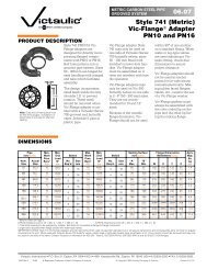
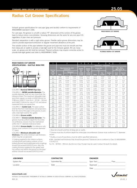
STANDARD AWWA GROOVE SPECIFICATIONS<strong>25.05</strong><strong>Radius</strong> <strong>Cut</strong> <strong>Groove</strong> <strong>Specifications</strong>Victaulic groove specifications for cast pipe (gray and ductile) conform to requirements ofANSI/AWWA standard C-606.For cast pipe, the groove is cut with a radius (“R” dimension) at the corners of the groovebase to reduce stress concentration. Grooving dimensions are the same for any one pipe O.D.regardless of pipe class and pressure.Standard preparation is with a rigid radius groove. Flexible radius groove dimensions may beused to provide expansion/contraction or angular movement allowance at the joint.The outside surface of the pipe between the groove and pipe end must be smooth and freefrom deep pits or swells to provide a leak-tight seat for the Victaulic gasket. All rust, loosescale, oil, grease and dirt shall be removed. Peened surfaces may require corrective action toprovide leak-tight gasket seal (refer to ANSI/AWWA C-606).RIGID RADIUS CUT GROOVEFLEXIBLE RADIUS CUT GROOVERIGID RADIUS CUT GROOVESPECIFICATIONS – DUCTILE IRON PIPEODBRABCExaggerated for clarityCOLUMN 1: Nominal AWWA Pipe Size.COLUMN 2 †: AWWA outside diameter. Theoutside diameter shall not vary more than thetolerance listed. The maximum allowable tolerancefrom square cut ends is 0.030"/0.8 mm for3"/80 mm; 0.045"/1.1 mm for 4 – 6"/100 – 150 mmand 0.060"/1.524 mm for sizes 8" O.D. and abovemeasured from true square line.COLUMN 3 †: Gasket seat. The pipe surfaceshall be free from indentations and projectionsfrom the end of the pipe to the groove, to providea leak-tight seat for the gasket.COLUMN 4: <strong>Groove</strong> width.COLUMN 5 †: <strong>Groove</strong> outside diameter. Thegroove must be uniform depth for the entirecircumference. <strong>Groove</strong> must be maintainedwithin the “C” diameter tolerance listed.COLUMN 6: <strong>Groove</strong> depth. For reference only.<strong>Groove</strong> must conform to the groove diameter“C” listed.COLUMN 7: Minimum allowable wallthickness. This is the minimum wall thicknesswhich may be cut grooved.† Coatings applied to the interior surfaces,including bolt pad mating surfaces, of ourbolted grooved and bolted plain end couplingsshould not exceed 0.010"/0.25 mm. Also, thecoating thickness applied to the gasket seatingsurface and within the groove on the pipeexterior should not exceed 0.010"/0.25 mm.T1 2 3 4 5 6 7NominalSizeInchesmmBasicPipe Outside Dia. O.D.Inches/mmTolerance*+ –GasketSeatA++0.000–0.020<strong>Groove</strong>WidthB+0.031–0.016Dimensions – Inches/mmBasic<strong>Groove</strong> Dia.C **Tol.+0.000<strong>Radius</strong>RMin. Allow.Wall Thick. T#3 3.96 +0.045 –0.045 0.840 0.375 3.723 –0.020 0.120 0.32 0.3180 100.6 +1.14 –1.14 21.34 9.53 94.56 –0.51 3.05 8.1 7.94 4.80 +0.045 –0.045 0.840 0.375 4.563 –0.020 0.120 0.35 0.32100 121.9 +1.14 –1.14 21.34 9.53 115.90 –0.51 3.05 8.9 8.16 6.90 +0.060 –0.060 0.840 0.375 6.656 –0.020 0.120 0.38 0.34150 175.3 +1.52 –1.52 21.34 9.53 169.06 –0.51 3.05 9.7 8.68 9.05 +0.060 –0.060 0.950 0.500 8.781 –0.025 0.145 0.41 0.36200 229.9 +1.52 –1.52 24.13 12.70 223.04 –0.64 3.68 10.4 9.110 11.10 +0.060 –0.060 1.015 0.500 10.813 –0.025 0.145 0.44 0.38250 281.9 +1.52 –1.52 25.78 12.70 274.65 –0.64 3.68 11.2 9.7CastIronDuctileIron12 13.20 +0.060 –0.060 1.015 0.500 12.906 –0.030 0.145 0.48 0.40300 335.3 +1.52 –1.52 25.78 12.70 327.81 –0.76 3.68 12.2 10.214 15.30 +0.050 –0.080 1.015 0.625 14.969 –0.030 0.165 0.55 0.42350 388.6 +1.27 –2.03 25.78 15.88 380.21 –0.76 4.19 14.0 10.716 17.40 +0.050 –0.080 1.340 0.625 17.063 –0.030 0.165 0.58 0.43400 442.0 +1.27 –2.03 34.04 15.88 433.40 –0.76 4.19 14.7 10.918 19.50 +0.050 –0.080 1.340 0.625 19.125 –0.030 0.185 0.63 0.44450 495.3 +1.27 –2.03 34.04 15.88 485.78 –0.76 4.70 16.0 11.220 21.60 +0.050 –0.080 1.340 0.625 21.219 –0.030 0.185 0.67 0.45500 548.6 +1.27 –2.03 34.04 15.88 538.96 –0.76 4.70 17.0 11.424 25.80 +0.050 –0.080 1.340 0.625 25.406 –0.030 0.185 0.73 0.47600 655.3 +1.27 –2.03 34.04 15.88 645.31 –0.76 4.70 18.5 11.930 32.00 +0.080 –0.060 1.625 0.750 31.550 –0.035 0.215 0.92 0.51750 812.8 +2.03 –1.52 41.28 19.05 801.37 –0.89 5.46 23.4 13.036 38.30 +0.080 –0.060 1.625 0.750 37.850 –0.035 0.215 1.02 0.58900 972.8 +2.03 –1.52 41.28 19.05 961.39 –0.89 5.46 25.9 14.7+ Must be smooth and free of deep pits or swells.** <strong>Groove</strong> must be of uniform depth for entire pipe circumference. <strong>Groove</strong> must conform to “C” diametershown.* Ovality, or out-of-roundness, must lie within specified tolerances.# Min. standard wall thickness that should be grooved. Tolerances are to conform to Class 53 ANSI/AWWAC151/A21.51.For 18 – 36"/450 – 950 mm ductile iron Class 53 pipe may be used. Contact Victaulic for details.JOB/OWNER CONTRACTOR ENGINEERSystem No._______________________________ Submitted By_____________________________ Spec Sect________________ Para____________Location_________________________________ Date ____________________________________ Approved_ _______________________________Date ____________________________________www.victaulic.comVICTAULIC IS A REGISTERED TRADEMARK OF VICTAULIC COMPANY. © 2009 VICTAULIC COMPANY. ALL RIGHTS RESERVED.REV_B<strong>25.05</strong>_1
STANDARD AWWA GROOVE SPECIFICATIONS<strong>Radius</strong> <strong>Cut</strong> <strong>Groove</strong> <strong>Specifications</strong><strong>25.05</strong>FLEXIBLE RADIUS CUT GROOVESPECIFICATIONS – DUCTILE IRON PIPEODBRABCCOLUMNExaggerated1: NominalforAWWAclarityPipe Size.COLUMN 2: AWWA outside diameter. Theoutside diameter shall not vary more than thetolerance listed. The maximum allowable tolerancefrom square cut ends is 0.030"/0.8 mm for3"/80 mm; 0.045"/1.1 mm for 4 – 6"/100 – 150 mmand 0.060"/1.524 mm for sizes 8" O.D. and abovemeasured from true square line.COLUMN 3: Gasket seat. The pipe surface shallbe free from indentations and projections fromthe end of the pipe to the groove, to provide aleak-tight seat for the gasket.COLUMN 4: <strong>Groove</strong> width.COLUMN 5: <strong>Groove</strong> outside diameter. Thegroove must be uniform depth for the entirecircumference. <strong>Groove</strong> must be maintainedwithin the “C” diameter tolerance listed.COLUMN 6: <strong>Groove</strong> depth. For reference only.<strong>Groove</strong> must conform to the groove diameter“C” listed.COLUMN 7: Minimum allowable wallthickness. This is the minimum wall thicknesswhich may be cut grooved.T1 2 3 4 5 6 7NominalSizeInchesmmBasicPipe Outside Dia. O.D.Inches/mmTolerance*+ –GasketSeatA++0.000–0.020<strong>Groove</strong>WidthB+0.031–0.016Dimensions – Inches/mmBasic<strong>Groove</strong> Dia.C **Tol.+0.000<strong>Radius</strong>RMin. Allow.Wall Thick. T#3 3.96 +0.045 –0.045 0.750 0.375 3.723 –0.020 0.120 0.32 0.3180 100.6 +1.14 –1.14 19.05 9.53 94.56 –0.51 3.05 8.1 7.94 4.80 +0.045 –0.045 0.750 0.375 4.563 –0.020 0.120 0.35 0.32100 121.9 +1.14 –1.14 19.05 9.53 115.90 –0.51 3.05 8.9 8.16 6.90 +0.060 –0.060 0.750 0.375 6.656 –0.020 0.120 0.38 0.34150 175.3 +1.52 –1.52 19.05 9.53 169.06 –0.51 3.05 9.7 8.68 9.05 +0.060 –0.060 0.875 0.500 8.781 –0.025 0.145 0.41 0.36200 229.9 +1.52 –1.52 22.23 12.70 223.04 –0.64 3.68 10.4 9.110 11.10 +0.060 –0.060 0.938 0.500 10.813 –0.025 0.145 0.44 0.38250 281.9 +1.52 –1.52 23.83 12.70 274.65 –0.64 3.68 11.2 9.7CastIronDuctileIron12 13.20 +0.060 –0.060 0.938 0.500 12.906 –0.030 0.145 0.48 0.40300 335.3 +1.52 –1.52 23.83 12.70 327.81 –0.76 3.68 12.2 10.214 15.30 +0.050 –0.080 0.938 0.625 14.969 –0.030 0.165 0.55 0.42350 388.6 +1.27 –2.03 23.83 15.88 380.21 –0.76 4.19 14.0 10.716 17.40 +0.050 –0.080 1.188 0.625 17.063 –0.030 0.165 0.58 0.43400 442.0 +1.27 –2.03 30.18 15.88 433.40 –0.76 4.19 14.7 10.918 19.50 +0.050 –0.080 1.188 0.625 19.125 –0.030 0.185 0.63 0.44450 495.3 +1.27 –2.03 30.18 15.88 485.78 –0.76 4.70 16.0 11.220 21.60 +0.050 –0.080 1.188 0.625 21.219 –0.030 0.185 0.67 0.45500 548.6 +1.27 –2.03 30.18 15.88 538.96 –0.76 4.70 17.0 11.424 25.80 +0.050 –0.080 1.188 0.625 25.406 –0.030 0.185 0.73 0.47600 655.3 +1.27 –2.03 30.18 15.88 645.31 –0.76 4.70 18.5 11.930 32.00 +0.080 –0.060 1.375 0.750 31.550 –0.035 0.215 0.92 0.51750 812.8 +2.03 –1.52 34.93 19.05 801.37 –0.89 5.46 23.4 13.036 38.30 +0.080 –0.060 1.375 0.750 37.850 –0.035 0.215 1.02 0.58900 972.8 +2.03 –1.52 34.93 19.05 961.39 –0.89 5.46 25.9 14.7+ Must be smooth and free of deep pits or swells.** <strong>Groove</strong> must be of uniform depth for entire pipe circumference. <strong>Groove</strong> must conform to “C” diametershown.* Ovality, or out-of-roundness, must lie within specified tolerances.# Min. standard wall thickness that should be grooved. Tolerances are to conform to Class 53 ANSI/AWWAC151/A21.51.For 18 – 36"/450 – 950 mm ductile iron Class 53 pipe may be used. Contact Victaulic for details.INSTALLATIONReference should always be made to the I-100 Victaulic Field Installation Handbook for the productyou are installing. Handbooks are included with each shipment of Victaulic products for completeinstallation and assembly data, and are available in PDF format on our website at www.victaulic.com.WARRANTYRefer to the Warranty section of the current Price List or contact Victaulic for details.NOTEThis product shall be manufactured by Victaulic or to Victaulic specifications. All products to beinstalled in accordance with current Victaulic installation/assembly instructions. Victaulic reserves theright to change product specifications, designs and standard equipment without notice and withoutincurring obligations.For complete contact information, visit www.victaulic.com<strong>25.05</strong> 1965 REV B UPDATED 8/2009VICTAULIC IS A REGISTERED TRADEMARK OF VICTAULIC COMPANY. © 2009 VICTAULIC COMPANY. ALL RIGHTS RESERVED.<strong>25.05</strong>