Proco 440-4400.pdf - Bay Port Valve & Fitting
Proco 440-4400.pdf - Bay Port Valve & Fitting
Proco 440-4400.pdf - Bay Port Valve & Fitting

You also want an ePaper? Increase the reach of your titles
YUMPU automatically turns print PDFs into web optimized ePapers that Google loves.
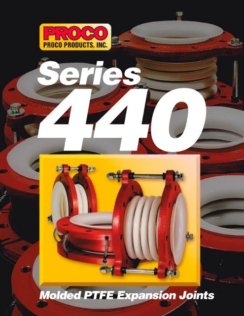
Series<strong>440</strong>Molded PTFE Expansion Joints
PROCO PRODUCTS, INC.The Expansion Joint PeoplePROCO Products, Inc. is the leading manufacturer of rubber,TEFLON ® , metal, and fabric connectors and expansion jointsin North America, and also offers the industry’s widestselection available.Our manufacturing history of expansion joints dates back to theold Uniroyal company, who invented the rubber expansion jointin 1930. PROCO Products, Inc., previously PROtective COatingsof Fort Wayne, Indiana, began marketing rubber expansion jointsunder its shortened name PROCO in 1980. Protective Coatingsmanufactured rubber expansion joints for Uniroyal under aprivate label arrangement from 1965 to 1979. In 1984 PROCOProducts acquired all assets of Protective Coatings—includingtooling, specifications and technologies used in producing rubberexpansion joints—and remains the sole property of PROCOProducts today.PROCO Products operates worldwide through a global agent anddistribution network providing a wide range of products andservices. This allows us to service the customer during all phasesof a project regardless of location. PROCO’s main goal is toprovide quality products and superior service to the demandingglobal marketplace.Quality and service will always be PROCO’s highest priority.TEFLON ® is a registered Trademark of E.I. Du Pont de Nemours and companyand is used under license by <strong>Proco</strong> Products, Inc.PROCO PRODUCTS, INC.PROCO PRODUCTS, Inc.2431 North Wigwam DriveStockton, California 95205Post Office Box 590Stockton, California 95201-0590 USAToll Free: 800 . 344 . 3246 USA/CanadaInternational: 209 . 943 . 6088Fax: 209 . 943 . 0242E-mail: sales@procoproducts.comWeb Site: www.procoproducts.comThe Expansion Joint PeopleCan Be Reached At Any Time!24-Hour Service FromOur Dedicated Staff!Steve BowmanTony DiazKathy WilsonKristen PereiraSylvia AugustoCal HayesMike LassasRob CoffeeScott WallaceEd MarcheseMerv VaterPROCO Products, Inc. Corporate Headquarters, Stockton, California.Demand the best — insist on PROCO!
SERIES<strong>440</strong>molded PTFE expansion jointsThe PROCO Series <strong>440</strong> PTFE Molded Expansion Joints are used for corrosive applicationsfound in: Chemical-Petrochemical, Industrial Process Piping Systems, Power GenerationPlants, Pulp/Paper Plants, Water-Wastewater Sewage and Pollution Control Systems wheremetallic joints/lap joints or PTFE & FEP-lined rubber expansion joints may have been previouslyused or specified. Specify PROCO Series <strong>440</strong> expansion joints for installation betweenanchor points or next to mechanical equipment such as: Absorption Machines, Blowers,Chillers, Fans, Graphite Heat Exchangers, Glass Lined Vessels, Pumps, and ExoticAlloy/Plastic/Glass Lined Piping Systems. The Series <strong>440</strong> expansion joints are designed to:(1) Absorb Pipe Movements/Stress, (2) Reduce System Noise, (3) Reduce Mechanical Vibration,(4) Compensate Alignment/Offset, (5) Eliminate Electrolysis, (6) Protect againstStart-up/Surge Forces. Our history in the manufacture of expansion joint products datesback to 1930. When an engineered solution is needed to solve a piping problem, call PROCO.Engineered For Your Application. The PROCO Series <strong>440</strong> PTFE expansion joints are availablein 2, 3, and 5 convolutions. Each convolution profile offers different overall lengths (face-tofacedimensions), movements and pressure/temperature rating to fit the required specification.Available styles include:• Style 442-BD: Features two convolutions for minimal movements, higher pressure/temperatureratings and short face-to-face opening requirements. Style 442-BD sizes range from1" to 24" diameter. (See Table 1)• Style 442-E: Features two convolutions, and is engineered with T-band compression limiters,limit cables (meets MIL-W-8342), and face-to-face lengths to be an exact equal toother more expensive, competitor models. Style 442-E sizes range from 1" to 12" diameter.(See Table 2)• Style 443-BD: Features three convolutions and is designed for moderate movement andease of system installation. Style 443-BD sizes range from 1" to 24" diameter. (See Table 3)• Style 443-E: Features three convolutions, and is engineered with T-band compression limiters,limit cables (meets MIL-W-8342), and face-to-face lengths to be an exact equal to other moreexpensive, competitor models. Style 443-E sizes range from 1" to 8" diameter. (See Table 4)• Style 445-BD: Features five convolutions, and is designed for maximum movements, lowpressure/temperature ranges, vibration reduction and greater face-to-face lengths. Style 445-BD sizes range from 1" to 20" diameter. (See Table 5)• Style 445-E: Features five convolutions, and is engineered with T-band compression limiters,limit cables (meets MIL-W-8342), and face-to-face lengths to be an exact equal to other moreexpensive, competitor models. Style 445-E sizes range from 1" to 6" diameter. (See Table 6)• Style <strong>440</strong>-BE: Features Styles’ <strong>440</strong>-E Neutral Lengths with Styles’ <strong>440</strong>-BD Limit Bolts.(See Table 7)Absorbs Pipe-Wall and Fluid-Borne Noise. The quiet operating PROCO Series <strong>440</strong> PTFE expansionjoints are a replacement for “sound transmitting” metallic/lap joints. Pipe Wall soundloses energy and is absorbed as the noise carried by the piping enters and exits the PTFEsection. Fluid-borne noise is absorbed by the volumetric expansion (breathing of the connector).This action cushions water hammer and smoothes out pumping impulses.Isolates Vibration and Motion. PROCO Series <strong>440</strong> PTFE expansion joints should be installedimmediately after and ahead of equipment generating vibration in order to isolate the rotating/vibratingequipment from the rest of the piping system. For optimum performance, thePROCO Series <strong>440</strong> PTFE expansion joints should be installed horizontally to the shaft. Verticaland perpendicular installations are also acceptable as these expansion joints will acceptaxial, lateral and angular movements as well as vibration. Note: For maximum vibration transmissionreduction, the pipe section beyond the PTFE expansion joints must be anchored orsufficiently rigid.Protecting Piping And EquipmentSystems From Stress/MotionReduces System Stress and Strain. Rigid attachment of piping to critical or mechanical equipmentcan produce excessive loading. Thermal or mechanically created strain-stress-shock arecushioned and absorbed with the installation of a flexible, low spring rate, PROCO Series <strong>440</strong>PTFE expansion joint. The PROCO Series <strong>440</strong> PTFE expansion joint adds a flexible componentto the system that automatically self-corrects for misalignment created by structural movementscaused by settling, pipe expansion or ground shifts.Tested Force Pound and Spring Rate Tables. At PROCO we have machine tested nearly everysize of the Series <strong>440</strong> PTFE expansion joints for Axial and Lateral Spring Rates and have providedThrust/Force factors so designers can properly design system restraints. It should benoted that the PROCO Series <strong>440</strong> PTFE expansion joints are in accordance with the performancecharacteristics of the Fluid Sealing Association’s Non-Metallic Expansion Joint Division.Superior “Flex Life” and Strength. The PROCO Series <strong>440</strong> PTFE expansion joints are contourmolded from extruded tubing providing superior “Flex Life” and Strength. Utilizing TEFLON®T-62 resins from DuPont, the PROCO Series <strong>440</strong> PTFE expansion joints provide dramaticallymore cycle life than that of PFA or FEP.Flange and Limit Bolts/Cables. All PROCO Series <strong>440</strong> PTFE expansion joint flange configurationsare coated with a rust inhibitive primer to prevent corrosion and are dimensionally tappedto ANSI 125/150# Standards. Hole drilling on center line, other drilling standards, or otherflange materials, such as 316 stainless, 304 stainless, or Epoxy Coated flanges are available onspecial order. In addition, all PROCO Series <strong>440</strong> PTFE expansion joints are supplied with factoryset limit bolts or cables to prevent over-extension during operation.Chemical Service Capability at Minimal Cost. Expensive, exotic metal, PTFE or FEP linedrubber expansion joints for severe chemical service can be replaced with the low cost PROCOSeries <strong>440</strong> PTFE expansion joints. The PTFE bellows are van stoned to the flanges which allowsall wetted surfaces to come in contact with only the PTFE material. Specify the PROCOSeries <strong>440</strong> PTFE expansion joints where high temperatures coupled with lower pressures orlower temperatures coupled with higher pressures are proposed. The PROCO Series <strong>440</strong> PTFEoffers the lowest cost expansion joint that is impervious to chemical attack. Use the PROCO“Chemical to Elastomer Guide” for reference on chemical compatibility.Services and Locations. PROCO Series <strong>440</strong> PTFE Expansion Joints have been supplied andsuccessfully used by a range of customers worldwide in the process industries for use inboth organic and inorganic chemical processing and production, including such demandingapplications as agrochemical and pharmaceutical chemical production, acid processing andfood manufacture.Information • Ordering • Pricing • Delivery. Day or night, weekends and holidays…the PROCOphones are monitored 24 hours around the clock. When you have a question, you can call us.Toll-Free Phone . . . . . . . . . 800 / 344-3246 USA/CANADAInternational Calls . . . . . . . 209 / 943-6088Fax . . . . . . . . . . . . . . . . . . . 209 / 943-0242Email . . . . . . . . . . . . . . . . . sales@procoproducts.comWebsite . . . . . . . . . . . . . . . www.procoproducts.comWeekday office hours are 5:30 a.m. to 5:15 p.m. Pacific Time.© PROCO PRODUCTS, INC.Rev. 2 1/07
STYLE442-BDmolded PTFE expansion jointsTable 1: Sizes • Movements • Spring Rates • Flange Standards • Temperatures • Vacuum • WeightsNOMINALSIZE I.D.1.001.251.502.002.503.004.005.006.008.0010.0012.0014.0016.0018.0020.0024.00NEUTRAL LENGTHINCHESElasticStop NutNominal Pipe SizeJoint I.D.MOVEMENT CAPABILITIESBASED ON TWOCONVOLUTION DESIGN 1± AXIAL (∆x)MOVEMENTLATERAL (∆y)DEFLECTIONANGULARDEFLECTIONNeutral LengthCOMPRESSIONSPRING RATESPRING RATE CAPABILITY 2EXTENSIONSPRING RATEWasherReinforcingRingNeopreneGrommetLATERALSPRING RATETHRUST FACTOR# HOLESNominalFlangeDiameterTHREADEDHOLE SIZEPTFEFlare O.D."B"BOLT CIRCLEFLANGE “A”EXPANSION JOINT FLANGE DRILLINGThreaded Hole Size(ANSI) StandardFLANGETHICKNESSNOMINAL FLANGEO.D.Limit Bolt"Ear" O.D.LIMIT BOLTDIAMETERBolt CircleFlange "A"NominalSize I.D.BOLT CIRCLELIMIT BOLT “C”LIMIT BOLT“EAR” O.D.PRESSURE AT TEMPERATURE(PSIG) @ °FIN IN DEG. LB f /IN LB f /IN LB f /IN70° 100° 150° 200° 250° 300° 350° 400°Hg atTemp.1.375 0.250 .125 7 104 80 104 2.76 4 1/2- 13 3.125 2.000 .313 4.250 .250 5.125 6.000 185 170 148 130 115 100 84 68 29.9" @425°F21.375 0.250 .125 7 61 137 400 2.25 4 1/2- 13 3.500 2.520 .394 4.630 .250 5.196 6.850 185 170 148 130 115 100 84 68 CF 51.375 0.250 .125 7 320 180 224 4.60 4 1/2- 13 3.875 2.875 .344 5.000 .250 5.875 6.750 185 170 148 130 115 100 84 6829.9" @425°F31.563 0.250 .125 7 512 300 240 7.07 4 5/8- 11 4.750 3.625 .438 6.000 .375 6.875 8.125 185 170 148 130 115 100 84 6829.9" @425°F72.250 0.313 .125 7 457 278 328 9.62 4 5/8- 11 5.500 4.125 .500 7.000 .375 8.125 9.375 185 170 148 130 115 100 84 68 29.9" @425°F102.250 0.375 .188 7 648 320 319 15.90 4 5/8- 11 6.000 5.000 .500 7.500 .375 8.750 10.000 185 170 148 130 115 100 84 6829.9" @425°F102.625 0.500 .250 7 480 280 400 23.75 8 5/8- 11 7.500 6.188 .625 9.000 .375 9.875 11.125 185 170 148 130 115 100 84 6829.9" @400°F183.250 0.500 .250 7 <strong>440</strong> <strong>440</strong> 320 33.17 8 3/4- 10 8.500 7.313 .750 10.000 .500 11.500 13.000 185 170 148 130 115 100 84 6829.9" @400°F242.750 0.500 .250 7 <strong>440</strong> 386 <strong>440</strong> 50.24 8 3/4- 10 9.500 8.500 .750 11.000 .500 12.500 14.000 185 170 148 130 115 100 84 68 29.9" @400°F294.000 0.500 .250 7 450 390 480 83.49 8 3/4- 10 11.750 10.625 .938 13.500 .500 14.750 16.250 164 150 129 112 100 87 73 6029.9" @250°F475.250 0.500 .250 7 760 600 580 108.38 12 7/8- 9 14.250 12.750 1.000 16.000 .500 17.500 19.000 164 150 129 112 100 87 73 6029.9" @250°F646.000 0.500 .250 7 1300 420 700 176.63 12 7/8- 9 17.000 15.000 1.000 19.000 .625 20.500 22.000 70 59 48 40 35 30 26 2229.9" @75°F1156.313 0.750 .375 7 320 1056 1256 233.59 12 1- 8 18.750 16.250 1.188 21.000 1.420 24.172 27.313 70 59 48 40 35 30 26 2210.0" @212°F1267.000 1.000 .375 7 297 1096 1256 259.68 16 1- 8 21.250 18.500 1.188 23.500 1.420 27.563 31.500 70 59 48 40 35 30 26 2210.0" @212°F1597.938 1.000 .375 7 <strong>440</strong> 1941 1370 321.90 16 1 1/8- 8 22.750 21.000 1.188 25.000 1.420 29.000 32.906 70 59 48 40 35 30 26 229.0" @212°F1749.000 1.000 .375 7 — — — 374.57 20 1 1/8- 8 25.000 23.000 1.188 27.500 1.420 31.500 35.438 70 59 48 40 35 30 26 226.0" @212°F1836.313 0.625 .375 7 — — — 538.36 20 1 1/4- 7 29.500 27.250 1.344 32.000 1.420 35.906 39.844 70 59 48 40 35 30 26 224.0" @212°F238NOTES: 1. Movements are non-concurrent and based from Neutral Length with Limit Bolts installed.2. Spring Rate Capability is based on 1" of movement at zero pressure conditions.3. Vacuum Rating is based from fully extended position. CF = Contact Factory.PTFE FLAREO.D. “B”SERIES 442-BDMATERIALS OF CONSTRUCTIONVACUUM RATING 3DESCRIPTION 1" THROUGH 12" 14" THROUGH 24"BELLOWS PTFE T-62 PTFE T-62WEIGHT / LBSFLANGES DUCTILE IRON ZINC PLATED CARBON STEELREINFORCING RINGS STAINLESS STEEL STAINLESS STEELLIMIT BOLTS CARBON STEEL CARBON STEELNUTS CARBON STEEL CARBON STEELFactory SetLimit BoltMoldedPTFE T-62BellowsFlange(ANSI) StandardBolt CircleLimit Bolt "C"GROMMETS NEOPRENE NEOPRENEWASHERS CARBON STEEL CARBON STEEL
STYLE442-Emolded PTFE expansion jointsTable 2: Sizes • Movements • Spring Rates • Flange Standards • Temperatures • Vacuum • WeightsNOMINALSIZE I.D.NEUTRAL LENGTHINCHESMOVEMENT CAPABILITIESBASED ON TWOCONVOLUTION DESIGN 1± AXIAL (∆x)MOVEMENTLATERAL (∆y)DEFLECTIONANGULARDEFLECTIONCOMPRESSIONSPRING RATESPRING RATE CAPABILITY 2EXTENSIONSPRING RATELATERALSPRING RATETHRUST FACTOR# HOLESTHREADEDHOLE SIZEEXPANSION JOINT FLANGE DRILLINGBOLT CIRCLEFLANGE “A”PRESSURE AT TEMPERATURE(PSIG) @ °FIN IN DEG. LB f /IN LB f /IN LB f /IN70° 100° 150° 200° 250° 300° 350° 400°PTFE FLAREO.D. “B”FLANGETHICKNESSNOMINAL FLANGEO.D.VACUUM RATING 3Hg atTemp.WEIGHT / LBS1.0029.9" @1.750 0.344 .250 16 140 144 120 2.76 4 1/2- 13 3.125 2.000 .438 4.250 185 170 148 130 115 100 84 68 3425°F1.5029.9" @1.813 0.344 .250 13 240 200 240 4.60 4 1/2- 13 3.875 2.875 .469 5.000 185 170 148 130 115 100 84 68 4425°F2.0029.9" @1.875 0.344 .281 12 430 350 <strong>440</strong> 7.07 4 5/8- 11 4.750 3.625 .484 6.000 185 170 148 130 115 100 84 68 7425°F3.0029.9" @2.188 0.406 .313 10 650 320 350 15.90 4 5/8- 11 6.000 5.000 .578 7.500 185 170 148 130 115 100 84 68 10425°F4.0029.9" @2.281 0.438 .313 9 360 280 630 23.75 8 5/8- 11 7.500 6.188 .578 9.000 185 170 148 130 115 100 84 68 17400°F6.0029.9" @2.531 0.469 .375 7 460 350 720 50.24 8 3/4- 10 9.500 8.500 .641 11.000 185 170 148 130 115 100 84 68 27400°F8.0029.9" @2.750 0.531 .406 6 300 230 800 81.48 8 3/4- 10 11.750 10.625 .688 13.500 164 150 129 112 100 87 73 60 35250°F10.0029.9" @2.969 0.563 .438 5 1280 870 1000 108.38 12 7/8- 9 14.250 12.750 .734 16.000 164 150 129 112 100 87 73 60 52250°F12.0029.9" @3.094 0.594 .469 5 380 240 1000 176.63 12 7/8- 9 17.000 15.000 .813 19.000 70 59 48 40 35 30 26 22 10775°FNOTES: 1. Movements are non-concurrent and based from Neutral Length with Limit Cables installed.2. Spring Rate Capability is based on 1" of movement at zero pressure conditions.3. Vacuum Rating is based from fully extended position.Nominal Pipe SizeJoint I.D.Neutral LengthLimit CableT-BandReinforcingRingNominalFlangeDiameterPTFEFlare O.D."B"Threaded Hole Size(ANSI) StandardBolt CircleFlange "A"NominalSize I.D.SERIES 442-EMATERIALS OF CONSTRUCTIONDESCRIPTION 1" THROUGH 12"BELLOWS PTFE T-62FLANGESREINFORCING RINGSDUCTILE IRONSTAINLESS STEELMoldedPTFE T-62BellowsFlange(ANSI) StandardT-BANDSLIMIT CABLESCARBON STEELMIL-W-8342
STYLE443-BDmolded PTFE expansion jointsTable 3: Sizes • Movements • Spring Rates • Flange Standards • Temperatures • Vacuum • WeightsNOMINALSIZE I.D.NEUTRAL LENGTHINCHESElasticStop NutNominal Pipe SizeJoint I.D.MOVEMENT CAPABILITIESBASED ON THREECONVOLUTION DESIGN 1± AXIAL (∆x)MOVEMENTLATERAL (∆y)DEFLECTIONANGULARDEFLECTIONNeutral LengthCOMPRESSIONSPRING RATESPRING RATE CAPABILITY 2EXTENSIONSPRING RATEWasherReinforcingRingNeopreneGrommetLATERALSPRING RATETHRUST FACTOR# HOLESNominalFlangeDiameterTHREADEDHOLE SIZEPTFEFlare O.D."B"BOLT CIRCLEFLANGE “A”EXPANSION JOINT FLANGE DRILLINGThreaded Hole Size(ANSI) StandardFLANGETHICKNESSNOMINAL FLANGEO.D.Limit Bolt"Ear" O.D.LIMIT BOLTDIAMETERBolt CircleFlange "A"NominalSize I.D.BOLT CIRCLELIMIT BOLT “C”LIMIT BOLT“EAR” O.D.PRESSURE AT TEMPERATURE(PSIG) @ °FIN IN DEG. LB f /IN LB f /IN LB f /IN70° 100° 150° 200° 250° 300° 350° 400°Hg atTemp.1.00 1.750 0.500 .250 14 190 82 96 2.81 4 1/2- 13 3.125 2.000 .313 4.250 .250 5.125 6.000 138 126 107 90 76 64 53 45 29.9" @400°F21.251.502.001.8102.0002.7500.5000.5000.750.250.250.37514141<strong>440</strong>846912066763141081092.255.099.114441/2- 131/2- 135/8- 113.5003.8754.7502.5202.8753.625.394.344.4384.6305.0006.000.250.250.3755.1965.8756.8756.8506.7508.12512813813812012612696107107859090727676566464425353364545CF29.9" @400°F29.9" @400°F5482.50 3.188 0.750 .375 14 91 97 160 11.41 4 5/8- 11 5.500 4.125 .500 7.000 .375 8.125 9.375 138 126 107 90 76 64 53 45 29.9" @400°F3.00 3.625 1.000 .500 14 124 125 194 16.91 4 5/8- 11 6.000 5.000 .500 7.500 .375 8.750 10.000 138 126 107 90 76 64 53 4529.9" @400°F29.9" @4.00 3.625 1.000 .500 14 220 155 264 25.40 8 5/8- 11 7.500 6.188 .625 9.000 .375 9.875 11.125 138 126 107 90 76 64 53 45400°F1113195.00 4.000 1.000 .500 14 320 210 324 34.45 8 3/4- 10 8.500 7.313 .750 10.000 .500 11.500 13.000 138 126 107 90 76 64 53 4529.9" @300°F256.00 4.000 1.125 .563 14 289 187 266 50.24 8 3/4- 10 9.500 8.500 .750 11.000 .500 12.500 14.000 138 126 107 90 76 64 53 45 29.9" @300°F29.9" @8.00 6.000 1.125 .563 14 178 218 423 83.49 8 3/4- 10 11.750 10.625 .938 13.500 .500 14.750 16.250 120 110 94 80 67 57 47 38125°F19.0" @10.00 7.000 1.188 .500 14 420 531 857 128.55 12 7/8- 9 14.250 12.750 1.000 16.000 .500 17.500 19.000 82 70 64 52 46 39 34 30212°F30486012.0014.0016.007.8758.5009.1881.1881.2501.375.625.688.750141414743239245542628571857970970144.72233.59259.681212167/8- 91- 81- 817.00018.75021.25015.000 1.00016.250 1.18818.500 1.18819.00021.00023.500.6251.4201.42020.50024.17227.56322.00027.31331.50082828270707064646452525246464640404034343430303010.0" @212°F10.0" @212°F10.0" @212°F771321659.0" @18.00 11.063 1.188 .750 14 — — 1085 321.90 16 1 1/8- 8 22.750 21.000 1.188 25.000 1.420 29.000 32.906 60 58 48 42 36 30 28 26212°F20120.00 12.875 1.188 1.000 14 — — 1142 374.57 20 1 1/8- 8 25.000 23.000 1.188 27.500 1.420 31.500 35.438 60 58 48 42 36 30 28 266.0" @212°F2434.0" @24.00 11.875 1.000 .750 14 — — — 538.36 20 1 1/4- 7 29.500 27.250 1.344 32.000 1.420 35.906 39.844 60 58 48 42 36 30 28 26212°F309NOTES: 1. Movements are non-concurrent and based from Neutral Length with Limit Bolts installed.2. Spring Rate Capability is based on 1" of movement at zero pressure conditions.3. Vacuum Rating is based from fully extended position. CF = Contact Factory.PTFE FLAREO.D. “B”VACUUM RATING 3SERIES 443-BDMATERIALS OF CONSTRUCTIONDESCRIPTION 1" THROUGH 12" 14" THROUGH 24"BELLOWS PTFE T-62 PTFE T-62WEIGHT / LBSFLANGES DUCTILE IRON ZINC PLATED CARBON STEELREINFORCING RINGS STAINLESS STEEL STAINLESS STEELLIMIT BOLTS CARBON STEEL CARBON STEELNUTS CARBON STEEL CARBON STEELFactory SetLimit BoltMoldedPTFE T-62BellowsFlange(ANSI) StandardBolt CircleLimit Bolt "C"GROMMETS NEOPRENE NEOPRENEWASHERS CARBON STEEL CARBON STEEL
STYLE443-Emolded PTFE expansion jointsTable 4: Sizes • Movements • Spring Rates • Flange Standards • Temperatures • Vacuum • WeightsNOMINALSIZE I.D.NEUTRAL LENGTHINCHESMOVEMENT CAPABILITIESBASED ON THREECONVOLUTION DESIGN 1± AXIAL (∆x)MOVEMENTLATERAL (∆y)DEFLECTIONANGULARDEFLECTIONCOMPRESSIONSPRING RATESPRING RATE CAPABILITY 2EXTENSIONSPRING RATELATERALSPRING RATETHRUST FACTOR# HOLESTHREADEDHOLE SIZEEXPANSION JOINT FLANGE DRILLINGBOLT CIRCLEFLANGE “A”PRESSURE AT TEMPERATURE(PSIG) @ °FIN IN DEG. LB f /IN LB f /IN LB f /IN70° 100° 150° 200° 250° 300° 350° 400°PTFE FLAREO.D. “B”FLANGETHICKNESSNOMINAL FLANGEO.D.VACUUM RATING 3Hg atTemp.WEIGHT / LBS1.0029.9" @2.313 0.500 .375 24 130 130 260 2.81 4 1/2- 13 3.125 2.000 .438 4.250 138 126 107 90 76 64 53 45 3400°F1.5029.9" @2.406 0.531 .375 20 80 70 110 5.09 4 1/2- 13 3.875 2.875 .469 5.000 138 126 107 90 76 64 53 45 5400°F2.0029.9" @2.500 0.531 .406 17 70 80 160 9.11 4 5/8- 11 4.750 3.625 .484 6.000 138 126 107 90 76 64 53 45 8400°F3.0029.9" @2.906 0.625 .469 15 140 160 190 16.91 4 5/8- 11 6.000 5.000 .578 7.500 138 126 107 90 76 64 53 45 1<strong>440</strong>0°F4.0029.9" @3.063 0.656 .500 13 220 160 190 25.40 8 5/8- 11 7.500 6.188 .578 9.000 138 126 107 90 76 64 53 45 19400°F6.0029.9" @3.375 0.719 .531 10 350 190 540 50.24 8 3/4- 10 9.500 8.500 .641 11.000 138 126 107 90 76 64 53 45 30300°F8.0029.9" @3.656 0.781 .594 9 450 170 750 81.48 8 3/4- 10 11.750 10.625 .688 13.500 120 110 94 80 67 57 47 38 39125°FNOTES: 1. Movements are non-concurrent and based from Neutral Length with Limit Cables installed.2. Spring Rate Capability is based on 1" of movement at zero pressure conditions.3. Vacuum Rating is based from fully extended position.Nominal Pipe SizeJoint I.D.Neutral LengthLimit CableT-BandReinforcingRingNominalFlangeDiameterPTFEFlare O.D."B"Threaded Hole Size(ANSI) StandardBolt CircleFlange "A"NominalSize I.D.SERIES 443-EMATERIALS OF CONSTRUCTIONDESCRIPTION 1" THROUGH 8"BELLOWS PTFE T-62FLANGESREINFORCING RINGSDUCTILE IRONSTAINLESS STEELMoldedPTFE T-62BellowsFlange(ANSI) StandardT-BANDSLIMIT CABLESCARBON STEELMIL-W-8342
STYLE445-BDmolded PTFE expansion jointsTable 5: Sizes • Movements • Spring Rates • Flange Standards • Temperatures • Vacuum • WeightsNOMINALSIZE I.D.NEUTRAL LENGTHINCHESMOVEMENT CAPABILITIESBASED ON FIVECONVOLUTION DESIGN 1± AXIAL (∆x)MOVEMENTLATERAL (∆y)DEFLECTIONANGULARDEFLECTIONCOMPRESSIONSPRING RATESPRING RATE CAPABILITY 2EXTENSIONSPRING RATELATERALSPRING RATETHRUST FACTOR# HOLESTHREADEDHOLE SIZEBOLT CIRCLEFLANGE “A”EXPANSION JOINT FLANGE DRILLINGPTFE FLAREO.D. “B”FLANGETHICKNESSPRESSURE AT TEMPERATURE(PSIG) @ °FIN IN DEG. LB f /IN LB f /IN LB f /IN70° 100° 150° 200° 250° 300° 350° 400°NOMINAL FLANGEO.D.LIMIT BOLTDIAMETERBOLT CIRCLELIMIT BOLT “C”LIMIT BOLT“EAR” O.D.VACUUM RATING 3Hg atTemp.WEIGHT / LBS1.001.251.502.002.503.004.005.006.008.0010.0012.0014.0016.003.000 0.500 .500 20 30 44 22 2.81 4 1/2- 13 3.125 2.000 .313 4.250 .250 5.125 6.000 72 61 46 40 34 29 27 24 22.670 0.394 .470 20 36 114 171 2.25 4 1/2- 13 3.500 2.520 .394 4.630 .250 5.196 6.850 62 56 42 36 30 26 22 22 5NOT3.500 0.750 .500 20 75 83 46 5.09 4 1/2- 13 3.875 2.875 .344 5.000 .250 5.875 6.750 72 61 46 40 34 29 27 24 54.000 1.000 .500 20 60 47 50 9.11 4 5/8- 11 4.750 3.625 .438 6.000 .375 6.875 8.125 72 61 46 40 34 29 27 24 94.600 0.980 .510 20 116 319 285 10.08 4 5/8- 11 5.500 4.125 .500 7.000 .375 8.125 9.375 62 56 42 36 30 26 22 22 11DESIGNED5.000 1.000 .500 20 55 60 170 16.91 4 5/8- 11 6.000 5.000 .500 7.500 .375 8.750 10.000 72 61 46 40 34 29 27 24 145.250 1.250 .625 20 72 60 80 25.40 8 5/8- 11 7.500 6.188 .625 9.000 .375 9.875 11.125 72 61 46 40 34 29 27 24 206.0006.0001.2501.250.625.625202014019038813040019532.3350.24883/4- 103/4- 108.5009.5007.3138.500.750.75010.00011.000.500.50011.50012.50013.00014.00062725661424636403034262922272224FOR 26318.000 1.250 .625 20 304 388 457 76.07 8 3/4- 10 11.750 10.625 .938 13.500 .500 14.750 16.250 48 42 34 30 26 22 22 22 49VACUUM8.750 1.250 .625 20 458 388 457 128.55 12 7/8- 9 14.250 12.750 1.000 16.000 .500 17.500 19.000 48 42 34 30 26 22 22 22 649.000 1.375 .688 20 529 445 457 144.72 12 7/8- 9 17.000 15.000 1.000 19.000 .625 20.500 22.000 48 42 34 30 26 22 22 22 8812.790 1.375 .688 20 203 371 514 233.59 12 1- 8 18.750 16.250 1.188 21.000 1.420 24.172 27.313 48 42 34 30 26 22 22 22 14313.500 1.625 1.000 20 180 383 514 259.68 16 1- 8 21.250 18.500 1.188 23.500 1.420 27.563 31.500 48 42 34 30 26 22 22 22 179SERVICE20.00 20.470 1.625 1.000 20 185 371 571 374.57 20 1 1/8- 8 25.000 23.000 1.188 27.500 1.420 31.500 35.438 48 42 34 30 26 22 22 22 243NOTES: 1. Movements are non-concurrent and based from Neutral Length with Limit Bolts installed.2. Spring Rate Capability is based on 1" of movement at zero pressure conditions.3. Style 445-BD is not designed for Vacuum Service.ElasticStop NutNominal Pipe SizeJoint I.D.Neutral LengthWasherReinforcingRingNeopreneGrommetNominalFlangeDiameterPTFEFlare O.D."B"Threaded Hole Size(ANSI) StandardLimit Bolt"Ear" O.D.Bolt CircleFlange "A"NominalSize I.D.SERIES 445-BDMATERIALS OF CONSTRUCTIONDESCRIPTION 1" THROUGH 12" 14" THROUGH 20"BELLOWS PTFE T-62 PTFE T-62FLANGES DUCTILE IRON ZINC PLATED CARBON STEELREINFORCING RINGS STAINLESS STEEL STAINLESS STEELLIMIT BOLTS CARBON STEEL CARBON STEELNUTS CARBON STEEL CARBON STEELFactory SetLimit BoltMoldedPTFE T-62BellowsFlange(ANSI) StandardBolt CircleLimit Bolt "C"GROMMETS NEOPRENE NEOPRENEWASHERS CARBON STEEL CARBON STEEL
STYLE445-Emolded PTFE expansion jointsTable 6: Sizes • Movements • Spring Rates • Flange Standards • Temperatures • Vacuum • WeightsNOMINALSIZE I.D.NEUTRAL LENGTHINCHESMOVEMENT CAPABILITIESBASED ON FIVECONVOLUTION DESIGN 1± AXIAL (∆x)MOVEMENTLATERAL (∆y)DEFLECTIONANGULARDEFLECTIONCOMPRESSIONSPRING RATESPRING RATE CAPABILITY 2EXTENSIONSPRING RATELATERALSPRING RATETHRUST FACTOR# HOLESTHREADEDHOLE SIZEEXPANSION JOINT FLANGE DRILLINGBOLT CIRCLEFLANGE “A”PRESSURE AT TEMPERATURE(PSIG) @ °FIN IN DEG. LB f /IN LB f /IN LB f /IN70° 100° 150° 200° 250° 300° 350° 400°PTFE FLAREO.D. “B”FLANGETHICKNESSNOMINAL FLANGEO.D.VACUUM RATING 3Hg atTemp.WEIGHT / LBS1.003.500 0.844 .625 39 50 110 50 2.81 4 1/2- 13 3.125 2.000 .438 4.250 72 61 46 40 34 29 27 24 3NOT1.503.625 0.875 .656 32 75 80 50 5.09 4 1/2- 13 3.875 2.875 .469 5.000 72 61 46 40 34 29 27 24 7DESIGNED2.003.750 0.875 .656 29 60 50 50 9.11 4 5/8- 11 4.750 3.625 .484 6.000 72 61 46 40 34 29 27 24 10FOR3.004.375 1.031 .781 25 55 60 170 16.91 4 5/8- 11 6.000 5.000 .578 7.500 72 61 46 40 34 29 27 24 16VACUUM4.004.563 1.094 .813 21 70 60 80 25.40 8 5/8- 11 7.500 6.188 .578 9.000 72 61 46 40 34 29 27 24 236.00SERVICE5.031 1.188 .906 17 190 130 195 50.24 8 3/4- 10 9.500 8.500 .641 11.000 72 61 46 40 34 29 27 24 34NOTES: 1. Movements are non-concurrent and based from Neutral Length with Limit Cables installed.2. Spring Rate Capability is based on 1" of movement at zero pressure conditions.3. Style 445-E is not designed for Vacuum Service.Nominal Pipe SizeJoint I.D.Neutral LengthLimit CableT-BandReinforcingRingNominalFlangeDiameterPTFEFlare O.D."B"Threaded Hole Size(ANSI) StandardBolt CircleFlange "A"NominalSize I.D.SERIES 445-EMATERIALS OF CONSTRUCTIONDESCRIPTION 1" THROUGH 6"BELLOWS PTFE T-62FLANGESREINFORCING RINGSDUCTILE IRONSTAINLESS STEELMoldedPTFE T-62BellowsFlange(ANSI) StandardT-BANDSLIMIT CABLESCARBON STEELMIL-W-8342
STYLE<strong>440</strong>-BEmolded PTFE expansion jointsTable 7: Sizes • Movements • Spring Rates • Flange Standards • Temperatures • Vacuum • WeightsNOMINALSIZE I.D.NEUTRAL LENGTHINCHES± AXIAL (∆x)MOVEMENT(<strong>440</strong>-E Neutral Lengths with <strong>440</strong>-BD Limit Bolts)MOVEMENTCAPABILITIES 1 SPRING RATE CAPABILITY 2EXPANSION JOINT FLANGE DRILLING PRESSURE AT TEMPERATURE(PSIG) @ °FLATERAL (∆y)DEFLECTIONANGULARDEFLECTIONCOMPRESSIONSPRING RATEEXTENSIONSPRING RATELATERALSPRING RATETHRUST FACTOR# HOLESTHREADEDHOLE SIZEBOLT CIRCLEFLANGE “A”PTFE FLAREO.D. “B”IN IN DEG. LB f /IN LB f /IN LB f /IN70° 100° 150° 200° 250° 300° 350° 400°Style 442-BE — 442-E Neutral Lengths with 442-BD Limit Bolts1.00 1.750 0.344 .125 7 140 144 120 2.76 4 1/2- 13 3.125 2.000 .438 4.250 .250 5.125 6.000 185 170 148 130 115 100 84 6829.9" @425°F229.9" @1.50 1.813 0.344 .125 7 240 200 240 4.60 4 1/2- 13 3.875 2.875 .469 5.000 .250 5.875 6.750 185 170 148 130 115 100 84 68425°F229.9" @2.00 1.875 0.344 .125 7 430 350 <strong>440</strong> 7.07 4 5/8- 11 4.750 3.625 .484 6.000 .375 6.875 8.125 185 170 148 130 115 100 84 68425°F729.9" @3.00 2.188 0.406 .188 7 650 320 350 15.90 4 5/8- 11 6.000 5.000 .578 7.500 .375 8.750 10.000 185 170 148 130 115 100 84 68425°F104.00 2.281 0.438 .250 7 360 280 630 23.75 8 5/8- 11 7.500 6.188 .578 9.000 .375 9.875 11.125 185 170 148 130 115 100 84 6829.9" @400°F186.00 2.531 0.469 .250 7 460 350 720 50.24 8 3/4- 10 9.500 8.500 .641 11.000 .500 12.500 14.000 185 170 148 130 115 100 84 6829.9" @400°F298.00 2.750 0.531 .250 7 300 230 800 81.48 8 3/4- 10 11.750 10.625 .688 13.500 .500 14.750 16.250 164 150 129 112 100 87 73 6029.9" @250°F4710.00 2.969 0.563 .250 6 1280 870 1000 108.38 12 7/8- 9 14.250 12.750 0.734 16.000 .500 17.500 19.000 164 150 129 112 100 87 73 6029.9" @250°F6412.00 3.094 0.594 .250 5 380 240 1000 176.63 12 7/8- 9 17.000 15.000 0.813 19.000 .625 20.500 22.000 70 59 48 40 35 30 26 2229.9" @75°F115Style 443-BE — 443-E Neutral Lengths with 443-BD Limit Bolts29.9" @1.00 2.313 0.500 .250 14 130 130 260 2.81 4 1/2- 13 3.125 2.000 .438 4.250 .250 5.125 6.000 138 126 107 90 76 64 53 45400°F21.502.003.004.006.002.4062.5002.9063.0633.3750.5310.5310.6250.6560.719.250.375.500.500.563121210109807014022035070801601601901101601901905405.099.1116.9125.4050.24444881/2- 135/8- 115/8- 115/8- 113/4- 103.8754.7506.0007.5009.5002.8753.6255.0006.1888.500.469.484.578.578.6415.0006.0007.5009.00011.000.250.375.375.375.5005.8756.8758.7509.87512.5006.7508.12510.00011.12514.0001381381381381381261261261261261071071071071079090909090767676767664646464645353535353454545454529.9" @400°F29.9" @400°F29.9" @400°F29.9" @400°F29.9" @300°F4813193029.9" @8.00 3.656 0.781 .563 9 450 170 750 81.48 8 3/4- 10 11.750 10.625 .688 13.500 .500 14.750 16.250 120 110 94 80 67 57 47 38125°F48Style 445-BE — 445-E Neutral Lengths with 445-BD Limit BoltsFLANGETHICKNESSNOMINAL FLANGEO.D.LIMIT BOLTDIAMETERBOLT CIRCLELIMIT BOLT “C”LIMIT BOLT“EAR” O.D.VACUUM RATING 3Hg atTemp.WEIGHT / LBS1.001.502.003.004.006.003.5003.6250.8<strong>440</strong>.785.500.500202050751108050502.815.09441/2- 131/2- 133.1253.8752.0002.875.438.4694.2505.000.250.2505.1255.8756.0006.75072726161464640403434292927272424NOT253.750 0.875 .500 15 60 50 50 9.11 4 5/8- 11 4.750 3.625 .484 6.000 .375 6.875 8.125 72 61 46 40 34 29 27 24DESIGNED94.375 1.031 .500 17 55 60 170 16.91 4 5/8- 11 6.000 5.000 .578 7.500 .375 8.750 10.000 72 61 46 40 34 29 27 24FOR144.563 1.094 .625 15 70 60 80 25.40 8 5/8- 11 7.500 6.188 .578 9.000 .375 9.875 11.125 72 61 46 40 34 29 27 24VACUUM20SERVICE5.031 1.188 .625 15 190 130 195 50.24 8 3/4- 10 9.500 8.500 .641 11.000 .500 12.500 14.000 72 61 46 40 34 29 27 24 31NOTES: 1. Movements are non-concurrent and based from Neutral Length with Limit Bolts installed.2. Spring Rate Capability is based on 1" of movement at zero pressure conditions.3. Vacuum Rating is based from fully extended position. Style 445-BE is not designed for Vacuum Service.PROCO STYLE NUMBER:442-BE — 1" THROUGH 12"443-BE — 1" THROUGH 8"445-BE — 1" THROUGH 6"STYLE <strong>440</strong>-BE MATERIALS OF CONSTRUCTIONBELLOWS FLANGES REINFORCING RINGS LIMIT BOLTS NUTS GROMMETS WASHERSPTFE T-62 DUCTILE IRON STAINLESS STEEL CARBON STEEL CARBON STEEL NEOPRENE CARBON STEEL
Installation Instructions for Series <strong>440</strong> PTFE Expansion JointsTORQUE TABLE LISTINGSIZE I.D. (IN) 1.0 1.25 1.5 2.0 2.5 3.0 4.0 5.0 6.0 8.0 10.0 12.0TORQUE (FT/LBS) 10 16 25 52 47 82 54 80 100 135 125 155TOLERANCE (+/-)(FT/LBS) 2 3 6 13 11 20 13 20 24 32 31 38Notes:1. Bolt Torque requirements may vary depending on mating flange material and installation.2. “Over-Torque” may cause the PTFE material to creep.1. Service Conditions: Make sure the expansion joint ratings for temperature,vacuum, spring rates and movements match the system requirements.Contact PROCO if the system requirements exceed those of the expansionjoint selected.2. Alignment: PROCO Series <strong>440</strong> PTFE expansion joints are not designedto make up for piping misalignment error. Pipe misalignment should be nomore than 1/8" in any direction. Misalignment of an expansion joint willreduce the rated movements and can cause stress of material properties,thus causing reduced service life.3. Limit Bolt/Cable: Limit bolts and cables are factory set at the maximumallowable travel position to prevent over extension. Do not remove or alternuts at any time. Damage or personal injury can result due to changes inlimit bolt/cable settings.4. Anchoring: Solid anchoring is required whenever the pipeline changesdirection. PROCO Series <strong>440</strong> PTFE expansion joints should be located asclose as possible to these anchor points. If an anchoring system is notused, any associated pressure thrust can cause excessive movement, ultimatelydamaging the expansion joint. (It should be noted that the attachedlimit bolts/cables are designed to limit movement and are not designedto handle pressure thrust.)5. Pipe Support: Piping must be supported by hangers or anchors soexpansion joints do not carry any pipe weight.6. Personnel Protection: It is strongly recommended that spray shieldsbe used for all hazardous service to protect against serious personalinjury in the event of expansion joint failure. (Contact PROCO for sprayshield information.)7. Installation:a. Store expansion joints with wood covers in-place to protect PTFE flangesurfaces from damage until ready to install.b. Check to make sure PTFE surfaces are clean and free of foreign sediment.Remove nicks, burrs and deep scratches with a fine emery cloth.If surface irregularities cannot be completely removed, install a PTFEenvelope-type gasket to obtain an adequate seal.c. Install the PROCO Series <strong>440</strong> PTFE expansion joints to the prescribedneutral lengths. If expansion joints are used in high temperature processes,it is recommended that units be installed at/near the extendedvalues. For cold process installations, expansion joints should be installedin a nearly compressed length. These settings will enable theexpansion joint to realize full travel capabilities. (See appropriate Tablesfor Neutral Lengths.)d. Thread installation bolts from mating flange side to prevent possibledamage to PTFE elements. Extend bolts beyond the expansion joint flangeby no more than 1-2 threads. Nuts are not necessary due to threadedflange holes.e. Tighten flange bolts with a torque wrench. Tighten in an alternatecrossing pattern in 20% increments until 80% of final bolt torques havebeen achieved. Tighten to final torque values (listed in Torque Table Listing)in a clockwise fashion around the flange to ensure bolts carry equalstress burdens.f. Re-tighten bolts after first cycle of operation. Re-tighten as necessaryafter every planned maintenance shutdown. All bolts should be re-torquedto the above listed values.8. Operations: After expansion joints are installed, it may be necessary toair blast the exterior to remove foreign debris, such as metal chips, frombetween the convolutions. The expansion joint should then be coveredwith a shield to protect from damage and foreign debris during operation.(Note: Do not weld in immediate vicinity of expansion joint unless it isproperly protected.)AnchorTYPICAL PUMP AND PIPING LAYOUT USINGEXPANSION JOINTS WHEN EQUIPMENT ANDPIPING ARE PROPERLY ANCHORED.ExpansionJointExpansionJointsPumpGuideFoundationENGINEERING DESIGN NOTES:1. It is essential that piping system thrusts be calculated to ensure correctsizing of anchors and pipe supports, plus ensure that allowable thrustforces on adjacent mechanical and rotating equipment are not exceeded.Please use the following formulas:Tp = P • T fTp is the pressure thrust (lb f ), P is the system operating pressure (Psig)and T 1 is the thrust factor (or bellows effective area [in2]). The pressurethrust, Tp, will act in the axial direction and must be added to the axialspring force (Fx•∆x) to give the total axial reaction force, Rx.Rx = Tp + (Fx • ∆x)Rx is the pipe support reaction force (lb f ), Tp is the pressure thrust (lb f ),Fx is the axial spring force of the unit and ∆x is the expected or designedaxial movement of the unit (See Tables 1-6).2. It should be noted that axial spring rate values found in Tables 1through 6 are based on an ambient temperature (70°F) and will decreaseas the system temperature rises. In addition, spring rates decrease overtime due to thermoplastic creep if units are operated under pressure.
We Cover The World!PROCO PRODUCTS, INC.The Expansion Joint PeopleDemand the best — insist on PROCO!■■■■Same-day shippingKnowledgeable sales staff that has an averageof 20 years experience with expansion jointsDaily UPS ® pick-upPreselected freight carriers to minimize“interline transfer”■■■Emergency service for nights,weekends, and even holidaysComplete expansion jointproduct lineLargest inventory inNorth America with warehouses inStockton, CAHouston, TXAtlanta, GADISTRIBUTED BY:2431 North Wigwam DriveStockton, California 95205Post Office Box 590Stockton, California 95201-0590 USAToll Free: 800 . 344 . 3246 USA/CanadaInternational: 209 . 943 . 6088Fax: 209 . 943 . 0242E-mail: sales@procoproducts.comWeb Site: www.procoproducts.comWarning: Expansion joints may operate in pipelines or equipment carrying fluids and/or gases at elevated temperatures and pressures. Normal precautionsshould be taken to make sure these parts are installed correctly and inspected regularly. Precautions should be taken to protect personnel in the event of leakageor splash. Note: Piping must be properly aligned and anchored to prevent damage to an expansion joint. Movement must not exceed specified ratings andcontrol units are always recommended to prevent damage in the event other anchoring in the system fails. Properties applications shown throughout this datasheet are typical. This information does not constitute a warranty or representation and we assume no legal responsibility or obligation with respect thereto andthe use to which such information may be put. Your specific application should not be undertaken without independent study and evaluation for suitability.
SERIES<strong>440</strong>0convoluted heavy-duty molded PTFE bellowsThe PROCO Series <strong>440</strong>0 PTFE Molded Bellows Expansion Joints are used forcorrosive applications found in: Chemical-Petrochemical, Industrial Process PipingSystems, Power Generating Plants, Pulp/Paper Plants, Water/WastewaterSewage and Pollution Control Systems where metallic joints/lap joints of PTFE& FEP-lined rubber expansion joints may have been previously used or specified.Specify PROCO Series <strong>440</strong>0 Expansion Joints for installation between anchorpoints or next to mechanical equipment such as: Absorption Machines,Blowers, Chillers, Compressors, Fans, Graphite Heat Exchangers, Glass LinedVessels, Pumps, and Exotic Alloy/Glass Lined Piping Systems. The Series <strong>440</strong>0Expansion Joints are designed to: (1) Absorb Pipe Movements/Stress, (2) ReduceSystem Noise, (3) Reduce Mechanical Vibration, (4) Compensate Alignment/Offset,(5) Eliminate Electrolysis, (6) Protect Against Start-up/Surge Forces.Our history in the manufacture of expansion joint products dates back to 1930.When an engineered solution is needed to solve a piping problem, call PROCO.Engineered For Your Application. The PROCO Series <strong>440</strong>0 PTFE Expansion Jointsare hot formed from a PTFE tube made with a tape wrapping process. The tube isprocessed so that the PTFE has a low level of crystallinity, which translates into animproved service life. The seamless PTFE tube is also engineered to have a controlledwall thickness and production methods ensure optimum hoop strength, thereforeproviding an excellent pressure/vacuum to temperature ratio in the finishedproduct. In most cases this can match that of PTFE lined steel pipe and fittings.The PROCO Series <strong>440</strong>0 is available in 2 convolute through 10 convolute configurations.Each convolution profile offers different overall lengths (face-to-face dimensions)and movements to fit the required specification.Absorbs Pipe-Wall And Fluid-Borne Noise. The PROCO quiet-operating Series<strong>440</strong>0 expansion joints are a replacement for “sound transmitting” metallic/lapjoints. Pipe-Wall sound loses energy and is absorbed as the noise carried by thepiping enters and exits the PTFE section. Fluid-Borne noise is absorbed by thevolumetric expansion (breathing of the connector). This action cushions waterhammer and smoothes out pumping impulses.Isolates Vibration And Motion. PROCO Series <strong>440</strong>0 PTFE Expansion Joints shouldbe installed right after and ahead of equipment generating vibration in order toisolate the rotating/vibrating equipment from the rest of the piping system. Thislayout will improve the overall operating performance of the piping system. Foroptimum performance, the Series <strong>440</strong>0 expansion joints should be installed horizontallyto the shaft. Vertical and perpendicular installations are also acceptable, asthese expansion joints will accept axial, lateral and angular movements as well asvibration. Note: For maximum vibration transmission reduction, the pipe sectionbeyond the PTFE expansion joints must be anchored or sufficiently rigid.Reduces System Stress and Strain. Rigid attachment of piping to critical ormechanical equipment can produce excessive loading. Thermal or mechanicallycreated strain/stress/shock are cushioned and absorbed with the installation of aflexible PROCO Series <strong>440</strong>0 PTFE Expansion Joint. The Series <strong>440</strong>0 expansionjoint adds a flexible component to the system that automatically self-corrects formisalignment created by structural movements caused by settling, pipe expansionor ground shifts.The Expansion Joint PeopleTested Force Pound And Spring Rate Tables. At PROCO we have machine testedseveral sizes of the Series <strong>440</strong>0 expansion joints for Axial Spring Rates and canprovide Thrust/Force factors so designers can properly design system restraints.It should be noted that the Series <strong>440</strong>0 Molded PTFE Expansion Joints are inaccordance with the performance characteristics of the Fluid SealingAssociation’s Rubber Expansion Joint Division, Technical Handbook Section onConvoluted PTFE Bellows.Flange And Limit Rods. All PROCO Series <strong>440</strong>0 expansion joint flange configurationsare made of ductile iron, coated with a rust inhibitive primer to preventcorrosion and are dimensionally tapped to ANSI 125/150# Standards. Hole drillingon centerline, other drilling standards, or other flange materials, (such asepoxy coated flanges), are available on special order. In addition, all PTFE expansionjoints are supplied with factory set limit rods to prevent over-extension duringoperation.Chemical Service Capability at Minimal Cost. Expensive, exotic metal or PTFE orFEP lined rubber expansion joints for severe chemical service can be replaced withthe PROCO Series <strong>440</strong>0 PTFE Expansion Joints. The PTFE bellows are vanstonedto ductile iron flanges, which allows all wetted surfaces to come in contact with thePTFE material. Specify the Series <strong>440</strong>0 expansion joints where high temperaturescoupled with lower pressures or lower temperatures coupled with higher pressuresare proposed. Molded from PTFE materials, the Series <strong>440</strong>0 offers a lowcostexpansion joint that is impervious to chemical attack. Use the PROCO “Chemicalto Elastomer Guide” for reference on chemical compatibility.Services And Locations. PROCO Series <strong>440</strong>0 PTFE Expansion Joints have beensupplied to, and successfully used by a range of customers worldwide in theprocess industries for use in both organic and inorganic chemical processingand production, including such demanding applications as agrochemical and pharmaceuticalchemical production, acid processing and food manufacture.Information • Ordering • Pricing • Delivery. Day or night, weekends and holidays… the PROCO phones are monitored 24 hours around the clock. When youhave a question, you can call us.Toll-Free Phone . . . . . . 800 / 344-3246 USA/CANADAInternational Calls . . . . 209 / 943-6088Fax . . . . . . . . . . . . . . . . 209 / 943-0242Email . . . . . . . . . . . . . . sales@procoproducts.comWebsite . . . . . . . . . . . . www.procoproducts.comWeekday office hours are 5:30 a.m. to 5:15 p.m. Pacific Time.© PROCO PRODUCTS, INC.Rev. 1 3/02Protecting Piping AndEquipment SystemsFrom Stress/MotionFLUID SEALINGASSOCIATIONINDEPENDENTSEALINGDISTRIBUTORSNATIONAL ASSOCIATION OF HOSEAND ACCESSORIES DISTRIBUTORS
STYLE<strong>440</strong>2two convolution heavy-duty molded PTFE bellowsTABLE 1NOMINALSIZE I.D.1.001.251.502.002.503.004.005.006.008.0010.0012.0014.0016.0018.0020.0022.0024.00NEUTRAL LENGTHINCHESMOVEMENT CAPABILITIESBASED ON TWOCONVOLUTION DESIGN± AXIAL (∆x)MOVEMENTLATERAL (∆y)DEFLECTIONANGULARDEFLECTIONSPRING RATE CAPABILITYBASED ON 1" OF MOVEMENTAT ZERO PRESSURE CONDITIONSFORCE LBS PER1" RATEDEXTENSIONFORCE LBS PER1" RATEDCOMPRESSIONFORCE LBS PER1" RATEDLATERALDEFLECTION# HOLESTHREADEDHOLE SIZEEXPANSION JOINT FLANGE DRILLINGBOLT CIRCLEFLANGE “A”FLANGETHICKNESSPRESSURE AT TEMPERATURE(PSIG) @ °FIN IN DEG. LB/IN LB/IN LB/IN70° 100° 150° 200° 250° 300° 350° 400°NOMINAL FLANGEDIAMETER1.7721.9692.1652.3622.3622.5602.7562.9532.9532.9533.1503.347.276.315.315.433.433.512.591.591.630.669.748.748.157.157.157.236.236.276.315.315.315.315.354.35416161612121110987761485148514851999217026272627308336554229496856219719719719719711085114213131485177119992341234223422342234223422570274130263940508255396338444444888812121/2- 131/2- 131/2- 135/8- 115/8- 115/8- 115/8- 113/4- 103/4- 103/4- 107/8- 97/8- 93.1253.5003.8754.7505.5006.0007.5008.5009.50011.75014.25017.000.551.551.630.630.630.630.630.630.709.709.709.7094.2504.6255.0006.0007.0007.5009.00010.00011.00013.50016.00019.000.250.250.250.250.250.250.250.375.375.375.375.3755.3006.7006.7007.3008.1008.7009.40011.00012.40014.60016.70019.7006.1027.4807.4808.0718.8589.44910.23611.41713.58315.74817.91321.26023223223223223223223223223223223223218318318318318318318318318318318318315015015015015015015015015015015015010410410410410410410410410410410410490909090909090909090909075757575757575757575757562626262626262626262626250505050505050505050505029.9" @390°F29.9" @390°F29.9" @390°F29.9" @390°F29.9" @390°F29.9" @390°F29.9" @390°F29.9" @390°F29.9" @390°F29.9" @260°F29.9" @260°F29.9" @260°F468910121418223249573.346 .787 .394 5 12 1- 8 18.750 .787 21.000 .375 22.200 22.244 232 183 150 104 90 75 62 5014.9" @70°F743.543 .787 .394 514.9" @ENGINEERED 16 1- 8 21.250 .787 23.500 .375 24.300 25.000 232 183 150 104 90 75 62 5070°F10714.9" @3.740 .787 .433 4 16 1 1/8- 7 22.750 .866 25.000 .375 25.800 27.362 232 183 150 104 90 75 62 50 12770°FPER14.9" @3.937 .787 .433 4 20 1 1/8- 7 25.000 .866 27.500 .375 28.500 29.134 232 183 150 104 90 75 62 5070°F1503.9374.134.709.709.354.35433SPECIFICATIONS20201 1/4- 71 1/4- 727.25029.500.945.94529.50032.000.375.37530.50032.90031.89034.646232232183183150150104104909075756262505014.9" @70°F14.9" @70°F182224Larger diameters, custom lengths, and perfomance requirements available upon request.Pressure Rating Note:316 Stainless Steel Anti-Squirm Flanges are available for higher pressure applications. (See Back Cover.)LIMIT BOLTDIAMETERBOLT CIRCLELIMIT BOLT “B”LIMIT BOLT“EAR” O.D.All units are hydrostatically tested at1.5 times rated pressure after manufacturing.VACUUMHg atTemp.WEIGHT / LBSElasticStop NutNeutral LengthWashersThreaded Hole Size(ANSI Standard)Limit BoltOutside "Ear"DiameterMATERIALS OF CONSTRUCTIONDESCRIPTION STYLE <strong>440</strong>2WashersNominal Pipe SizeJoint I.D.MetalReinforcing RingInsulatingSleevesNominalFlangeDiameterFlange BoltCircle "A"NominalSize I.D.BELLOWSFLANGESREINFORCING RINGSLIMIT BOLTSNUTSINSULATING SLEEVESWHITE PTFEDUCTILE IRON304 SSCARBON STEELCARBON STEELPOLYETHYLENEFactory SetLimit BoltMoldedBellowsDuctile IronFlangesLimit Rod BoltCircle "B"WASHERSCARBON STEEL / NYLON
STYLE<strong>440</strong>3three convolution heavy-duty molded PTFE bellowsTABLE 2NOMINALSIZE I.D.1.001.251.502.002.503.004.005.006.008.0010.0012.0014.0016.0018.0020.0022.0024.00NEUTRAL LENGTHINCHESMOVEMENT CAPABILITIESBASED ON THREECONVOLUTION DESIGN± AXIAL (∆x)MOVEMENTLATERAL (∆y)DEFLECTIONANGULARDEFLECTIONSPRING RATE CAPABILITYBASED ON 1" OF MOVEMENTAT ZERO PRESSURE CONDITIONSFORCE LBS PER1" RATEDEXTENSIONFORCE LBS PER1" RATEDCOMPRESSIONFORCE LBS PER1" RATEDLATERALDEFLECTION# HOLESTHREADEDHOLE SIZEEXPANSION JOINT FLANGE DRILLINGBOLT CIRCLEFLANGE “A”FLANGETHICKNESSPRESSURE AT TEMPERATURE(PSIG) @ °FIN IN DEG. LB/IN LB/IN LB/IN70° 100° 150° 200° 250° 300° 350° 400°NOMINAL FLANGEDIAMETER2.1652.5592.7562.7563.1503.3463.5433.7403.9374.1344.3314.528.472.748.748.748.748.984.984.9841.1021.1021.1811.181.236.236.236.354.354.472.472.472.551.551.591.591191818161615141211101010857910971114212561370137015421770222726843141571571571571571571685799857108512561485159915991599159915991599188419992227279831983883444444888812121/2- 131/2- 131/2- 135/8- 115/8- 115/8- 115/8- 113/4- 103/4- 103/4- 107/8- 97/8- 93.1253.5003.8754.7505.5006.0007.5008.5009.50011.75014.25017.000.551.551.630.630.630.630.630.630.709.709.709.7094.2504.6255.0006.0007.0007.5009.00010.00011.00013.50016.00019.000.250.250.250.250.250.250.250.375.375.375.375.3755.3006.7006.7007.3008.1008.7009.40011.00012.40014.60016.70019.7006.1027.4807.4808.0718.8589.44910.23611.41713.58315.74817.91321.26023223223223223223223223223223223223218318318318318318318318318318318318315015015015015015015015015015015015010410410410410410410410410410410410490909090909090909090909075757575757575757575757562626262626262626262626250505050505050505050505029.9" @350°F29.9" @350°F29.9" @350°F29.9" @350°F29.9" @350°F29.9" @350°F29.9" @350°F29.9" @350°F29.9" @350°F29.9" @212°F29.9" @212°F29.9" @212°F468910121420233351594.528 1.181 .591 8 12 1- 8 18.750 .787 21.000 .375 22.200 22.244 232 183 150 104 90 75 62 5014.9" @70°F774.921 1.181 .591 814.9" @ENGINEERED 16 1- 8 21.250 .787 23.500 .375 24.300 25.000 232 183 150 104 90 75 62 5070°F11014.9" @5.512 1.181 .591 6 16 1 1/8- 7 22.750 .866 25.000 .375 25.800 27.362 232 183 150 104 90 75 62 50 13270°FPER14.9" @5.315 1.181 .591 6 20 1 1/8- 7 25.000 .866 27.500 .375 28.500 29.134 232 183 150 104 90 75 62 5070°F1545.3155.512.984.984.472.47255SPECIFICATIONS20201 1/4- 71 1/4- 727.25029.500.945.94529.50032.000.375.37530.50032.90031.89034.646232232183183150150104104909075756262505014.9" @70°F14.9" @70°F187231Larger diameters, custom lengths, and perfomance requirements available upon request.Pressure Rating Note:316 Stainless Steel Anti-Squirm Flanges are available for higher pressure applications. (See Back Cover.)LIMIT BOLTDIAMETERBOLT CIRCLELIMIT BOLT “B”LIMIT BOLT“EAR” O.D.All units are hydrostatically tested at1.5 times rated pressure after manufacturing.VACUUMHg atTemp.WEIGHT / LBSElasticStop NutNeutral LengthWashersThreaded Hole Size(ANSI Standard)Limit BoltOutside "Ear"DiameterMATERIALS OF CONSTRUCTIONDESCRIPTION STYLE <strong>440</strong>3WashersNominal Pipe SizeJoint I.D.MetalReinforcingRingInsulatingSleevesNominalFlangeDiameterFlange BoltCircle "A"NominalSize I.D.BELLOWSFLANGESREINFORCING RINGSLIMIT BOLTSNUTSWHITE PTFEDUCTILE IRON304 SSCARBON STEELCARBON STEELINSULATING SLEEVESPOLYETHYLENEFactory SetLimit BoltMoldedBellowsDuctile IronFlangesLimit Rod BoltCircle "B"WASHERSCARBON STEEL / NYLON
STYLE<strong>440</strong>4four convolution heavy-duty molded PTFE bellowsTABLE 3NOMINALSIZE I.D.1.001.251.502.002.503.004.005.006.008.0010.0012.0014.0016.0018.0020.0022.0024.00NEUTRAL LENGTHINCHESMOVEMENT CAPABILITIESBASED ON FOURCONVOLUTION DESIGN± AXIAL (∆x)MOVEMENTLATERAL (∆y)DEFLECTIONANGULARDEFLECTIONSPRING RATE CAPABILITYBASED ON 1" OF MOVEMENTAT ZERO PRESSURE CONDITIONSFORCE LBS PER1" RATEDEXTENSIONFORCE LBS PER1" RATEDCOMPRESSIONFORCE LBS PER1" RATEDLATERALDEFLECTION# HOLESTHREADEDHOLE SIZEEXPANSION JOINT FLANGE DRILLINGBOLT CIRCLEFLANGE “A”FLANGETHICKNESSPRESSURE AT TEMPERATURE(PSIG) @ °FIN IN DEG. LB/IN LB/IN LB/IN70° 100° 150° 200° 250° 300° 350° 400°NOMINAL FLANGEDIAMETER2.5602.9693.3463.3463.9374.1344.5284.9215.1185.3155.7095.906.591.709.709.9061.0241.1811.1811.2601.2601.2991.3391.339.315.315.315.551.591.591.591.630.669.669.709.7092524242321191816151312116866867439711028119911991285154219132370274245745745748648648657165774394311141314120012001200125712571342154216561942248429413427444444888812121/2- 131/2- 131/2- 135/8- 115/8- 115/8- 115/8- 113/4- 103/4- 103/4- 107/8- 97/8- 93.1253.5003.8754.7505.5006.0007.5008.5009.50011.75014.25017.000.551.551.630.630.630.630.630.630.709.709.709.7094.2504.6255.0006.0007.0007.5009.00010.00011.00013.50016.00019.000.250.250.250.250.250.250.250.375.375.375.375.3755.3006.7006.7007.3008.1008.7009.40011.00012.40014.60016.70019.7006.1027.4807.4808.0718.8589.44910.23611.41713.58315.74817.91321.26023223223223223223223223223223223223218318318318318318318318318318318318315015015015015015015015015015015015010410410410410410410410410410410410490909090909090909090909075757575757575757575757562626262626262626262626250505050505050505050505029.9" @350°F29.9" @350°F29.9" @350°F29.9" @350°F29.9" @350°F29.9" @350°F29.9" @350°F29.9" @350°F29.9" @350°F29.9" @212°F29.9" @212°F29.9" @212°F468910121522243452625.906 1.339 .709 10 12 1- 8 18.750 .787 21.000 .375 22.200 22.244 232 183 150 104 90 75 62 5014.9" @70°F806.300 1.378 .709 1014.9" @ENGINEERED 16 1- 8 21.250 .787 23.500 .375 24.300 25.000 232 183 150 104 90 75 62 5070°F11314.9" @6.300 1.378 .709 8 16 1 1/8- 7 22.750 .866 25.000 .375 25.800 27.362 232 183 150 104 90 75 62 50 13670°FPER14.9" @6.496 1.378 .709 8 20 1 1/8- 7 25.000 .866 27.500 .375 28.500 29.134 232 183 150 104 90 75 62 5070°F1596.4966.1021.2601.260.591.59176SPECIFICATIONS20201 1/4- 71 1/4- 727.25029.500.945.94529.50032.000.375.37530.50032.90031.89034.646232232183183150150104104909075756262505014.9" @70°F14.9" @70°F193236Larger diameters, custom lengths, and perfomance requirements available upon request.Pressure Rating Note:316 Stainless Steel Anti-Squirm Flanges are available for higher pressure applications. (See Back Cover.)LIMIT BOLTDIAMETERBOLT CIRCLELIMIT BOLT “B”LIMIT BOLT“EAR” O.D.All units are hydrostatically tested at1.5 times rated pressure after manufacturing.VACUUMHg atTemp.WEIGHT / LBSElasticStop NutNeutral LengthWashersThreaded Hole Size(ANSI Standard)Limit BoltOutside "Ear"DiameterMATERIALS OF CONSTRUCTIONDESCRIPTION STYLE <strong>440</strong>4WashersMetalReinforcing RingFlange BoltCircle "A"BELLOWSFLANGESWHITE PTFEDUCTILE IRONNominal Pipe SizeJoint I.D.InsulatingSleevesNominalFlangeDiameterNominalSize I.D.REINFORCING RINGSLIMIT BOLTSNUTS304 SSCARBON STEELCARBON STEELINSULATING SLEEVESPOLYETHYLENEFactory SetLimit BoltMoldedBellowsDuctile IronFlangesLimit Rod BoltCircle "B"WASHERSCARBON STEEL / NYLON
STYLE<strong>440</strong>5five convolution heavy-duty molded PTFE bellowsTABLE 4NOMINALSIZE I.D.1.001.251.502.002.503.004.005.006.008.0010.0012.0014.0016.0018.0020.0022.0024.00NEUTRAL LENGTHINCHESMOVEMENT CAPABILITIESBASED ON FIVECONVOLUTION DESIGN± AXIAL (∆x)MOVEMENTLATERAL (∆y)DEFLECTIONANGULARDEFLECTIONSPRING RATE CAPABILITYBASED ON 1" OF MOVEMENTAT ZERO PRESSURE CONDITIONSFORCE LBS PER1" RATEDEXTENSIONFORCE LBS PER1" RATEDCOMPRESSIONFORCE LBS PER1" RATEDLATERALDEFLECTION# HOLESTHREADEDHOLE SIZEEXPANSION JOINT FLANGE DRILLINGBOLT CIRCLEFLANGE “A”FLANGETHICKNESSPRESSURE AT TEMPERATURE(PSIG) @ °FIN IN DEG. LB/IN LB/IN LB/IN70° 100° 150° 200° 250° 300° 350° 400°NOMINAL FLANGEDIAMETER2.5603.1503.9373.9374.7245.1185.5125.9066.1036.6936.8907.087.779.984.9841.1071.2301.3931.4751.5161.5571.5981.5981.639.394.472.472.551.591.669.709.709.748.748.748.787303030262524221917151313514514514800800102810281028131415992056234234334334340040040045751462980097111428008008009149141085120013131656217026842970444444888812121/2- 131/2- 131/2- 135/8- 115/8- 115/8- 115/8- 113/4- 103/4- 103/4- 107/8- 97/8- 93.1253.5003.8754.7505.5006.0007.5008.5009.50011.75014.25017.000.551.551.630.630.630.630.630.630.709.709.709.7094.2504.6255.0006.0007.0007.5009.00010.00011.00013.50016.00019.000.250.250.250.250.250.250.250.375.375.375.375.3755.3006.7006.7007.3008.1008.7009.40011.00012.40014.60016.70019.7006.1027.4807.4808.0718.8589.44910.23611.41713.58315.74817.91321.26023223223223223223223223223223223223218318318318318318318318318318318318315015015015015015015015015015015015010410410410410410410410410410410410490909090909090909090909075757575757575757575757562626262626262626262626250505050505050505050505029.9" @350°F29.9" @350°F29.9" @350°F29.9" @350°F29.9" @350°F29.9" @350°F29.9" @350°F29.9" @350°F29.9" @350°F29.9" @212°F29.9" @212°F29.9" @212°F468910131524253654657.087 1.680 .787 12 12 1- 8 18.750 .787 21.000 .375 22.200 22.244 232 183 150 104 90 75 62 5014.9" @70°F817.480 1.721 .827 1214.9" @ENGINEERED 16 1- 8 21.250 .787 23.500 .375 24.300 25.000 232 183 150 104 90 75 62 5070°F11714.9" @7.480 1.721 .827 10 16 1 1/8- 7 22.750 .866 25.000 .375 25.800 27.362 232 183 150 104 90 75 62 50 14170°FPER14.9" @7.677 1.762 .827 10 20 1 1/8- 7 25.000 .866 27.500 .375 28.500 29.134 232 183 150 104 90 75 62 5070°F1637.6777.8741.7621.762.866.86688SPECIFICATIONS20201 1/4- 71 1/4- 727.25029.500.945.94529.50032.000.375.37530.50032.90031.89034.646232232183183150150104104909075756262505014.9" @70°F14.9" @70°F198243Larger diameters, custom lengths, and perfomance requirements available upon request.Pressure Rating Note:316 Stainless Steel Anti-Squirm Flanges are available for higher pressure applications. (See Back Cover.)LIMIT BOLTDIAMETERBOLT CIRCLELIMIT BOLT “B”LIMIT BOLT“EAR” O.D.All units are hydrostatically tested at1.5 times rated pressure after manufacturing.VACUUMHg atTemp.WEIGHT / LBSElasticStop NutNeutral LengthWashersThreaded Hole Size(ANSI Standard)Limit BoltOutside "Ear"DiameterMATERIALS OF CONSTRUCTIONDESCRIPTION STYLE <strong>440</strong>5WashersMetalReinforcing RingFlange BoltCircle "A"BELLOWSFLANGESWHITE PTFEDUCTILE IRONNominal Pipe SizeJoint I.D.InsulatingSleevesNominalFlangeDiameterNominalSize I.D.REINFORCING RINGSLIMIT BOLTSNUTS304 SSCARBON STEELCARBON STEELINSULATING SLEEVESPOLYETHYLENEFactory SetLimit BoltMoldedBellowsDuctile IronFlangesLimit Rod BoltCircle "B"WASHERSCARBON STEEL / NYLON
STYLE<strong>440</strong>6six convolution heavy-duty molded PTFE bellowsTABLE 5NOMINALSIZE I.D.1.00NEUTRAL LENGTHINCHESMOVEMENT CAPABILITIESBASED ON SIXCONVOLUTION DESIGN± AXIAL (∆x)MOVEMENTLATERAL (∆y)DEFLECTIONANGULARDEFLECTIONSPRING RATE CAPABILITYBASED ON 1" OF MOVEMENTAT ZERO PRESSURE CONDITIONSFORCE LBS PER1" RATEDEXTENSIONFORCE LBS PER1" RATEDCOMPRESSIONFORCE LBS PER1" RATEDLATERALDEFLECTION# HOLESTHREADEDHOLE SIZEEXPANSION JOINT FLANGE DRILLINGBOLT CIRCLEFLANGE “A”FLANGETHICKNESSPRESSURE AT TEMPERATURE(PSIG) @ °FIN IN DEG. LB/IN LB/IN LB/IN70° 100° 150° 200° 250° 300° 350° 400°NOMINAL FLANGEDIAMETERLIMIT BOLTDIAMETERBOLT CIRCLELIMIT BOLT “B”LIMIT BOLT“EAR” O.D.All units are hydrostatically tested at1.5 times rated pressure after manufacturing.3.622 .945 .472 38 4 1/2- 13 3.125 .551 4.250 .250 5.300 6.102 232 183 150 104 90 75 62 50 4VACUUMHg atTemp.WEIGHT / LBS1.251.502.002.503.004.005.006.008.0010.0012.0014.0016.0018.0020.0022.0024.004.528 1.181 .591 36 4 1/2- 13 3.500 .551 4.625 .250 6.700 7.480 232 183 150 104 90 75 62 50 6NOT4.528 1.181 .591 36 4 1/2- 13 3.875 .630 5.000 .250 6.700 7.480 232 183 150 104 90 75 62 50 8ENGINEERED4.528 1.260 .669 32 4 5/8- 11 4.750 .630 6.000 .250 7.300 8.071 232 183 150 104 90 75 62 50 95.315 1.496 .748 30 4 5/8- 11 5.500 .630 7.000 .250 8.100 8.858 232 183 150 104 90 75 62 50 11DESIGNED6.496 1.614 .787 28 4 5/8- 11 6.000 .630 7.500 .250 8.700 9.449 232 183 150 104 90 75 62 50 136.496 1.654 .827 27 8 5/8- 11 7.500 .630 9.000 .250 9.400 10.236 232 183 150 104 90 75 62 50 156.890 1.693 .827 23 8 3/4- 10 8.500 .630 10.000 .375 11.000 11.417 232 183 150 104 90 75 62 50 26PERFOR7.087 1.732 .866 19 8 3/4- 10 9.500 .709 11.000 .375 12.400 13.583 232 183 150 104 90 75 62 50 267.874 1.772 .866 17 8 3/4- 10 11.750 .709 13.500 .375 14.600 15.748 232 183 150 104 90 75 62 50 368.071 1.772 .906 15 12 7/8- 9 14.250 .709 16.000 .375 16.700 17.913 232 183 150 104 90 75 62 50 55VACUUM8.268 1.850 .906 15 12 7/8- 9 17.000 .709 19.000 .375 19.700 21.260 232 183 150 104 90 75 62 50 678.268 1.890 .945 14 12 1- 8 18.750 .787 21.000 .375 22.200 22.244 232 183 150 104 90 75 62 50 82SPECIFICATIONS8.661 1.969 .984 14 16 1- 8 21.250 .787 23.500 .375 24.300 25.000 232 183 150 104 90 75 62 50 121SERVICE8.661 1.969 .984 12 16 1 1/8- 7 22.750 .866 25.000 .375 25.800 27.362 232 183 150 104 90 75 62 50 1458.858 2.008 .984 12 20 1 1/8- 7 25.000 .866 27.500 .375 28.500 29.134 232 183 150 104 90 75 62 50 1688.858 2.047 1.024 11 20 1 1/4- 7 27.250 .945 29.500 .375 30.500 31.890 232 183 150 104 90 75 62 50 2039.055 2.047 1.024 10 20 1 1/4- 7 29.500 .945 32.000 .375 32.900 34.646 232 183 150 104 90 75 62 50 249Larger diameters, custom lengths, and perfomance requirements available upon request.Pressure Rating Note:316 Stainless Steel Anti-Squirm Flanges are available for higher pressure applications. (See Back Cover.)ElasticStop NutNeutral LengthWashersThreaded Hole Size(ANSI Standard)Limit BoltOutside "Ear"DiameterMATERIALS OF CONSTRUCTIONDESCRIPTION STYLE <strong>440</strong>6WashersMetalReinforcing RingFlange BoltCircle "A"BELLOWSFLANGESWHITE PTFEDUCTILE IRONNominal Pipe SizeJoint I.D.InsulatingSleevesNominalFlangeDiameterNominalSize I.D.REINFORCING RINGSLIMIT BOLTSNUTS304 SSCARBON STEELCARBON STEELINSULATING SLEEVESPOLYETHYLENEFactory SetLimit BoltMoldedBellowsDuctile IronFlangesLimit Rod BoltCircle "B"WASHERSCARBON STEEL / NYLON
STYLE<strong>440</strong>7seven convolution heavy-duty molded PTFE bellowsTABLE 6NOMINALSIZE I.D.1.00NEUTRAL LENGTHINCHESMOVEMENT CAPABILITIESBASED ON SEVENCONVOLUTION DESIGN± AXIAL (∆x)MOVEMENTLATERAL (∆y)DEFLECTIONANGULARDEFLECTIONSPRING RATE CAPABILITYBASED ON 1" OF MOVEMENTAT ZERO PRESSURE CONDITIONSFORCE LBS PER1" RATEDEXTENSIONFORCE LBS PER1" RATEDCOMPRESSIONFORCE LBS PER1" RATEDLATERALDEFLECTION# HOLESTHREADEDHOLE SIZEEXPANSION JOINT FLANGE DRILLINGBOLT CIRCLEFLANGE “A”FLANGETHICKNESSPRESSURE AT TEMPERATURE(PSIG) @ °FIN IN DEG. LB/IN LB/IN LB/IN70° 100° 150° 200° 250° 300° 350° 400°NOMINAL FLANGEDIAMETERLIMIT BOLTDIAMETERBOLT CIRCLELIMIT BOLT “B”LIMIT BOLT“EAR” O.D.All units are hydrostatically tested at1.5 times rated pressure after manufacturing.4.134 1.181 .669 45 4 1/2- 13 3.125 .551 4.250 .250 5.300 6.102 232 183 150 104 90 75 62 50 4VACUUMHg atTemp.WEIGHT / LBS1.251.502.002.503.004.005.006.008.0010.0012.0014.0016.0018.0020.0022.005.118 1.378 .866 42 4 1/2- 13 3.500 .551 4.625 .250 6.700 7.480 232 183 150 104 90 75 62 50 6NOT5.118 1.378 .866 42 4 1/2- 13 3.875 .630 5.000 .250 6.700 7.480 232 183 150 104 90 75 62 50 8ENGINEERED5.315 1.535 .866 42 4 5/8- 11 4.750 .630 6.000 .250 7.300 8.071 232 183 150 104 90 75 62 50 96.102 1.654 .945 36 4 5/8- 11 5.500 .630 7.000 .250 8.100 8.858 232 183 150 104 90 75 62 50 11DESIGNED7.480 1.772 .984 33 4 5/8- 11 6.000 .630 7.500 .250 8.700 9.449 232 183 150 104 90 75 62 50 137.480 1.890 1.024 30 8 5/8- 11 7.500 .630 9.000 .250 9.400 10.236 232 183 150 104 90 75 62 50 168.268 1.929 1.063 27 8 3/4- 10 8.500 .630 10.000 .375 11.000 11.417 232 183 150 104 90 75 62 50 28PERFOR8.268 1.969 1.102 23 8 3/4- 10 9.500 .709 11.000 .375 12.400 13.583 232 183 150 104 90 75 62 50 339.055 2.008 1.102 20 8 3/4- 10 11.750 .709 13.500 .375 14.600 15.748 232 183 150 104 90 75 62 50 389.252 2.047 1.181 18 12 7/8- 9 14.250 .709 16.000 .375 16.700 17.913 232 183 150 104 90 75 62 50 57VACUUM9.449 2.087 1.260 17 12 7/8- 9 17.000 .709 19.000 .375 19.700 21.260 232 183 150 104 90 75 62 50 699.449 2.165 1.339 16 12 1- 8 18.750 .787 21.000 .375 22.200 22.244 232 183 150 104 90 75 62 50 85SPECIFICATIONS9.843 2.323 1.339 16 16 1- 8 21.250 .787 23.500 .375 24.300 25.000 232 183 150 104 90 75 62 50 125SERVICE9.843 2.362 1.378 14 16 1 1/8- 7 22.750 .866 25.000 .375 25.800 27.362 232 183 150 104 90 75 62 50 15010.039 2.362 1.378 14 20 1 1/8- 7 25.000 .866 27.500 .375 28.500 29.134 232 183 150 104 90 75 62 50 17410.039 2.441 1.417 13 20 1 1/4- 7 27.250 .945 29.500 .375 30.500 31.890 232 183 150 104 90 75 62 50 21024.00 10.236 2.441 1.417 11 20 1 1/4- 7 29.500 .945 32.000 .375 32.900 34.646 232 183 150 104 90 75 62 50 255Larger diameters, custom lengths, and perfomance requirements available upon request.Pressure Rating Note:316 Stainless Steel Anti-Squirm Flanges are available for higher pressure applications. (See Back Cover.)ElasticStop NutNeutral LengthWashersThreaded Hole Size(ANSI Standard)Limit BoltOutside "Ear"DiameterMATERIALS OF CONSTRUCTIONDESCRIPTION STYLE <strong>440</strong>7WashersMetalReinforcing RingFlange BoltCircle "A"BELLOWSFLANGESWHITE PTFEDUCTILE IRONNominal Pipe SizeJoint I.D.InsulatingSleevesNominalFlangeDiameterNominalSize I.D.REINFORCING RINGSLIMIT BOLTSNUTS304 SSCARBON STEELCARBON STEELINSULATING SLEEVESPOLYETHYLENEFactory SetLimit BoltMoldedBellowsDuctile IronFlangesLimit Rod BoltCircle "B"WASHERSCARBON STEEL / NYLON
STYLE<strong>440</strong>8eight convolution heavy-duty molded PTFE bellowsTABLE 7NOMINALSIZE I.D.1.00NEUTRAL LENGTHINCHESMOVEMENT CAPABILITIESBASED ON EIGHTCONVOLUTION DESIGN± AXIAL (∆x)MOVEMENTLATERAL (∆y)DEFLECTIONANGULARDEFLECTIONSPRING RATE CAPABILITYBASED ON 1" OF MOVEMENTAT ZERO PRESSURE CONDITIONSFORCE LBS PER1" RATEDEXTENSIONFORCE LBS PER1" RATEDCOMPRESSIONFORCE LBS PER1" RATEDLATERALDEFLECTION# HOLESTHREADEDHOLE SIZEEXPANSION JOINT FLANGE DRILLINGBOLT CIRCLEFLANGE “A”FLANGETHICKNESSPRESSURE AT TEMPERATURE(PSIG) @ °FIN IN DEG. LB/IN LB/IN LB/IN70° 100° 150° 200° 250° 300° 350° 400°NOMINAL FLANGEDIAMETERLIMIT BOLTDIAMETERBOLT CIRCLELIMIT BOLT “B”LIMIT BOLT“EAR” O.D.All units are hydrostatically tested at1.5 times rated pressure after manufacturing.4.528 1.339 .787 51 4 1/2- 13 3.125 .551 4.250 .250 5.300 6.102 232 183 150 104 90 75 62 50 4VACUUMHg atTemp.WEIGHT / LBS1.251.502.002.503.004.005.006.008.0010.0012.0014.0016.0018.0020.0022.005.709 1.496 1.024 47 4 1/2- 13 3.500 .551 4.625 .250 6.700 7.480 232 183 150 104 90 75 62 50 6NOT5.709 1.496 1.024 47 4 1/2- 13 3.875 .630 5.000 .250 6.700 7.480 232 183 150 104 90 75 62 50 8ENGINEERED5.906 1.654 1.063 46 4 5/8- 11 4.750 .630 6.000 .250 7.300 8.071 232 183 150 104 90 75 62 50 106.890 1.772 1.102 41 4 5/8- 11 5.500 .630 7.000 .250 8.100 8.858 232 183 150 104 90 75 62 50 11DESIGNED8.071 1.929 1.181 37 4 5/8- 11 6.000 .630 7.500 .250 8.700 9.449 232 183 150 104 90 75 62 50 138.661 2.087 1.220 34 8 5/8- 11 7.500 .630 9.000 .250 9.400 10.236 232 183 150 104 90 75 62 50 168.858 2.165 1.260 31 8 3/4- 10 8.500 .630 10.000 .375 11.000 11.417 232 183 150 104 90 75 62 50 20PERFOR9.055 2.244 1.339 27 8 3/4- 10 9.500 .709 11.000 .375 12.400 13.583 232 183 150 104 90 75 62 50 2710.236 2.244 1.378 23 8 3/4- 10 11.750 .709 13.500 .375 14.600 15.748 232 183 150 104 90 75 62 50 3910.630 2.283 1.457 21 12 7/8- 9 14.250 .709 16.000 .375 16.700 17.913 232 183 150 104 90 75 62 50 58VACUUM10.630 2.362 1.496 20 12 7/8- 9 17.000 .709 19.000 .375 19.700 21.260 232 183 150 104 90 75 62 50 7210.630 2.559 1.575 18 12 1- 8 18.750 .787 21.000 .375 22.200 22.244 232 183 150 104 90 75 62 50 88SPECIFICATIONS11.024 2.717 1.575 18 16 1- 8 21.250 .787 23.500 .375 24.300 25.000 232 183 150 104 90 75 62 50 123SERVICE11.024 2.913 1.654 16 16 1 1/8- 7 22.750 .866 25.000 .375 25.800 27.362 232 183 150 104 90 75 62 50 14811.220 2.913 1.654 16 20 1 1/8- 7 25.000 .866 27.500 .375 28.500 29.134 232 183 150 104 90 75 62 50 17211.220 2.953 1.693 15 20 1 1/4- 7 27.250 .945 29.500 .375 30.500 31.890 232 183 150 104 90 75 62 50 20724.00 11.614 2.953 1.693 13 20 1 1/4- 7 29.500 .945 32.000 .375 32.900 34.646 232 183 150 104 90 75 62 50 252Larger diameters, custom lengths, and perfomance requirements available upon request.Pressure Rating Note:316 Stainless Steel Anti-Squirm Flanges are available for higher pressure applications. (See Back Cover.)ElasticStop NutNeutral LengthWashersThreaded Hole Size(ANSI Standard)Limit BoltOutside "Ear"DiameterMATERIALS OF CONSTRUCTIONDESCRIPTION STYLE <strong>440</strong>8WashersMetalReinforcing RingFlange BoltCircle "A"BELLOWSFLANGESWHITE PTFEDUCTILE IRONNominal Pipe SizeJoint I.D.InsulatingSleevesNominalFlangeDiameterNominalSize I.D.REINFORCING RINGSLIMIT BOLTSNUTS304 SSCARBON STEELCARBON STEELINSULATING SLEEVESPOLYETHYLENEFactory SetLimit BoltMoldedBellowsDuctile IronFlangesLimit Rod BoltCircle "B"WASHERSCARBON STEEL / NYLON
STYLE<strong>440</strong>9nine convolution heavy-duty molded PTFE bellowsTABLE 8NOMINALSIZE I.D.1.00NEUTRAL LENGTHINCHESMOVEMENT CAPABILITIESBASED ON NINECONVOLUTION DESIGN± AXIAL (∆x)MOVEMENTLATERAL (∆y)DEFLECTIONANGULARDEFLECTIONSPRING RATE CAPABILITYBASED ON 1" OF MOVEMENTAT ZERO PRESSURE CONDITIONSFORCE LBS PER1" RATEDEXTENSIONFORCE LBS PER1" RATEDCOMPRESSIONFORCE LBS PER1" RATEDLATERALDEFLECTION# HOLESTHREADEDHOLE SIZEEXPANSION JOINT FLANGE DRILLINGBOLT CIRCLEFLANGE “A”FLANGETHICKNESSPRESSURE AT TEMPERATURE(PSIG) @ °FIN IN DEG. LB/IN LB/IN LB/IN70° 100° 150° 200° 250° 300° 350° 400°NOMINAL FLANGEDIAMETERLIMIT BOLTDIAMETERBOLT CIRCLELIMIT BOLT “B”LIMIT BOLT“EAR” O.D.All units are hydrostatically tested at1.5 times rated pressure after manufacturing.4.921 1.535 .906 55 4 1/2- 13 3.125 .551 4.250 .250 5.300 6.102 232 183 150 104 90 75 62 50 4VACUUMHg atTemp.WEIGHT / LBS1.251.502.002.503.004.005.006.008.0010.0012.0014.0016.0018.0020.0022.0024.006.300 1.654 1.220 52 4 1/2- 13 3.500 .551 4.625 .250 6.700 7.480 232 183 150 104 90 75 62 50 6NOT6.300 1.654 1.220 52 4 1/2- 13 3.875 .630 5.000 .250 6.700 7.480 232 183 150 104 90 75 62 50 8ENGINEERED6.496 1.811 1.260 50 4 5/8- 11 4.750 .630 6.000 .250 7.300 8.071 232 183 150 104 90 75 62 50 107.677 1.929 1.299 46 4 5/8- 11 5.500 .630 7.000 .250 8.100 8.858 232 183 150 104 90 75 62 50 11DESIGNED9.055 2.087 1.378 41 4 5/8- 11 6.000 .630 7.500 .250 8.700 9.449 232 183 150 104 90 75 62 50 139.449 2.283 1.417 37 8 5/8- 11 7.500 .630 9.000 .250 9.400 10.236 232 183 150 104 90 75 62 50 1710.236 2.362 1.457 35 8 3/4- 10 8.500 .630 10.000 .375 11.000 11.417 232 183 150 104 90 75 62 50 32PERFOR10.433 2.480 1.575 31 8 3/4- 10 9.500 .709 11.000 .375 12.400 13.583 232 183 150 104 90 75 62 50 3611.417 2.598 1.614 26 8 3/4- 10 11.750 .709 13.500 .375 14.600 15.748 232 183 150 104 90 75 62 50 4011.811 2.677 1.693 23 12 7/8- 9 14.250 .709 16.000 .375 16.700 17.913 232 183 150 104 90 75 62 50 60VACUUM11.811 2.756 1.732 22 12 7/8- 9 17.000 .709 19.000 .375 19.700 21.260 232 183 150 104 90 75 62 50 7411.811 2.913 1.811 20 12 1- 8 18.750 .787 21.000 .375 22.200 22.244 232 183 150 104 90 75 62 50 91SPECIFICATIONS12.205 3.110 1.811 20 16 1- 8 21.250 .787 23.500 .375 24.300 25.000 232 183 150 104 90 75 62 50 127SERVICE12.205 3.307 1.850 18 16 1 1/8- 7 22.750 .866 25.000 .375 25.800 27.362 232 183 150 104 90 75 62 50 15212.402 3.307 1.890 18 20 1 1/8- 7 25.000 .866 27.500 .375 28.500 29.134 232 183 150 104 90 75 62 50 17612.402 3.346 1.890 16 20 1 1/4- 7 27.250 .945 29.500 .375 30.500 31.890 232 183 150 104 90 75 62 50 21212.992 3.346 1.929 15 20 1 1/4- 7 29.500 .945 32.000 .375 32.900 34.646 232 183 150 104 90 75 62 50 258Larger diameters, custom lengths, and perfomance requirements available upon request.Pressure Rating Note:316 Stainless Steel Anti-Squirm Flanges are available for higher pressure applications. (See Back Cover.)ElasticStop NutNeutral LengthWashersThreaded Hole Size(ANSI Standard)Limit BoltOutside "Ear"DiameterMATERIALS OF CONSTRUCTIONDESCRIPTION STYLE <strong>440</strong>9WashersMetalReinforcing RingFlange BoltCircle "A"BELLOWSFLANGESWHITE PTFEDUCTILE IRONNominal Pipe SizeJoint I.D.InsulatingSleevesNominalFlangeDiameterNominalSize I.D.REINFORCING RINGSLIMIT BOLTSNUTS304 SSCARBON STEELCARBON STEELINSULATING SLEEVESPOLYETHYLENEFactory SetLimit BoltMoldedBellowsDuctile IronFlangesLimit Rod BoltCircle "B"WASHERSCARBON STEEL / NYLON
STYLE4410ten convolution heavy-duty molded PTFE bellowsTABLE 9NOMINALSIZE I.D.1.00NEUTRAL LENGTHINCHESMOVEMENT CAPABILITIESBASED ON TENCONVOLUTION DESIGN± AXIAL (∆x)MOVEMENTLATERAL (∆y)DEFLECTIONANGULARDEFLECTIONSPRING RATE CAPABILITYBASED ON 1" OF MOVEMENTAT ZERO PRESSURE CONDITIONSFORCE LBS PER1" RATEDEXTENSIONFORCE LBS PER1" RATEDCOMPRESSIONFORCE LBS PER1" RATEDLATERALDEFLECTION# HOLESTHREADEDHOLE SIZEEXPANSION JOINT FLANGE DRILLINGBOLT CIRCLEFLANGE “A”FLANGETHICKNESSPRESSURE AT TEMPERATURE(PSIG) @ °FIN IN DEG. LB/IN LB/IN LB/IN70° 100° 150° 200° 250° 300° 350° 400°NOMINAL FLANGEDIAMETERLIMIT BOLTDIAMETERBOLT CIRCLELIMIT BOLT “B”LIMIT BOLT“EAR” O.D.All units are hydrostatically tested at1.5 times rated pressure after manufacturing.5.315 1.732 1.063 61 4 1/2- 13 3.125 .551 4.250 .250 5.300 6.102 232 183 150 104 90 75 62 50 4VACUUMHg atTemp.WEIGHT / LBS1.251.502.002.503.004.005.006.008.0010.0012.0014.0016.0018.0020.0022.006.890 1.890 1.378 58 4 1/2- 13 3.500 .551 4.625 .250 6.700 7.480 232 183 150 104 90 75 62 50 6NOT6.890 1.890 1.378 58 4 1/2- 13 3.875 .630 5.000 .250 6.700 7.480 232 183 150 104 90 75 62 50 8ENGINEERED7.087 2.008 1.496 55 4 5/8- 11 4.750 .630 6.000 .250 7.300 8.071 232 183 150 104 90 75 62 50 108.465 2.047 1.535 51 4 5/8- 11 5.500 .630 7.000 .250 8.100 8.858 232 183 150 104 90 75 62 50 11DESIGNED10.040 2.244 1.575 45 4 5/8- 11 6.000 .630 7.500 .250 8.700 9.449 232 183 150 104 90 75 62 50 1410.433 2.480 1.654 40 8 5/8- 11 7.500 .630 9.000 .250 9.400 10.236 232 183 150 104 90 75 62 50 1711.614 2.598 1.732 38 8 3/4- 10 8.500 .630 10.000 .375 11.000 11.417 232 183 150 104 90 75 62 50 34PERFOR11.417 2.756 1.811 35 8 3/4- 10 9.500 .709 11.000 .375 12.400 13.583 232 183 150 104 90 75 62 50 3811.417 2.913 1.850 28 8 3/4- 10 11.750 .709 13.500 .375 14.600 15.748 232 183 150 104 90 75 62 50 4212.600 3.071 1.890 26 12 7/8- 9 14.250 .709 16.000 .375 16.700 17.913 232 183 150 104 90 75 62 50 62VACUUM13.189 3.150 1.929 24 12 7/8- 9 17.000 .709 19.000 .375 19.700 21.260 232 183 150 104 90 75 62 50 7613.189 3.346 1.969 22 12 1- 8 18.750 .787 21.000 .375 22.200 22.244 232 183 150 104 90 75 62 50 94SPECIFICATIONS13.386 3.346 1.969 22 16 1- 8 21.250 .787 23.500 .375 24.300 25.000 232 183 150 104 90 75 62 50 130SERVICE13.386 3.543 2.087 20 16 1 1/8- 7 22.750 .866 25.000 .375 25.800 27.362 232 183 150 104 90 75 62 50 15613.583 3.543 2.087 20 20 1 1/8- 7 25.000 .866 27.500 .375 28.800 29.134 232 183 150 104 90 75 62 50 18113.583 3.583 2.165 18 20 1 1/4- 7 27.250 .945 29.500 .375 30.500 31.890 232 183 150 104 90 75 62 50 21824.00 14.173 3.583 2.205 17 20 1 1/4- 7 29.500 .945 32.000 .375 32.900 34.646 232 183 150 104 90 75 62 50 264Larger diameters, custom lengths, and perfomance requirements available upon request.Pressure Rating Note:316 Stainless Steel Anti-Squirm Flanges are available for higher pressure applications. (See Back Cover.)ElasticStop NutNeutral LengthWashersThreaded Hole Size(ANSI Standard)Limit BoltOutside "Ear"DiameterMATERIALS OF CONSTRUCTIONDESCRIPTION STYLE 4410WashersMetalReinforcing RingFlange BoltCircle "A"BELLOWSFLANGESWHITE PTFEDUCTILE IRONNominal Pipe SizeJoint I.D.InsulatingSleevesNominalFlangeDiameterNominalSize I.D.REINFORCING RINGSLIMIT BOLTSNUTS304 SSCARBON STEELCARBON STEELINSULATING SLEEVESPOLYETHYLENEFactory SetLimit BoltMoldedBellowsDuctile IronFlangesLimit Rod BoltCircle "B"WASHERSCARBON STEEL / NYLON
Installation Instructions for Convoluted Molded PTFE BellowsTORQUE TABLE LISTINGOPTIONAL PRESSURE RATINGSSIZEI.D. (IN)TORQUE(FT/LBS)SIZEI.D. (IN)TORQUE(FT/LBS)SIZEI.D. (IN)TORQUE(FT/LBS)SIZEI.D. (IN)TORQUE(FT/LBS)1 15 3 30 10 55 20 851.25 15 4 35 12 60 22 901.5 15 5 40 14 70 24 902 20 6 44 16 75 — —2.5 25 8 50 18 80 — —Deg FLIGHTDUTYEXTRAHEAVY DUTYPRESSURE RATING (psig)Deg FLIGHTDUTYEXTRAHEAVY DUTYPRESSURE RATING (psig)70° 145 290 250° 62 107100° 120 217 300° 48 85150° 72 175 350° 44 70200° 62 125 400° 38 651. Service Conditions: Make sure the expansion joint ratings for temperature,vacuum, spring rates and movements match the system requirements.Contact PROCO if the system requirements exceed those of the expansionjoint selected.2. Alignment: Expansion joints are not designed to make up for pipingmisalignment error. Pipe misalignment should be no more than 1/8" in anydirection. Misalignment of an expansion joint will reduce the rated movementsand can cause stress of material properties, thus causing reducedservice life.3. Limit Rod Bolting: Limit bolts are factory set at the maximum allowabletravel position to prevent over extension. Do not remove or alter nuts atany time. Damage or personal injury can result due to changes in limit rodnut settings.4. Anchoring: Solid anchoring is required whenever the pipeline changesdirection. Expansion joints should be located as close as possible to theseanchor points. If an anchoring system is not used, any associated pressurethrust can cause excessive movement, ultimately damaging the expansionjoint. (It should be noted that the attached limit rods are designed tolimit movement and are not designed to handle pressure thrust.)5. Pipe Support: Piping must be supported by hangers or anchors soexpansion joints do not carry any pipe weight.6. Personnel Protection: It is strongly recommended that safety shieldsbe used for all hazardous service to protect against serious personal injuryin the event of expansion joint failure. (See Back Cover.)7. Installation:a. Store expansion joints with plastic covers in-place to protect PTFE flangesurfaces from damage until ready to install.b. Check to make sure PTFE surfaces are clean and free of foreign sediment.Remove nicks, burrs and deep scratches with a fine emery cloth. Ifsurface irregularities cannot be completely removed, install a PTFE envelope-typegasket to obtain an adequate seal.c. Install expansion joints to the prescribed neutral lengths. If expansionjoints are used in high temperature processes, it is recommendedthat units be installed at near extended values. For cold process installations,expansion joints should be installed in a nearly compressedlength. These settings will enable the expansion joint to realize fulltravel capabilities.d. Thread installation bolts from mating flange side to prevent possibledamage to PTFE elements. Extend bolts beyond the expansion joint flangeby no more than 1-2 threads. Nuts are not necessary due to threadedflange holes.e. Tighten flange bolts with a torque wrench. Tighten in an alternatecrossing pattern in 20% increments until 80% of final bolt torques havebeen achieved. Tighten to final torque values (listed in torque table listing)in a clockwise fashion around the flange to ensure bolts carry equalstress burdens.f. Re-tighten bolts after first cycle of operation. Re-tighten as necessaryafter every planned maintenance shutdown. All bolts should be re-torquedto the above listed values.8. Operations: After expansion joints are installed, it may be necessary toair blast the exterior to remove foreign debris, such as metal chips, frombetween the convolutions. The expansion joint should then be coveredwith a shield to protect from damage and foreign debris during operation.(Note: Do not weld in immediate vicinity of expansion joint unless it isproperly protected.)AnchorTYPICAL PUMP AND PIPING LAYOUT USINGEXPANSION JOINTS WHEN EQUIPMENT ANDPIPING ARE PROPERLY ANCHORED.ExpansionJointExpansionJointsPumpGuideFoundationENGINEERING DESIGN NOTES:1. It is essential that piping system thrusts be calculated to ensure correctsizing of anchors and pipe supports, plus ensure that allowable thrustforces on adjacent mechanical and rotating equipment are not exceeded.Please use the following formulas:Tp = P • T fTp is the pressure thrust (lb f ), P is the system operating pressure (Psig)and T 1 is the thrust factor (or bellows effective area [in2]). The pressurethrust, Tp, will act in the axial direction and must be added to the axialspring force (Fx•∆x) to give the total axial reaction force, Rx.Rx = Tp + (Fx • ∆x)Rx is the pipe support reaction force (lb f ), Tp is the pressure thrust (lb f ),Fx is the axial spring force of the unit and ∆x is the expected or designedaxial movement of the unit (See Tables 1-9).2. It should be noted that axial spring rate values found in Tables 1through 9 are based on an ambient temperature (70°F) and will decreaseas the system temperature rises. In addition, spring rates decrease overtime due to thermoplastic creep if units are operated under pressure.
Expansion JointAccessoriesSpray ShieldsAnti-Squirm FlangesPROCO Spray Shields are used to help prevent injury topersonnel or damage to equipment in the event of a leak orsprayout at expansion joint connections of acids, caustics,chlorine and other dangerous liquids.■ Same quality design as other cloth shields■ pH indicating patch to signal leaks■ Weep holes behind patch allow indicatorto change color■ Attached by Velcro fasteners and drawstrings■ Allows for full movement of the expansion joint■ Available for all PROCO style jointsWhen under pressure, a longer bellows will react the sameas a column when subjected to compression. At some pointboth will buckle or "squirm". PROCO can offer a solution toprevent this squirming effect during operation or testing.Squirm can cause a catastrophic failure of the expansionjoint, and serious thought must be given to this condition attime of system engineering. If desired,PROCO can offer a design that willeliminate the squirming effect . Oncemanufactured, a hydrostatic test of thejoint provides assurance that it will holdits form under pressure. If a hydrostatictest is required, it should be specifiedat the time of quotation.STABLEBELLOWSSQUIRMEDBELLOWS“When personnel safety and equipment performance are concerns … contact PROCO.”Demand the best — insist on PROCO .■■■■Same-day shippingKnowledgeable sales staff that has averageof 12 years experience with expansion jointsDaily UPS ® pick-upPreselected freight carriers to minimize“interline transfer”■■■Emergency service for nights,weekends, and even holidaysComplete expansion jointproduct lineLargest inventory inNorth AmericaPROCO PRODUCTS, INC.2431 North Wigwam Dr. (95205)P.O. Box 590 • Stockton, CA95201-0590 • USADISTRIBUTED BY:TOLL-FREE PHONE: (800) 344-3246 NATIONWIDE AND CANADAFACSIMILE: (209) 943-0242(209) 943-6088 INTERNATIONALemail: sales@procoproducts.comwebsite: http://www.procoproducts.comWarning: Expansion joints may operate in pipelines or equipment carrying fluids and/or gases at elevated temperatures and pressures. Normal precautions should be taken to make sure these parts are installed correctly and inspected regularly.Precautions should be taken to protect personnel in the event of leakage or splash. Note: Piping must be properly aligned and anchored to prevent damage to an expansion joint. Movement must not exceed specified ratings and control units are alwaysrecommended to prevent damage in the event other anchoring in the system fails. Properties applications shown throughout this data sheet are typical. This information does not constitute a warranty or representation and we assume no legalresponsibility or obligation with respect thereto and the use to which such information may be put. Your specific application should not be undertaken without independent study and evaluation for suitability.