
Create successful ePaper yourself
Turn your PDF publications into a flip-book with our unique Google optimized e-Paper software.
BALOGH SA, 189 rue d'Aubervilliers CP 97 75886 PARIS Cedex 18 FRANCE - Subject to Modifications
Table of Contents1.0 Introduction……………………………………………………………………….page: 11.1 Related Hardware and Software……………………………………………………….……………………. 12.0 Mechanical Specifications……………………………………………………………………………………. 13.0 Electrical Specifications…………………………………………………………...…….……………………. 23.1 Network Power Requirements.…………………………………………………...…….……………………. 23.2 BIDN Power Requirements (from the Network source)…………………………………………………… 23.3 BIDN Power Consumption (without Transceivers)………………………………………………………… 33.4 BIDN Power Consumption (with 2 Transceivers)…………………………………….……………………. 34.0 Hardware Description…………………………………………………………….. …….……………………. 34.1 Status LEDS.…………………………………………………………………………………………………... 34.2 DIP Switches…………………………………………………………………………...……………………… 54.2.1 Node Address.……………………………………………………………………………………………….. 54.2.2 Data Rate……………………………………………………………………………….……………………. 64.2.3 Example DIP Switch Settings.……………………………………………….…….………………………. 64.2.4 TAG Addressing……………………………………………………………………………………………... 64.3 Connections.……………………………………………………………………………...……………………. 74.3.1 Connection Pinouts and Mating Types.…………………………………………………………………… 74.3.1.1 Transceiver Connection Pinouts and Mating Types.………………………………………………….. 74.4 Terminating the Network………………………………………………………….…….……………………. 84.4.1 Terminating Resistors………………………………………………………………………………………. 8BIDN "OF" Read-Only TAG Using Bitstrobe I/O…………………………………………... 95.0 Communications Description…………………………………………………………………………………. 115.1 Contents of the Bit Strobe Response Packet………………………………………....……………………. 115.2 Description of the Status Byte…………………………………………………………..……………………. 125.2.1 Definition of the Status Bits...………………………………………………………………………………. 125.3 Description of TAG Read Data………………………………………………….…………………………… 136.0 Mapping the BIDN/FF to the DeviceNet ® .……………………………………………..……………………. 146.1 Connection to the Network…………………………………………………………………………………… 146.1.1 Going Online…………………………………………………………………………………………………. 146.1.2 Network Who………………………………………………………………………………………………… 146.2 Creating an EDS File………………………………………………………………………………………….. 156.2.1 Select Device….……………………………………………………………….……………………………. 156.2.2 Edit I/O Parameters…………………………………………………………….. …….……………………. 156.3 Mapping Input Data……………………………………………………………………………………………. 166.3.1 Opening the Scan List Editor………………………………………………………………………………. 166.3.2 Configuration of the Data Table Map……………………………………………………………………… 176.3.3 Continuation of Configuration……………………………………………………………………………… 186.3.4 Saving the Configuration………………………………………………………..…….……………………. 197.0 Application Example……………………………………………………………………..……………………. 20BIDN Read/Write TAG Series Using Change of State Protocol………………………… 21Device Description…………………………………………………………………………………………………. 238.0 Configuration Using DeviceNet ® Manager………………………………………………………………….. 238.1 Network Who…………………………………………………………………………………………………… 238.2 Create EDS File………………………………………………………………………….……………………. 238.3 Mapping I/O Parameters……………………………………………………………………………………… 248.4 Edit I/O Parameters…………………………………………………………………………………………… 259.0 Command Structure…………………………………………………………………………………………… 289.1 Read/Write Request……………………………………………………………………..……………………. 289.2 Read/Write Response………………………………………………………………………………………… 29BALOGH SA, 189 rue d'Aubervilliers CP 97 75886 PARIS Cedex 18 FRANCE - Subject to ModificationsI
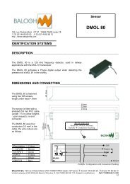
3.0 Electrical Specifications:BIDN15 mm5 mm1.5 mm3.1 Network Power Requirements:Voltage:24VDCTolerance:+/- 1% DCLine Regulation:0.3% maxLoad Regulation:0.3% maxTemperature Coefficient: 0.03% per deg C maxInput Frequency Range: 48-62 Hz minimumOutput Ripple:250 mV p-p• Please reference Appendix F DeviceNet ® Power Specifications (Volume 1) for more complete data.3.2 BIDN Power Requirements (from the Network source):The BIDN uses the network power supply to power the unit and Transceivers. The network power supplymust meet the requirements outlined within the DeviceNet ® power specification. The total current draw fromall DeviceNet ® units on a Bus must not exceed that of the network power supply.Voltage:24VDCTolerance:+/- 1% DCMaximum Current Consumed: 70mA + Transceiver connection @ 24VDCBALOGH SA, 189 rue d'Aubervilliers CP 97 75886 PARIS Cedex 18 FRANCE - Subject to Modifications2
BIDN Power Requirements3.3 BIDN Power Consumption (without Transceivers):Maximum current consumed 70mA @ 24VDC3.4 BIDN Power Consumption (with 2 Transceivers):Maximum current consumed 350mA @ 24VDC4.0 Hardware Description:4.1 Status LEDS:The BIDN is equipped with 9 status LEDS that are externally visible.• 1 Bicolor LED indicating the health of the device (i.e. Module Status)• 1 Bicolor LED indicating status of the communication link (i.e. Network Status)• 3 LEDS per channel indicating TAG Present (Green), Operation in Progress (Green), and Fault (Red)• 1 - 24 Volt DC LEDModule Status LEDFor this state: LED is: To indicate:No Power Off There is no power applied to the device.DeviceOperationalGreenThe device is operating in a normal condition.Device in Standby Flashing Green The device needs commissioning due to configuration missing,incomplete, or incorrect.Minor Fault Flashing Red Recoverable fault.UnrecoverableFaultRedThe device has an unrecoverable fault. Contact BALOGH.Network Status LEDFor this state: LED is: To indicate:Not Powered/Not On–Device is not on–line. The device has not completed the Dup_MAC_IDOfflinetest yet. The device may not be powered, look at Module Status LED.Device is on–line but has no connections in the established state. TheOn–line, NotFlashing device has passed the Dup_MAC_ID test, is on–line, but has noConnectedGreen established connections to other Nodes. For a Group 2 Only device itmeans that this device is not allocated to a master.Link OKOn–line, ConnectedConnection Time–OutCritical Link FailureGreenFlashingRedRedThe device is on–line and has connections in the established state.One or more I/O Connections are in the Timed–Out state.Failed communication device. The device has detected an error that hasrendered it incapable of communicating on the network.BALOGH SA, 189 rue d'Aubervilliers CP 97 75886 PARIS Cedex 18 FRANCE - Subject to Modifications3
Green Operation in ProgressFor this state:LED is: To indicate:Command in Progress On Executing CommandNo Command in Progress Off Idle: No Command PendingGreen TAG Present LEDSFor this state:LED is: To indicate:TAG Present On TAG is in the Transceiver's Transmission ZoneTAG Absent Off TAG is not within the Transceiver's Transmission ZoneRed Channel Status LEDSFor this state: LED is: To indicate:Channel detects fault On Transceiver/TAG faultChannel operational Off Transceiver/TAG is operationalNote: A Transceiver fault is indicated when the Module Status LED is blinking and either of the red ChannelStatus LEDS is on.Green Unit Power LEDSFor this state:LED is: To indicate:OnOffPower is provided to unitPower is not provided to unitThe figure below depicts the location of status LEDS on the BIDN top coverCh 1, TAG PresentCh 1, Fault.BALOGH SA, 189 rue d'Aubervilliers CP 97 75886 PARIS Cedex 18 FRANCE - Subject to Modifications4
DIP Switches4.2 DIP Switches:The BIDN is equipped with one bank of eight DIP switches, which are located under the top cover of theenclosure to the left side of the status LEDS. These DIP switches are used to assign the Node Addressand the Data Rate.Note: 0=Off, 1=On4.2.1 Node Address:The Node Address DIP switches are used to assign the Media Access Control Identifier (or MAC ID), which isan integer identification value assigned to each Node on DeviceNet ® . This value distinguishes a Node amongall other Nodes on the same link. The DIP switches are labeled NA6 through NA1, with the most significantswitch to the far left side (NA 6 = DIP SW 1 = MSB).The range of MAC ID values is from 0 to 63 (Binary). The following table illustrates the range of MAC IDsettings:NA6DIP 1NA5DIP 2NA4DIP 3NA3DIP 4NA2DIP 5NA1DIP 6NODEADDRESS0 0 0 0 0 0 000 0 0 0 0 1 010 0 0 0 1 0 02- - - - - - -- - - - - - -1 1 1 1 1 1 63BALOGH SA, 189 rue d'Aubervilliers CP 97 75886 PARIS Cedex 18 FRANCE - Subject to Modifications5
Data Rate4.2.2 Data Rate:The Data Rate DIP switches are used to assign the baud rate setting for the module. The DIP switchesare labeled DR2 and DR1, with the most significant being DR2 = DIP SW 7 = MSB. The ranges ofselectable Data Rates are 125K baud, 250K baud, and 500K baud. The table below illustrates thepossible switch settings:DR2 DR1 DATA RATE0 0 125K baud0 1 250K baud1 0 500K baud4.2.3 Example DIP Switch Settings:The following example depicts the DIP switch settings for Node Address 12 and Data Rate of 500K baud:4.2.4 TAG Addressing:TAG TypeOMA 64 byte 2048 - 2111OMA 2K byte 0 - 2044OMA 8K byte 0 - 8180Address (in bytes)OMX 8K byte 0 - 8191OMX 32K byte 0 - 32767GIE 512 byte 0 - 511GIE 2K byte 0 - 2047GIE 8K byte 8192 - 16383EE and EARead 0-47 Write 12-59 generally.Must Read or Write in blocks of (4) bytes to Tag.(Write offset equal to Read addresses)BALOGH SA, 189 rue d'Aubervilliers CP 97 75886 PARIS Cedex 18 FRANCE - Subject to Modifications6
Connections4.3 Connections:All connections to the BIDN are made through three quick connectors:2- 5 pin female connectors for Transceiver connections1- 5 pin male DeviceNet ® specific sealed mini-style connector to attach to the networkBIDN Connectors Bottom View:®4.3.1 Connection Pinouts and Mating Types:4.3.1.1 Transceiver Connection Pinouts and Mating Types:The following table lists the connector types that are specified for connecting a Transceiver to the BIDNModule. Please consult the appended data sheet for complete details.BALOGH SA, 189 rue d'Aubervilliers CP 97 75886 PARIS Cedex 18 FRANCE - Subject to Modifications7
Terminating the Network4.4 Terminating The Network:4.4.1 Terminating Resistors:DeviceNet ® requires a terminating resistor to be installed at each end of the trunk. The resistorrequirements are: · 121 Ohms1% Metal Film1/4 WattImportant:Terminating resistors should never be included in Nodes. Inclusion of this capability could easily lead to anetwork with improper termination (too high or too low an impedance), potentially causing failure. Forexample, removal of a Node that includes a terminating resistor could result in network failure.Terminating resistors should not be installed at the end of a drop line, only at the two ends of the trunkline.BALOGH SA, 189 rue d'Aubervilliers CP 97 75886 PARIS Cedex 18 FRANCE - Subject to Modifications8
BIDN "OF" Read-Only TAGUsing Bitstrobe I/OBALOGH SA189, rue d'AbervilliersCP97 75886 Paris Cedex 18Tel: 33 1 44 65 65 00BALOGH SA, 189 rue d'Aubervilliers CP 97 75886 PARIS Cedex 18 FRANCE - Subject to Modifications9
BALOGH SA, 189 rue d'Aubervilliers CP 97 75886 PARIS Cedex 18 FRANCE - Subject to Modifications10
Communications Description5.0 Communications Description:The BIDN Slave Module uses the Bit-Strobe Command/Response messages to communicate its data tothe Master. The Bit-Strobe Command and Response messages allow for the rapid movement of smallamounts of I/O data between a Master and its Bit-Strobed Slaves. The Bit-Strobe Command sends one bitof output data to each BIDN whose MAC ID appears in the Master’s scan list. The Bit-Strobe Commandmessage contains a bit string of 64 bits (8 bytes) of output data, one output bit per MAC ID on the network.One bit is assigned to each MAC ID supported on the network (0-63). Each BIDN uses this one bit of inputdata as a trigger to produce an 8 byte response. This response contains the last available ChannelStatus and TAG Read data as it relates to each Transceiver channel. The figure below depicts theassociation between the Masters Bit-Strobe request and the BIDN response.MAC ID = 9SlaveBIDNMAC ID = 11SlaveBIDNMAC ID = 12SlaveBIDNMAC ID = 13SlaveBIDNMAC ID = 62SlaveBIDN5.1 Contents of the Bit Strobe Response Packet:The Bit-Strobe Response packet produced by the BIDN contains 8 bytes of data. This packet is divided intotwo zones of information: one zone containing 4 bytes of Channel Status and Read data for Channel 1 andthe other 4 bytes with the same data relating to Channel 2. The BIDN automatically manages the readingof the TAG each time a new TAG arrives in the zone of the Transceiver. The only programming requiredby the user is to map the one bit of consumed input data required to trigger the response to the BIDN.10100000 10100000 10100000 10100000 10100000 10100000 10100000 10100000BALOGH SA, 189 rue d'Aubervilliers CP 97 75886 PARIS Cedex 18 FRANCE - Subject to Modifications11
Description of the Status Byte5.2 Description of the Status Byte:The Status Byte contains information that relates to the state of the Read operation at each Transceiverchannel. The information in the Status Byte can be applied to the users ladder logic to indicate when aRead has occurred or when an error has been detected. The table below breaks down the bitwise meaningof the Status Byte.Read Status Byte DefinedBit 7 Bit 6 Bit 5 Bit 4 Bit 3 to 0OperationStatus BitNot UsedTAG PresentGeneralFaultSpecific Fault5.2.1 Definition of the Status Bits:Operational Status BitState of BitHighLowMeaning:TAG Read operation is complete.TAG Read operation is in progress.TAG Present BitState of BitHighLowMeaning:TAG is present in the Transmission Zone of the Transceiver.TAG is not present within the Transmission Zone of the Transceiver.General Fault BitState of BitHighLowMeaning:Error has been detected Reading the TAG or at the Transceiver.Read operation was successful, no errors detected.BALOGH SA, 189 rue d'Aubervilliers CP 97 75886 PARIS Cedex 18 FRANCE - Subject to Modifications12
BALOGH Status Byte:MSBLSB7 6 5 4 3 2 1 0Error Error Error ErrorEXE Bit Low Battery TAG Pre Error BitCode Code Code CodeBit 7) EXE Bit = Command Execution Status (1=Command Complete) (0=Command In Progress)Bit 6) Low Batt = (0=Battery OK) (1=Low Battery)Bit 5) TAG Pre = TAG Presence (0=No TAG Present) (1=TAG Present)Bit 4) Error Bit = (0=No Error) (1=Error, See Error Code)Bits 3,2,1,0) Error Code :0001 = Invalid Request Parameters0010 = PIC Watchdog Error (internal circuitry)0011 = Internal circuitry Error0101 = PIC Dialogue Error (internal circuitry)1100 = Transceiver Error or Link Error1110 = Battery-operated Tag not initialized1111 = Impossible to complete the dialogue1011 = OMA Address Error5.3 Description of TAG Read Data:For the purposes of providing a quick and simple Fixed Code interface to the DeviceNet ® network, only2 bytes of data are read from the BALOGH "OF" Style 7 byte Fixed Code TAG, from the 7 bytes availableon the TAG. This provides a range of numbers from 0 to 65535. By utilizing the Data Table Bit Mappingfeatures provided in the DeviceNet ® manager software, only the bits of information required for theapplication need to be mapped into the Input Image Data File of the PLC.Segment of Tags Memory map readOF- Style TagTag Address 0 MSB15 14 13 12 11 10 09 08Tag Address 1 LSB07 06 05 04 03 02 01 00BALOGH SA, 189 rue d'Aubervilliers CP 97 75886 PARIS Cedex 18 FRANCE - Subject to Modifications13
Mapping the BIDN/FF to the DeviceNet ®6.0 Mapping the BIDN/FF to the DeviceNet ® :The following discussion will outline one method used to map a BIDN/FF Module onto the DeviceNet ®Network. This should be considered an example only. Other software resources may be available toConfigure a network. We will not attempt, nor will we be held responsible for the testing, verification, &support of methods not known at the time of this publication.6.1 Connection to the Network:6.1.1 Going Online:Once the physical link requirements of the network have been met (i.e. proper cabling & terminationresistors), the BIDN/FF Bit-Strobe response data must be mapped into the 1747-SDN Scanner Module’sInput Image File. The first step required is to establish an online connection with the network usingthe Allen-Bradley 1770-KFD Module hardware and the RSNetWorx Software. Start by clicking onthe RSNetWorx icon on the desktop to launch the application.BALOGH SA, 189 rue d'Aubervilliers CP 97 75886 PARIS Cedex 18 FRANCE - Subject to Modifications14
6.1.2 RSNetWorx for DeviceNet:Once you launch the application do a full network scan. The BIDN device should be picked up in the networkscan. Make sure the node address of the device is the same one that was set up for the BIDN. Once the scan iscomplete click on the unrecognized device icon and click yes to launch the EDS Wizard.BALOGH SA, 189 rue d'Aubervilliers CP 97 75886 PARIS Cedex 18 FRANCE - Subject to Modifications15
Loading The EDS File6.2 Loading the EDS File:Once the EDS Wizard is launched you need to load our supplied EDS file. You can find the EDS file onour website at www.balogh-group.com..Once the EDS file is loaded make sure the BALOGH configuration is right. The I/O map should be 8 Bytesinput and 1 Byte output..BALOGH SA, 189 rue d'Aubervilliers CP 97 75886 PARIS Cedex 18 FRANCE - Subject to Modifications16
Mapping Input Data6.3 Mapping Input Data:6.3.1 Opening the scan list editor:To utilize the information returned from the BIDN/FF, the data will need to be mapped into the Input ImageFile associated with the 1747-SDN Scanner Module. You start by double clicking on the scanner icon inthe RSNetWorx software. This opens up the scanners I/O options. You then need to click on the scan listtab.The scan list tab will list all devices that can be mapped in to the scanner. You just move the devices you wantmapped in over.BALOGH SA, 189 rue d'Aubervilliers CP 97 75886 PARIS Cedex 18 FRANCE - Subject to Modifications17
Configuration6.3.2 Configuration of the Data Table Map:You then can move the mapped data around the data table how ever you like with the Input and Output tabs.You can determine where each device is located in the data table. The software automatically assigns deviceslocations in the data table by default. You can then move them around how every you would like if you need tochange it.BALOGH SA, 189 rue d'Aubervilliers CP 97 75886 PARIS Cedex 18 FRANCE - Subject to Modifications18
BALOGH SA, 189 rue d'Aubervilliers CP 97 75886 PARIS Cedex 18 FRANCE - Subject to Modifications19
Application Example7.0 Application Example:The following ladder logic demonstrates one method to utilize the operation complete bit to interlock theTransfer of Read data from the Input Image File to an Integer File.When the operation complete bit has transitioned from low to high, new data is available at the Input ImageTable located in the 1747-SDN.BALOGH SA, 189 rue d'Aubervilliers CP 97 75886 PARIS Cedex 18 FRANCE - Subject to Modifications20
BIDN Read/Write TAG SeriesUsing Change of State ProtocolBALOGH SA189, rue d'AubervilliersCP97 75886 Paris Cedex 18Tel: 33 1 44 65 65 00BALOGH SA, 189 rue d'Aubervilliers CP 97 75886 PARIS Cedex 18 FRANCE - Subject to Modifications21
BALOGH SA, 189 rue d'Aubervilliers CP 97 75886 PARIS Cedex 18 FRANCE - Subject to Modifications22
BIDN with Change of State ProtocolDevice Description:The BIDN is a two channel RFID interface unit for the DeviceNet ® network. This unit allows support for theReading and Writing of all BALOGH Read/Write TAGS. The BIDN is a slave device on the DeviceNet ®network using the Acknowledged Change of State connection to move commands and data between themaster scanner and the Slave Node. The device is considered a Generic Device Type, which will produce132 bytes of TAG Read data and Channel Status, and will consume 22 bytes of instruction format and TAGWrite data. The following examples will provide specific information required to communicate to the BIDNfrom the PLC Data Files and setup a BIDN using Allen Bradley’s DeviceNet ®Manager Software Tool.8.0 Configuration Using RSNetWorx For DeviceNet:Steps Involved:In order to communicate with the BIDN, the network scanner must first be configured to recognize the I/OParameters and communication characteristics of the device. Once these parameters are entered, theDevice must be mapped into the I/O region of the scanner’s memory. After these steps are taken, this dataCan be saved in a scan list file (.sl*) and in the scanner’s flash memory.8.1 Online:With the BIDN attached to the network, scan the network using the Online Tab function.8.2 Loading the EDS file:After you click on the online tab and the scan is complete you need to click on tool then EDS Wizard. Onceyou start the EDS Wizard you will need to click on load a directory of EDS Files. You will then pick thedirectory where you have the EDS files stored. If you don’t have the EDS files you can get them atwww.balogh-group.com .(site:Modul-r.com, tab: Bibliothèque).BALOGH SA, 189 rue d'Aubervilliers CP 97 75886 PARIS Cedex 18 FRANCE - Subject to Modifications23
The BALOGH device type is Generic. The connection type is Change of State.Input size equals 132Bytes. Output size equals 22 bytes.8.3 Mapping I/O Parameters:To map in the BIDN I/O you must double click on the 1747-SDN Module. You then will need to load a scanlist to the scanner. The scanner will already no the I/O parameters for the BIDN it get the info from the EDSFile. You will only have to set up where you would like your I/O needs to be mapped in.BALOGH SA, 189 rue d'Aubervilliers CP 97 75886 PARIS Cedex 18 FRANCE - Subject to Modifications24
Edit I/O Parameters8.4 Edit I/O Parameters:This example below depicts the mapping of the 64 byte configuration. The BIDN now has several different I/Opossibilities depending on the users needs. It can be setup for 8, 16, 32, and 64 byte configurations. This optionis only available with the newest revisions of the unit and also requires a special configuration cable to change issettings. The unit default setting in 64 bytes I/O.I/O Mapping Parameters:8 BYTE I/O MAP:STATUSDATACH1 BYTE 0-1 BYTE 2 – BYTE 9 (64 BITS)CH2 BYTE 10-11 BYTE 12 – BYTE 19 (64 BITS)16 BYTE I/O MAP:STATUSDATACH1 BYTE 0-1 BYTE 2 – BYTE 17 (128 BITS)CH2 BYTE 18-19 BYTE 20 – BYTE 35 (128 BITS)32 BYTE I/O MAP:STATUSDATACH1 BYTE 0-1 BYTE 2 – BYTE 33 (256 BITS)CH2 BYTE 34-35 BYTE 36 – BYTE 67 (256 BITS)64 BYTE I/O MAP:STATUSDATACH1 BYTE 0-1 BYTE 2 – BYTE 65 (512 BITS)CH2 BYTE 66-67 BYTE 68 – BYTE 131 (512 BITS)COS 64 Byte Input Data Mapping:The first map segment maps in the first 16 bits (1 word) of the returned COS message from the BIDN. ThisIs mapped into the Input Image Table of your choice. This data contains the Channel #1 BALOGH StatusByte and the channel number.BALOGH SA, 189 rue d'Aubervilliers CP 97 75886 PARIS Cedex 18 FRANCE - Subject to Modifications25
The second map segment contains the 16 bits (1 word) of BALOGH status and channel number data forChannel #2. This information starts at byte 66 of the returned COS message from the BIDN and mappedInto the Input Image Table location of your choice.You will map the third map segment in the TAG data returned from the BIDN for Channel #1. The datawill be placed into the M1 file location of your choice. The data will start at byte 2 of the returned COSmessage from the BIDN. In this example, the whole 512 bits were mapped in.BALOGH SA, 189 rue d'Aubervilliers CP 97 75886 PARIS Cedex 18 FRANCE - Subject to Modifications26
The fourth map segment will map in the TAG data return from the BIDN for Channel #2. The data will beMapped starting at byte 68 of the COS message from the BIDN and placed in the M1 file location of yourChoice. In this example, the whole 512 bits were mapped in.COS Output Data Mapping:Map segment 1 will map the M0 file data to send to the BIDN. This is for both Channels #1 and #2. TheNumber of bits will always equal 176.You have now completed the mapping in of the BIDN into the 1747 SDN Module. Mapping of the BALOGHBIDN may vary depending on the PLC type & DeviceNet ® scanner being used. The functionality of the BIDNDoes not change.BALOGH SA, 189 rue d'Aubervilliers CP 97 75886 PARIS Cedex 18 FRANCE - Subject to Modifications27
I/O ConfigurationBIDN I/O Configuration Change:The I/O settings for the BIDN can be changed on the latest revision boards. This will require a specialconfiguration cable. This will also require a terminal program of some sort to retrieve the serial string that theBIDN will send out on power up. We will be using Hyper terminal in our screen shots.When the cable is hooked up and the BIDN is powered up it will send out a serial command like this. You willthen need to select which type of configuration you would like.1 = 64 Byte I/O (Default)2 = 32 Byte I/O3 = 16 Byte I/O4 = 8 Byte I/OCOMM settings:Data Rate 19200Data bits 8Parity NoneStop bits 1Flow control NoneBALOGH SA, 189 rue d'Aubervilliers CP 97 75886 PARIS Cedex 18 FRANCE - Subject to Modifications28
Once you select which option you would like it will tell you which one you have selected.The BIDN will then need to be power cycled for the settings to take effect.You will then need to do a new hardware scan in RSNetWorx to map in the new I/O parameters.When you do the new scan RSNetworxs will load the appropriate EDS fie for the unit.BALOGH SA, 189 rue d'Aubervilliers CP 97 75886 PARIS Cedex 18 FRANCE - Subject to Modifications29
Command Structure9.0 Command Structure:The BIDN will consume 22 bytes of TX data and will produce 132 bytes of Rx data. This information will beComprised of commands and data as input information to the BIDN and channel, status and data as outputInformation from the BIDN.9.1 Read/Write Request:To execute a Read or Write command from the PLC to the BIDN, the output data fields should be organizedIn memory according to the format defined below. Each field represents one byte of information. Two fieldsWill equal one word in the PLC integer file.Request organization within a PLC file.CHANNELINSTRUCTION 00 LENGTH HIGH ADDR. LOW ADDR. DATA HIGH DATA LOWWORD 0 WORD 1 WORD 2 WORD 3Instruction FieldCommand Command Code MeaningClears Scanner output file.IDLE00hDisabling duplicate commands from being sent.Read a current TAG with no wait. To do a Read w/ Wait,READ01hTransition bit 14 in the High Address byte high. A TAG does not needto be present when issuing a Read command w/ Wait.WRITE02hWrites a current TAG with no wait. To do a Write w/Wait, Transitionbit 14 in the High Address byte high. A TAG does not need to bepresent when issuing a Write command w/ Wait.RESET 04h Resets both Transceiver channels.SET 08h Sets a range of TAG memory to a specific value.DELAY 10h Establishes a delay in the toggling of the execution bit.Channel FieldChannel Command Code MeaningChannel 1 01h Direct request to Channel 1.Channel 2 02h Direct request to Channel 2.Read/Write with Wait:High Byte of TAG Address Field15 14 13 12 11 10 9 8Not With waitUsed StateNot Used Address Address Address Address AddressBit 15: Not UsedBit 14: Low=No Wait, High=With WaitBit 13: Not UsedBit 8-12: High Byte of TAG AddressBALOGH SA, 189 rue d'Aubervilliers CP 97 75886 PARIS Cedex 18 FRANCE - Subject to Modifications30
Example of Delay Command:The delay command is used when the transition of the BALOGH execution bit happens too fast for the usersLogic to sense.Channel #Extra Delay Time10h 00Not Used Not Used Not Used Not Used01or 02 h(00-FFh)WORD 0 WORD 1 WORD 2 WORD 3Note:The delay command must be sent after the unit is communicating and will need to be sent again if thePower to the unit or the Bus is cycled. It does not matter if the command is sent to Channel #1 or Channel#2. Once the delay is enabled, it will have the same effect for both channels. Adding this artificial delay willAffect length of communication time. Each increment (00 to FFh) adds 1ms delay.Length FieldHigh Byte is always 00hLow Byte Range 01h to 3EhAddress FieldHigh Byte Range00h to 1FhLow Byte Range00h to FFhNote: Maximum addressable byte = 1FFDh.Data FieldHigh Byte Range00h to FFhLow Byte Range00H to FFh9.2 Read/Write Response:The response data field is split into two separate fields that contain the contents of Channel #1 and Channel#2. The response contains 2 bytes of channel information and 64 bytes of either TAG data (in the event ofA Read operation) or the echo of the data field (that was written in the event of Write operation).Response strings organizationSTATUS CH1CHANNEL 1 DATA HIGH DATA LOW STATUS CH 2 CHANNEL 2 DATA HIGH DATA LOWWORD 0 WORD 1 TO 32 WORD 33 WORD 34 TO 66Response data field 1 Response data field 2BALOGH SA, 189 rue d'Aubervilliers CP 97 75886 PARIS Cedex 18 FRANCE - Subject to Modifications31
Status Byte10.0 Description of the Status Byte:The Status Byte contains information that relates to the state of the Read/Write operation at eachTransceiver channel. The information in the Status Byte can be applied to the user’s ladder logic toindicate when a Read has occurred or when an error has been detected. The table below breaks downthe bit wise meaning of the Status Byte.10.1 Definition of the Status Bits:Execution BitState of BitHighLowMeaning:TAG Read operation is complete.TAG Read operation is in progress.Low Battery BitState of BitHighLowMeaning:TAG battery is low.TAG battery is OK.TAG Present BitState of BitHighLowMeaning:TAG is present within the Transmission Zone of the Transceiver.TAG is not present within the Transmission Zone of the Transceiver.General Fault BitState of BitHighLowMeaning:Error has been detected Reading the TAG or at the Transceiver.Read operation was successful; no errors detected.BALOGH SA, 189 rue d'Aubervilliers CP 97 75886 PARIS Cedex 18 FRANCE - Subject to Modifications32
10.2 Description of TAG Memory Organization and the PLC Memory Data Format:Bit 7 Bit 6 Bit 5 Bit 4 Bits 3 to 0ExecutionBitLowBatteryTAG TagPresentGeneralFaultSpecificFaultTag Memory LayoutPLC N:XX File OrganizationMSB LSB MSB LSB MSB LSBByte 1 Byte 0 Byte 3 Byte 2 Byte 5 Byte 4Word 0 Word 1 Word 2BALOGH Status Byte:MSBLSB7 6 5 4 3 2 1 0Error Error Error ErrorEXE Bit Low Battery TAG Pre Error BitCode Code Code CodeBit 7) EXE Bit = Command Execution Status (1=Command Complete) (0=Command In Progress)Bit 6) Low Batt = (0=Battery OK) (1=Low Battery)Bit 5) TAG Pre = TAG Presence (0=No TAG Present) (1=TAG Present)Bit 4) Error Bit = (0=No Error) (1=Error, See Error Code)Bits 3,2,1,0) Error Code :0001 = Invalid Request Parameters0010 = Watchdog Error (internal circuitry)0011 = Internal circuitry Error0101 = Dialogue Error (internal circuitry)1100 = Transceiver Error or link Error1110 = Battery-operated Tag not initialized1111 = Impossible to complete the Tag Dialogue1011 = OMA Address ErrorBALOGH SA, 189 rue d'Aubervilliers CP 97 75886 PARIS Cedex 18 FRANCE - Subject to Modifications33
BALOGH SA, 189 rue d'Aubervilliers CP 97 75886 PARIS Cedex 18 FRANCE - Subject to Modifications34
BIDN Communications Using aDeviceNet ® PC Card withChange of State Protocol,and Bit Strobe I/OBALOGH SA189, rue d'AubervilliersCP97 75886 Paris Cedex 18Tel: 33 1 44 65 65 00BALOGH SA, 189 rue d'Aubervilliers CP 97 75886 PARIS Cedex 18 FRANCE - Subject to Modifications35
BALOGH SA, 189 rue d'Aubervilliers CP 97 75886 PARIS Cedex 18 FRANCE - Subject to Modifications36
Communication Procedures11.0 Communication procedures for the BIDN and DeviceNet ® PC Card in Change of StateMode:Using the predefined Master/Slave connection set, this section provides the commands needed tocommunicate to the BALOGH BIDN when using a DeviceNet ® compliant Change of State PC card.11.1 Communicating with the BIDN DeviceNet ® Interface:(Complete the following steps in order)1. Open the explicit messaging & COS (Change Of State) connectionsAllocate_Master/Slave_Connection_Set ServiceService Code Class ID Instance ID Allocation Choice Allocators MACIDMaster MACID 4B 3 1 51 Master MACIDExplicit + CO With Acknowledge SuppressionMessage Length = 6 bytesThe BIDN initiates connection instances 1 (Explicit), 2 (Poll), & 4 (COS):The Explicit connection is used to transmit explicit requestsThe Polled connection instance is used for master to slave (BIDN) data transmissionThe COS connection instance is used for slave (BIDN) to master data transmission2. Set the value for the Expected Packet RateFor the Explicit connectionService Code Class ID Instance Attribute Value ValueMaster MACID 10 05 01 09 0 0Connection Class ID, Expected packet rate default value 0 (no expected packet rate)3. Set Production Inhibit TimerMaster MACID 10 05 04 11 0 04. Set Polled Expected Packet RateMaster MACID 10 05 02 09 0 05. Set Change of State Expected Packet RateMaster MACID 10 05 04 09 0 0If the user has cyclic message transmissions on this connection, you must determine the TransmissionRate and set a value different than 0. Message length = 7 bytes.For the COS connection, the default value is 0. Since the Transmission Rate is not predictable, BALOGHsuggests not to modify this value.BALOGH SA, 189 rue d'Aubervilliers CP 97 75886 PARIS Cedex 18 FRANCE - Subject to Modifications37
11.2 Send/Receive Commands, Data & Status:Command Request Codes:Code Command Description0 Idle Message (no request) When this command is sent, the BIDN responds with updated status1 TAG Read Reading data from a TAG, up to 64 bytes max. per command2 TAG Write Writing data to a TAG, up to 16 bytes max. per command4 Reset Resets the selected channel to an idle state8 TAG Fill Sets a specified value to a range on the TAG16 Delay Sets a delay (up to 255 ms) from the BIDN sending the results of aRead/Write command to the MasterCommand Request Packet:The Master uses the Polled connection instance.Request Code Channel #(nr) Number of bytes (lenl) 0 address L address H data 1 data 2 data nChannel # (nr): (1) for Transceiver 1, (2) for Transceiver 2Number of Bytes (lenl): Least significant byte of number of bytes to Read/WriteAddress Low (addl): Least significant byte of TAG addressAddress High (addh): Most significant byte of TAG addressIn the appendix section of this manual, there are flowcharts for both Reading and Writing, using Change ofState protocol. These charts diagram what will occur when a TAG enters the Transceiver zone andwhen a command is sent. The data packet length sent by the Master to the BIDN will total 22 bytes: 6byte header and 16 bytes of data. The amount of data that can be written to a TAG with one commandvaries from 1 byte to 16 bytes of data.Receive Data Packet from Slave (BIDN):The data packet sent by the BIDN is on the connection instance 4 (COS). The packet size will total 151bytes (includes DeviceNet ® protocol headers). Of these, there are 132 bytes of data (both channels of theBIDN): 4 bytes of Channel Status and 128 bytes of Read data. This packet is returned to the Master fromthe BIDN (slave) every time there is a Change of State. Examples of a Change of State would be if a TAGenters the Transceiver zone (TAG presence goes High) or a command is sent to the BIDN and is differentfrom the last command sent. When a BIDN receives an idle command, it will always send updated statusfor both channelsData Packet from BIDN:Channel 1 Status data 1 data 2 ..... data n Channel 2 Status data 1 data 2 .... data nBALOGH SA, 189 rue d'Aubervilliers CP 97 75886 PARIS Cedex 18 FRANCE - Subject to Modifications38
Description of the BALOGH Status Byte:MSBLSB7 6 5 4 3 2 1 0Error Error Error ErrorEXE Bit Low Battery TAG Pre Error BitCode Code Code CodeBit 7) EXE Bit = Command Execution Status (1=Command Complete) (0=Command In Progress)Bit 6) Low Batt = (0=Battery OK) (1=Low Battery)Bit 5) TAG Pre = TAG Presence (0=No TAG Present) (1=TAG Present)Bit 4) Error Bit = (0=No Error) (1=Error, See Error Code)Bits 3,2,1,0) Error Code :0001 = Invalid Length Error0010 = Watchdog Error (internal circuitry )0011 = Internal circuitry Error0101 = Dialogue Error (internal circuitry)1100 = Transceiver Error or Link Error1110 = Battery-operated Tag not initialized1111 = Impossible to complete the Tag Dialogue1011 = OMA tag Address Error11.3 Closing the Explicit Messaging & COS Connections:Before exiting the application, the Master should release the allocated connections. This is done by thefollowing:Release_Master/Slave_Connection_Set Service:Service Code Class ID Instance ID Release ChoiceMaster MACID 4C 3 1 11Explicit + COSMessage Length = 5 bytesBALOGH SA, 189 rue d'Aubervilliers CP 97 75886 PARIS Cedex 18 FRANCE - Subject to Modifications39
12.0 Communication Procedures for the BIDN/FF DeviceNet ® PC Card using Bit Strobe I/OMode: This section provides the commands needed to communicate to the BALOGH BIDN/FF whenusing a DeviceNet ® compliant PC Card.12.1 Communication with the BIDN DeviceNet ® Interface:(Complete the following steps in order)1. Open the explicit messaging & Bit Strobe I/O connections:Allocate_Master/Slave_Connection_Set Service:Service Code Class ID Instance ID Allocation Choice Allocators MAC IDMaster MACID 4B 3 1 05 Master MAC IDExplicit + Bit Strobe I/OMessage Length = 6 bytesThe BIDN initiates connection instances 1 (Explicit), 2 (Poll), & 4 (COS):The Explicit connection is used to transmit explicit requestsThe Polled connection instance is used for master to slave (BIDN) data transmissionThe COS connection instance is used for slave (BIDN) to master data transmission2. Set the value for the Expected Packet Rate For the Explicit connection:Service Code Class ID Instance Attribute Value ValueMaster MACID 10 05 01 09 0 0Connection Class ID Expected packet default value 0 (no expected packet rate) Rate12.2 Communication Packet Returned from BIDN/FF to the Host:The BIDN/FF returns 8 bytes of strobe input data. When an OF Read-Only TAG enters the Transceiverzone, the data is read by the BIDN/FF and sent back to the Host. No Read command needs to be sentto the BIDN/FF. As long as the OF TAG remains in the Transceiver zone, the BIDN/FF will continue tosend the TAG data back to the Host. When the OF TAG leaves the Transceiver zone and the BIDNreceives the I/O trigger from the Host, the BIDN will respond with updated status for both channels. In theappendix section of this manual, there is a flowchart diagramming this communications process.8 Byte Bit-Strobe Data Packet from BIDN/FF:Byte 0 Byte 1 Byte 2 Byte 3 Byte 4 Byte 5 Byte 6 Byte 7TAG TAGTAG TAGChannel AlwaysChannel 2 AlwaysAddress 1 Address 0Address 1 Address 01 Status 00 HexStatus 00 HexChannel 1 Channel 1Channel 2 Channel 2BALOGH SA, 189 rue d'Aubervilliers CP 97 75886 PARIS Cedex 18 FRANCE - Subject to Modifications40
Description of the BALOGH Status Byte:MSBLSB7 6 5 4 3 2 1 0Error Error Error ErrorEXE Bit Low Battery TAG Pre Error BitCode Code Code CodeBit 7) EXE Bit = Command Execution Status (1=Command Complete) (0=Command In Progress)Bit 6) Low Batt = (0=Battery OK) (1=Low Battery)Bit 5) TAG Pre = TAG Presence (0=No TAG Present) (1=TAG Present)Bit 4) Error Bit = (0=No Error) (1=Error, See Error Code)Bits 3,2,1,0) Error Code :0001 = Invalid Request Parameter0010 = Watchdog Error (internal circuitry)0011 = Internal circuitry Error0101 = Dialogue Error (internal circuitry)1100 = Transceiver Error or Link Error1110 = Battery-operated Tag not initialized1111 = Impossible to complete the Tag Dialogue1011 = OMA tag Address Error12.3 Closing the Explicit Messaging:Before exiting the application, the Master should release the allocated connections. This is done by thefollowing:Release_Master/Slave_Connection_Set Service:Service Code Class ID Instance ID Release ChoiceMaster MACID 4C 3 1 11Explicit + COSMessage Length = 5 bytes.BALOGH SA, 189 rue d'Aubervilliers CP 97 75886 PARIS Cedex 18 FRANCE - Subject to Modifications41
BALOGH SA, 189 rue d'Aubervilliers CP 97 75886 PARIS Cedex 18 FRANCE - Subject to Modifications42
APPENDIXBIDN CommunicationsFlowchartsBALOGH SA189, rue d'AubervilliersCP97 75886 Paris Cedex 18Tel: 33 1 44 65 65 00BALOGH SA, 189 rue d'Aubervilliers CP 97 75886 PARIS Cedex 18 FRANCE - Subject to Modifications43
BALOGH SA, 189 rue d'Aubervilliers CP 97 75886 PARIS Cedex 18 FRANCE - Subject to Modifications44
BIDN OF READ-ONLY TAG FlowchartScanner (Master)BIDN (Slave)StartSends I/OtriggerReceives trigger &sends statusUpdatesstatusOF series TAGenters Transceiverzone and is Read byBIDN.Sends I/OtriggerBIDN sets bit 7 ofstatus low to startRead, then highwhen it completesRead and sendsdata.Receives datafrom BIDNError ?Checkbit 4 ofstatusIf a TAG remains inthe Transceiverzone, and thescanner sends theI/O trigger after theTAG is Read, theBIDN will re-sendthe data. Once theTAG leaves thezone, the next I/Otrigger will updatethe status.Read completeBALOGH SA, 189 rue d'Aubervilliers CP 97 75886 PARIS Cedex 18 FRANCE - Subject to Modifications45
BIDN Change of State READ COMMAND FlowchartScanner (Master)BIDN (Slave)StartSends idle commandReceives idle command& sends statusReceives updated statusRead/Write TAG EntersTransceiver zoneHeartbeat Timer will sendlast command in scanner ifthere is no Bus activity tounit.Because there is aChange of State fromthe TAG, the BIDNautomatically sendsupdated status.Receives status from BIDNSend Read commandReceives updated status.Look at bit 7 of status to seetransition of bit from high tolow. Command in progress.Receives Readcommand, dropsexecution of bit from 1to 0 and sends updatedstatus.Clear command fromScanner Buffer by sendingidle.Completes Readcommand, setsexecution bit from 0 to 1and sends Read data.Receives Data with UpdatedStatus. Look at bit 7 of Status tosee transition from low to highCommand Complete.If YesError?Check bit 4of statusIf NoRead completeBALOGH SA, 189 rue d'Aubervilliers CP 97 75886 PARIS Cedex 18 FRANCE - Subject to Modifications46
BIDN Change of State WRITE COMMAND FlowchartScanner (Master)BIDN (Slave)StartSends idle commandReceives idle command& sends statusReceives updated statusRead/Write TAG entersTransceiver zoneHeartbeat Timer will sendlast command in scanner ifthere is no Bus activity tounit.Receives status from BIDNSend Write commandReceives updated status. Lookat bit 7 of status to seetransition of bit from high to low.Command in progress.Clear command fromScanner Buffer by sendingidle.Because there is aChange of State fromthe TAG, the BIDNautomatically sendsupdated status.Receives Writecommand, dropsexecution bit from 1 to 0and sends updatedstatus.Completes Writecommand. Sets executionbit from 0 to 1.Receives updated status.Look at bit 7 of status to seetransition from Low to High.Command complete.If YesError?Check bit4 of statusIf NoWrite completeBALOGH SA, 189 rue d'Aubervilliers CP 97 75886 PARIS Cedex 18 FRANCE - Subject to Modifications47
BALOGH SA, 189 rue d'Aubervilliers CP 97 75886 PARIS Cedex 18 FRANCE - Subject to Modifications48
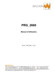
Identification - CodingDeviceNet ®Control BoardBIDN/**Reference: BIDN/** A= OMA 64, 2K, or 8K bytes Read/Write TAGP= OP 64 byte & 96 byte Read/Write TAGX= OMX High Speed 8K & 32K byte Read/Write TAGE= GIE 512, 2K, 8K byte Read/Write TAGI= OIR First 8K of 64K Read/Write TAGF= OF or OFR 7 bytes Read-Only TAGL= OL or OLR 2 byte Read-Only Extended Range TAGCharacteristics• The BALOGH BIDN meets the needs required for today's network flexibility. It is also compatible withexisting network devices such as I/O, push button, motion controls, motor starters, photo cells, limitswitches, etc.• Multi-Drop capability: Allows a connection scheme of multiple BIDN interface units on a DeviceNet ®network. Each BIDN has dual channel capability. Two Transceivers can be connected to each BIDN.Each functions independently and simultaneously.• Small footprint provides ease of mounting (150mm x 130mm x 45mm). With an IP-65 rated metallicenclosure and quick connect wiring, it provides field mounting, durability, and reduces wiring costs.• Automatic self-test upon power-up.• Selectable data transfer rates of 125K baud, 250K baud or 500K baud, and Node Addressing from 0-63.• LED indication for network and Module Status, TAG presence, and Transceiver error:2 Bicolor LEDS:4 Green LEDS:Indicating network and card statusFor system identification of Channels 1 and 2, TAG presence and operation inprogress.For system identification of the Transceiver faults24 VDC power2 Red LEDS:1 Green LED:Switch settings to define: 2 bit baud rate, switches 7 and 86 bit MAC ID Bus addresses; switches 1 thru 6Characteristics Symbol Unit BIDPSupply Power (± 1%) Ucc V 24 VDC (ripple
DeviceNet ®Control BoardBIDN/**Identification - CodingDimensionsBIDN15 mm5 mm1.5 mmConnectionsCh 1, FaultBi-Color LED Module StatusBALOGH SA, 189 rue d'Aubervilliers CP 97 75886 PARIS Cedex 18 FRANCE - Subject to Modifications50
BIDNDeviceNet ® InterfaceModifying Input LengthsVendor ID 133BALOGH189, rue d’AubervilliersCP97 75886 Paris cedex 18Tel: 33 1 44 65 65 00Notes are used to call attention to information that is significant to the understanding and operation of equipment.This BALOGH manual is based on information available at the time of its publication. We have attempted to provide accurate and up-to-dateinformation. This document does not purport to cover all details or variations in hardware or software; nor does it provide for every possiblecombination of products. Some features described herein may not be available on all like products. BALOGH assumes no obligation to notifyholders of this document of any subsequent changes. For the latest up-to-date information and specifications on BALOGH products, contactthe BALOGH web site at: http://www.balogh-group.comBALOGH makes no representation or warranty, expressed, implied or statutory with respect to, and assumes no responsibility for theaccuracy, completeness, or usefulness of the information contained in this manual. No warranties of merchantability or fitness for purposeshall apply. DeviceNet ® is a registered trademark of ODVA (Open DeviceNet ® Vendors Assoc.).Revision: November 04, 2002© Copyright BALOGH 2000BALOGH SA 189, rue d’Aubervilliers CP97 75886 Paris Cedex 18 FRANCE - Subject to Modifications
Edit Input Sizes1.0 Edit Input Sizes:The default Input / Output connection size for the BIDN is comprised of 132 bytes of Input dataand 22 bytes of Output data. In order to allow a greater number of BIDN devices to be mappedinto a scanners memory a user selectable Input image size was added as a feature to laterversions of the BIDN. This option is only available on units date coded 03205XXXX andhigher. The table below details the channel status and data offsets as they relate to the fourdifferent Input configuration sizes.8 BYTE Input MAP:STATUSDATACH1 BYTE 0-1 BYTE 2 – BYTE 9 (64 BITS)CH2 BYTE 10-11 BYTE 12 – BYTE 19 (64 BITS)16 BYTE Input MAP:STATUSCH1 BYTE 0-1CH2 BYTE 18-1932 BYTE Input MAP:STATUSCH1 BYTE 0-1CH2 BYTE 34-3564 BYTE Input MAP:STATUSCH1 BYTE 0-1CH2 BYTE 66-67DATABYTE 2 – BYTE 17 (128 BITS)BYTE 20 – BYTE 35 (128 BITS)DATABYTE 2 – BYTE 33 (256 BITS)BYTE 36 – BYTE 67 (256 BITS)DATABYTE 2 – BYTE 65 (512 BITS)BYTE 68 – BYTE 131 (512 BITS)BALOGH SA 189, rue d’Aubervilliers CP97 75886 Paris Cedex 18 FRANCE - Subject to Modifications
Edit Input Sizes1.1 BIDN Input Size Reconfiguration:This section applies only to BIDN DeviceNet interfaces manufactured after the production dateof 03205XXXX and that are capable of Reading and Writing data to the RFID Tag using theChange of State communications method. This would include units ending with a suffix suchas AA, EE, XX, PP, II, RR etc…The production date is ink jetted in the upper right had corner on the enclosures face. If thereis a question regarding a modules ability to support this method or the date code is unclearlook for the following clue.Upon power up BIDN units that support Input Size reconfiguration will pause for at least 5seconds, illuminating only the 24VDC Power Indication LED. Once the delay has expired theinitialization self test will begin by illuminating each individual LED from right to left. The 5second pause prior to initialization self test is the indication that this device supports Input Sizereconfiguration.To reconfigure the Input Size a serial communications cable will have to be assembled. Seethe section titled Flash Port Cable Assembly for instructions on building this cable. Thisprocedure will also require a terminal program to display the serial string prompts that theBIDN will send out upon power up. This example uses hyper terminal with communicationsetting of 19200 Baud , 8 Data Bits , No Parity and 1 Stop Bit.Attach the flash port cable to the BIDN-80:The flash loader port on the BIDN-80 can be found beneath the LED cover on the front of theunit. The flash port is located on the far right corner of the PCB board and is a four-positionmale .100” straight header. Pin one of the flash port is located next to the first LED(green 24 VDC power LED) towards the inside of the board and is marked with silk screenedlettering J2 1. Attach the flash loader cables four position female header to the flash port. Pinone of the cable is indicated by an arrow symbol ∆ and / or the number 1. Connect the nine pinfemale connector to the PC running your terminal software.BALOGH SA 189, rue d’Aubervilliers CP97 75886 Paris Cedex 18 FRANCE - Subject to Modifications
Edit Input SizesAfter the cable is connected apply power to the BIDN. Once power is applied a serial stringwill be sent to the display device. The screen capture below depicts the prompt on the screen.Type in any key within 5 seconds to enter Input Reconfiguration Mode.BALOGH SA 189, rue d’Aubervilliers CP97 75886 Paris Cedex 18 FRANCE - Subject to Modifications
Edit Input SizesThe BIDN will confirm that it has entered Input Reconfiguration Mode by displaying the prompt“Type the new conf value (1,2,3,4) “ the device will accept 1 of 4 possible Input configurationchoices and will wait indefinably for a selection. Enter a selection value then hit the return key.If power is lost at this phase of the operation the BIDN will use the previous setting stored inflash memory.Selection Options:Selection Configuration1 64 Bytes of Input Data / Channel2 32 Bytes of Input Data / Channel3 16 Bytes of Input Data / Channel4 4 Bytes of Input Data / ChannelBALOGH SA 189, rue d’Aubervilliers CP97 75886 Paris Cedex 18 FRANCE - Subject to Modifications
Edit Input SizesThe BIDN will save the new configuration into its flash memory and prompt the user with areminder that a different EDS file will be required. The new values will take effect after theBIDN has completed its initialization sequence.BALOGH SA 189, rue d’Aubervilliers CP97 75886 Paris Cedex 18 FRANCE - Subject to Modifications
Flash Port Cable Assembly2.0 Assembling a Flash Loader Cable:The flash loader port is a four pin RS-232 connection. The pin locations are defined in the tablebelow.Header PIN DescriptionNumber1 RS-232 Transmit2 RS-232 Receive3 RS-232 Signal Ground4 Not ConnectedThe Flash loader port is located beneath the LED face plate on the front of the BIDN-80. It is afour position male .100 straight header mounted on the far right corner of the BIDN-80 mainboard. Pin one is the pin nearest the green surface mount LED and is indicated by the silkscreen label J2-1.To assemble a cable to connect the four pin male .100” header to a nine position D-Subconnector use the following wiring guide.Header PIN Number Connection on nine pin femaleD-Sub connector1 Pin 2 RS-232 Receive data2 Pin 3 RS-232 Transmit data3 Pin 5 RS-232 Signal Ground4 Not ConnectedParts used in cable assembly are listed below.Molex connector housing 4 position C-Grid “A” series # 50-57-9004Molex crimp terminal gold female C-Grid # 16-02-0103Radio Shack 9-Position D-Subminiature connector # 276-1538CRadio Shack shielded metalized hood # 276-15133 feet of four conductor shielded cable Belden or equivalent # 9940BALOGH SA 189, rue d’Aubervilliers CP97 75886 Paris Cedex 18 FRANCE - Subject to Modifications