Download - Electrical Business Magazine
Download - Electrical Business Magazine
Download - Electrical Business Magazine

You also want an ePaper? Increase the reach of your titles
YUMPU automatically turns print PDFs into web optimized ePapers that Google loves.
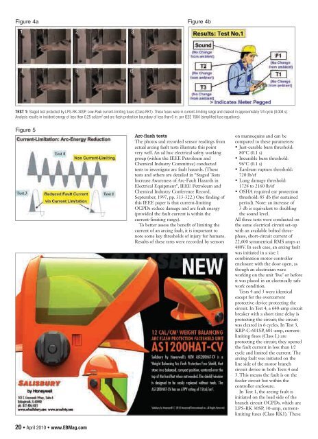
Figure 4aFigure 4bTEST 1: Staged test protected by LPS-RK-30SP, Low-Peak current-limiting fuses (Class RK1). These fuses were in current-limiting range and cleared in approximately 1⁄4 cycle (0.004 s).Analysis results in incident energy of less than 0.25 cal/cm 2 and arc flash protection boundary of less than 6 in. per IEEE 1584 (simplified fuse equations).Figure 5Salisbury_EB_April10.indd 120 • April 2010 • www.EBMag.comArc-flash testsThe photos and recorded sensor readings fromactual arcing fault tests illustrate this pointvery well. An ad hoc electrical safety workinggroup (within the IEEE Petroleum andChemical Industry Committee) conductedtests to investigate arc fault hazards. (Thesetests and others are detailed in “Staged TestsIncrease Awareness of Arc-Fault Hazards in<strong>Electrical</strong> Equipment”, IEEE Petroleum andChemical Industry Conference Record,September, 1997, pp. 313-322.) One finding ofthis IEEE paper is that current-limitingOCPDs reduce damage and arc fault energy(provided the fault current is within thecurrent-limiting range).To better assess the benefit of limiting thecurrent of an arcing fault, it is important tonote some key thresholds of injury for humans.Results of these tests were recorded by sensors3/17/10 11:39:49 AMon mannequins and can becompared to these parameters:• Just-curable burn threshold:80°C (0.1 s)• Incurable burn threshold:96°C (0.1 s)• Eardrum rupture threshold:720 lb/sf• Lung damage threshold:1728 to 2160 lb/sf• OSHA required ear protectionthreshold: 85 db (for sustainedperiod). Note: an increase of3 db is equivalent to doublingthe sound level.All three tests were conducted onthe same electrical circuit set-upwith an available bolted threephase,short-circuit current of22,600 symmetrical RMS amps at480V. In each case, an arcing faultwas initiated in a size 1combination motor controllerenclosure with the door open, asthough an electrician wereworking on the unit ‘live’ or beforeit was placed in an electrically safework condition.Tests 4 and 3 were identicalexcept for the overcurrentprotective device protecting thecircuit. In Test 4, a 640-amp circuitbreaker with a short time delay isprotecting the circuit; the circuitwas cleared in 6 cycles. In Test 3,KRP-C-601SP, 601-amp, currentlimitingfuses (Class L) areprotecting the circuit; they openedthe fault current in less than 1⁄2cycle and limited the current. Thearcing fault was initiated on theline side of the motor branchcircuit device in both Tests 4 and3. This means the fault is on thefeeder circuit but within thecontroller enclosure.In Test 1, the arcing fault isinitiated on the load side of thebranch circuit OCPDs, which areLPS-RK 30SP, 30-amp, currentlimitingfuses (Class RK1). These