RM7897A,C 7800 SERIES Relay Modules - Patriot Supply
RM7897A,C 7800 SERIES Relay Modules - Patriot Supply
RM7897A,C 7800 SERIES Relay Modules - Patriot Supply

Create successful ePaper yourself
Turn your PDF publications into a flip-book with our unique Google optimized e-Paper software.
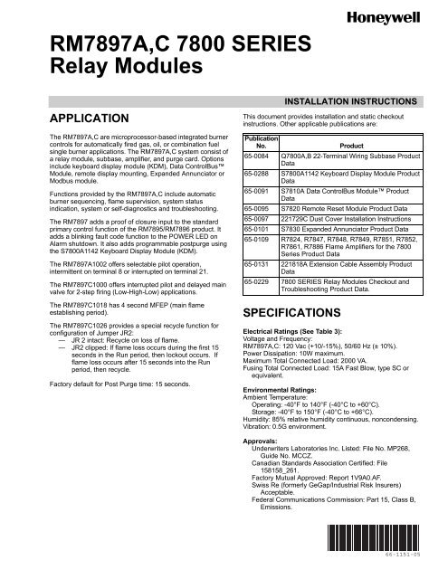
<strong>RM7897A</strong>,C <strong>7800</strong> <strong>SERIES</strong><strong>Relay</strong> <strong>Modules</strong>APPLICATIONThe <strong>RM7897A</strong>,C are microprocessor-based integrated burnercontrols for automatically fired gas, oil, or combination fuelsingle burner applications. The <strong>RM7897A</strong>,C system consist ofa relay module, subbase, amplifier, and purge card. Optionsinclude keyboard display module (KDM), Data ControlBusModule, remote display mounting, Expanded Annunciator orModbus module.Functions provided by the <strong>RM7897A</strong>,C include automaticburner sequencing, flame supervision, system statusindication, system or self-diagnostics and troubleshooting.The RM7897 adds a proof of closure input to the standardprimary control function of the RM7895/RM7896 product. Itadds a blinking fault code function to the POWER LED onAlarm shutdown. It also adds programmable postpurge usingthe S<strong>7800</strong>A1142 Keyboard Display Module (KDM).The <strong>RM7897A</strong>1002 offers selectable pilot operation,intermittent on terminal 8 or interrupted on terminal 21.The RM7897C1000 offers interrupted pilot and delayed mainvalve for 2-step firing (Low-High-Low) applications.The RM7897C1018 has 4 second MFEP (main flameestablishing period).The RM7897C1026 provides a special recycle function forconfiguration of Jumper JR2:— JR 2 intact: Recycle on loss of flame.— JR2 clipped: If flame loss occurs during the first 15seconds in the Run period, then lockout occurs. Ifflame loss occurs after 15 seconds into the Runperiod, then recycle.Factory default for Post Purge time: 15 seconds.INSTALLATION INSTRUCTIONSThis document provides installation and static checkoutinstructions. Other applicable publications are:PublicationNo.Product65-0084 Q<strong>7800</strong>A,B 22-Terminal Wiring Subbase ProductData65-0288 S<strong>7800</strong>A1142 Keyboard Display Module ProductData65-0091 S7810A Data ControlBus Module ProductData65-0095 S7820 Remote Reset Module Product Data65-0097 221729C Dust Cover Installation Instructions65-0101 S7830 Expanded Annunciator Product Data65-0109 R7824, R7847, R7848, R7849, R7851, R7852,R7861, R7886 Flame Amplifiers for the <strong>7800</strong>Series Product Data65-0131 221818A Extension Cable Assembly ProductData65-0229 <strong>7800</strong> <strong>SERIES</strong> <strong>Relay</strong> <strong>Modules</strong> Checkout andTroubleshooting Product Data.SPECIFICATIONSElectrical Ratings (See Table 3):Voltage and Frequency:<strong>RM7897A</strong>,C: 120 Vac (+10/-15%), 50/60 Hz (± 10%).Power Dissipation: 10W maximum.Maximum Total Connected Load: 2000 VA.Fusing Total Connected Load: 15A Fast Blow, type SC orequivalent.Environmental Ratings:Ambient Temperature:Operating: -40°F to 140°F (-40°C to +60°C).Storage: -40°F to 150°F (-40°C to +66°C).Humidity: 85% relative humidity continuous, noncondensing.Vibration: 0.5G environment.Approvals:Underwriters Laboratories Inc. Listed: File No. MP268,Guide No. MCCZ.Canadian Standards Association Certified: File158158_261.Factory Mutual Approved: Report 1V9A0.AF.Swiss Re (formerly GeGap/Industrial Risk Insurers)Acceptable.Federal Communications Commission: Part 15, Class B,Emissions.66-1151-05
<strong>RM7897A</strong>,C <strong>7800</strong> <strong>SERIES</strong> RELAY MODULESINSTALLATIONWhen Installing this Product…1. Read these instructions carefully. Failure to follow themcould damage the product or cause a hazardouscondition.2. Check the ratings given in the instructions and markedon the product to make sure the product is suitable forthe application.3. Installer must be a trained, experienced, flamesafeguard service technician.4. After installation is complete, check out the productoperation as provided in these instructions.WARNINGFire or Explosion Hazard.Can cause severe injury, death or propertydamage.Follow applicable safety requirements when installinga control on a burner to prevent death or severe injury.WARNINGElectrical Shock Hazard.Can cause serious injury, death or equipmentdamage.Disconnect power supply before beginning installation.More than one disconnect may be required.IMPORTANT1. Wiring connections for the relay modules are unique;refer to Fig. 2 and 3 or the appropriate Specificationsfor proper subbase wiring.2. Wiring must comply with all applicable codes,ordinances and regulations.3. Wiring must comply with NEC Class 1 (Line Voltage)wiring.4. Loads connected to the <strong>RM7897A</strong>,C must notexceed those listed on the <strong>RM7897A</strong>,C label or theSpecifications; see Table 1.5. Limits and interlocks must be rated to simultaneouslycarry and break current to the ignition transformer,pilot valve, and main fuel valve(s).6. All external timers must be listed orcomponent-recognized by authorities who haveproper jurisdiction.7. For on-off gas-fired systems, some authorities whohave jurisdiction prohibit the wiring of any limit oroperating contacts in series between the flamesafeguard control and the main fuel valve(s).8. Two flame detectors can be connected in parallelwith the exception of Flame Detectors C7015,C7915, C7927, C7961 and C7952.9. This equipment generates, uses and can radiateradio frequency energy and, if not installed and usedin accordance with the instructions, can causeinterference with radio communications. It has beentested and found to comply with the limits for a ClassB computing device of Part 15 of FCC rules, whichare designed to provide reasonable protectionagainst such interference when operated in acommercial environment. Operation of thisequipment in a residential area may causeinterference, in which case, the users, at their ownexpense, may be required to take whatevermeasures are required to correct this interference.10. This digital apparatus does not exceed the Class Blimits for radio noise for digital apparatus set out inthe Radio Interference Regulations of the CanadianDepartment of Communications.LocationHumidityInstall the relay module where the relative humidity neverreaches the saturation point. The relay module is designed tooperate in a maximum 85% relative humidity continuous,noncondensing, moisture environment. Condensing moisturecan cause a safety shutdown.VibrationDo not install the relay module where it can be subjected tovibration in excess of 0.5G continuous maximum vibration.WeatherThe relay module is not designed to be weather tight. Wheninstalled outdoors, protect the relay module in an approvedweather-tight enclosure.Mounting Wiring Subbase1. Mount the subbase in any position except horizontallywith the bifurcated contacts pointing down. Thestandard vertical position is recommended. Any otherposition decreases the maximum ambient temperaturerating.2. Select a location on a wall, burner or electrical panel.The Q<strong>7800</strong> can be mounted directly in the controlcabinet. Be sure to allow adequate clearance forservice, installation, access or removal of the<strong>RM7897A</strong>,C expanded annunciator, keyboard displaymodule, flame amplifier, flame amplifier signal voltageprobes, run/test switch, electrical signal voltage probesand electrical field connections.3. For surface mounting, use the back of the subbase as atemplate to mark the four screw locations. Then drill thepilot holes.4. Securely mount the subbase using four no. 6 screws(not provided).66-1151—05 2
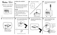
<strong>RM7897A</strong>,C <strong>7800</strong> <strong>SERIES</strong> RELAY MODULESWiring SubbaseWARNINGElectrical Shock Hazard.Can cause severe injury, death or equipmentdamage.Disconnect the power supply before beginninginstallation. More than one disconnect may berequired.The internal block diagram of the <strong>RM7897A</strong>,C is shown inFig. 1.1. For proper subbase wiring and sequence chart, refer toFig. 2 and 3.2. For remote wiring of the Keyboard Display Module, referto the Specifications for the Keyboard Display Module(65-0288), Data ControlBus Module (65-0091) orExtension Cable Assembly (65-0131).3. Disconnect the power supply from the main disconnectbefore beginning installation to prevent electrical shockand equipment damage. More than one disconnect canbe required.4. All wiring must comply with all applicable electricalcodes, ordinances and regulations. Wiring, whererequired, must comply with NEC, Class 1 (Line Voltage)wiring.5. For recommended wire size and type, see Table 1.6. For recommended grounding practices, see Table 2.120 VAC,50/60 HZ211DDL2 6K1REMOTECOMMUNICATIONS3 4RESETBLOWER3K1L1(HOT)L211 PROVIDE DISCONNECT MEANS AND 5OVERLOAD PROTECTION AS REQUIRED.2 <strong>RM7897A</strong>-INTERMITTENT PILOT.PLUG-IN PURGERM7897C-INTERRUPTED PILOT.CONFIGURATIONTIMER CARDJUMPERS3 <strong>RM7897A</strong>-INTERRUPTED PILOT.TESTRM7897C-DELAYED MAIN VALVE.FLAME SIGNALJACKRUN/TESTSWITCHINDICATES FEEDBACK SENSINGPLUG-INTO RELAY STATUS FEEDBACKMICROCOMPUTER TEST FLAMEAND LINE VOLT INPUTSAMPLIFIERFG22FIELD WIRING2KINTERNAL WIRINGRESETPUSHBUTTONRELAYRELAY3KSTATUSDRIVE 4KFEEDBACKCIRCUIT5KAND LINEVOLTAGE6KINPUTS7KSTATUS LEDsSAFETY RELAY 1KCIRCUITPOWER SUPPLYCONTROLPOWER1K1 2K1 5K16 710 IGNITIONLIMITS CONTROLLER LOCKOUT4K1INTERLOCK8 PILOT(INCLUDINGOPTIONAL KEYBOARDAIRFLOW SWITCH) 2K2DDL DISPLAY MODULE9 MAIN VALVEPREIGNITIONRS485INTERLOCK207K16M22727A3 ALARML223Fig. 1. Internal block diagram of <strong>RM7897A</strong>,C (see Fig. 2 and 3 for detailed wiring instructions).7. Recommended wire routing of leadwires:a. Do not run high voltage ignition transformer wiresin the same conduit with the flame detector, DataControlBus Module, or Remote Reset Modulewiring.b. Do not route flame detector, Data ControlBusModule, or Remote Reset Module leadwires inconduit with line voltage circuits.c. Enclose flame detector leadwires without armorcable in metal cable or conduit.d. Follow directions in flame detector, DataControlBus Module, or Remote Reset ModuleInstructions.8. The KDM is powered from a low voltage, energy limitedsource. It can be mounted outside of a control panel if itis protected from mechanical damage.NOTE:A 13 Vdc power supply must be used any time morethan one KDM is used.3 66-1151—05
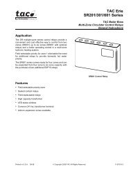
<strong>RM7897A</strong>,C <strong>7800</strong> <strong>SERIES</strong> RELAY MODULESQ<strong>7800</strong>G12FOR DIRECT SPARK IGNITION(OIL OR GAS)LINE VOLTAGEALARML231314108IGNITIONTRANSFORMERL2BURNER MOTOR(BLOWER)4159MAIN VALVE5(L1)16BURNERCONTROLLER/LIMITS617RUNNING INTERLOCK(INCLUDINGAIRFLOW SWITCH).718210 SEC. INTERRUPTEDPILOT/IGNITIONMAIN FUEL VALVE(S)IGNITION8910192021DELAYED(2ND STAGE)MAIN VALVEPREIGNITIONINTERLOCKFLAME DETECTOR4F22MASTERSWITCHL1(HOT)1L2INITIATE(INITIALPOWERUPONLY)PFEP00 TIMED 510 SEC.00(4 SEC. IF10 6 2000 3STANDBY PREPURGE JR1 CLIPPED MFEP RUN POSTPURGESTANDBYPOWERPOWERPOWERPOWERPOWERPOWERPOWERPOWERLEDDISPLAYPILOTFLAMEMAINALARMPILOTFLAMEMAINALARMPILOTFLAMEMAINALARMPILOTFLAMEMAINALARMBURNERBURNER/BLOWER MOTOR410IGNITIONINTERRUPT/PILOT8MAIN VALVE9DELAYED MAIN VALVE21OPERATINGCONTROLSANDINTERLOCKSLIMITS AND BURNER CONTROLLER CLOSEDRUNNING INTERLOCKL1 TO 66 TO 7PREIGNITION INTERLOCK CLOSED5TO20PIIFLAMESIGNALSAFE START CHECKFLAME PROVINGSSC123120 VAC, 50/60 HZ POWER SUPPLY. PROVIDE DISCONNECT MEANSAND OVERLOAD PROTECTION AS REQUIRED.DO NOT CONNECT ANY WIRES TO UNUSED TERMINALS.PROGRAMMABLE POST PURGE TIMING USING S<strong>7800</strong>A1142 KDM.456SEE FLAME DETECTOR SPECIFICATIONS FOR CORRECT WIRING.PURGE TIME DEPENDS ON WHICH ST<strong>7800</strong> IS INSTALLED.RM7897C1018 IS 14 SECONDS FOR 4 SECOND MFEP.M22729CFig. 3. Wiring subbase and sequence chart for RM7897C.5 66-1151—05
<strong>RM7897A</strong>,C <strong>7800</strong> <strong>SERIES</strong> RELAY MODULESaTable 1. Recommended Wire Sizes and Part Numbers.Application Recommended Wire Size Recommended Part NumbersLine voltage terminals. 14, 16 or 18 AWG copper conductor, 600 volt insulation, TTW60C, THW75C, THHN90C.moisture-resistant wire.Keyboard Display Module 22 AWG two-wire twisted pair with ground, or five-wire. Belden 8723 shielded cable or equivalent.Data ControlBus Module a 22 AWG two-wire twisted pair with ground, or five-wire. Belden 8723 shielded cable or equivalent.Remote Reset Module 22 AWG two-wire twisted pair, insulated for low voltage. —13 Vdc full-wave rectifiedtransformer power input.The KDM or Data ControlBus Module (for remote mounting or communications) must be wired in daisy chain configuration,1(a)-1(a), 2(b)-2(b), 3(c)-3(c). The order of interconnection of all the devices listed above is not important. Be aware that moduleson the closest and farthest end of the daisy chain configuration string require a 120 ohm (1/4 watt minimum) resistor terminationacross terminals 1 and 2 of the electrical connectors for connections over 100 feet (31 meters).Ground TypeEarth ground (subbase and relaymodule).Signal ground (Keyboard DisplayModule, Data ControlBus Module.18 AWG wire insulated for voltages and temperaturesfor given application.9. Maximum wire lengths:a. <strong>RM7897A</strong>,C leadwires: The maximum leadwirelength is 300 feet to terminal inputs (Control,Running/Lockout Interlock).b. Flame Detector leadwires: The maximum flamesensor leadwire length is limited by the flame signalstrength.c. Remote Reset leadwires: The maximum length ofwire is 1000 feet (305 meters) to a Remote Resetpush button.d. Data ControlBus Module: The maximum DataControlBus Module cable length depends on thenumber of system modules connected, the noiseconditions and the cable used. The maximum lengthof all Data ControlBus Module interconnectingwire is 4000 feet (1219 meters).10. Be sure loads do not exceed the terminal ratings. Referto the label on the <strong>RM7897A</strong>,C or to the terminal ratingsin Table 3.Table 2. Recommended Grounding Practices.Recommended PracticeTTW60C, THW75C, THHN90C.1. Use to provide a connection between the subbase and the control panel of theequipment. Earth ground must be capable of conducting enough current to blow the15A, type SC,. fast blow fuse (or breaker) in the event of an internal short circuit.2. Use wide straps or brackets to provide minimum length, maximum surface areaground conductors. If a leadwire is required, use 14 AWG copper wire.3. Make sure that mechanically tightened joints along the ground path are free ofnonconductive coatings and protected against corrosion on mating surfaces.Use the shield of the signal wire to ground the device to the signal ground terminal 3(c) ofeach device. Connect the shield at both ends of the daisy chain to earth ground.Final Wiring Check1. Check the power supply circuit. The voltage andfrequency tolerance must match those of the<strong>RM7897A</strong>,C. A separate power supply circuit can berequired for the <strong>RM7897A</strong>,C. Add the requireddisconnect means and overload protection.2. Check all wiring circuits and complete Static Checkoutin Table 6 before installing the <strong>RM7897A</strong>,C on thesubbase.3. Install all electrical connectors.4. Restore power to the panel.STATIC CHECKOUTAfter checking all wiring, perform this checkout beforeinstalling the <strong>RM7897A</strong>,C on the subbase. These tests verifythe Q<strong>7800</strong> Wiring Subbase is wired correctly, and the externalcontrollers, limits, interlocks, actuators, valves, transformers,motors and other devices are operating properly.66-1151—05 6
<strong>RM7897A</strong>,C <strong>7800</strong> <strong>SERIES</strong> RELAY MODULESWARNINGFire or Explosion Hazard.Can cause property damage, severe injuryor death.Close all manual fuel shutoff valve(s) before startingthese tests.Use extreme care while testing the system. Linevoltage is present on most terminal connections whenpower is on.Ensure proper selection of configuration jumpers beforestarting the burner operation.CAUTIONElectrical Hazard.Can cause equipment damage or failure.Do not perform a dielectric test with the relay moduleinstalled. Internal surge protectors can break down,allowing relay module to fail the dielectric test anddestroy the internal lightning and high currentprotection.1. Open the master switch before installing or removing ajumper on the subbase.2. Before continuing to the next test, be sure to remove thetest jumper(s) used in the previous test.3. Replace all limits and interlocks that are not operatingproperly. Do not bypass limits and interlocks.Equipment Recommended1. Voltmeter (1M ohm/volt minimum sensitivity) set on the0 to 300 Vac scale.2. Two jumper wires, no. 14 wire, insulated, 12 in.(304.8 mm) long with insulated alligator clips at bothends.General Instructions1. Perform all applicable tests listed in Static Checkout,Table 6, in the order listed.2. Make sure all manual fuel shutoff valve(s) are closed.3. For each test, open the master switch and install thejumper wire(s) between the subbase wiring terminalslisted in the Test Jumpers column.4. Close the master switch before observing operation.5. Read the voltage between the subbase wiring terminalslisted in the Voltmeter column.6. If there is no voltage or the operation is abnormal, checkthe circuits and external devices as described in the lastcolumn.7. Check all wiring for correct connections, tight terminalscrews, correct wire, and proper wiring techniques.Replace all damaged or incorrectly sized wires.8. Replace faulty controllers, limits, interlocks, actuators,valves, transformers, motors and other devices, asrequired.9. Make sure normal operation is obtained for eachrequired test before continuing the checkout.10. After completing each test, be sure to open the masterpower switch and remove the test jumper(s) beforeproceeding to the next test.WARNINGExplosion hazard.Can cause serious injury or death.Be sure all manual fuel shutoff valves are closed.Mounting <strong>RM7897A</strong>,C <strong>Relay</strong> Module1. Mount the <strong>RM7897A</strong>,C vertically on the Q<strong>7800</strong>Subbase or mount horizontally with the knife bladeterminals pointing down. When mounted on theQ<strong>7800</strong>A, the <strong>RM7897A</strong>,C must be in an electricalenclosure.2. When mounting in an electrical enclosure, provideadequate clearance for servicing, installation andremoval of the <strong>RM7897A</strong>,C, KDM, flame amplifier, flameamplifier signal voltage probes, electrical signal voltageprobes and electrical connections.e. Allow an optional three-inch (76 mm) minimum onboth sides of the <strong>RM7897A</strong>,C for electrical signalvoltage probes.3. Make sure no subbase wiring is projecting beyond theterminal blocks. Tuck in wiring against the back of thesubbase so it does not interfere with the knife bladeterminals or bifurcated contacts.IMPORTANTThe <strong>RM7897A</strong>,C, must be installed with a plug-inmotion rather than a hinge action.4. Mount the <strong>RM7897A</strong>,C by aligning the four L-shapedcorner guides and knife blade terminals with thebifurcated contacts on the wiring subbase and securelytightening the two screws without deforming the plastic.66-1151—05 8
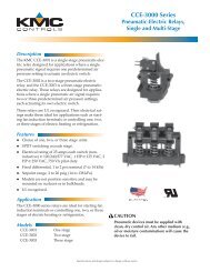
<strong>RM7897A</strong>,C <strong>7800</strong> <strong>SERIES</strong> RELAY MODULESTestNumber<strong>Relay</strong> ModuleModelTestJumpers VoltmeterTable 6. Static Checkout.Normal OperationIf Operation is Abnormal,Check Items Listed Below1 All None 5-L2 Line voltage at terminal 5. 1. Master switch.2. Power connected to master switch.3. Overload protection (fuse, circuit breaker,etc.) has not opened power line.2 All None 6-L2 Line voltage at terminal 6. 1. Limits.2. Burner controller.3 All 4-5 7-L2 1. Burner motor (fan or blower)starts.2. Line voltage at terminal 7within 10 seconds.4 All 5-10 — 1. Ignition spark (if ignitiontransformer is connected toterminal 10).1. Burner motor circuit.a. Manual switch of burner motor.b. Burner motor power supply, overloadprotection and starter.c. Burner motor.1. Watch for spark or listen for buzz.a. Ignition electrodes are clean.b. Ignition transformer is okay.5 All 20-L2 Line voltage at Terminal 20 Preignition Interlocks.6 All 5-8 — 1. Ignition spark (if ignitiontransformer is connected toterminal 8).2. Automatic pilot valve opens(if connected to terminal8).NOTE:Refer to wiring diagramof system being tested.7 All 5-9 — Automatic fuel valve(s) open(s). Ifusing direct spark ignition, checkfirst stage fuel valve(s) instead ofpilot valve.8a <strong>RM7897A</strong> 5-21 — 1. Ignition spark (if ignitionconnected to terminal21).2. Automated Pilot Valveopens (if connected toterminal 21).NOTE:Refer to wiring diagramof system being tested.8b RM7897C 5-21 — Automatic second stage main fuelvalve(s) open(s).1. Watch for spark or listen for buzz.2. Listen for click or feel head of valve foractivation.a. Actuator if used.b. Pilot valve.Same as test 6. If using direct sparkignition, check first stage fuel valve(s)instead of pilot valve.1. Watch for spark or listen for buzz.2. Listen for click or feel head of valve foractivation.a. Actuator if used.b. Pilot valve.1. Listen for and observe operation ofsecond stage main fuel valve(s) andactuator(s).2. Valve(s) and actuator(s).9 All 5-3 — Alarm (if used) turns on. 1. Alarm.Final AllCAUTIONEquipment Damage Hazard.Can cause equipment damage.After completing these tests, open master switch and remove all test jumpers from subbaseterminals. Also remove bypass jumpers, if used, from low fuel pressure limits.Mounting Other System Components(Fig. 4)Refer to the applicable specifications for mounting othersystem components.Setup of Post PurgeAn S<strong>7800</strong>A1142, Keyboard Display Module (KDM), isrequired for the setup of the RM7897 Post Purge Timing, andmust be purchased separately.When the <strong>RM7897A</strong>,C is installed and powered, “STANDBY”will be shown on the first line of the display (Fig. 5).9 66-1151—05
<strong>RM7897A</strong>,C <strong>7800</strong> <strong>SERIES</strong> RELAY MODULESWIRINGSUBBASERUN/TEST (C,D ONLY)SWITCHHONEYWELLRELAYMODULECONFIGURATIONJUMPERSPURGETIMERSEQUENCESTATUSLED PANELKEYBOARDDISPLAYMODULERESETBUTTONPOWERPILOTFLAMEMAINALARMRESETCAPTIVEMOUNTINGSCREWBURNER CONTROLFLAMEAMPLIFIEREDIT:_ +BACK- ENTER -M22827Fig. 4. <strong>RM7897A</strong>,C <strong>Relay</strong> Module, exploded view.STANDBYSetupSTANDBY± BC Password: 00SUBACKBACKEdit: - +ENTEREdit: - +ENTERM22662BM22663BFig. 5. Setup Needed screen.1. Scroll down until “Setup” is displayed in the second line.2. Enter the setup sub-routine by pressing the far rightarrow key on the display.Fig. 6. Entering the setup sub-routine.The second line reads “BC Password”.3. Use the up/down arrows to enter the first number, 7.4. Use the far right arrow key to shift over one space.5. Use the up/down arrows to enter the second number, 8.6. Press Enter (left/right arrow simultaneously).66-1151—05 10
<strong>RM7897A</strong>,C <strong>7800</strong> <strong>SERIES</strong> RELAY MODULES=Select=RestartCONFIRM: Postpurge±PostTime: 00:30 ?SCEdit: - +BACKENTEREdit: - +BACKENTERM22764BM22674AFig. 7. Select/Restart screen.7. Press down arrow to select.8. “Getting Data” will be momentarily displayed, followedby the screen shown in Fig. 8.1. Press Enter.Fig. 10. Confirm Postpurge time.SETUP:Postpurge±PostTime: 00:30SUEdit: - +=Confirm correct=IncorrectBACKENTEREdit: - +BACKENTERM22671BM22668Fig. 11. Confirm correct/incorrect screen.Fig. 8. Setting Post Purge time.This screen allows for setting up the Postpurge for the<strong>RM7897A</strong>,C. This will be the time that the Combustion Fan(terminal 4) will remain energized after the call for heat hasended (terminal 6).9. Use the up arrow to increase the postpurge time.Time increases:2. Press the down arrow to confirm the correct postpurgetime. “Getting Data” will be displayed until the screen inFig. 12 appears.SETUP DONE: PressReset for 5 sec . . .0 to 60 seconds in 1 second intervals.60 to 600 seconds in 10 second intervals.Edit: - +BACKENTERM22676B10 to 60 minutes in 1 minute intervals.10. Press Enter (Left/Right arrow keys simultaneously)when the correct postpurge time is displayed.Fig. 12. Setup Done screen.3. Go to the RM7897 and press and hold the reset buttonfor five seconds to program the postpurge time into therelay module.The Release Reset screen will appear on the KDM.=Save changes=RestartEdit: - +BACKENTERSETUP DONE:... release ResetFig. 9. Save Changes screen.M22665B11. Use the down arrow to save changes. “Getting Data” isdisplayed momentarily.The following steps are used to confirm your selection.Edit: - +BACKENTERFig. 13. Release Reset screen.M22765BChanging the postpurge time feature is still possible. With theRM7897 in Standby, scrolling to the Setup line and enteringwith the password allows the settings to be changed.Once the system is in operation, the settings of the postpurgetime can be viewed under Diagnostics, using your S<strong>7800</strong>Keyboard Display Module.11 66-1151—05
<strong>RM7897A</strong>,C <strong>7800</strong> <strong>SERIES</strong> RELAY MODULESPRINCIPAL TECHNICALFEATURESThe RM7897 provides all customary flame safeguardfunctions as well as significant advancements in safety,annunciation, and system diagnostics.Safety Shutdown (Lockout) Occursif:1. INITIATE PERIODa. Purge card is not installed or removed.b. Purge card is bad.c. Configuration jumpers have been changed (after200 hours)—Fault Code 110.d. AC line power errors occurred, see Operation.e. Four minute INITIATE period has been exceeded.2. STANDBY PERIODa. Airflow lockout feature is enabled (JR3 clipped) andthe airflow switch does not close after ten secondsor within the specified purge card timing.b. Flame signal is detected after 240 seconds.c. Ignition/pilot valve terminal is energized.d. Main valve terminal is energized.e. Delayed main valve terminal is energized(RM7897C).f. Internal system fault occurred.g. Purge card is removed.h. Purge card is bad.i. PreIgnition Interlock open.3. PREPURGE PERIODa. Airflow lockout feature is enabled (JR3 clipped) andthe airflow switch opens.b. Ignition/pilot valve terminal is energized.c. Main valve terminal is energized.d. Delayed main valve terminal is energized(RM7897C).e. Internal system fault occurred.f. Purge card is removed.g. Purge card is bad.h. Flame signal is detected for 30 seconds.i. Preignition interlocks open during standby.4. PILOT FLAME ESTABLISHING PERIOD (PFEP)a. Airflow lockout feature is enabled and the airflowswitch opens.b. No flame signal at end of PFEP.c. Ignition/pilot valve/intermittent pilot valve terminal isnot energized.d. Main valve terminal is energized (<strong>RM7897A</strong>).e. Delayed (second stage) main valve terminal isenergized (RM7897C).f. Internal system fault occurred.g. Purge card is removed.h. Purge card is bad.5. MAIN FLAME ESTABLISHING PERIOD (MFEP)a. Airflow lockout feature is enabled and the airflowswitch opens.b. Ignition terminal is energized.c. Ignition/pilot valve terminal is not energized.d. Main valve terminal is not energized.e. Delayed main valve terminal is energized.f. Loss of flame signal.g. Internal system fault occurred.h. Purge card is removed.i. Purge card is bad.6. RUN PERIODa. No flame present (JR2 removed). ab. Airflow lockout feature is enabled and the airflowswitch opens.c. Interrupted pilot valve terminal is energized(<strong>RM7897A</strong>, terminal 21; RM7897C, terminal 8).d. Main valve terminal is not energized.e. Delayed main valve terminal is not energized(RM7897C).f. Internal system fault occurred.g. Purge card is removed.h. Purge card is bad.i. Ignition terminal is energized.Safety Shutdown Sequence:1. A safety shutdown occurring during Initiate or Standbywill lockout the RM7897 (prevent it from starting) indicatedby an alarm.2. A safety shutdown occurring during purge results theblower motor terminal 4 being de-energized and thesystem will lockout indicated by an alarm.3. A safety shutdown during the ignition trial period (pilot ormain) or Run, all fuel valves and the ignition (if on) willbe de-energized and the system will lockout indicatedby an alarm. The RM7897 will complete the programmedpost purge before the blower motor terminal 4is de-energized. If no post purge is programmed, theRM7897 will default to a 15 second post purge.Manual reset is required following any safety shutdown.Manual reset may be accomplished by pressing the pushbutton on the device, pressing the remote reset wired throughan attached display or S7820 remote reset module.NOTE:Interrupting power will cause electrical resets, butdoes not reset a safety shutdown (lockout) condition.OPERATIONSequence of OperationThe <strong>RM7897A</strong>,C has the operating sequences listed below;see Fig. 2 and 3. The <strong>RM7897A</strong>,C LED provide positive visualindication of the program sequence: POWER, PILOT, FLAME,MAIN and ALARM.InitiateThe <strong>RM7897A</strong>,C <strong>Relay</strong> Module enters the INITIATE sequencewhen the relay module is initially powered. The <strong>RM7897A</strong>,Ccan also enter the INITIATE sequence if the relay moduleverifies voltage fluctuations of +10/-15% or frequencyfluctuations of ±10% during any part of the operating sequence.The INITIATE sequence lasts for ten seconds unless thevoltage or frequency tolerances are not met. When not met, ahold condition is initiated and displayed on the optional KDM forat least five seconds; when met, the INITIATE sequencerestarts. If the condition is not corrected and the hold conditionexists for four minutes, the <strong>RM7897A</strong>,C locks out. Causes forhold conditions in the INITIATE sequence:1. AC line dropout detection.2. AC line noise that can prevent a sufficient reading of theline voltage inputs.3. Low line voltage brownouts.a For RM7897C1026, if flame loss occurs during the first 15seconds in the Run period, then lockout occurs. If flame lossoccurs after 15 seconds into the Run period, then recycle.66-1151—05 12
<strong>RM7897A</strong>,C <strong>7800</strong> <strong>SERIES</strong> RELAY MODULESThe INITIATE sequence also delays the burner motor starterfrom being energized and de-energized from an intermittentAC line input or control input.StandbyThe <strong>RM7897A</strong>,C is ready to start an operating sequencewhen the operating control input determines a call for heat ispresent. The burner switch, limits, operating limit control andall microcomputer-monitored circuits must be in the correctstate for the relay module to continue into the PREPURGEsequence.Normal Start-Up PrepurgeThe <strong>RM7897A</strong>,C <strong>Relay</strong> Module provides PREPURGE timing,selectable with ST<strong>7800</strong> Purge Timer cards, from two secondsto thirty minutes with power applied and the operating controlindicating a call for heat.1. The Airflow Interlock, burner switch, Run/Test switchand all microcomputer-monitored circuits must also bein the correct operating state.2. The motor output, terminal 4, is powered to start thePREPURGE sequence.3. The Airflow Interlock input closes ten seconds intoPREPURGE or within the specified purge card timing;otherwise, a recycle to the beginning of PREPURGE orlockout occurs, depending on how the Airflow Switchselectable jumper (JR3) is configured.Ignition Trials1. Pilot Flame Establishing Period (PFEP):a. When the PFEP begins:(1) The pilot valve and ignition transformer,terminals 8 and 10 (also terminal 21, <strong>RM7897A</strong>),are energized. The <strong>RM7897A</strong> has an intermittentpilot valve, terminal 8, and interrupted pilot valveon terminal 21. The RM7897C has aninterrupted pilot valve, terminal 8.(2) Flame must be proven by the end of the tensecond PFEP (four seconds if ConfigurationJumper JR1 is clipped) to allow the sequence tocontinue. If a flame is not proven by the end ofPFEP, a safety shutdown occurs.(3) the Pre-Ignition Interlock is ignored throughoutthe Trial for Ignition State.2. Main Flame Establishing Period (MFEP):a. After PFEP, and with the presence of flame,the main fuel valve, terminal 9, is powered. If aflameout occurs, the relay module locks out within0.8 or 3 seconds, depending on the Flame FailureResponse Time (FFRT) of the amplifier.b. The <strong>RM7897A</strong> (terminal 21) and RM7897C(terminal 8) have a ten second MFEP(RM7897C1018 is four seconds). After the IgnitionTrials, the interrupted pilot valve, terminal 8 or 21, isde-energized. If a flameout occurs, the relay modulerecycles (locks out if jumper JR2 clipped) within 0.8or 3 seconds, depending on the Flame FailureResponse Time (FFRT) of the amplifier.Run1. The RM7897C has a delayed main valve that isenergized once the RUN period is entered.2. The relay module is now in RUN and remains in RUNuntil the controller input, terminal 6, opens, indicatingthat the demand is satisfied or a limit has opened.Post PurgeAfter the demand is satisfied or a limit opens, de-energizingterminal 6, the Ignition/Pilot valve, main valve and delayedmain valve, terminals 8, 9 and 21, are de-energized. Theblower motor, terminal 4, remains powered during thespecified programmed time. The Pre-Ignition Interlock closeswithin the first five seconds of Post Purge.Run/Test SwitchThe Run/Test Switch is located on the top side of the relaymodule, see Fig. 12. The Run/Test Switch allows the burnersequence to be altered as follows:1. In the measured PREPURGE sequence, the Run/TestSwitch, placed in the TEST position, causes thePREPURGE timing to stop.2. In the Pilot Flame Establishing Period, the Run/TestSwitch, placed in the TEST position, stops the timerduring the first eight seconds of a ten-second PFEPselection or during the first three seconds of afour-second PFEP selection. It also allows for pilotturn-down test and other burner adjustments. Thisactivates a fifteen-second flameout timer that permitspilot flame adjustment without nuisance safetyshutdowns. The Run/Test Switch is ignored duringPFEP for the C relay module if terminals8 and 9 or 9 and 21 are jumpered.IMPORTANTWhen the relay module is switched to the TESTmode, it stops and holds at the next Run/Test Switchpoint in the operating sequence. Make sure that theRun/Test Switch is in the RUN position beforeleaving the installation.RUN/TEST SWITCHSEQUENCESTATUSLEDsRESETPUSHBUTTONFLAMESIMULATOR INPUTFig. 14. Sequence Status LEDs.CAPTIVEMOUNTINGSCREWPLUG-INPURGECARDDUSTCOVERRELAYMODULEFLAMEAMPLIFIERFLAME CURRENTTEST JACKS M7552ASETTINGS AND ADJUSTMENTSSelectable Site-ConfigurableJumpersThe relay module has three site-configurable jumper options,see Fig. 13 and Table 7. If necessary, clip the site-configurablejumpers with side cutters and remove the resistors from therelay module.SERVICE NOTE: Clipping and removing a site-configurablejumper enhances the level of safety.13 66-1151—05
<strong>RM7897A</strong>,C <strong>7800</strong> <strong>SERIES</strong> RELAY MODULESIMPORTANTClipping and removing a jumper after 200 hours ofoperation causes a nonresettable Fault 110. Therelay module must then be replaced.SELECTABLE CONFIGURATION JUMPERSRUN/TEST SWITCH(EC7895C; RM7895C,D; RM7896C,D)Table 7. Site-configurable jumper options.JumperNumber Description Intact ClippedJR1Pilot Flame EstablishingPeriod (PFEP)10seconds4secondsJR2 Flame Failure Action Recycle Lockout aJR3 Airflow Switch (ILK) Failure Recycle Lockouta For RM7897C1026, if flame loss occurs during the first 15seconds in the Run period, then lockout occurs. If flameloss occurs after 15 seconds into the Run period, thenrecycle.TROUBLESHOOTINGM7553AFig. 15. Selectable site-configurable jumpers.The POWER LED provides fault identification when the <strong>Relay</strong>Module locks out on an alarm. Fault identification is a series offast- and slow-blinking LED lights. The fast blinks identify thetens portion of the fault code (three fast blinks is 30), while theslow blinks identify the units portion of the fault code (two slowblinks is 2). Three fast blinks followed by two slow blinkswould be fault code 32. This identifies a running interlock onduring STANDBY. (See Table 8 for Blinking Fault Code List.)The LED code repeats as long as the fault exists. To clear thefault, press the RESET button.NOTE:Blink codes do not match fault codes viewed by anS<strong>7800</strong> KDM.Table 8. Blinking Fault Codes and Recommended Troubleshooting.Fault Code System Failure Recommended TroubleshootingCode 1-1*Low AC LineVoltage*Code 1-2*AC QualityProblem*Code 2-1*UnexpectedFlame Signal*Code 2-2*Flame SignalAbsent*Low AC Linedetected.Excessive noise ordevice running onslow, fast, or AC linedropout detected.Flame sensedwhen no flame isexpected duringSTANDBY orPURGE.No-flame timepresent at the endof the PIlot FlameEstablishing Period;lost during the MainFlame EstablishingPeriod or duringRUN.1. Check the relay module and display module connections.2. Reset and sequence the <strong>Relay</strong> Module.3. Check the <strong>7800</strong> power supply and make sure that frequency and voltage meetspecifications.4. Check the backup power supply, as appropriate.1. Check that flame is not present in the combustion chamber; correct any errors.2. Make sure that the flame amplifier and flame detector are compatible.3. Check the wiring and correct any errors.4. Remove the flame amplifier and inspect its connections. Reseat the amplifier.5. Reset and sequence the relay module.6. If the code reappears, replace the flame amplifier and/or the flame detector.7. If the fault persists, replace the relay module.1. Measure the flame signal. If one exists, verify that it meets specifications.2. Make sure that the flame amplifier and flame detector are compatible.3. Inspect the main fuel valve(s) and valve connection(s).4. Verify that the fuel pressure is sufficient to supply fuel to the combustion chamber. Inspect theconnections to the fuel pressure switches. Make sure they are functioning properly.5. Inspect the Airflow Switch and make sure that it is functioning properly.6. Check the flame detector sighting position; reset and recycle. Measure the flame signalstrength. Verify that it meets specifications. If not, refer to the flame detector and/or flameamplifier checkout procedures in the installation instructions.7. Replace the flame amplifier and/or the flame detector, if necessary.8. If the fault persists, replace the relay module.66-1151—05 14
Code 2-3*Flame SignalOverrange*Flame signal valueis too high to bevalid.<strong>RM7897A</strong>,C <strong>7800</strong> <strong>SERIES</strong> RELAY MODULESTable 8. Blinking Fault Codes and Recommended Troubleshooting. (Continued)Fault Code System Failure Recommended TroubleshootingCode 3-1*Running/InterlockSwitchProblem*Code 3-2*Running/Interlock OnDuringStandby*Code 3-3*VPS inImproperState*Code 4-1*Purge CardProblem*Code 4-2*WiringProblem/Internal Fault*Code 4-3*FlameAmplifierProblem*Code 4-4*ConfigurationJumperProblem*Running or LockoutInterlock fault duringPrepurge.Lockout Interlockpowered atimproper point insequence or On inStandby.VPS (Valve ProvingSwitch) in wrongstate during VPSTest.No purge card orthe purge cardtiming has changedfrom the originalconfiguration.Pilot (ignition) valveterminal, mainvalve, ignition orMain Valve 2 wason when it shouldbe off.Flame not sensed,or sensed when itshould be on or off.The configurationjumpers differ fromthe sample taken atstartup.1. Make sure the flame detector and flame amplifier are compatible.2. Remove the flame amplifier and inspect its connections. Reset the flame amplifier.3. Reset and sequence the relay module.4. Check the flame detector sighting position; reset and recycle. Measure flame strength. Verifythat it meets specifications. If not, refer to the flame detector and/or flame amplifier checkoutprocedures in the installation instructions.5. If the code reappears, replace the flame amplifier and/or the flame detector.6. If the fault persists, replace the relay module.1. Check wiring; correct any errors.2. Inspect the fan; make sure there is no air intake blockage and that it is supplying air.3. Make sure the Lockout Interlock switches are functioning properly and the contacts are freefrom contaminants.4. Reset and sequence the relay module to Prepurge (place the TEST/RUN Switch in theTEST position, if available). Measure the voltage between terminal 7 and G (ground); 120Vac should be present. Switch TEST/RUN back to RUN.5. If steps 1 through 4 are correct and the fault persists, replace the relay module.1. Check wiring to make sure that the Lockout Interlocks are connected properly betweenterminals 6 and 7. Correct any errors.2. Reset and sequence the relay module.3. If the fault persists, measure the voltage between terminal 6 and G (ground), then betweenterminal 7 and G. If there is 120 Vac at terminal 6 when the controller is off, the controllerswitch may be bad or is jumpered.4. If steps 1 through 3 are correct and there is 120 Vac at terminal 7 when the controller isclosed and the fault persists, check for a welded or jumpered Running Interlock or AirflowSwitch. Correct any errors.5. If steps 1 through 4 are correct and the fault persists, replace the relay module.1. Check wiring, making sure upstream valve is connected to terminal 9 and downstream valveis connected to terminal 17.2. Conduct Valve Seat leakage test using a manometer.3. Reset and sequence the relay module; if fault repeats, test VPS (connected to terminal 16) isfunctioning properly; replace if necessary.4. Reset and sequence the relay module.5. If fault persists, replace the relay module.1. Make sure the purge card is seated properly.2. Inspect the purge card and the connector on the relay module for any damage or contaminants.3. Reset and sequence the relay module.4. If the fault code reappears, replace the purge card.5. Reset and sequence the relay module.6. If the fault code persists, replace the relay module.WARNINGElectrical Shock Hazard; Fire or Explosion Hazard.Can cause severe injury, death or property damage.Remove system power and turn off power supply.1. Remove system power and turn off fuel supply.2. Check wiring; correct any errors.3. inspect Pilot Fuel Valve(s), both places, and connections.4. Reset and sequence the relay module.5. If the fault persists, replace the relay module.1. Check wiring; correct any errors.2. Make sure the flame amplifier and flame detector are compatible.3. Remove the flame amplifier and inspect the connections. Reseat the amplifier.4. Reset and sequence the relay module.5. If the code reappears, replace the flame amplifier and/or the flame detector.6. If the fault persists, replace the relay module.1. Inspect the jumper connections. Make sure the clipped jumpers were completely removed.2. Reset and sequence the relay module.3. If the fault persists, replace the relay module.15 66-1151—05
<strong>RM7897A</strong>,C <strong>7800</strong> <strong>SERIES</strong> RELAY MODULESTable 8. Blinking Fault Codes and Recommended Troubleshooting. (Continued)Fault Code System Failure Recommended TroubleshootingCode 5-1*PreignitionInterlock*Code 5-2*High Fire Sw.or Low FireSw.*Code 5-3*Man-OpenSw.; Start Sw.or Control On*Code 6-1*InternalFaults*Code 6-2*InternalFaults*Code 6-3*DeviceSpecific*Code 6-4*AccessoryFault*Code 7-7*Unused*Preignition Interlockfault.Either High FireSwitch or Low FireSwitch failure.Man-Open Switch,Start Switch orControl On in thewrong operationalstate.<strong>Relay</strong> Module selftestfailure.<strong>Relay</strong> Module Self-Test failure.Fault with specialOEM input circuits.Unused at this time. —Unused at this time. —1. Check wiring and correct any errors.2. Check Preignition Interlock switches to assure proper functioning.3. Check fuel valve operation.4. Reset and sequence the relay module; monitor the Preignition Interlock status.5. If the fault persists, replace the relay module.1. Check wiring and correct any errors.2. Reset and sequence the relay module.3. Use manual motor potentiometer to drive the motor open and closed. Verify at motor switchthat the end switches are operating properly. Use RUN/TEST switch if manual potentiometeris not available.4. Reset and sequence the relay module.5. If the fault persists, replace the relay module.1. Check wiring and correct any errors.2. Make sure that the Manual Open Valve Switch, Start Switch and Control are operatingproperly.3. Stat Switch held “On” too long.4. Reset and sequence the relay module.5. Reset and sequence the relay module. If the fault persists, replace the relay module(RM7838A1014; RM7838B1013 or RM7838C1004 only).1. Reset and sequence the relay module.2. If fault reappears, remove power from the device, reapply power, then reset and sequencethe relay module.3. If the fault persists, replace the relay module.1. Reset and sequence the relay module.2. If fault reappears, remove power from the device, reapply power, then reset and sequencethe relay module.3. If fault does not repeat on the next cycle, check for electrical noise being copied into the relaymodule through the external loads or possibly an electrical grounding issue.4. If the fault persists, replace the relay module.1. Check wiring and operation of special OEM inputs.2. Reset and sequence the relay module.3. If fault reappears, remove power from the device, reapply power, then reset and sequencethe relay module.4. If the fault does not repeat on the next cycle, check for electrical noise being copied into therelay module through the external loads or possibly an electrical grounding issue.5. If the fault persists, replace the relay module.Automation and Control SolutionsHoneywell International Inc.1985 Douglas Drive NorthGolden Valley, MN 55422Honeywell Limited-Honeywell Limitée35 Dynamic DriveToronto, Ontario M1V 4Z9customer.honeywell.com® U.S. Registered Trademark© 2010 Honeywell International Inc.66-1151—05 K.K. Rev. 07-10Printed in U.S.A.