LM79XX Series 3-Terminal Negative Regulators - Datasheet Catalog
LM79XX Series 3-Terminal Negative Regulators - Datasheet Catalog
LM79XX Series 3-Terminal Negative Regulators - Datasheet Catalog

Create successful ePaper yourself
Turn your PDF publications into a flip-book with our unique Google optimized e-Paper software.
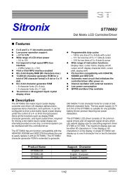
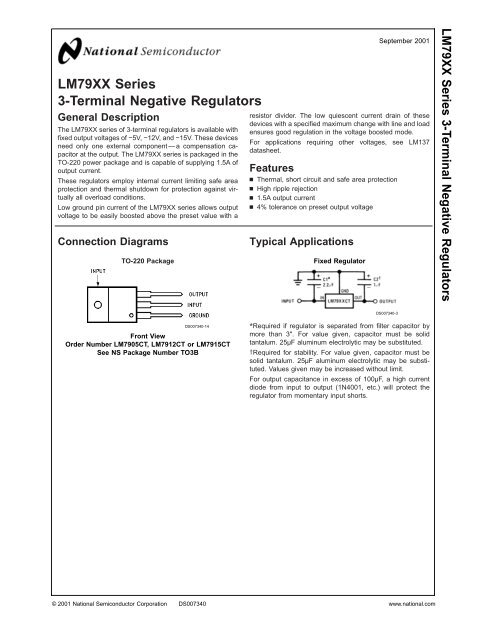
<strong>LM79XX</strong> <strong>Series</strong>3-<strong>Terminal</strong> <strong>Negative</strong> <strong>Regulators</strong>General DescriptionThe <strong>LM79XX</strong> series of 3-terminal regulators is available withfixed output voltages of −5V, −12V, and −15V. These devicesneed only one external component — a compensation capacitorat the output. The <strong>LM79XX</strong> series is packaged in theTO-220 power package and is capable of supplying 1.5A ofoutput current.These regulators employ internal current limiting safe areaprotection and thermal shutdown for protection against virtuallyall overload conditions.Low ground pin current of the <strong>LM79XX</strong> series allows outputvoltage to be easily boosted above the preset value with aConnection DiagramsTO-220 Packageresistor divider. The low quiescent current drain of thesedevices with a specified maximum change with line and loadensures good regulation in the voltage boosted mode.For applications requiring other voltages, see LM137datasheet.Featuresn Thermal, short circuit and safe area protectionn High ripple rejectionn 1.5A output currentn 4% tolerance on preset output voltageTypical ApplicationsFixed RegulatorSeptember 2001<strong>LM79XX</strong> <strong>Series</strong> 3-<strong>Terminal</strong> <strong>Negative</strong> <strong>Regulators</strong>DS007340-3DS007340-14Front ViewOrder Number LM7905CT, LM7912CT or LM7915CTSee NS Package Number TO3B*Required if regulator is separated from filter capacitor bymore than 3". For value given, capacitor must be solidtantalum. 25µF aluminum electrolytic may be substituted.†Required for stability. For value given, capacitor must besolid tantalum. 25µF aluminum electrolytic may be substituted.Values given may be increased without limit.For output capacitance in excess of 100µF, a high currentdiode from input to output (1N4001, etc.) will protect theregulator from momentary input shorts.© 2001 National Semiconductor Corporation DS007340 www.national.com
<strong>LM79XX</strong> <strong>Series</strong>Absolute Maximum Ratings (Note 1)If Military/Aerospace specified devices are required,please contact the National Semiconductor Sales Office/Distributors for availability and specifications.Input Voltage(V o = −5V) −25V(V o = −12V and −15V) −35VElectrical CharacteristicsInput-Output Differential(V o = −5V) 25V(V o = −12V and −15V) 30VPower Dissipation (Note 2)Internally LimitedOperating Junction Temperature Range 0˚C to +125˚CStorage Temperature Range−65˚C to +150˚CLead Temperature (Soldering, 10 sec.)230˚CConditions unless otherwise noted: I OUT = 500mA, C IN = 2.2µF, C OUT = 1µF, 0˚C ≤ T J ≤ +125˚C, Power Dissipation ≤ 1.5W.Part Number LM7905C UnitsOutput Voltage−5VInput Voltage (unless otherwise specified)−10VSymbol Parameter Conditions Min Typ MaxV O Output Voltage T J = 25˚C −4.8 −5.0 −5.2 V5mA ≤ I OUT ≤ 1A, −4.75 −5.25 VP ≤ 15W (−20 ≤ V IN ≤ −7) V∆V O Line Regulation T J = 25˚C, (Note 3) 8 50 mV(−25 ≤ V IN ≤ −7) V2 15 mV(−12 ≤ V IN ≤ −8) V∆V O Load Regulation T J = 25˚C, (Note 3)5mA ≤ I OUT ≤ 1.5A 15 100 mV250mA ≤ I OUT ≤ 750mA 5 50 mVI Q Quiescent Current T J = 25˚C 1 2 mA∆I Q Quiescent Current With Line 0.5 mAChange (−25 ≤ V IN ≤ −7) VWith Load, 5mA ≤ I OUT ≤ 1A 0.5 mAV n Output Noise Voltage T A = 25˚C, 10Hz ≤ f ≤ 100Hz 125 µVRipple Rejection f = 120Hz 54 66 dB(−18 ≤ V IN ≤ −8) VDropout Voltage T J = 25˚C, I OUT = 1A 1.1 VI OMAX Peak Output Current T J = 25˚C 2.2 AAverage Temperature I OUT = 5mA, 0.4 mV/˚CCoefficient of0 C ≤ T J ≤ 100˚COutput VoltageElectrical CharacteristicsConditions unless otherwise noted: I OUT = 500mA, C IN = 2.2µF, C OUT = 1µF, 0˚C ≤ T J ≤ +125˚C, Power Dissipation ≤ 1.5W.Part Number LM7912C LM7915C UnitsOutput Voltage −12V −15VInput Voltage (unless otherwise specified) −19V −23VSymbol Parameter Conditions Min Typ Max Min Typ MaxV O Output Voltage T J = 25˚C −11.5 −12.0 −12.5 −14.4 −15.0 −15.6 V5mA ≤ I OUT ≤ 1A, −11.4 −12.6 −14.25 −15.75 VP ≤ 15W (−27 ≤ V IN ≤ −14.5) (−30 ≤ V IN ≤ −17.5) V∆V O Line Regulation T J = 25˚C, (Note 3) 5 80 5 100 mV(−30 ≤ V IN ≤ −14.5) (−30 ≤ V IN ≤ −17.5) V3 30 3 50 mV(−22 ≤ V IN ≤ −16) (−26 ≤ V IN ≤−20) V∆V O Load Regulation T J = 25˚C, (Note 3)www.national.com 2
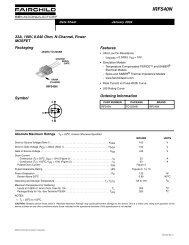
<strong>LM79XX</strong> <strong>Series</strong>Typical ApplicationsBypass capacitors are necessary for stable operation of the<strong>LM79XX</strong> series of regulators over the input voltage andoutput current ranges. Output bypass capacitors will improvethe transient response by the regulator.The bypass capacitors, (2.2µF on the input, 1.0µF on theoutput) should be ceramic or solid tantalum which have goodhigh frequency characteristics. If aluminum electrolytics areused, their values should be 10µF or larger. The bypasscapacitors should be mounted with the shortest leads, and ifpossible, directly across the regulator terminals.High Stability 1 Amp RegulatorDS007340-5Load and line regulation < 0.01% temperature stability ≤ 0.2%†Determine Zener current††Solid tantalum*Select resistors to set output voltage. 2 ppm/˚C tracking suggestedCurrent SourceDS007340-7www.national.com 4
Typical Applications (Continued)Light Controller Using Silicon Photo Cell<strong>LM79XX</strong> <strong>Series</strong>*Lamp brightness increase until i I =i Q (≈1 mA) + 5V/R1.†Necessary only if raw supply filter capacitor is more that 2" from LM7905CTDS007340-8High-Sensitivity Light Controller*Lamp brightness increases until i i = 5V/R1 (I i can be set as low as 1 µA)†Necessary only if raw supply filter capacitor is more that 2" from LM7905DS007340-9Variable Output*Improves transient response and ripple rejection. Do not increase beyond 50 µF.DS007340-2Select R2 as follows:LM7905CT 300ΩLM7912CT 750ΩLM7915CT 1k5www.national.com
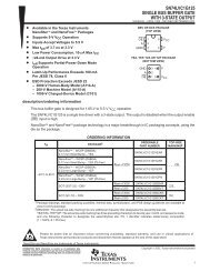
<strong>LM79XX</strong> <strong>Series</strong>Typical Applications (Continued)±15V, 1 Amp Tracking <strong>Regulators</strong>DS007340-1(-15) (+15)Load Regulation at ∆I L = 1A 40mV 2mVOutput Ripple, C IN = 3000µF, I L = 1A 100 µVms 100 µVmsTemperature Stability 50mV 50mVOutput Noise 10Hz ≤ f ≤ 10kHz 150 µVms 150 µVms*Resistor tolerance of R4 and R5 determine matching of (+) and (−) outputs.**Necessary only if raw supply filter capacitors are more than 3" from regulators.Dual Trimmed SupplyDS007340-4www.national.com 6
Schematic DiagramsDS007340-12<strong>LM79XX</strong> <strong>Series</strong>−5V7www.national.com
<strong>LM79XX</strong> <strong>Series</strong>Schematic Diagrams (Continued)−12V and −15VDS007340-13www.national.com 8
Physical Dimensions inches (millimeters) unless otherwise noted<strong>LM79XX</strong> <strong>Series</strong> 3-<strong>Terminal</strong> <strong>Negative</strong> <strong>Regulators</strong>TO-220 Outline Package (T)Order Number LM7905CT, LM7912CT or LM7915CTNS Package Number T03BLIFE SUPPORT POLICYNATIONAL’S PRODUCTS ARE NOT AUTHORIZED FOR USE AS CRITICAL COMPONENTS IN LIFE SUPPORTDEVICES OR SYSTEMS WITHOUT THE EXPRESS WRITTEN APPROVAL OF THE PRESIDENT AND GENERALCOUNSEL OF NATIONAL SEMICONDUCTOR CORPORATION. As used herein:1. Life support devices or systems are devices orsystems which, (a) are intended for surgical implantinto the body, or (b) support or sustain life, andwhose failure to perform when properly used inaccordance with instructions for use provided in thelabeling, can be reasonably expected to result in asignificant injury to the user.2. A critical component is any component of a lifesupport device or system whose failure to performcan be reasonably expected to cause the failure ofthe life support device or system, or to affect itssafety or effectiveness.National SemiconductorCorporationAmericasEmail: support@nsc.comwww.national.comNational SemiconductorEuropeFax: +49 (0) 180-530 85 86Email: europe.support@nsc.comDeutsch Tel: +49 (0) 69 9508 6208English Tel: +44 (0) 870 24 0 2171Français Tel: +33 (0) 1 41 91 8790National SemiconductorAsia Pacific CustomerResponse GroupTel: 65-2544466Fax: 65-2504466Email: ap.support@nsc.comNational SemiconductorJapan Ltd.Tel: 81-3-5639-7560Fax: 81-3-5639-7507National does not assume any responsibility for use of any circuitry described, no circuit patent licenses are implied and National reserves the right at any time without notice to change said circuitry and specifications.
This datasheet has been download from:www.datasheetcatalog.com<strong>Datasheet</strong>s for electronics components.