Beginners Manual for Moway - Adrirobot
Beginners Manual for Moway - Adrirobot
Beginners Manual for Moway - Adrirobot

You also want an ePaper? Increase the reach of your titles
YUMPU automatically turns print PDFs into web optimized ePapers that Google loves.
MOWAYTitle: mOway Beginner <strong>Manual</strong>Rev: v3.0.0 – June 2011Page 2 of 47Copyright (c) 2010 Bizintek Innova, S.L.Permission is granted to copy, distribute and/or modify this document under theterms of the GNU Free Documentation License, Version 2.0 or any later versionpublished by the Free Software Foundation; with no Invariant Sections, no Front-CoverTexts, and no Back-Cover Texts. A copy of the license is included in the sectionentitled "GNU Free Documentation License".www.moway-robot.com
MOWAYTitle: mOway Beginner <strong>Manual</strong>Rev: v3.0.0 – June 2011Page 4 of 471. PrologueThe dawning of a new era; the era of the minirobots. Increasingly more mobilerobotics applications enter our daily life. We can currently find robots which help uswith simple tasks like cleaning household floors, mowing the lawn or keeping theswimming pool clean. As technology keeps improving, these small devices which blendmechanics, electronics and software are per<strong>for</strong>ming more and more complex tasks*.They are slowly introducing themselves into our lives in a useful manner and reducingthe burden of unpleasant jobs.It’s not too far-fetched to think that the revolution which took place in the IT ortelecommunications fields will be repeated with robotics in the next decade. Enoughtechnology is currently available to manufacture these devices and society is also readyto receive them in the market. Yet, a specific catalyst is needed to start this revolution.People also need to be ready and prepared to identify in what fields microrobotics mayhave an opportunity and which new applications may be interesting to implement.Up till now processors weren’t able to move. But today things have changed.Software is one of the fundamental elements in the world of mobile robotics. The maindifference between developing a program <strong>for</strong> these robots and running it with a personalcomputer is interaction with the environment. The environment isn’t changing randomlyin PC applications, so decision making and programming are simplified. On the otherhand, when running commands <strong>for</strong> a minirobot application usually the result isunknown, there<strong>for</strong>e algorithms have to consider situations with a wider range ofpossibilities, some of them unexpected.The mOway robots are tools specifically designed <strong>for</strong> teaching and research. Theirpurpose is to bring the world of autonomous robots closer to the teaching centers.mOway’s main purpose is to be a useful tool <strong>for</strong> those who are being introduced<strong>for</strong> the first time to the world of the minirobots as well as <strong>for</strong> those who are alreadyexperienced and wish to per<strong>for</strong>m complex collaborative robotic applications.mOway aims to stimulate enthusiasm <strong>for</strong> this new and exciting branch ofengineering in a prompt and enjoyable way through the practical exercises included inthis manual.- An easy and entertaining way to learn.- This book’s purpose: to be mOway’s <strong>Manual</strong> and not a comprehensive book onminirobotics.This manual has been implemented to assist learning how to use mOway. Itprovides some basic notions on using mOway and its functions in a quick and clearmanner.www.moway-robot.com
MOWAYTitle: mOway Beginner <strong>Manual</strong>Rev: v3.0.0 – June 2011Page 5 of 47This manual is divided in two parts. The first part includes a description of theelements which <strong>for</strong>m part of the robot and their functioning. The second part of themanual includes a series of practical exercises that can be executed with mOway.www.moway-robot.com
MOWAYTitle: mOway Beginner <strong>Manual</strong>Rev: v3.0.0 – June 2011Page 6 of 472. What is mOway?mOway is an autonomous programmable small robot designed mainly to per<strong>for</strong>mpractical minirobotics applications.It provides a perfect hardware plat<strong>for</strong>m <strong>for</strong> those wishing to take their first stepswithin the world of mobile robots as well as <strong>for</strong> those who have already worked withminirobots and want to develop more complex applications.The mOway robot is equipped with a series of sensors which aid it to move in areal environment. It also includes a drive unit which allows it to move over smoothterrain commanded by a I2C communications bus. All these peripherals are connectedto a microcontroller responsible <strong>for</strong> governing the robot.This small robot incorporates I2C/SPI expansion bus options. As an example, awireless communications module, a video camera or a prototype card can be connectedto it as well as any other device considered interesting to per<strong>for</strong>m a certain task.mOway’s external design is very compact, intended to move with grace and styleavoiding standstills due to obstacles or corners. This small mobile device has beenfittingly called a “pocket robot”.mOway is a perfect tool <strong>for</strong> those who want to both learn and teach minirobotics.The user will be pleasantly surprised by the speed in achieving results even if this is thefirst time he/she comes into contact with mobile robots.www.moway-robot.com
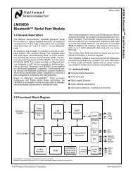
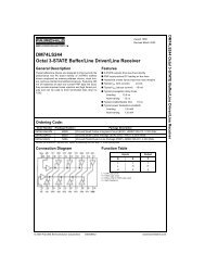
MOWAYTitle: mOway Beginner <strong>Manual</strong>Rev: v3.0.0 – June 2011Page 7 of 473. Robot mOwayThis chapter describes each of the parts that constitute the mOway. It is importantto highlight that it is not necessary to know the total functioning of the robot to be ableto program it, at least not at the level of detail explained here.The following elements are to be found inside mOway:• Processor• Drive system• Sensors and indicators group• Power supply system• An expansion connectorGearIR_RX_RIR_RX_RTEMPMICPIC18f86j50BATTERYMETERPIC16F687EncoderACCELELINE_RX_RLINE_TXLED_BRAKEENGINEFRONT_LEDIR_RX_LLINE_RX_RLINE_TXLINE_RX_LLED_GREENLIGHT_SENLED_REDEXPANSIONH BridgeFREEPADLED_BRAKEIR_RX_LSPEAKEREncoderLINE_RX_RLINE_TXENGINEGearImage 1. Diagram of mOway’s parts3.1. ProcessormOways are governed by a 4 Mhz PIC18F87J50 microcontroller manufactured byMicrochip Technologies. All the peripherals distributed throughout the whole robot areconnected to its input/output ports. Some of them need a digital input or output, othersneed an analog input or output and others, instead, are controlled by one of the I2C/SPIcommunication buses. The table below describes how the microcontroller pins aredistributed.www.moway-robot.com
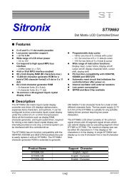
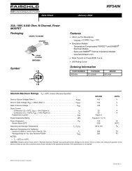
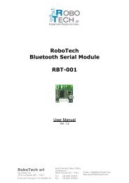
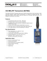
MOWAYTitle: mOway Beginner <strong>Manual</strong>Rev: v3.0.0 – June 2011Page 8 of 473.2. Drive systemTo be able to move the mOway uses a double servo-motor group. It includes bothan electronic part and a mechanical one. The electronic part is mainly in charge ofcontrolling the motor’s speed and the mechanical part allow the mOway to moveunhindered over different terrains with adequate power.Image 2. Drive system: electronic and mechanicalThe servo-motor group includes different features:1. Speed control: controls the speed of each motor.2. Time control: controls the time <strong>for</strong> each command with a 100 ms precision.3. Traveled distance control: Controls the distance traveled by each commandwith a precision of 1 mm aprox.4. General speedometer: counts distances traveled since the initial command.5. Angle control: controls the angle when the mOway rotates.The microcontroller sends the I2C command to the drive system that controls themotors and there<strong>for</strong>e releasing the main microcontroller so it can carry out other tasks.Speed control is carried out by means of proportional control with negativefeedback from the encoders’ signal. The illustration displays the controlling system. Themicrocontroller feeds the motors through an H bridge controlled by pulse widthmodulation (PWM) signals. Wheel rotation is monitored by an encoding sticker and aninfrared sensor. When the sticker shows its black segment, the logical output shall be 1www.moway-robot.com
MOWAYTitle: mOway Beginner <strong>Manual</strong>Rev: v3.0.0 – June 2011Page 9 of 47and when it shows the white sector the output shall be 0. The microcontroller analyzesthese signals (it can determine the exact wheel speed by measuring the pulse width) andacts on the motors. This way, the mOway will be able to keep the speed constant on anysurface.Image 3. Motor controlTo send a movement command to the robot, via the main microcontroller, all weneed to do is send the movement command parameters. To this end some libraries weredesigned in assembly and C language to simplify communications through somefunctions which are responsible <strong>for</strong> I2C communications. The <strong>for</strong>mat <strong>for</strong> these frames isexplained in the motors and drive system library section.The table below describes connections between the main PCB and the servomotorunit.3.3. Sensor and indicators groupThis group consists of different luminous sensors and indicators, connected to themOway microprocessor, through which the robot interacts with the external world:• Two line tracking sensors.• Four obstacle detection sensors.• A light sensor.• An expansion connector.• Four LED diodes.• Temperature sensor.www.moway-robot.com
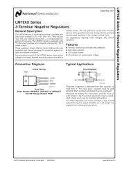
MOWAYTitle: mOway Beginner <strong>Manual</strong>Rev: v3.0.0 – June 2011Page 10 of 47• Speaker.• Microphone.• Accelerometer.• Battery level.Image 4. Sensors and indicators group3.3.1. Line sensorsThe line tracking sensors are two reflection optocouplers mounted on the top frontpart of the robot. They use infrared light reflection to detect the color of the terrain atthe point where the robot is.These two sensors are connected to two microcontroller analog ports so strongterrain contrasts, like white lines on black backgrounds, can be detected. They are alsocapable of distinguishing different tones.The Vishay CNY70 sensor has a compact construction where the emitting lightsource and the detector are arranged in the same direction to be able to detect by usingthe reflective IR beam the light reflected in the terrain.In the images below the three possible cases can be observed:1. Clear surface: A white surface reflects all the infrared light andthere<strong>for</strong>e we obtain a low voltage reading at the transistor’s output whenin regular mode.www.moway-robot.com
MOWAYTitle: mOway Beginner <strong>Manual</strong>Rev: v3.0.0 – June 2011Page 11 of 47Image 5. Line tracking sensor on a clear surface.• Colored surface: A colored surface reflects part of the emitted lightobtaining an intermediate voltage at the microcontroller’s analogchannel input. This way colors are easily identified 1 .Image 6. Line tracking sensor on a colored surface.1. Dark surface: A dark surface reflects very little light obtaining a highvoltage reading at the sensor’s output.Image 7. Line tracking sensor on a dark surface.1 Due to CNY70 tolerance two different sensor can differ.www.moway-robot.com
MOWAYTitle: mOway Beginner <strong>Manual</strong>Rev: v3.0.0 – June 2011Page 12 of 47Image 8. Location of line sensors3.3.2. Obstacle detection sensorsSimilar to line tracking sensors, obstacle detection sensors also use infrared lightto detect objects located in front of the mOway. The sensor includes two infrared lightemittingsource (Kingbright KPA3010-F3C) and four receivers placed on both sides ofmOway.The output of the Sharp PT100F0MP receivers are connected to themicrocontroller’s analog inputs so it can detect the presence of any object (digital mode)and also measure how far away it is (analog mode) 2 .The sensor functions similarly to the line tracking sensor. The light emittergenerates a 70us pulse which allows the receiver to capture any obstacle using afiltering and amplifying stage. Once the signal is processed electronically, the PIC canmeasure it by means of the ADC or as a digital input. The digital distance range is closeto 3cm and a bright environment is recommended to enhance infrared light reflection.Image 9. Obstacle detection sensor2 Due to tolerance two different sensors can differ from each other.www.moway-robot.com
MOWAYTitle: mOway Beginner <strong>Manual</strong>Rev: v3.0.0 – June 2011Page 13 of 473.3.3. Light sensorImage 10. Location of Obstacle SensorThis sensor allows mOway to recognize the light intensity that enters through asmall half moon-shaped opening on the top part of the chassis. Since it is facing <strong>for</strong>wardit enables it to detect where the light source is located and to act accordingly.The output of the AVAGO APDS-9002 sensor is connected to the analog port ofthe microcontroller so that with a simple reading of the ADC we can register the lightintensity level and any change in intensity levels based on the last reading 3 .Image 11. Location of Light Sensor3.3.4. Expansion connectorThis connector allows the mOway to connect with any commercial modules orelectronic circuits the user may choose.As shown in the above table, it is possible to connect commercial SPI devices. Onthe other hand, the RF BZI-RF2GH4 module available in the market is totallycompatible with mOway and with specific libraries. This module enables the mOway tocommunicate with other robots and with a PC via the RFUsb. With this module it ispossible to create complex collaboration applications without having to worry aboutcomplicated wireless communications.3 Top two-color LED has to be switched off to have a valid measure.www.moway-robot.com
MOWAYTitle: mOway Beginner <strong>Manual</strong>Rev: v3.0.0 – June 2011Page 14 of 47Image 12. RF modules into expansion connector.3.3.5. Temperature sensormOway has installed as a temperature measurer an NTC thermistor from Murata,a semiconductor whose electrical variable resistance decreases as temperature increases.The sensor is located in the front part of the robot, very close to obstacle sensor.The thermistor is connected to the analog port of the microcontroller so that with asimple reading of the ADC it is possible to get the temperature value in that momentand notice any change in it since the last reading 4 .3.3.6. SpeakerThe CMT-1102 speaker from CUI INC directly connected to the microcontroller,is capable to play tones from 250 Hz to 65 KHz.3.3.7. MicrophoneThe CMC-5042PF-AC microphone from CUI INC enables the robot to detectsounds from 100 Hz to 20 KHz.The output is directly connect to an analog input of the microcontroller so that it iscapable to detect not only if there is sound or not (digital mode) but also the intensity ofthe sound with a simple reading of the ADC (analog mode).4 Temperature measured by the sensor can be 5ºC higher than external temperature.www.moway-robot.com
MOWAYTitle: mOway Beginner <strong>Manual</strong>Rev: v3.0.0 – June 2011Page 15 of 473.3.8. AccelerometerAn accelerometer is a device that measures acceleration and the gravity induced<strong>for</strong>ces: the movement and rotation. There are many types of accelerometers, most ofthem based on piezoelectric crystals, but their size is too big. Because of that, it wastried to design a small device in the field of microelectronics, which might improve theapplicability. Then, the MEMS (Microelectromechanical Systems) accelerometers werecreated.An easy way to create an accelerometer is measuring changes in a capacitor.Capacitors can work as sensors or as actuators. In the case of mOway, it is a capacitiveaccelerometer, which consists of two capacitors displaced in differential mode whoseelectrical capacity changes as the acceleration varies.By measuring X, Y, Z axes of the MMA7455L accelerometer fromFREESCALE Semiconductor, it is possible to know if mOway is correctly positioned,inverted or tilted.3.3.9. Battery levelThe robot has a LiPo cell battery rechargeable. For proper operation of themicrocontroller, the battery is connected to one of its analog inputs through a splitter.Thus, with a reading of the ADC battery level can be measured.3.3.10. Front LEDThe front LED is a white LED placed on the front side of mOway. The output ofthe OSRAM LW A6SG LED is connected to a digital output of the microcontroller.3.3.11. Top two-color LEDThis double indicator and the light sensor share the same opening on the top partof the robot. They are connected to two microcontroller digital outputs 5 .5 Please note that since they share the same opening as the light sensor it is fundamental to switchthem off when wanting to per<strong>for</strong>m a light intensity reading.www.moway-robot.com
MOWAYTitle: mOway Beginner <strong>Manual</strong>Rev: v3.0.0 – June 2011Page 16 of 47Image 13. Robot with Front LED and red LED switched on3.3.12. Brake LEDThe brake LED is double indicator placed on the back side of mOway. The outputis connected to one digital outputs of the microcontroller.Image 14. Brake LED location. Switch on green LED.3.3.13. Free PadmOway has implemented a free Pad to allow expert users to connect theirelectronics. It is accessible opening the robot and it´s located near brake LED 6 .3.4. Power Supply SystemmOway’s battery is located inside and accessible only by disassembling theproduct. It is a small rechargeable LiPo cell.The battery can be charged via a computer’s USB port through the mOway’sMINI-USB-B port. There is no need to wait <strong>for</strong> the battery to be completely discharged,6 Advanced users onlywww.moway-robot.com
MOWAYTitle: mOway Beginner <strong>Manual</strong>Rev: v3.0.0 – June 2011Page 17 of 47as it can be plugged in any time since these batteries do not have memory effect (alsoknown as lazy battery effect). These batteries are a perfect power source <strong>for</strong> mOwaydue to their small size, lightness and flexibility.Battery duration depends to a great extent on the active sensors and the amount oftime the motors are used. Charging lasts about 2h.Power supply system controls two LED located in the back part of the robot 7 .Green LED indicates that mOway is switched on and red LED indicates that the batteryis charging. When the battery is full red LED will switch off 8 .Image 15. Charging (red) and switched on (green)3.5. RF module and RFUsb 9RF module allows communicate with other mOways or with PC using RFUsb. 10 .7 These LEDs can´t be controlled by the user.8 This LED can swap between on and off when the battery is fully charge because there is energyconsumption when mOway is plugged.9 Available in some packs10 Available in some packswww.moway-robot.com
MOWAYTitle: mOway Beginner <strong>Manual</strong>Rev: v3.0.0 – June 2011Page 18 of 47Image 16. RF moduleRF module is connected in expansion connector and it is very easy to use withmOwayWorld 11 .Image 17. RFUsbThe BZI-RF2GH4 radio-frequency communications module is based on thenRF24L01 transceptor manufactured by “Nordic Semiconductors”. This integratedcircuit has been fitted with all the logic required to establish wireless bidirectionalcommunications with acknowledgement of receipt. Communications with themicrocontroller is made via an SPI bus.The main characteristics of the BZI-RF2GH4 module are as follows:• Low consumption.• Working frequency: 2.4GHz,• Transmitting power between-18 and 0 dBm,• Transmission speed between 1 and 2 Mbps,• 128 in transmission channels selectable by the SPI bus.In addition to the CI nRF24L01, the BZI-RF2GH4 is also fitted with all theassociated electronics <strong>for</strong> its correct operation plus a microstrip antenna on the same11 Option not yet availablewww.moway-robot.com
MOWAYTitle: mOway Beginner <strong>Manual</strong>Rev: v3.0.0 – June 2011Page 19 of 47board with the impedance adaptation network. In this way the user can <strong>for</strong>getcompletely about the hardware required to implement the radio part of his application.As interface, the device has four pins available <strong>for</strong> the SPI bus, two more pins <strong>for</strong>controlling the module and another two <strong>for</strong> the supply.In order to facilitate the handling of the module, a number of libraries have beendeveloped to simplify and shorten the development time of wireless applications withthese modules.www.moway-robot.com
MOWAYTitle: mOway Beginner <strong>Manual</strong>Rev: v3.0.0 – June 2011Page 20 of 473.6. Camera module and mOway VideocapThanks to the camera module (mOway Camera Board 12 ) it is possible to displayon the computer what mOway is “watching” . Camera board sends images wirelessly tothe video mOway Videocap 13 .Image 18. Camera module mOway Camera BoardCamera module is connected in expansion connector and it is very easy to usewith mOwayWorld 14 . Video mOway Videocap must be connected to an USBconnector of the computer.Camera control is per<strong>for</strong>med by Microchip MCP23S08 device, which is aninput/output port managed by SPI. A library is provided to make easier <strong>for</strong> user todevelop programs with the camera module. The basic functions are the camera ON andOFF, and the selection of the transmission channel from de camera to the video mOwayVideocap. User have to select the same channel (from 1 to 4) both in program andmOway Videocap. The status of the camera is shown by a LED on camera board.As interface, the device has four pins available <strong>for</strong> the SPI bus, two more pins <strong>for</strong>controlling the module and another two <strong>for</strong> the supply.NOTE: Both camera transmission and RF module transmission are in the samefrequency band. So that, when camera is active, RF module reception distancedecreases.12 Available in some packs13 Available in some packs14 Option not yet availablewww.moway-robot.com
MOWAYTitle: mOway Beginner <strong>Manual</strong>Rev: v3.0.0 – June 2011Page 21 of 474. First Steps4.1. mOway Pack installationIn mOwayPack (available in the webpage or in the installation CD) you will findthe software, mOway´s libraries, test programs and documentations.Following setup steps you will have all the resources:• Beginner’s and User manual.o Beginner’s manual includes all you need to start working with mOway.o User manual contains detailed description of the robot.• mOwayWorld software.o This software controls all aspects of the robot: program download,battery charge control, radio control 15 , RFUsb 16 management and C orassembler programs download.• Reference projects in assembler, C and mOwayWorld.o Example projects to start working with mOway easily.• RFUsb Drivero Driver <strong>for</strong> RFUsb 17 that allows the communication between robots andPC.• mOway Videocap Drivero Driver <strong>for</strong> mOway Videocap 18 that allows to grab images from mOwaycamera to display on PC.If a security warning message appears during installation, please click on “installdriver anyway”.15 Option not yet available16 Module not available in all kits17 Module not available in all kits18 Module not available in all kitswww.moway-robot.com
MOWAYTitle: mOway Beginner <strong>Manual</strong>Rev: v3.0.0 – June 2011Page 22 of 47Image 19. CD4.2. Download a program to mOwayDownload process is always executed in mOwayWorld. This application candownload to the robot mOwayWorld projects, assembler projects (compiled with Mplabo gputils) and C (C18 compiler) projects.Steps to download a program to mOway:• Connect mOway to the PC through USB. The robot doesn´t need anydriver.• Open mOwayWorld application.• Open or create a project in mOwayWorld, or import 19 a .HEX file fromassembler or C project.• Click download bottom. If a .HEX file has been imported the downloadprogress will start automatically.• Disconnect the robot and check the project.mOwayPack provide 8 compiled projects: 3 to check sensors, 3 to check thedrive system and 2 programs that are explained in the next section.4.3. RFUsb instalation• This is a device that allows to communicate the PC and mOway.A driver that it´s included in mOwayPack is required:• The first time the RFUsb is connected, the PC will detect it as a newdevice and an “Assistant <strong>for</strong> new hardware found” message will bedisplayed. Select the No, not this time option.19 Option not yet availablewww.moway-robot.com
MOWAYTitle: mOway Beginner <strong>Manual</strong>Rev: v3.0.0 – June 2011Page 23 of 47• In the following window select the recommended option: Install softwareautomatically.Image 20. Driver installation Wizard• Now the installation process will begin.Image 21. Windows XP driver installation• Assistant will then indicate that the hardware is installed.www.moway-robot.com
MOWAYTitle: mOway Beginner <strong>Manual</strong>Rev: v3.0.0 – June 2011Page 24 of 47Image 22. Driver installed in Windows XP• Check if mOway’s software has detected the RFUsb.4.5 mOway Videocap drivers installationAs with RFUsb device, a driver that it´s included in mOwayPack is requiredto use video capturer:• The first time the mOway Videocap is connected, the PC will detect it asa new device. Driver installation runs automatically. If it doesn´t, an“Assistant <strong>for</strong> new hardware found” message will be displayed. Selectthe No, not this time option.• In the following window select the recommended option: Install softwareautomatically.• Now the installation process will begin.• Assistant will then indicate that the hardware is installed.• Check if mOway’s software has detected the mOway Videocap.www.moway-robot.com
MOWAYTitle: mOway Beginner <strong>Manual</strong>Rev: v3.0.0 – June 2011Page 26 of 475.2. mOwayWorld workspaceThe following lines describe the different parts of mOwayWorld workspace.5.2.1. ToolbarToolbar allows the user to manage the project, edit the flowchart, create variables,program mOway robot and many other functions.Image 24. Toolbar5.2.2. Flowchart EditorThe Flowchart Editor window is where modules are placed and connected todevelop the program. When a new project is created, this window is empty except <strong>for</strong>the starting point. In flow diagrams there is always a “starting point” from which theprogram begins.Image 25. Flowchart Editor windowwww.moway-robot.com
En general, del total de los municipios de México que cuentan con in<strong>for</strong>mación sobreel registro de los nacimientos, la mayoría presentan un grado eficiente de registrooportuno, dentro del periodo analizado. De acuerdo con la in<strong>for</strong>mación obtenida parael año 2009, tres de cada cuatro municipios en el país, presentan grados de cobertura“Alto” y “Muy alto”, lo que representa 87% de los nacimientos registrados en 2009.Cuadro 1. Estados Unidos Mexicanos: registro oportuno de nacimientos de menoresde 1 año por tipo de municipio de registro según grado de coberturaTotal de municipiosPoblaciónPoblaciónNacimientosPorcentaje deregistro oportunoPorcentaje de coberturaA partir de censosRegistrados de 0 a 11 meses1999 2009 2000 2010 1999 2009 1999 2009 1999 2009Nota: Para Oaxaca, se utilizó municipio de residencia habitual de la madre.Para 2000, se excluyen 10 municipios en su mayoría de reciente creación, los cuales no cuentancon in<strong>for</strong>mación de registro sobre nacimientos.En estos municipios se concentra una población de 65,831 habitantes.Fuente: INEGI. Estadísticas Vitales. Bases de Datos 1999, 2009.Censo de Población y Vivienda, 2010.XII Censo General de Población y Vivienda, 2000.Sin embargo, a pesar de los altos grados de cobertura oportuna que presentan lamayoría de los municipios de México, existen todavía 31 municipios (22 rurales, 3urbanos y 6 mixtos) que registran un grado de cobertura “muy bajo”, es decir, quemenos del 25% de los nacimientos ocurridos en un año se registran oportunamente(2 de cada 10 niños o niñas).26
MOWAYTitle: mOway Beginner <strong>Manual</strong>Rev: v3.0.0 – June 2011Page 28 of 475.2.4. ArrowsModules execution order is established by means of arrows. In order to connectthe modules, following steps must be taken:• Place the cursor over a module until red and white marks appear.• Click on one of these marks.• Click on one of the next module mark.Image 27. Arrow drawingIn order to describe a loop, the procedure is similar but in this case the arrowstarts on a module mark and finishes on another mark of the same block.Image 28. Arrow drawing <strong>for</strong> a loopIf more precision is needed, the connector tool is very useful. To activate it, clickon “Connect tool” icon in the toolbar.www.moway-robot.com
MOWAYTitle: mOway Beginner <strong>Manual</strong>Rev: v3.0.0 – June 2011Page 29 of 475.3. First program in mOwayWorldIn order to develop your first program, first you must create a project (seeprevious chapter). This first basic program will make mOway avoid obstacles.1. Once a new project is created, the program starts with a 2-second delay. Just adda “Pause” module and configure it with a constant value of 2.2. The command to make green LED blink is added with the “Lights” module.Configuration of both modules are shown below.Image 29. Pause and LED configuration3. The end of the program is added (“Finish” module) so that the application canbe compiled.4. The program is compiled and recorded into the robot clicking on “ProgrammOway” button in the toolbox, shown in the next image.5. Test the program and check that after waiting 2 second the green LED lights up.www.moway-robot.com
MOWAYTitle: mOway Beginner <strong>Manual</strong>Rev: v3.0.0 – June 2011Page 30 of 47Image 30. Flowchart of the program and “Program mOway” button6. In order to detect obstacles, four “Sensor Check Obstacle” has to be added andconfigured one <strong>for</strong> each obstacle sensor.Image 31. Check Obstacles configurationwww.moway-robot.com
MOWAYTitle: mOway Beginner <strong>Manual</strong>Rev: v3.0.0 – June 2011Page 31 of 477. Condition modules have a true output and false output. If the condition is true(obstacle detected) the corresponding LED lights up, otherwise it remains off.8. Test the program and check that the front LEDs light up when an obstacle isdetected.Image 32. First mOwayWorld program: obstacle detection9. We add movement to the robot: straight on indefinitely until an obstacle isfound.10. When an obstacle is found, a command is sent to the robot to rotate 180º. Therobot will continue to move in a straight line when the rotation is completed.www.moway-robot.com
MOWAYTitle: mOway Beginner <strong>Manual</strong>Rev: v3.0.0 – June 2011Page 32 of 47Image 33. Movement and Rotation configurationImage 34. End of first program in mOwayWorldwww.moway-robot.com
MOWAYTitle: mOway Beginner <strong>Manual</strong>Rev: v3.0.0 – June 2011Page 33 of 475.4. ModulesThe mOway programming consist of functions or actions that control the robot.Modules are these functions or actions that mOway can carry out: moving, readingsensors, transmission of radiofrequency messages, etc. These modules are groupeddepending on their function.For more flexible programs some modules allows to use variables <strong>for</strong> some oftheir values (<strong>for</strong> example, speed value, pause time, read sensor values, etc.). A variablecontains a value that can change during the execution of the program. These variablescan be created from some modules. They can also be defined from the toolbar, byclicking on “Variables” and then clicking on “New variable”. A name and an initialvalue have to be selected.Image 35. A new variable creation.Each of the modules included in mOwayWorld are described below.www.moway-robot.com
MOWAYTitle: mOway Beginner <strong>Manual</strong>Rev: v3.0.0 – June 2011Page 34 of 475.4.1. <strong>Moway</strong> ActionsThis group of modules allows to control mOway’s actuators: engines, speaker andLEDs. Functions of these modules can be per<strong>for</strong>med <strong>for</strong> a user-defined period of time ordistance if the “finish time/distance limit be<strong>for</strong>e continuing with the next action inflowchart” option are selected. If this option is not selected, the function will beexecuted indefinitely until another module changes the current function.• Movement – StraightmOway robot has two motors, one in each wheel. These give it agreat flexibility in its movements. Movement straight command makesmOway to go <strong>for</strong>ward or backward describing a straight line trajectory.Speed value can be modified.Image 36. Movement – Straight configuration window• Movement – FreeFree movement is similar to straight movement, but in this case thespeed of each motor can be adjusted separately.www.moway-robot.com
MOWAYTitle: mOway Beginner <strong>Manual</strong>Rev: v3.0.0 – June 2011Page 35 of 47Image 37. Movement – Free configuration window• Movement – TurnIn this function, drive system will calculate the speed of the motors inorder to be able to trace a curve, indicating the speed and turning radius.Image 38. Movement – Turn configuration windowwww.moway-robot.com
MOWAYTitle: mOway Beginner <strong>Manual</strong>Rev: v3.0.0 – June 2011Page 36 of 47• Movement – RotateWith this command, mOway will rotate either on its centre or onone of its two wheels. Turning direction and rotation speed can be defined.Image 39. Movement – Rotate configuration window• Movement – StopThis command stops mOway’s engines.• Sound – PlayThis function allows mOway to emit tones from 250 Hz to 65 KHz.It is possible to define the time that the speaker will be activated.www.moway-robot.com
MOWAYTitle: mOway Beginner <strong>Manual</strong>Rev: v3.0.0 – June 2011Page 37 of 47Image 40. Sound – Play configuration window• Sound – StopStops the speaker sound.• LightsThis module allows to operate on mOway's LED diodes. You canturn them on, turn them off or make them blink.Image 41. Lights configuration windowwww.moway-robot.com
MOWAYTitle: mOway Beginner <strong>Manual</strong>Rev: v3.0.0 – June 2011Page 38 of 475.4.2. Sensors CheckThis group of modules allows to get the mOway’s sensors values. These areconditional modules, so that they have two different outputs: if the condition configuredin the module is true, the output will be “true” (green mark in the flowchart). Otherwise,if the condition is false, the output will be “false” (red cross in the flowchart).• ObstacleThis module checks the digital value of the four obstacle sensors. Each sensor canper<strong>for</strong>m one of the following conditions:o obstacle detectedo no obstacle detectedo detection inactiveIn addition, it allows to check the AND or OR boolean operation. If AND optionis checked, all the conditions must be true to get a “true” output. On the other hand, ifOR is checked, just one of all the condition has to be true to get a “true” output.Image 42. Sensors Check - Obstacles configuration windowwww.moway-robot.com
MOWAYTitle: mOway Beginner <strong>Manual</strong>Rev: v3.0.0 – June 2011Page 39 of 47• LineThis module checks the digital value of line sensors. This module is very useful<strong>for</strong> making mOway follow a line (black or white) on the floor, detect boundaries, etc.Each sensor can per<strong>for</strong>m one of the following conditions:o black line detectiono white line detectiono detection inactiveIn addition, it allows to check the AND or OR boolean operation. If AND optionis checked, all the conditions must be true to get a “true” output. On the other hand, ifOR is checked, just one of all the condition has to be true to get a “true” output.Image 43. Sensors Check – Line configuration window• NoiseThis module has a “true” output if mOway detects a loud sound. Ithas not any configuration window.• TapThis module has a “true” output if mOway detects a tap or a highacceleration. It has not any configuration window.www.moway-robot.com
MOWAYTitle: mOway Beginner <strong>Manual</strong>Rev: v3.0.0 – June 2011Page 40 of 475.4.3. DataThis group of modules make it possible to read, write and modify data thatmOway robot can provide from sensors and internal memory.Data is stored in user-defined variables. A variable is created by clicking on“Variable” on the toolbar and then clicking on “New variable”. A name and an initialvalue have to be defined <strong>for</strong> this new variable (see previous chapter).Some of the modules allow to create these variables directly from theirconfiguration window. This permits to configure the module with values that can bemodified during the execution of the program.NOTE: Each variable is stored in one byte of mOway’s internal memory, whichmeans that the value of the variable goes from 0 to 255.• CalculateThis module adds (+=) or subtract (-=) two values. First parameteris always a variable and it stores the operation result. Second parametercan be a constant or a variable.• Reset mOway DataThis module initializes time and distance counters stored inmOway’s internal memory.• Assign VariableThis group of modules allows to assign a value to a user-defined variable. Thisvalue can be constant or the analog value of mOway’s sensors.o Value: assigns a constant value to a variable.o Time: assigns elapsed time to a variable. Value goes from 0to 255 tenths of a second.o Speed: assigns the speed value of one of the wheels to avariable. Value goes from 0 (stopped) to 255 (maximumspeed).www.moway-robot.com
MOWAYTitle: mOway Beginner <strong>Manual</strong>Rev: v3.0.0 – June 2011Page 41 of 47o Distance: assigns distance value covered by mOway to avariable. Value goes from 0 to 255 centimetres.o Angle: assigns the value of mOway turning angle to avariable. Value goes from 0 (0 degrees) to 100 (correspondingto 360 degrees).o Brightness: assigns the light sensor value to a variable. Valuegoes from 0 (dark) to 100 (light).o Line: assigns one of the line sensors value to a variable.Value goes from 0 (white colour detection) to 255 (blackcolour detection).o Obstacle: assigns one of the obstacle sensors value to avariable. Value goes from 0 (no detection) to 100 (closestdetection).o Accelerometer: assigns one of accelerometer axis value to avariable. Value goes from 0 (negative acceleration limit) to255 (positive acceleration limit). When there is notacceleration, the value is 127 (range mid-point).o Noise: assigns microphone value to a variable. Value goesfrom 0 (silence) to 255 (loud noise).o Temperature: assigns the robot temperature value to avariable. Value goes from 0ºC to 255ºC.o Battery: assigns battery level to a variable. Value goes from0% to 100%.• CompareThis group of modules allows to compare a variable or a sensor value withanother value (constant value or user-variable). The following are the comparisonoperators: equal (==), different (), greater (>), greater or equal (>=), less (
MOWAYTitle: mOway Beginner <strong>Manual</strong>Rev: v3.0.0 – June 2011Page 42 of 47o Speed: compares one of the wheels speed value. Valuesgoes from (stopped) to 100 (maximum speed).o Distance: assigns distance value covered by mOway to avariable. Value goes from 0 to 255 centimetres.o Angle: compares the value of mOway turning angle. Valuegoes from 0 (0 degrees) to 100 (corresponding to 360degrees).o Brightness: compares the light sensor value. Value goesfrom 0 (dark) to 100 (light).o Line: assigns one of the line sensors value to a variable.Value goes from 0 (white colour detection) to 100 (blackcolour detection).o Obstacle: compares one of the obstacle sensors value to avariable. Value goes from 0 (no detection) to 100 (closestdetection).o Accelerometer: compares one of accelerometer axis value.Value goes from -2g (negative acceleration limit) to 2g(positive acceleration limit). When there is not acceleration,the value is 0 (NOTE: g value is 9.81m/s 2 ).o Noise: compares microphone value. Value goes from 0(silence) to 100 (loud noise).o Temperature: compares the robot temperature value. Valuegoes from 0ºC to 255ºC.o Battery: compares battery level. Value goes from 0% to100%.www.moway-robot.com
MOWAYTitle: mOway Beginner <strong>Manual</strong>Rev: v3.0.0 – June 2011Page 43 of 475.4.4. Flowchart Control• PauseThis module allows to insert a pause in the program with a durationset in multiples of 0.05 seconds. The pause parameter may be a constant ora variable.• FinishThis module sets the program end. If the program consist of an infiniteloop, this module is not necessary.5.4.5. ExpansionThis group of functions allows to control the expansion connector of mOwayrobot, either to use radiofrequency (RF) communication, or user expansion modules.WARNING!Only advanced users can use the pinout configuration. Any incorrect connectionof electronic elements to the expansion connector may damage the robot irreversibly.• Module IO – ConfigureThis module configures the expansion connector pins as inputs oroutputs and assigns a initial value <strong>for</strong> outputs.Image 44. Module IO – Configuration configuration windowwww.moway-robot.com
MOWAYTitle: mOway Beginner <strong>Manual</strong>Rev: v3.0.0 – June 2011Page 45 of 47Image 46. Communicate – Start configuration window• Communicate – StopThis module stops the RF communication. It has not anyconfiguration window.• Communicate – SendThis module makes it possible to transmit a frame to a specificaddress. The address of the receptor and the data, which can consists ofconstants or variables, must be indicated in the frame. If the sent data hasbeen received by the receptor, the output is “true”. Otherwise the output is“false”.Be<strong>for</strong>e using this conditional, the RF communication must be configured usingthe "Communicate - Start" module. All the robots taking part in the RF communicationmust have the same channel and different addresses.Image 47. Communicate – Send configuration windowwww.moway-robot.com
MOWAYTitle: mOway Beginner <strong>Manual</strong>Rev: v3.0.0 – June 2011Page 46 of 47• Communicate – ReceiveThis module makes it possible to receive a frame from a specificaddress. It must be indicated at least two variables: one <strong>for</strong> collecting thetransmitter address and the other <strong>for</strong> the data. If the data sent by thetransmitter has been received correctly, the output is “true”. Otherwise theoutput is “false”.Be<strong>for</strong>e using this conditional, the RF communication must be configured usingthe "Communicate - Start" module. All the robots taking part in the RF communicationmust have the same channel and different addresses.Image 48. Communicate – Receive configuration windowwww.moway-robot.com
MOWAYTitle: mOway Beginner <strong>Manual</strong>Rev: v3.0.0 – June 2011Page 47 of 47www.moway-robot.com